

Page 1
Read and understand all instructions and warnings before operating or using this product.
This product is only intended and only safe for transporting ladders. It is the responsibility of the user to secure these
materials to the rack before transporting.
Ladders must be secured per ANSI standard A142.2-1990 paragraph 8.4.4. Ladder damage will occur from road shock
and vehicle vibration if the ladder is not properly secured to the ladder rack. Bouncing and side to side motion of an
improperly secured ladder will cause wear and weaken the ladder. Using a damaged ladder could lead to structural collapse resulting in serious injury or death. Place ladder in a raised position before transporting. Driving with rack in lowered
position may cause serious injury or damage to vehicle, ladder, rack or persons.
Any modification or unintended use of this product shall immediately void all manufacturers warranties. Manufacturer disclaims all liability for injuries to persons or property resulting from any modification to, or unintended use of this product.
Never load your rack to exceed the safe capacity of your vehicle. Heavy loads when carried high can dangerously alter the
center of gravity.
Loads should be approximately centered front to rear. Failure to do this will cause damage to the vehicle roof. Long loads
that extend out the rear of the vehicle will prevent the rear hatch from fully opening and cause damage if attempted.
WARNING
–ATTENTION–
–NOTICE–
CAUTION
ASSEMBLY INSTRUCTIONS
MODEL 254 EZ-GLIDE™SYSTEM
DRIVER SIDE CLAMP KIT
TOOLS REQUIRED
• 1/2" Open or Box End Wrench
• 3/8" Drive Socket (1/2")
• 3/8" Drive Ratchet
• 3/32" Allen Wrench
PARTS LIST
See Page 2
• Front Rail
• Rear Rail
• Rail Connector
• Pivot Tube Bracket
• Front Ladder Stop
• Handle
• Rear Ladder Clamp
• Handle Pivot Tube
1 Clamp Down Kit
4 5/16-18 x 1" Hex Hd. Bolt
13 5/16-18 Nylon Lock Nut
20 5/16" Flat W
asher
2 5/16-18 x 2" Hex Hd. Bolt
4 5/16-18 x 2-3/4" Hex Hd. Bolt
2 Bushing (see page 2)
1 Cotter Pin
2 5/16-18 x 2-1/2" Carriage Bolt
1 5/16-18 x 2-1/2" Hex Hd. Bolt
1 Handle Pivot Ball W/Allen Screw
(see page 2)
HARDWARE KIT
See Page 3
Check these kits to be sure the following parts are included.
Approximate assembly and Installation time:
30 min. per unit (1/2 hr.) depending on van equipment and installer experience.
IMPORTANT BEFORE YOU BEGIN
Read these instructions and warnings completely before installation.
1
Part No. 24-0109 REV. D ECN 5315 0505/13
Page 2
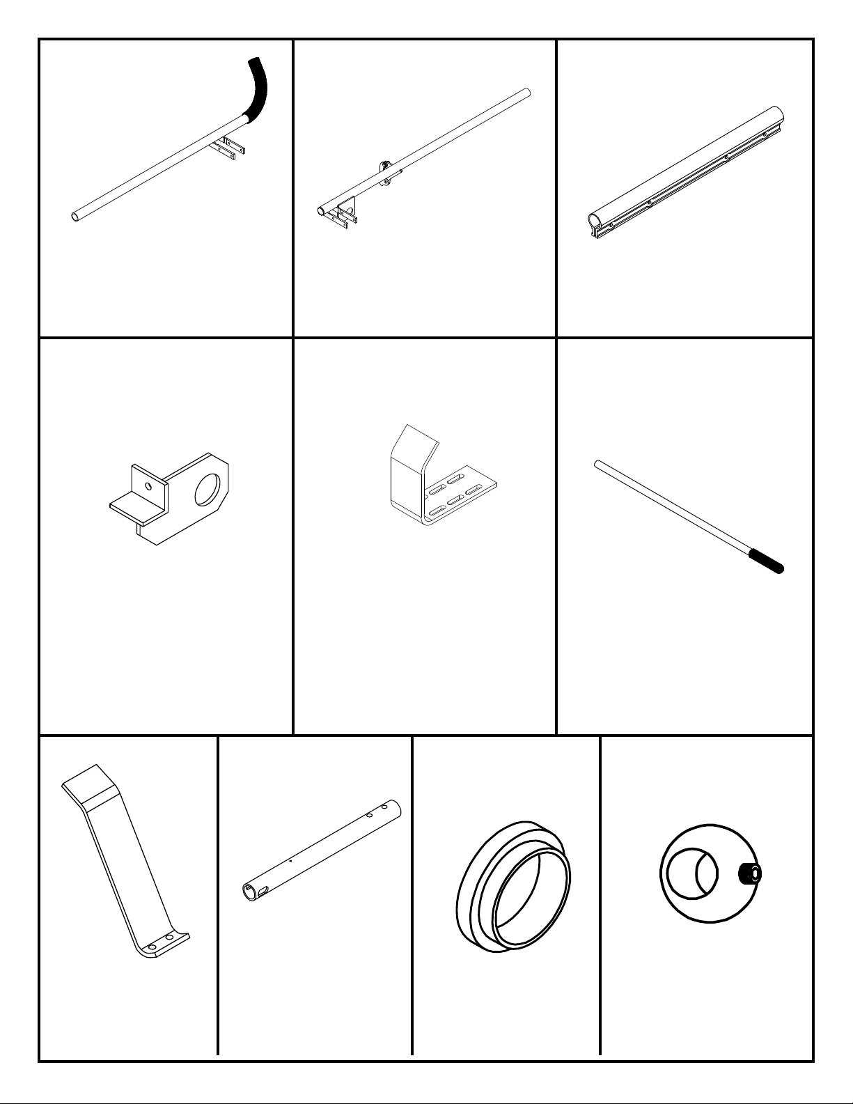
Front Rail
2
Qty. 1
Rear Rail
Qty. 1
Rail Connector
Qty. 1
Pivot Tube Bracket
Qty. 1
Rear Ladder Clamp
Qty. 1
Front Ladder Stop
Qty. 1
Handle Pivot Tube
Qty. 1
Plastic Bushing
Qty. 1
Handle
Qty. 1
Handle Pivot Ball
W/ Allen Screw
Qty. 1
Page 3
3
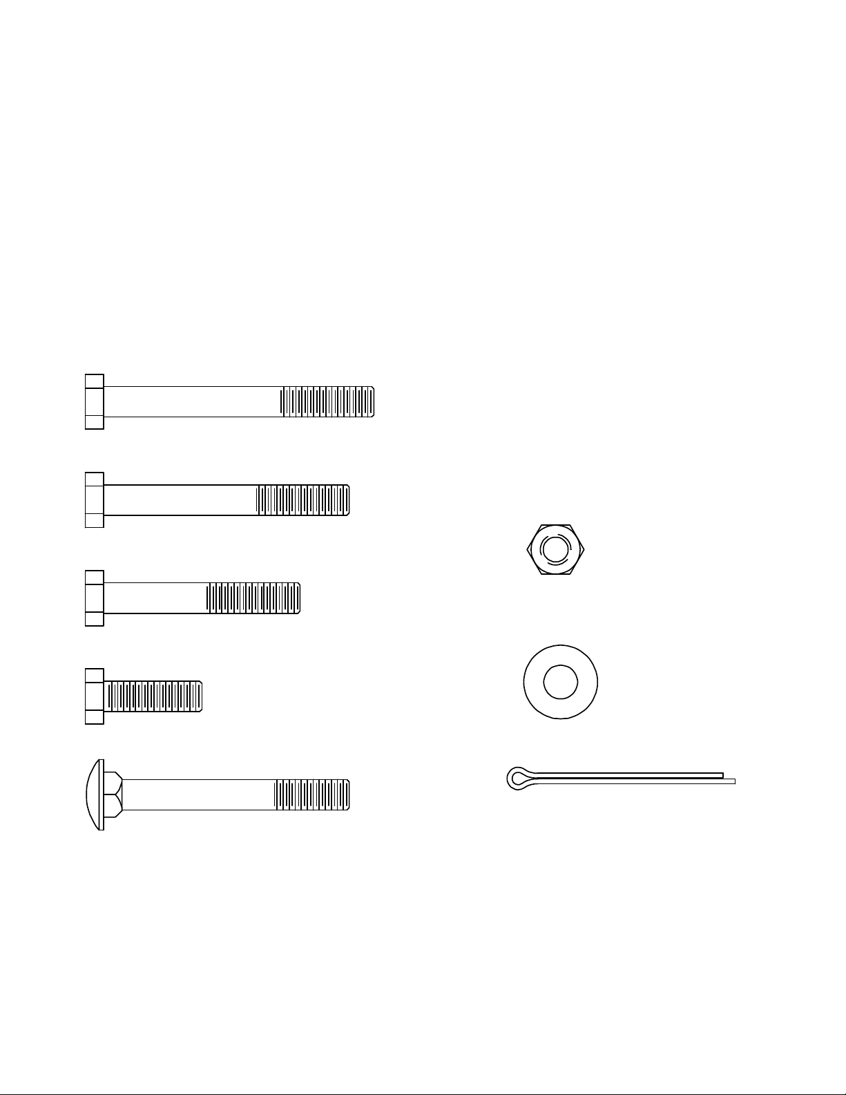
4 5/16 18 x 2 3/4 Hex Hd. Bolt
2 Bushing (See Page 2)
1 Cotter Pin
2 5/16-18 x 2-1/2" Carriage Bolt
1 5/16-18 x 2-1/2" Hex Hd. Bolt
1 Handle Pivot Ball W/ Allen Screw
(See Page 2)
5/16-18 x 2-3/4" Hex Hd. Bolt
5/16-18 x 2-1/2" Hex Hd. Bolt
5/16-18 x 2" Hex Hd. Bolt
5/16-18 x 1" Hex Hd. Bolt
5/16-18 x 2-1/2" Carriage Bolt
Cotter Pin
5/16-18 Nylon Lock Nut
5/16" Flat Washer
FASTENER CHART
Page 4

STEP 1
4
Install Cotter Pin (A) into Handle Pivot Tube (B)
and slide on Plastic Bushing (C)
REAR CLAMP ASSEMBLY
(C)
STEP 2
Insert Handle Pivot Tube (A)
into Pivot Bracket (B) at the
rear of the rail, until the
bushing is fully seated.
(A)
(B)
(A)
(B)
Page 5

STEP 3
Insert the Handle (A) into the Handle Pivot Tube (B) through the Handle Pivot Ball W/Allen Screw (C). Turn the allen screw
into the ball, making sure it extends into the clearance hole in the handle.
(B)
(A)
STEP 4
Attach Rear Ladder Clamp (A) to the Handle
Pivot Tube (B) as shown with 5/16-18 x 2"
Fasteners
(2) 5/16-18 Nylon
Lock Nut
(B)
(C)
(A)
(4) 5/16 Flat
Washer
(2) 5/16-18 x 2"
Hex Hd. Bolt
STEP 5
Remove "Drivers Side End Stop" from the cross-members
previously installed when the Passenger Side ladder rack
(251, 252, 253) was mounted to the vehicle. If you have
installed an accessory cross-member, one "Drivers Side End
Stop" will remain on one of the cross-members depending on
your application of the Model 254.
Next insert a Plastic Bushing (A) into the Pivot Tube Bracket
(B) and slide it onto the end of the Handle Pivot Tube (C).
Attach Rear Rail (D) to the Rear Cross-Member (E) with
5/16-18 x 2-3/4" Fasteners and the bracket to the
cross-member with a 5/16-18 x 2-1/2" Fastener.
(6) 5/16 Flat
Washer
NOTE: The vehicle mounting is not
shown for clarity.
5/16-18 x 2-1/2"
Hex Hd. Bolt
(D)
(E)
5
(2) 5/16-18 x 2-3/4"
Hex Hd. Bolt
(3) 5/16-18 Nylon
(C)
(A)
Lock Nut
(B)
Page 6

STEP 6
Slide the Rail Connector (A) over the end of the Rear Rail
(B) as shown. Install a 5/16-18 x 1" Fastener.
(Do not tighten at this time.)
(B)
5/16-18 x 1"
Hex Hd. Bolt
(A)
5/16" Flat
Washer
FRONT LADDER STOP ASSEMBLY
STEP 7
Insert the end of the Front Rail (A) into the Connector (B) and install the remaining three 5/16-18 x 1" Fasteners.(Do not
tighten at this time.) Adjust the overall length of (A), (B), and (C) to match the current distance between the cross-mem-
bers of the previously mounted passenger side ladder rack and/or accessory crossmember kit. Place the Connector (B)
over equal distances of the Front Rail (A) and the Rear Rail (C) and then tighten the four fasteners. (When mounting to
cross-members with a distance less then 7 feet apart, the Front Rail (A) and the Rear Rail (C) will have to be
equally cut down. Remove 6" from the Front Rail (A) and 6" from the Rear Rail (C) for a 6 foot distance and 12"
from the Front Rail (A) and 12" from the Rear Rail (C) for a 5 foot distance.) Attach the assembly (A), (B), and (C) to
the front cross-member with 5/16-18 x 2-3/4" Fasteners.
5/16-18 Nylon
Lock Nut
Attach the Front Ladder Stop (D) to the Front Cross-Member (E)
with 5/16-18 x 2-1/2" Fasteners. Adjust the Ladder Stop position
to the location that best fits the ladder being carried.
(3) 5/16-18 x 1"
Hex Hd. Bolt
(C)
NOTE: The vehicle mounting
is not shown for clarity.
(B)
(7) 5/16" Flat
Washer
(A)
6
(5) 5/16-18
Nylon Lock Nut
(2) 5/16-18 x 2-1/2"
Carriage Bolt
(D)
(E)
(2) 5/16-18 x 2-3/4"
Hex Hd. Bolt
Page 7

FINAL ASSEMBLY
7
Page 8

This Warranty is in lieu of all Warranties express or implied. The terms of this Warranty shall not be modified by any party, their successors or assigns. This Warranty
gives you specific legal rights, and you may also have other rights which vary from state to state.
2
3
REPLACEMENT PARTS
ID# PART NUMBER DESCRIPTION USE WITH QUANTITY
1 7362 Handle Assembly Kit (with hardware) 254 1
2 7367 Rear Ladder Clamp (with hardware) 254 1
3 7368 Front Ladder Stop (with hardware) 254 1
4 7369 Rail Connector (with hardware) 254 1
1
4
Handle Pivot Tube
Plastic Bushing
Handle Pivot Ball
(with allen screw)
Handle
Cotter Pin
This LIMITED WARRANTY is made by Knaack LLC, 420 E. Terra Cotta Ave., Crystal Lake, Illinois to the original retail purchaser of KNAACK® or WEATHER
GUARD® products.
KNAACK LLC WARRANTS THAT KNAACK OR WEATHER GUARD PRODUCTS WILL BE FREE FROM DEFECTS IN MATERIAL AND WORKMANSHIP FOR A
PERIOD OF TWO (2)
If, before the
Knaack
replace any defective part. All Warranty repairs shall be made by an authorized KNAACK Product dealer or Knaack LLC approved service company.
to make arrangements
LLC
YEARS FROM DATE OF PURCHASE BY THE ORIGINAL RETAIL PURCHASER.
expiration of the Warranty period, purchaser discovers that the KNAACK or WEATHER GUARD product fails to fulfill the Warranty, purchaser shall contact
for an inspection of the product. If Knaack
LIMITED WARRANTY
LLC
ines a defect exists, Knaack
determ
shall, at its option and expense, repair or
LLC
This Warranty shall not apply if the KNAACK or WEATHER GUARD product has been subjected to misuse, abnormal service or handling, impr
alterations
THE WARRANTY PRINTED ABOVE IS THE ONLY WARRANTY APPLICABLE TO THIS PURCHASE. ALL OTHER WARRANTIES, EXPRESS OR IMPLIED,
INCLUDING BUT NOT LIMITED TO THE IMPLIED WARRANTIES OF MERCHANT ABILITY AND FITNESS FOR A PARTICULAR PURPOSE ARE HEREBY
DISCLAIMED. KNAACK LLC SHALL NOT BE LIABLE FOR ANY INCIDENTAL OR CONSEQUENTIAL DAMAGES ARISING OUT OF ANY BREACH OF THIS
WARRANTY. NOR SHALL THE DAMAGES EXCEED THE RETURN AMOUNT OF THE PURCHASE PRICE PAID BY THE ORIGINAL PURCHASER.
Product fits based on vehicle design available at the revision date. Vehicle manufacturers may change s pecs after the
vehicle produced with a model year date after the revision date, please contact your distributor or Knaack LLC to verify fitting of product to vehicle.
If you have any questions, please call our customer service department at 1-800-456-7865. WEATHER GUARD Products are protected by one or
more
1235100 and; U.K. 2233036. Other patents pending.
made by anyone
of the following patents: U.S. 5145087, 5308126, 4509787, 4573731, 4618083, D-346355, D-346994, D-353574; Canada 1218968, 1224230,
other than a KNAACK or WEATHER GUARD Product dealer or a K
0 E. Terra Cotta
42
Ave, Crystal Lake, IL
KNAACK LLC
60014, 815-459-6020, info@knaack.com
©2002 Knaack LLC
8
naack
LLC
approved s
ervice company.
Part No. 24-0109 REV. D ECN 5315 05/13
oper maintenance, or
revision date, so if you have a
 Loading...