

Page 1
INSTALLATION MANUAL
Universal Roof Mounting Kit
Model 2510F
ATTENTION: PLEASE READ AND UNDERSTAND ALL INSTRUCTIONS AND WARNINGS
BEFORE ASSEMBLING, INSTALLING OR USING THIS PRODUCT.
PLAN YOUR VAN (TIPS FOR FASTER INSTALLATION)
Before drilling for the blind fasteners, check for electrical wiring and air-bag system components.
Use vehicle manufacturer’s provided mounting features when available.
Follow vehicle manufacturer’s guidelines on roof loading and do not overload the roof of your vehicle.
TOOLS REQUIRED PARTS LIST
13mm socket and
driver
13mm wrench Utility Knife
Tape Measure Marker
Drill and 5/16” bit
Flat-Blade
Screwdriver
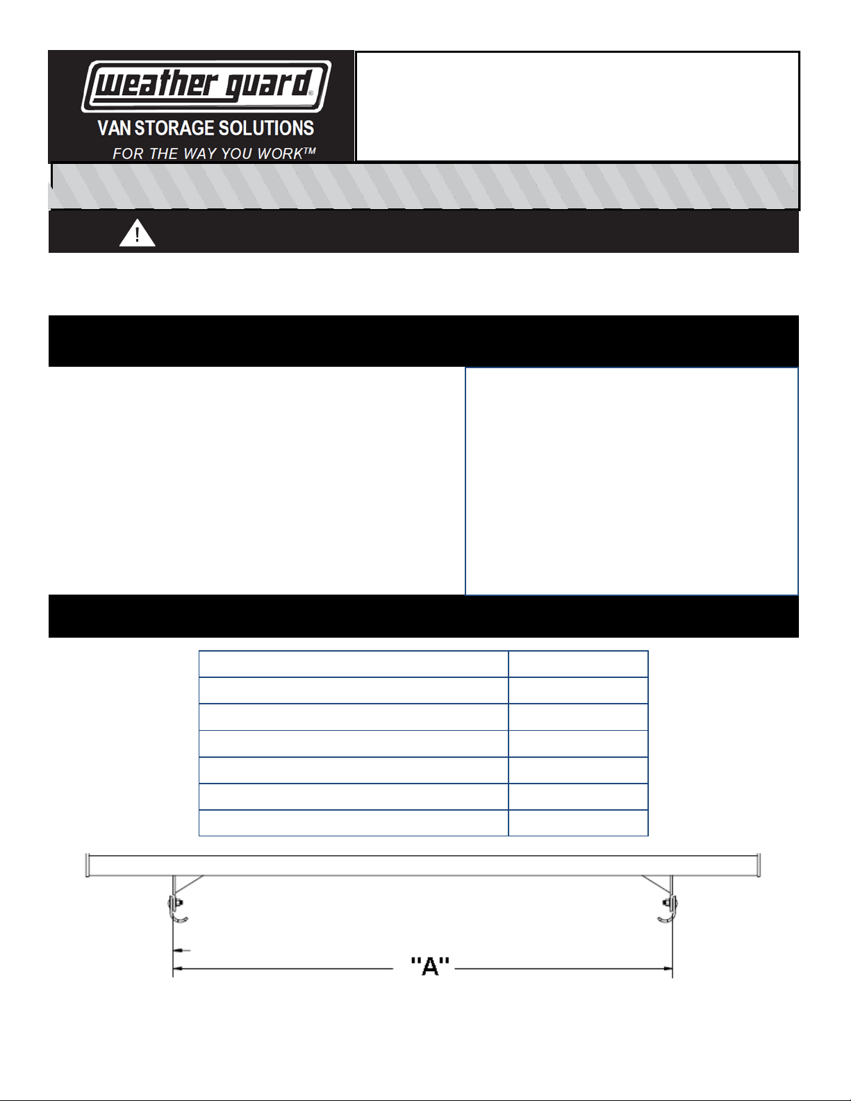
SPACING GUIDELINES
VEHICLE “A” Spacing
Ford Transit Low-, Mid-, High-Roof 55-7/16 in
Ford Transit Connect 2014—front 46-1/8 in
Ford Transit Connect 2014—rear 47-1/8 in
Nissan NV200 45-5/16 in
Mounting Foot (2)
Mounting Foot leveling plate (2)
Mounting foot bolt plate (2)
Curved mounting bracket (2)
M8 x 40mm Stainless steel mounting bolt (4)
M8 x 20 mm Stainless steel cap bolts (4)
M8 Stainless steel flat washers (4)
M8 Stainless steel lock nut (4)
Chevy City Express 45-5/16 in
Nissan NV Low Roof and High Roof 56-1/4 in
“A” spacing is to the outside edges of the mounng feet before aaching the curved mounng plates.
In most applicaons the curved plates will face in to the center of the vehicle, but in some applicaons they will need to face
out. Vehicle dimensions are subject to change and may dier on your specic vehicle, verify t before fully ghtening fas teners.
© 2014 Werner Co. Part No. 24-0329 REV. A ECN 5469 07/14
Page 2
INSTALLATION INSTRUCTIONS
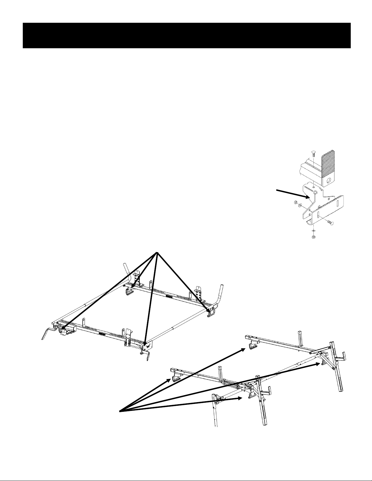
1. Discard the mounting feet included with the ladder rack and replace with the feet from the 2510F
mounting kit. The M8 stainless steel mounting bolts are included for installation to a Ford Transit van.
2. Using the spacing guideline table, place the two mounting feet the distance apart using the spacing in
the table as measured from the outside of each mounting foot.
3. For Model 218-3, Model 223-3-01, or Model 224-3-01 roof racks, loosely bolt the mounting feet to the
cross-member as described in the instruction manual that came with the rack.
4. For 280 and 285 racks, mark the location of the obrounds on the cross-member and drill holes through
cross-member.
5. On some vans, such as the Nissan NV, it may be necessary to mount the curved bracket facing outward to better align to roof-top mounting holes.
Replace the four mounting feet included in the Model 218-3 ladder rack or the
Model 222-3 accessory cross-member with the mounting feet in the Model 2510F
Mounting kit. There are two mounting feet in each Model 2510F mounting kit.
Replace the four mounting feet supplied with the Model 223-3-01 or Model 224-3-01 ladder
racks or the Model 225-3 accessory cross-member with the mounting feet in the Model 2510F
Mounting kit. There are two mounting feet in each Model 2510F mounting kit.
Replace the four mounting feet included in the Model 280-3-01
or Model 285-3-01 ladder racks with the mounting feet in the
Model 2510F Mounting kit. There are two mounting feet in each
Model 2510F mounting kit.
© 2014 Werner Co. Part No. 24-0329 REV. A ECN 5469 07/14
Page 3

WARNING
This product is only intended and safe for use in storing and transporting small tools, equipment and other similar materials. These instructions
are to be followed using the parts and fasteners supplied for proper installation. Any modifications or improper installation of this product will create a
hazardous condition that could result in death, serious personal injury and/or property damage.
All floor mounting bolts near the fuel tank area should be installed from the underside of the vehicle, to guard against the fuel tank
being punctured in the event of a collision. This would mean not using Blind Fasteners in this area. Holes in this area should be
5/16". Ensure ample space in roof ribs and sidewall ribs for mounting screws so as not to puncture exterior roof or wall.
Do not install this product where it could interfere with deployment of air bags. Failure to comply could result in death or serious body injury.
- NOTICE -
Any modification or unintended use of this product shall immediately void all manufacturers warranties. Manufacturer disclaims all liability for
injuries to persons or property resulting from any modification to, or unintended use of this product.
KNAACK LLC LIMITED LIFETIME WARRANTY FOR WEATHER GUARD® PRODUCTS
WEATHER GUARD® Products — Limited Lifetime Warranty (Purchased on or after 1/1/2009)
———————————————————————————————————————————————————————————————————————————
Knaack LLC (the “Manufacturer”) warrants to the original purchaser only that WEATHER GUARD® Truck and Van Products
(the “WEATHER GUARD® Product”) will be free from defects in material and workmanship from the date of purchase and continuing for the expected lifetime of the WEATHER GUARD® Product. A copy of the original sales receipt must be supplied to the Manufacturer at the time a warranty
claim is made. This warranty terminates if the original purchaser transfers the WEATHER GUARD® Product to any other person.
What is Covered
All WEATHER GUARD® Products identified above that are purchased on or after January 1, 2009.
What We Will Do to Correct Problems
Subject to the limitations and exclusions described in this limited warranty, the Manufacturer will remedy defects in materials or workmanship by
providing one of the following remedies at its option and without charge to the original purchaser for parts or labor: (a) repairing the defective portion
of the WEATHER GUARD® Product or (b) replacing the entire WEATHER GUARD® Product. In addition, the manufacturer may elect at its option,
not to repair or replace the WEATHER GUARD® Product, but rather issue to the original purchaser a refund equal to the purchase price paid for the
WEATHER GUARD® Product or a credit to be used toward the purchase of new WEATHER GUARD® Product.
What is Not Covered
This limited warranty expressly excludes:
Defects caused by normal wear and tear, cosmetic rust, scratches, accidents, unlawful vehicle operation, or modification to the prod-
No Other Express Warranty Applies
This Limited Lifetime Warranty is the sole and exclusive warranty for WEATHER GUARD® Products. No employee, agent, dealer, or other person is
authorized to alter this warranty or make any other warranty on behalf of Knaack LLC.
Notification Procedures
If the WEATHER GUARD® Product does not conform with the terms of this limited warranty, the original owner must promptly notify the Manufacturer in writing upon discovery of the nonconformity. In order to receive the remedies under this limited warranty, the warranty claim must describe the
nature of the nonconformity, and a copy of the original sales receipt, invoice, bill or other proof of purchase must accompany the claim. Repairs or
modifications made to the WEATHER GUARD® Product by other than the Manufacturer or its authorized agent will nullify this limited warranty. Coverage under this limited warranty is conditioned at all times upon the owner’s compliance with these required notification and repair procedures. Warranty claims must include reciprocal contact information and may be made via certified mail to:
uct, or any types or repair of a WEATHER GUARD® Product other than those authorized or provided by the Manufacturer.
Defects resulting from conditions beyond the Manufacturer’s control including, but not limited to misuse, overloading, or failure to as-
semble, mount or use the WEATHER GUARD® Product in accordance with the Manufacturer’s written instructions or guidelines included with the WEATHER GUARD® Product or made available to the original purchaser.
Damage to the contents of the box or vehicle.
TO THE EXTENT PERMITTED BY LAW, IN NO EVENT SHALL THE MANUFACTURER BE LIABLE FOR ANY INCIDENTAL, SPE-
CIAL, INDIRECT, OR CONSEQUENTIAL DAMAGES, INCLUDING ANY ECONOMIC LOSS, WHETHER RESULTING FROM NONPERFORMANCE, USE, MISUSE OR INABILITY TO USE THE WEATHER GUARD® PRODUCT OR THE MANUFACTURER’S
NEGLIGENCE.
Knaack LLC ATTN: Warranty Claims
420 E. Terra Cotta Avenue Crystal Lake, IL 60014
If you have any questions, please call toll free at 1-800-456-7865.
©2014Knaack LLC
© 2014 Werner Co. Part No. 24-0329 REV. A ECN 5469 07/14
 Loading...