

Page 1
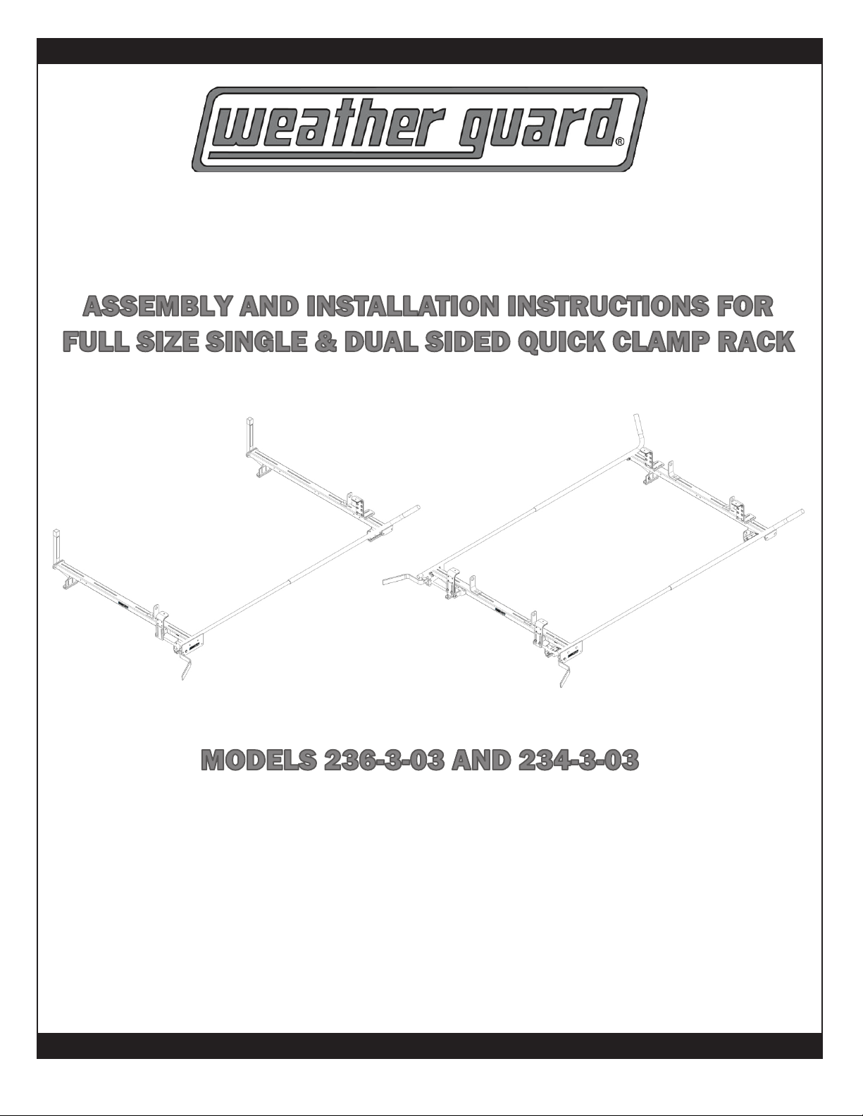
ASSEMBLY AND INSTALLATION INSTRUCTIONS FOR
FULL SIZE SINGLE & DUAL SIDED QUICK CLAMP RACK
WWW.WEATHERGUARD.COM
MODELS 236-3-03 AND 234-3-03
VAN SOLUTIONS
FOR THE WAY YOU WORK
TM
Weather Guard / Knaack 800-456-7865 (Toll Free)
420 E. Terra Cotta Ave. 800-334-2981 (Fax)
Crystal Lake, IL 60014 USA Knaack.OrderEntry@wernerco.com
Weather Guard / Knaack 888-562-2251 (Toll Free)
9133 Leslie St. Unit 105 888-456-8460 (Fax)
Richmond Hill, ON L4B4N1 Knaack.OrderEntry.Canada@wernerco.com
WWW.WEATHERGUARD.COM
*24-0308*
1
Part No. 24-00022 REV. B ECO 102669 08/16
Page 2
ATTENTION: PLEASE READ AND UNDERSTAND ALL INSTRUCTIONS AND WARNINGS
BEFORE ASSEMBLING, INSTALLING OR USING THIS PRODUCT.
BEFORE YOU BEGIN
• WEATHER GUARD ladder racks are designed to work with OEM side gutters or with WEATHER GUARD
®®
Mounting Channel kits to provide the best support for your ladders and to take advantage of OEM provided
roof mounting points. If you have not already installed the mounting channel kit to the van roof, install it now
before proceeding.
• We recommend that you use mounting channels to mount the ladder rack on to the roof due to the mounting
channels being able to distribute the load more evenly. We have provided spacers that can be used to mount
directly to the roof, but please consult the vehicle manufacturer to determine the load capacity allotted for the
roof.
• Review vehicle manufacturer’s roof mount recommendation.
• Perform the installation on a leveled surface.
• Always wear protective eyewear to keep debris out of your eyes when installing WEATHER GUARD Van
®
Products.
• All of the nylon lock nuts are torqued to 17 ft-lb when ready.
MOUNTING LONG LADDERS ON VANS
Ladders transported on a vehicle should be properly supported and the overhang of the ladders beyond
supporting points should be limited. Transporting a ladder with excessive overhang can result in reduced
ladder life. Inspect your ladder before each use. Follow ANSI 14.2-2007 for direction on securing ladders to
ladder racks.
Follow manufacturer’s guidelines for maximum allowable roof load. Do not overload the vehicle’s roof.
HARDWARE KIT
DESCRIPTION
5/16-18 x 1-3/4” SS Carriage Bolt
5/16-18 x 1-1/4” SS Carriage Bolt
5/16-18 x 7/8” SS Carriaage Bolt
5/16-18 SS Nylon Lock Nut
5/16” SS Washer
1/4-20 x 1/2” SS Taptite Screw
1/2” OD 1/8” SS Spacers
234-3-03 236-3-03
8
16
32
64
64
2
8
8
16
24
56
56
2
8
• Electric drill-driver
• 1/2” ratchet wrench
• 1/2“ and 3/8” socket
• Needle nose pliers
• Open end wrenches 7/16” and 9/16”
TOOLS REQUIRED
M8-1.25 x 40mm SS Cap Screw
4
4
2
Page 3
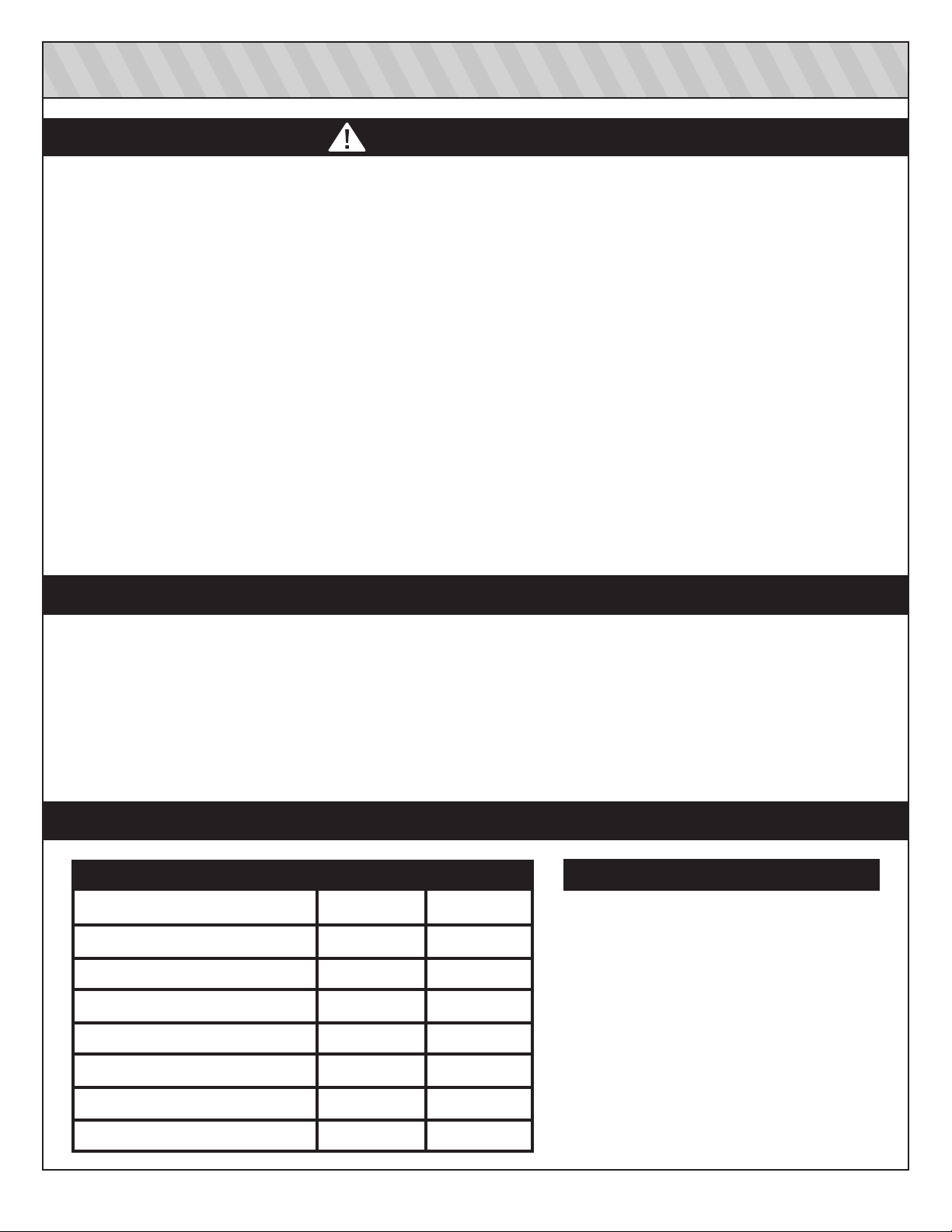
236-3-03 FULL SIZE SINGLE QUICK CLAMP RACK PARTS LIST
Vertical
Ladder Stop
Ladder Guide
Universal
Mounting Base
Mounting Foot
Bolt Plate
J- Bracket
Plate Mount
Level
Ladder Stop
Clamp
Ladder Stop
Clamp Mount
Gutter Mount
Clamp
Stud Plate
Pivot Plate
Bracket
Nylon Bearing
DESCRIPTION
Cross Member
Ladder Guide
Ladder Stop Clamp
Ladder Stop Clamp Mount
Passenger Side
Quick Clamp
Handle
QTY.
Gas Spring
Passenger Side
Front Rail
Passenger Side
Rear Rail
Gas Spring
Guard
DESCRIPTION
2
2
2
1
Front Rails
Rear Rails
Quick Clamp Handle
QC Handle Pivot Plate
QTY.
1 (PS)
1 (PS)
1 (PS)
1
Universal Mounting Base
Mounting Level Plate
Mounting Foot Bolt Plate
Curved Mounting foot Bracket
Stud Plate
4
4
4
4
4
QC Nylon Bearing
Vertical Ladder Stop
Gas Spring
Gas Spring Guard
Gutter Mount Clamp
3
2
2
1
1
4
Page 4
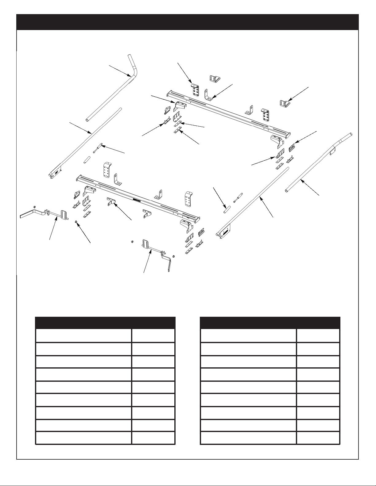
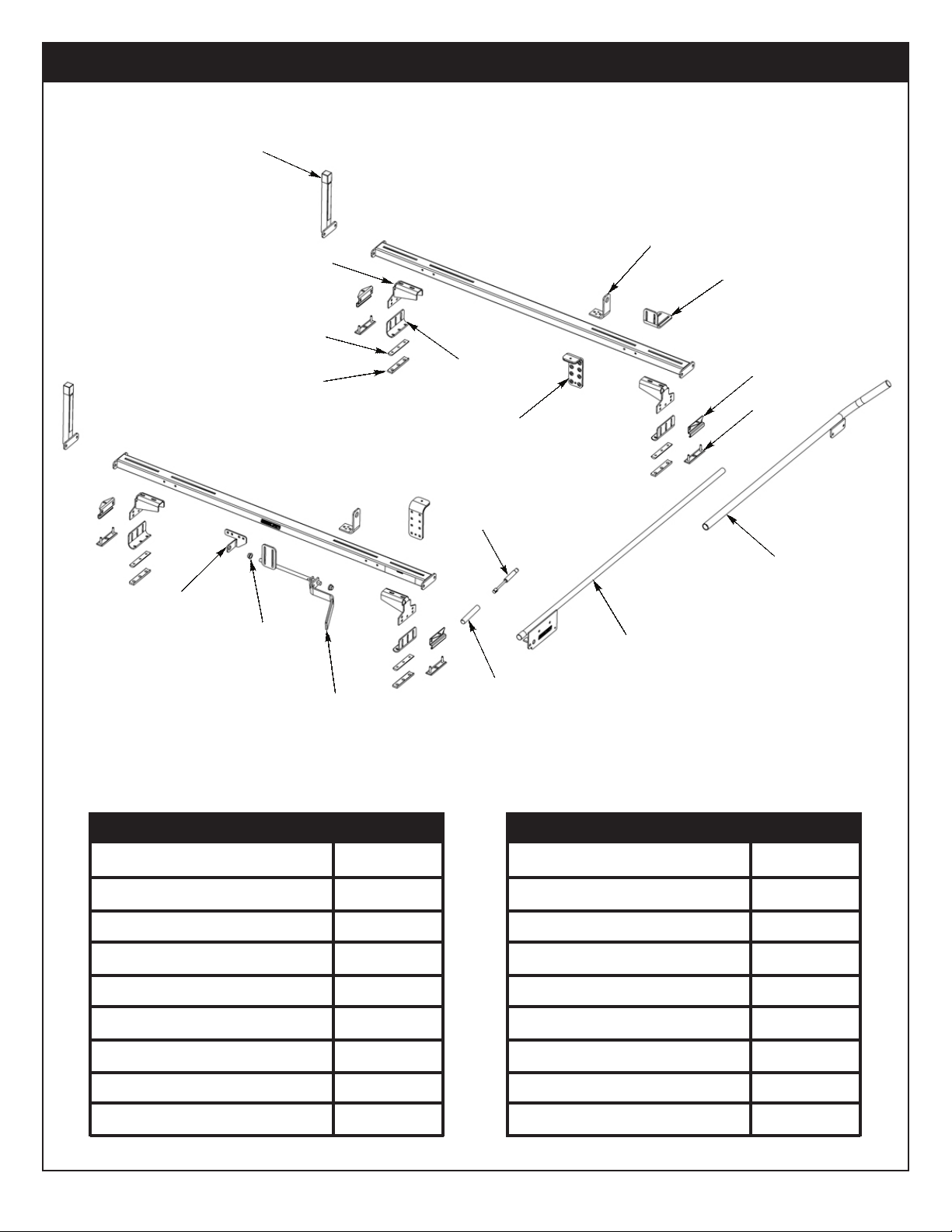
234-3-03 FULL SIZE DUAL QUICK CLAMP RACK PARTS LIST
Ladder Stop
Driver Side
Front Rail
Clamp
Driver Side
Rear Rail
Driver Side
Quick Clamp
Handle
Nylon Bearing
Universal
Mounting Base
Stud Plate
Gas Spring
Pivot Plate
Bracket
Mounting Foot
Bolt Plate
Plate Mount
Level
Gas Spring
Guard
Ladder Guide
J-Bracket
Ladder Stop
Clamp Mount
Gutter Mount
Clamp
Passenger Side
Front Rail
Passenger Side
Rear Rail
DESCRIPTION
Cross Member
Ladder Guide
Ladder Stop Clamp
Ladder Stop Clamp Mount
Universal Mounting Base
Mounting Level Plate
Mounting Foot Bolt Plate
Curved Mounting foot Bracket
Stud Plate
Passenger Side
Quick Clamp
Handle
QTY.
2
2
2
2
4
4
4
4
4
DESCRIPTION
Front Rails
Rear Rails
Quick Clamp Handle
QC Handle Pivot Plate
QC Nylon Bearing
Vertical Ladder Stop
Gas Spring
Gas Spring Guard
Gutter Mount Clamp
QTY.
DS/PS
DS/PS
DS/PS
2
4
0
2
2
4
4
Page 5
INSTALLATION INSTRUCTIONS
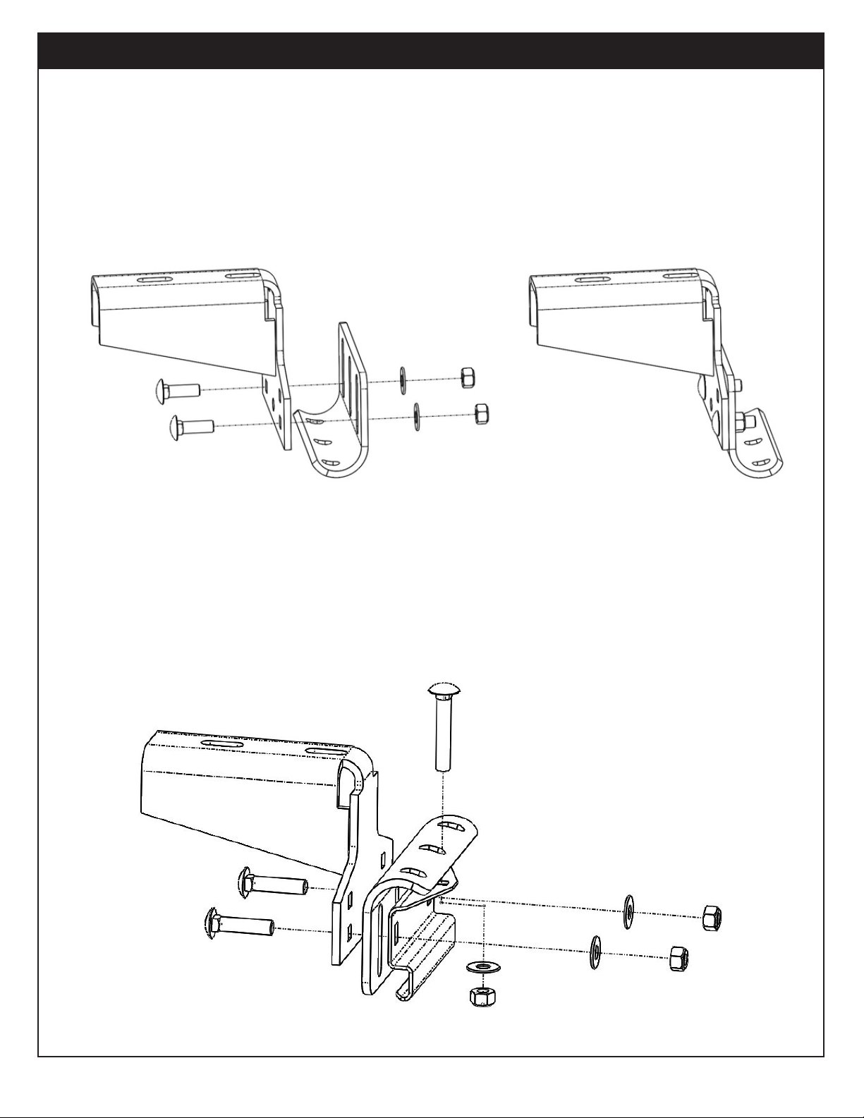
STEP 1A. LOOSELY INSTALL J-BRACKET TO UNIVERSAL MOUNTING BASE
(Ford Transit, RAM Promaster, Nissan NV, and MB Sprinter)
Using (2) 7/8” tall carriage bolts, (2) washers, and (2) nylon lock nuts.
NOTE: J-bracket can be installed in multiple configurations to result in the best fitment to your vehicle.
Bolts can be installed from both direction. Most vehicle installations will benefit from having the lowest
installed height with the mounting bracket lining up with the start of the curve on the J-bracket. Due to
vehicle roof curvatures, some adjustment for final assembly height may be required after the cross
members are installed on the roof.
VEHICLE
OR
STEP 1B. LOOSELY ASSEMBLE GUTTER MOUNT CLAMP AND J-BRACKET TO UNIVERSAL MOUNTING BASE
(GMC Savana / Chevy Express, and Ford E-Series)
Using (2) 1-1/4” tall carriage bolts, (1) 1-3/4” tall carriage bolt, (3) washers, and (3) nylon lock nuts.
NOTE: J-bracket must be installed as shown but it can be mounted on either top or bottom set of square
holes on the universal mounting base (bottom mounting position shown below).
5
Page 6

INSTALLATION INSTRUCTIONS
STEP 2. MOUNT MOUNTING FEET TO CROSS MEMBERS
Use one 7/8” carriage bolt, washer and nylon lock nut per mounting foot, Install feet to cross member,
Refer to table and diagram below for mounting foot location and orientation.
NOTE: Mounting feet can be installed in the other direction if need be (Toes in vs. Toes out).
MOUNTING FOOT DISTANCE
Ford Transit
RAM Promaster
Nissan NV
MB Sprinter
GMC Savana / Chevy Express *
Ford E-Series *
F: 58-7/8”
F: 62-7/8”
A
55-1/2”
59-5/8”
59-3/8”
53-1/4”
F: 57-7/8”
F: 60-3/4”
F: 5-1/16”
F: 3-1/16”
B
6-3/8”
5-7/8”
8-1/2”
8-13/16”
F: 5-5/8”
F: 4-1/8”
MOUNTING METHOD
WG Mounting Channel
WG Mounting Channel
WG Mounting Channel
WG/OEM Mounting Channel
Gutter Mount
Gutter Mount
* Due to the curvature of the gutter on each van, the dimensions given are a reference point.
Please make appropriate adjustments to ensure a tight and secure t, with the cross member
centered on the width of the van.
6
Page 7

INSTALLATION INSTRUCTIONS
STEP 3. INSTALL FRONT RAIL ASSEMBLY
Using (2) 1-1/4” tall carriage bolts, (2) washers, and (2) nylon lock nuts.
STEP 4. INSTALL PIVOT PLATE BRACKET ON REAR CROSS MEMBER
Using (2) 7/8” tall carriage bolts, (2) washers, and (2) nylon lock nuts.
NOTE: Mount using 2 and 4 on the passenger side. Use 1 and 3 when mounting to driver side (234-3-03).
7
Page 8

INSTALLATION INSTRUCTIONS
STEP 5. INSTALL REAR RAIL ASSEMBLY
A. Loosen the adjustable end fitting of the gas spring such that the mounting socket on either end are
facing opposite directions. Slide the gas spring guard over the gas spring as shown below.
B. Insert nylon bearings into pivot plate bracket as well as on the rear rail assembly.
C. Install handle by sliding it into the nylon bearing on the pivot plate bracket. Install gas spring onto ball
stud on the handle.
D. Slide the nylon bearing installed on the rear rail assembly onto the handle. Install gas spring onto ball
stud on the rear rail assembly.
E. Tighten rear rail assembly to rear cross member by using (2) 1-1/4” tall carriage bolts, (2) washers, and
(2) nylon lock nuts.
NOTE: For 234-3-03, install driver side front and rear assembly by following the same sequence above.
8
Page 9

INSTALLATION INSTRUCTIONS
STEP 6. INSTALL DRIVER SIDE VERTICAL LADDER STOP (236-3-03 ONLY)
Using (2) 1-1/4” tall carriage bolts, (2) washers, and (2) nylon lock nuts, fasten the vertical ladder stop.
STEP 7. RACK ASSEMBLY
With the front and the rear cross member assembly on the roof, insert the rear rail into the front rail.
Use the 1/4-20 x 1/2” taptite screws through the obround near the tip of the front rail to fasten the
rails together. Use a drop of thread locking adhesive.
NOTE: If installing a 233-3-03 Accessory Quick Clamp cross member, do not use the thread locking
adhesive yet. Refer to the 233-3-03 instruction manual.
9
Page 10

INSTALLATION INSTRUCTIONS
STEP 8. INSTALL LADDER CLAMPS
Rear Assembly
Place the ladder on the rack to adjust the clamp position fit fit your ladder.
Using (2) 7/8” tall carriage bolts, (2) washers, and (2) nylon lock nuts, fasten the rear clamp as shown.
Front Assembly
Place the ladder on the rack to adjust the clamp position fit your ladder.
Using (2) 7/8” tall carriage bolts, (2) washers, and (2) nylon lock nuts, fasten the rear clamp as shown.
Front Assembly Option 1 Front Assembly Option 2
NOTE: Use option 1 for most standard extension ladder applications and option 2 for some step ladder
applications.
10
Page 11

INSTALLATION INSTRUCTIONS
STEP 9. INSTALL LADDER GUIDES
Place the ladder on the rack to adjust the ladder guide position fit fit your ladder.
Using (2) 1-1/4” tall carriage bolts, (2) washers, and (2) nylon lock nuts, fasten the ladder guide.
STEP 10A. MOUNT CROSS MEMBERS TO VEHICLE - (Ford Transit, Nissan NV, and MB Sprinter)
Slide two stud plates per mounting channel if not already done. Lift the assembled ladder rack and
place it on the stud plates on all four corners . Use (2) washers, (2) nylon lock nuts, and a bolt plate
to fasten each mounting foot.
11
Page 12

INSTALLATION INSTRUCTIONS
STEP 10B. MOUNT CROSS MEMBERS TO VEHICLE - (GMC Savana / Chevy Express, and Ford E-Series)
Make sure that the gutter is clamped between the gutter clamp and the inverted J-bracket.
Gutter Position
Position the cross member to desired position and tighten the two nuts to 17 ft-lb. Vertically constrain
the inverted J-bracket and the gutter clamp using one 1-3/4” carriage bolt, washer, and a nut.
STEP 10C. MOUNT CROSS MEMBERS TO VEHICLE - (RAM Promaster)
The 2113-0-01 or 2115-0-01 mounting channel kits are used on RAM Promaster vans. For 159”
wheel-base and the 159” wheel-base extended versions as well as 136” wheel-base with the
2113-0-01 mounting channel kit, the rear cross member is mounted directly to the rear-most
mounting point on the roof. The front cross member and the center cross member (if used), mount
to the channels as shown in step 10A.
2
6
1
3
1. Rotate roof cleat 90°
2. Place stud plate over cleat.
3. Rotate roof cleat back to the original position.
4. Place channel over studs.
5. Place brackets over the channel.
6. Retain with 5/16-18 nut and washer.
4
5
STEP 11. TIGHTEN DOWN ALL HARDWARE
Make sure everything is aligned and installed properly and torqued to 17 ft-lb.
12
Page 13

SERVICE PARTS
PART NO.
7870
7707
2070-3-01
7830-3-01
7577-3-01
7831-3-01
7578-3-01
70514
72213
72214
DESCRIPTION
Ladder Guide
Ladder Stop Clamp
70” Cross Member & Mounting Feet
Passenger Side Front & Rear Rail
Passenger Side Handle
Driver Side Front & Rear Rail
Driver Side Handle
Vertical Post
Rear Handle Pivot Plate Bracket
Bolt Kit AP
72215
72216
72217
Bolt Kit QC
Bolt Kit 125
Gutter Clamp Kit
13
Page 14

WARNING
This product can reduce the driver’s ability to clearly see roadways, vehicular or pedestrian traffic and other objects through the rear and
side windows of the vehicle, which can cause an accident. Extra precautions should be taken when driving a vehicle with this product. Make
all adjustments necessary to ensure maximum visibility, including but not limited to, changing mirror and seating positions. State and local
laws may prohibit obstruction of windows in a moving vehicle.
These instructions are to be followed using the parts and fasteners supplied for proper installation. Any modifications or improper installation
of this product will create a hazardous condition that could result in death, serious personal injury and/or property damage.
CAUTION
Prior to drilling, so as not to cut electric wires, fuel lines, brake lines, etc., check behind and underneath drilling and mounting locations. To keep
debris out of your eyes when checking the underside of the vehicle, or when drilling, always wear protective eye wear. Failure to heed this warning
will result in death or serious injury.
– NOTICE –
Any modification or unintended use of this product shall imediately void all manufacturers warranties. Manufacturer disclaims all liability for injuries
to persons or property resulting from any modification to, or unintended use of this product.
KNAACK LLC LIMITED LIFETIME WARRANTY FOR WEATHER GUARD® PRODUCTS
WEATHER GUARD® Products — Limited Lifetime Warranty
(Purchased on or after 1/1/2009)
®
Knaack LLC (the “Manufacturer”) warrants to the original purchaser only that WEATHER GUARD
(the “WEATHER GUARD
the WEATHER GUARD
terminates if the original purchaser transfers the WEATHER GUARD
What is Covered
All WEATHER GUARD
What We Will Do to Correct Problems
Subject to the limitations and exclusions described in this limited warranty, the Manufacturer will remedy defects in materials or workmanship by providing
one of the following remedies at its option and
®
GUARD
Product or (b) replacing the entire WEATHER GUARD® Product. In addition, the manufacturer may elect at its option, not to repair or replace the
WEATHER GUARD
be used toward the purchase of new WEATHER GUARD
What is Not Covered
This limite
No
This Limited Lifetime Warranty is the sole and exclusive warranty for WEATHER GUARD
alter this warranty or make any other warranty on behalf of Knaack LLC.
Noti
If the WEATHER GUARD
discovery of the nonconformity. In order to receive the remedies under this limited warranty, the warranty claim must describe the nature of the nonconformity, and
a copy of the original sales receipt, invoice, bill or other proof of purchase must accompany the claim. Repairs or modificatio ns made to the WEATHER GUARD
Product by ot
the owner ’s compliance with these required notification and repair procedures. Warranty claims must include reciprocal contact information and may be made via
certified mail to:
d warranty expressly excludes:
• Defects caused by normal wear and tear, cosmetic rust, scratches, accidents, unlawful vehicle operation, or modification to the product, or any types or
repair of a WEATHER GUARD
• Defects resulting from conditions beyond the Manufacturer’s control including, but not limited to misuse, overloading, or failure to assemble, mount or use
the WEATHER GUARD
made available to the original purchaser.
• Damage to the contents of the box or vehicle.
• TO THE EXTENT PERMITTED BY LAW, IN NO EVENT SHALL THE MANUFACTURER BE LIABLE FOR ANY INCIDENTAL, SPECIAL, INDIRECT,
OR CONSEQUENTIAL DAMAGES, INCLUDING ANY ECONOMIC LOSS, WHETHER RESULTING FROM NONPERFORMANCE, USE, MISUSE OR
INABILITY TO USE THE WEATHER GUARD
Other Express Warranty Applies
cation Pro cedures
her than the Manufacturer or its authorized agent will nullify this limited warranty. Coverage under this limited warranty is conditioned at all times upon
®
Product”) will be free from defects in material and workmanship from the date of purchase and continuing for the expected life time of
®
Product. A copy of the original sales receipt must be supplied to the Manufacturer at the time a warranty claim is made. This warranty
®
Products identified above that are purchased on or after January 1, 2009.
without charge to the original purchaser for parts or labor: (a) repairing the defective portion of the WEATHER
®
Product, but rather issue to the original purchaser a refund equal to the purchase price paid for the WEATHER GUARD® Product or a credit to
®
Product other than those authorized or provided by the Manufacturer.
®
Product in accordance with the Manufacturer’s written instructions or guidelines included with the WEATHER GUARD® Product or
®
Product does not conform with the terms of this limited warranty, the original owner must promptly notify the Manufacturer in writing upon
®
Product.
®
PRODUCT OR THE MANUFACTURER’S NEGLIGENCE.
®
Product to any other person.
Knaack LLC
ATTN: Warranty Claims
420 E. Terra Cotta Avenue Crystal Lake, IL 60014
Truck and Van Products
®
products. No employee, agent, dealer, or other person is authorized to
®
*24-0308*
If you have any questions, please call toll free at 1-800-456-7865
©2016 Knaack LLC
14
Part No. 24-00022 REV. B ECO 102669 08/16
 Loading...