

Page 1
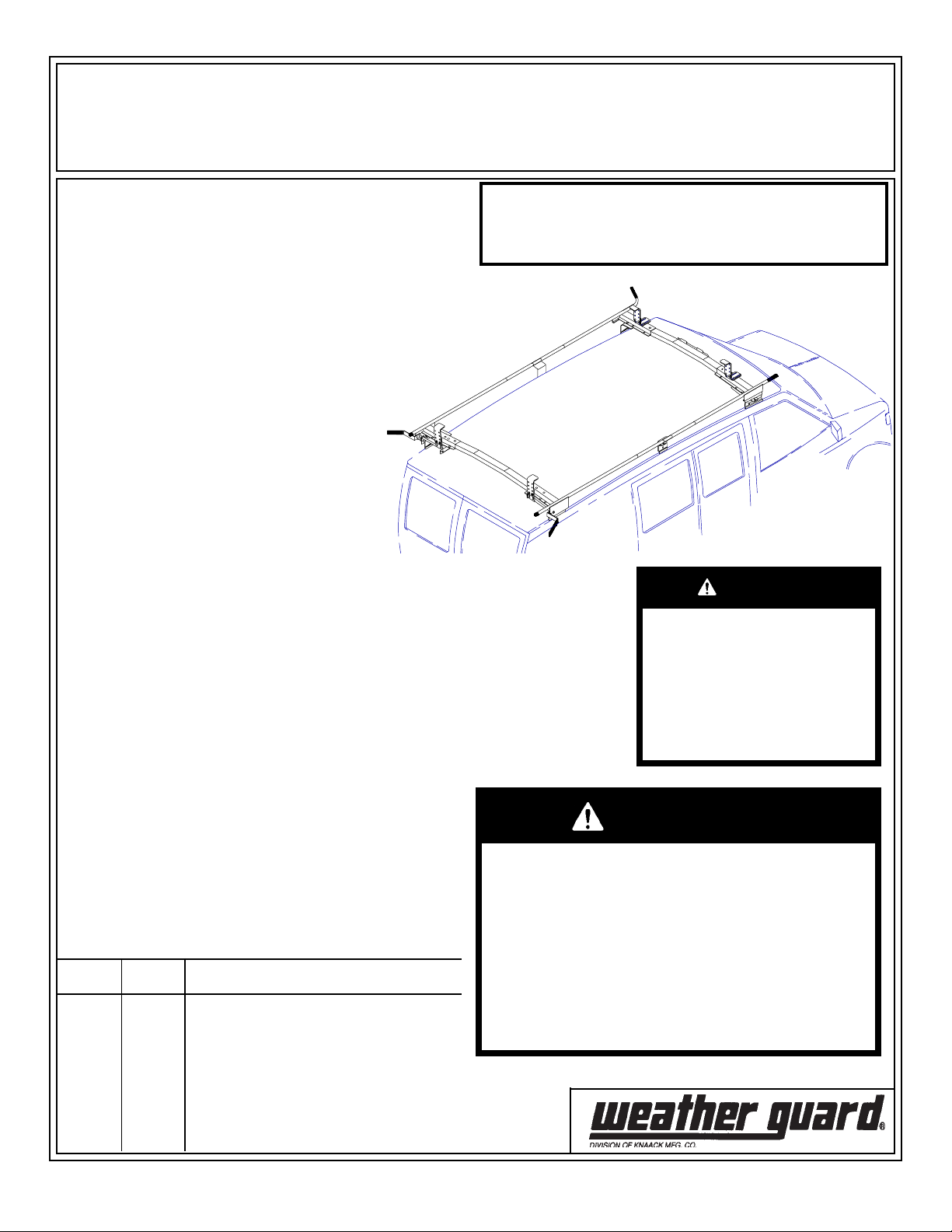
ASSEMBLY AND INSTALLATION INSTRUCTIONS
Models 234 / 236
(Model 236, Curbside clamping only Model 234, Streetside and Curbside clamping)
IMPORTANT
BEFORE YOU BEGIN
Read these instructions and
warnings completely before
assembly and installation.
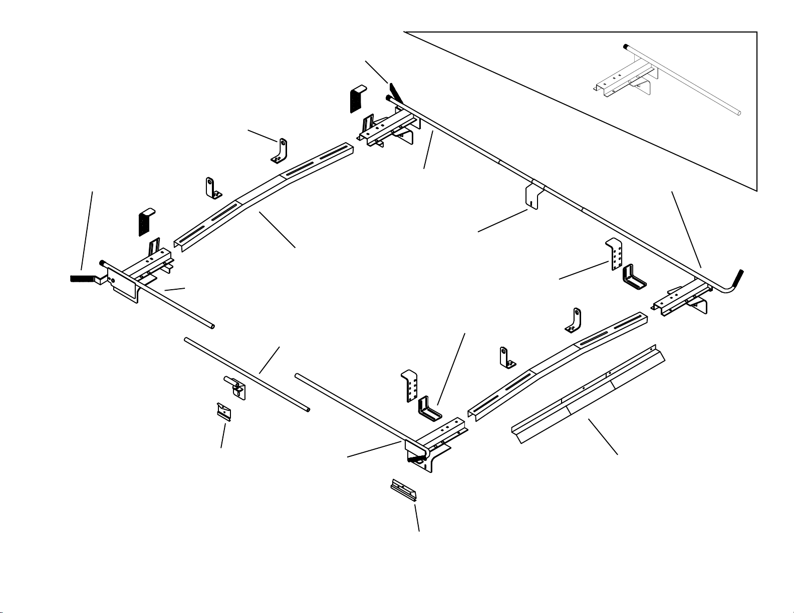
234 / 236 PARTS LIST
2- Crossmembers
4- Ladder Guides (234)
2- Ladder Guides (236)
4- Top Adj. Clamp (234)
2- Top Adj. Clamp (236)
2- Bottom Adj. Angle (234)
1- Bottom Adj. Angle (236)
1- P.S. Rear Ass'y.
1- D.S. Rear Ass'y. (236)
1- D.S. Rear Ass'y. (234)
1- P.S. Front Ass'y.
1- D.S. Front Ass'y.
1- Airfoil
4- 8" Mtg. Clamps
2- 4" Mtg. Clamps
1- Bulk Cushion Strip
2- Center Support
2- Center Rails
Approximate Assembly and Installation time:
234: 1 hour 20 min. per unit (1.3 hrs.)
236: 1 hour 12 min. per unit (1.2 hrs.)
Depending on van equipment installation experience
The distinctive, trademarked
RED TIPS are your assurance of
WEATHER GUARD® Equipment
quality.
TOOLS REQUIRED
Ruler
3/8" Socket
Ratchet Wrench
3" Socket Extension
Loctite® thread locker
Electric Drill w/ 5/16" & 3/8" drill bits
7/16" Open or Box End Wrench (2)
1/2" Socket (deep well preferred)
WARNING
These Ladder Racks were
not designed to fit Chrysler
minivans. If installed on
these vehicles, the handle
can cause serious head
injuries or property damage.
BOLT KIT
Bolt Kit #32-0159 with Model 236 and Bolt Kit
#32-0157 with Model 234. Check these bolt
kits to be sure the following parts are included:
32-0159 32-0157 Description
4 4 1/4-20 x 1/2" Taptite Screw
3 3 1/4-20 x 3/4" Hex Hd. Bolt
33 42 5/16" Flat Washer
4 6 5/16-18 x 1-1/4" Carriage Bolt
25 32 5/16-18 x 7/8" Carriage Bolt
33 42 5/16-18 x Nylon Lock Nut
3 3 1/4-20 Nylon Lock Nut
6 6 5/16-18 x 2" Carriage Bolt
WARNING
This product is only intended for, and only safe
for, transporting ladders, lumber, pipe and other
similar materials. It is the responsibility of the
user to secure these materials to the rack before
transporting. Any modifications made to this product, or use of this product for any other purpose
than its intended use, could create a hazardous
condition that can cause serious personal injury
or property damage.
Rev.A 4/04 Part No. 24-0181
Page 2
2
DS Handle
DS Handle
Ladder Guide
PS Rear
Crossmember
Center Rail
234
DS Rear
Center Support
Bottom Adj Angle
236
DS Rear
DS Front
Top Adj Clamp
4" Mtg Clamp
Figure 1. Parts Identification
PS Front
Airfoil
8" Mtg Clamp
Page 3
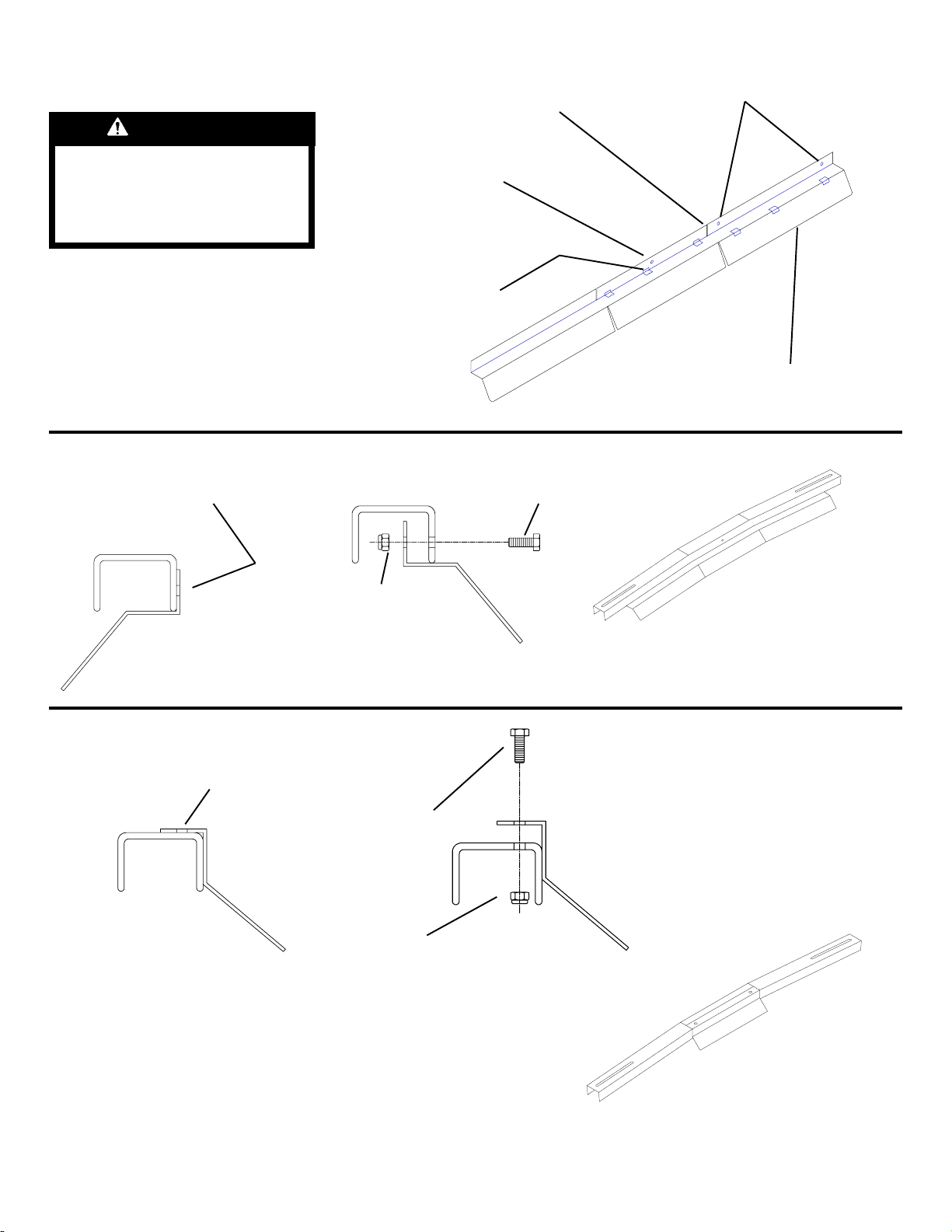
1. Airfoil to Front Crossmember Assembly
CAUTION
Cut off Dodge Airfoil
straight through notch
and remove burrs
Dodge mounting holes
To keep debris out of your
eyes when drilling, always
wear protective eyewear.
If mounting a Conduit Carrier
remove appropriate knockouts for "U"
Clamp mounting clearance.
Center the Airfoil side to side on the
Crossmember. Mark the center
mounting hole and drill a 5/16" hole.
Ford / GM mounting
this hole only
Figure 2. Airfoil
1/4-20 Nylon
Lock Nut
Use this portion for Dodge vans only.
All other vans use entire Airfoil.
1/4-20 x 3/4"
Hex Hd. Bolt
Airfoil is to face forward.
Figure 3. Ford / GM Front Crossmember to Airfoil marking/fastening
Center the Airfoil side to side on the
Crossmember. Mark the mounting
holes on the top and drill the 5/16"
holes.
1/4-20 x 3/4"
Hex Hd. Bolt
1/4-20 Nylon
Lock Nut
Airfoil is to face forward.
Figure 4. Dodge Ram Front Crossmember Airfoil marking/fastening
3
Page 4

4
2. Rack Assembly
1996 and newer Chevy GMT 600/GMC
Savana use these two holes
(Ford/Dodge mounting holes
shown in use).
5/16-18 x 7/8"
Carriage Bolt
NOTE: If installing a Model 233, assemble it at this time, and use it in
place of the Center Supports.
5/16-18 x 7/8"
Carriage Bolt
5/16" Flat Washer and
5/16"-18 Nylon Lock Nut
Not used on Chevy
GMT600/GMC
Savana vans, use
only two bolts
through the Bottom
Adj. Angle.
NOTE:
See Figure 11.
before assembly
Align Center Rail holes, with holes
in both front and rear rails, then
fasten (repeat on opposite side).
Use a drop of Loctite
1/4-20 x 1/2" Taptite screws.
NOTE:
Holes have been predrilled in the rails to allow for
the adjustment of the rack to the length that best fits
what is needed. (80-1/16", 93-5/16", 105-9/16")
These dimensions are center to center on the stands.
Figure 5. Side Rail / Crossmember / Center Rail / Center Support Assembly
Center Rail
5/16-18 x 1-1/4"
Carriage Bolt
® on the
Loosely tighten fully
seated Crossmembers.
Repeat the procedure
on the opposite side.
5/16" Flat Washer and
5/16"-18 Nylon Lock Nut
Page 5

3. Mounting Cushion Installation
Mounting Cushion (cut from bulk)
cut to length and wrapped around
each Stand and Center Support.
Figure 6. Mounting Cushion Installation
4. Adjust the stands to the approximate gutter width dimensions below.
With the help of others, lift the rack
and position it on the vehicle. For
proper clamping on all vans except
the 1996 and newer Chevy GMT600/
GMC Savana, locate the stands as
close as possible to the roof. Make
sure the Crossmembers are centered
between the stands before tightening
the Crossmember/Socket bolt.
Figure 7. Breaking spot weld
8"
MAX
NOTE: If van has a sliding door
with a guard, it may be necessary
to remove and notch the guard to
accept the mounting clamp. If the
guard is spot welded, simply place
the blade of a common screwdriver
at the weld and strike with a hammer. This will give the guard flexibility to insert the Clamp
under the rain gutter.
8" Max dimension is from the rear
edge of the rear Stand to the rear
of the gutter.
Approximate Gutter Widths
Front Center Rear
Ford 64-1/4" 64-1/4" 62-3/4"
Dodge 65-1/4" 64-7/8" 64-1/2"
GM* 66-1/8" 66-3/4" 64-3/4"
GM** 58-3/4" 58-3/4" 57-3/8"
* - 1996 and older GM vans
** - 1996 and newer Chevy GMT600/
GMC Savana vans
Figure 8. Rear Stand Location
5/16-18 Carriage Bolt
GM van use 1-1/4" long bolt
Ford or Dodge van use 2" long bolt.
5-16" Flat Washer and
5/16"-18 Nylon Lock Nut
5/16-18 x 2"
Carriage Bolt
5-16" Flat Washer and
5/16"-18 Nylon Lock Nut
Figure 9. Clamp Installation
5/16-18 x 7/8"
Carriage Bolt
5
Page 6

5. Airfoil to Socket Drilling and Fastening
Drill 5/16" holes in Airfoil using
holes in socket flange as a
guide.
NOTE: Be careful not to thrust the
drill into the vehicle roof. A block of
wood held under the Crossmember
will help avoid this.
1/4 -20 Nylon Lock Nut
6. Loosely fasten the Top Adj. Clamp
to the Front and Rear Assemblies. To
adjust Clamps, place the ladder on
the rack (Figure 13.), and adjust the
clamps forward or back / up or down
to capture the nearest ladder rung.
Tighten the bolts.
5/16" Flat Washer and
5/16"-18 Nylon Lock Nut
1/4-20 x 3/4"
Hex Hd. Bolt
Figure 10. Airfoil/Socket
5/16" Flat Washer and
5/16"-18 Nylon Lock Nut
This application is used for
standard Extension ladders.
5/16-18 x 7/8"
Carriage Bolt
5/16-18 x 7/8" Carriage Bolt
Figure 11. Rear DS Clamp
This application will be needed
for Dead-head ladders and
some Step ladders.
6
Figure 12. Front DS Clamp
Page 7

CAUTION
Load should be approximately centered
front to rear. Failure to do this will cause
damage to the vehicle roof. Long loads
that extend out the rear of the vehicle will
prevent the rear hatch from fully opening
and cause damage if attempted.
9. Assemble the Ladder Guides
through the slots of the Crossmembers
and slide up to the ladder. Tighten the
Fasteners.
5/16-18 x 7/8"
Carriage Bolt
Figure 13. Clamp Adjustment
CAUTION
To keep debris out of your
eyes when drilling, always
wear protective eyewear.
WARNING
Ladders must be secured per
ANSI standard A142.2-1990
paragraph 8.4.4. Ladder damage will occur from road shock
and vehicle vibration if the ladder is not properly secured to
the ladder rack. Bouncing and
side to side motion of an improperly secured ladder will
cause wear and weaken the
ladder. Using a damaged ladder could lead to a structural
collapse and could result in a
serious injury or death.
5/16" Flat Washer and
5/16"-18 Nylon Lock Nut
Figure 14. Ladder Sway Brace
7
Page 8

WEATHER GUARD® PRODUCT
REFINISHING PROCEDURES
All WEATHER GUARD® products are
finished with a polyester powder coating, and it
is important to follow these procedures to get
proper adhesion. As Knaack Manufacturing Co.
cannot control the finishing of the products, the
warranty for WEATHER GUARD® products on
paint is not applicable on refinished products.
1. Sand the surface to be painted with 180-200
grit sand paper to rough up the surface. This
should be followed by wet sanding with a 400 grit
wet or dry paper.
2. Wipe down the sanded surface with ketone
based thinner. This removes the dust and
softens the powder coating for better paint
adhesion.
3. Wipe sanded area with a tack rag to remove
loose dust and particles before painting.
NOTE: Do not use a lacquer over the
powdered coating.
- NOTICE -
Any modification or unintended use of this product shall immediately void all manufacturers warranties.
Manufacturer disclaims all liability for injuries to persons or property resulting from any modification to, or
unintended use of this product.
If you have any questions, please give us a call. Call Toll Free 1-800-456-7865
U.S. - 4618083, 5829654, 842268, 1661625, 1663369, 1750034, 2228051, 2362167; Canada - 1235100, 282725; U.K. - 1400720;
WEATHER GUARD® products are protected by one or more of the following patents or trademarks:
N.Z. - 296049; Aus. - 761964; other patents and trademarks pending.
KNAACK MANUFACTURING COMPANY
420 E. TERRA COTTA AVENUE - CRYSTAL LAKE, ILLINOIS, USA 60014 - 815-459-6020
©2004 Knaack Manufacturing Company
 Loading...