

Page 1
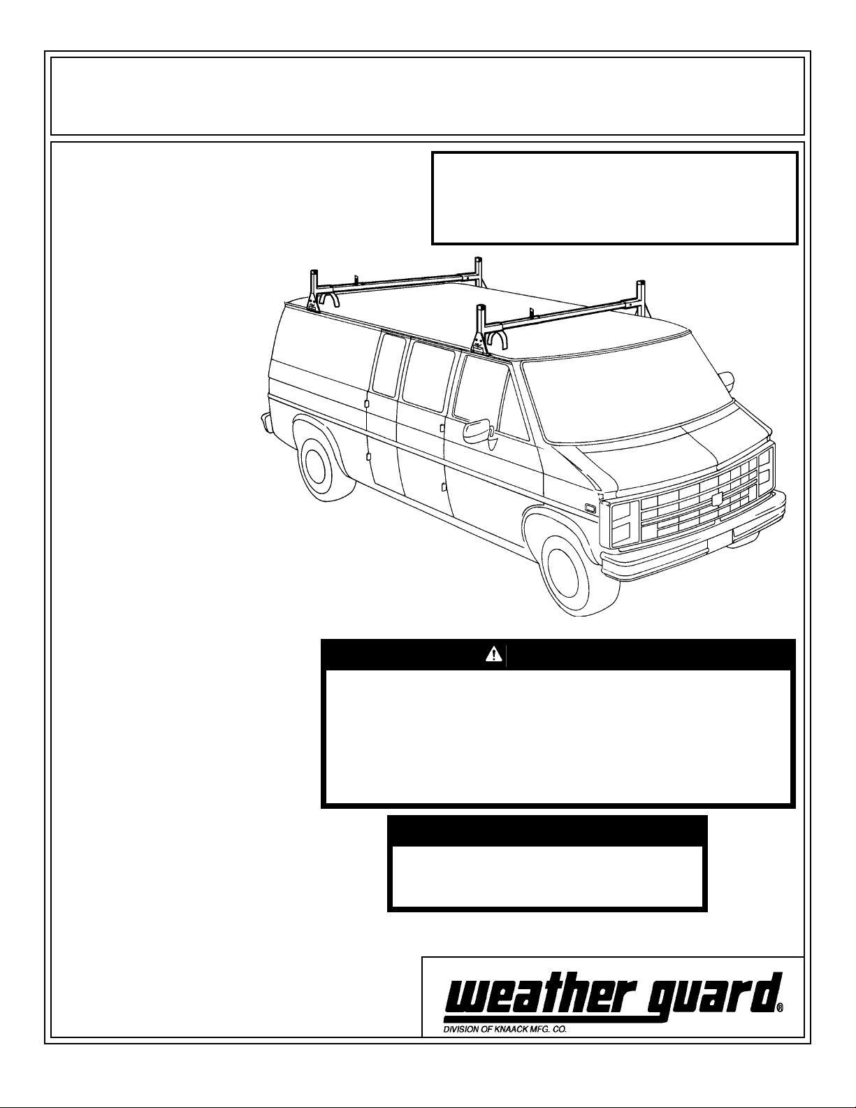
ASSEMBLY AND INSTALLATION INSTRUCTIONS
All Purpose Rack - Models 209 • 219 • 229 • 2095 • 2097
IMPORTANT
BEFORE YOU BEGIN
Read these instructions and
warnings completely before
installation.
The distinctive, trademarked
RED TIPS are your assurance of
WEATHER GUARD® Equipment
quality.
NOTE: We have found varying
tolerances between the top of
the doors and the rain gutters
on the 1992 and newer full-size
vans. Before placing van rack on
vehicle, check the door clearance with the bottom clamp, by
holding it to the underside of the
rain gutter and slowly opening
the door. If the door hits, you
will have to move the clamp to
where more clearance is available. Some cases may require
moving the clamps rearward of
the driver and passenger side
doors.
Approximate Assembly and Installation time:
209: 42 min. per unit (.7 hrs.)
219 & 229: 48 min. per unit (.8 hrs.)
2095 & 2097: 21 min. per unit (.35 hrs.)
Depending on van equipment installation experience
Figure 1. Typical Installation.
WARNING
This product is only intended for, and only safe for, transporting
ladders, lumber, pipe and other similar materials. It is the responsibility of the user to secure these materials to the rack before
transporting. Any modifications made to this product, or use of
this product for any other purpose than its intended use, could
create a hazardous condition that can cause serious personal
injury or property damage.
TOOLS REQUIRED
• 7/16" Open or Box End Wrench (2)
• 1/2" Open or Box End Wrench
• Electric Drill
• 5/32" & 5/16" Drill Bits
• Scissors or Utility Knife
• 5/16" Open End Wrench
• Loctite® thread locker
• Hacksaw
• Pencil
• Ruler
CAUTION
Load should be approximately centered
front to rear on all vehicles. Failure to do
this will cause damage to the vehicle roof.
Rev. A 5/05 Part No. 24-0166
Page 2
BOLT KITS
The following bolt kits are provided with each model. Check
the bolt kit to be sure the following parts are included:
Model 209 2095 219
2097 229 Description
Bolt Kit 32-0178 32-0179 32-0180
Quan. 8 4 12 1/4-20 x 2-1/2" Hex Hd. Bolt
8 4 1 2 1/4-20 Nylon Lock Nut
2 8 1 4 4 2 5/16" Flat Washer
1 2 6 18 5/16-18 Nylon Lock Nut
8 4 1 2 5/16-18 x 7/8" Carriage Bolt
4 2 6 5/16-18 x 1-1/2" Carriage Bolt
6 0 6 #10 x 1/2" Sheet Metal Screw
PARTS LIST
209 219 229 2095 2097 Description
4 6 4 2 0 Stand
0 0 2 0 2 Center Stand (Ford/GM)
2 3 3 1 1 Crossmember
4 6 6 2 2 Stand Clamp
1 1 1 0 0 Airfoil
2 3 3 1 1 Ladder Guide
1 1 1 1 1 Bulk Cushion Strip
2 2 2 0 0 Ladder Strap
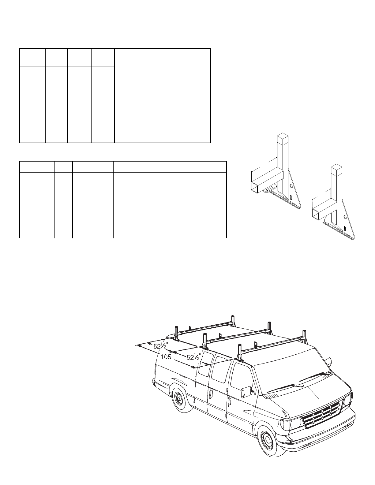
NOTE: Models 229 and 2097 are used
exclusively on 1992 or newer Ford and
1996 or newer Chevy GMT600/GMC
Savana vans. As shown in
below, the front and rear stands (A)
have 7" long sockets. The center
stands (B) have 5" long sockets that
are 5/8" lower to compensate for the
upward bow in the center of the Ford/
GM gutters.
7"
Figure 2.
5"
A
B
NOTE: 1992 or newer Ford and 1996 or
newer Chevy GMT600/GMC Savana vans
have an upward bow in the center of the
gutter. When installing a three crossmember van rack, we suggest using the
dimensions shown in
surements are from center to center of the
stands. Be sure to remember if a third
(center) crossmember is used; it can be
identified by the 5" socket (
shown in Figure 2.
The preferred rack placement will locate the
rear of the front stands even with the rear edge
of the front doors. The van rack placement on the
roof can vary somewhat, and the dimensions (
in Figure 3.
) may vary due to variations in the gutter bow.
Figure 3
. All mea-
Stand B as
) for the Ford and GM.
shown
Figure 2. Center Stand Identification
2
Figure 3. Stand Placement Dimensions
Page 3

Stand
Upright
Tube
Ladder Guide
1/4-20 x 2-1/2"
Hex Hd. Bolt
Airfoil
Socket
Stand
8" Cushion
Strip
ASSEMBLY INSTRUCTIONS
1. Cut 8" Cushion Strips from the Bulk
Cushion Strip to fit the gutter lip of
each Stand. Press onto the underside
of each Stand to prevent scratching
your vehicle.
NOTE: Gutter widths vary, some vans
will require the Crossmember to be cut.
All Crossmembers for 1996 or newer
Chevy GMT 600/GMC Savana vans will
have to be cut to length, as well as the
rear Crossmember on a 1992 or newer
Ford van. Insert each Crossmember
end into a Stand. Carefully place each
Crossmember/Stand in position (see
Figure 3.), laying the Crossmember on/
across the roof. On the opposite side of
the van from the Stands, place a Stand
in the gutter so the Stand socket is
alongside of the Crossmember. Raise
the Crossmember end off the roof so
that it and the Stand socket are horizontal. Mark the Crossmember 1" short
of the Stand upright tube. Remove the
Stand and Stand/Crossmember from
the van. Cut the Crossmember end off
at the mark.
CAUTION
To keep debris out of your
eyes when drilling, always
wear protective eyewear.
5/16" Flat
Washer
5/16" Holes
Crossmember
5/16" Flat
Washer
5/16" Flat
Washer
1/4-20 Nylon
Lock Nut
1/4-20 Nylon
Lock Nut
Ladder
Strap
5/16" Flat
Washer
1"
Figure 6. Rack Assembly
2. Measure and mark the center of the
Crossmembers. Insert each Crossmember end into a Stand Socket.
Place the Front Stand/Crossmember
Assembly on the van with the Stands
resting in the roof gutters, and the rear
of the front Stands even with the back
edge of the front van doors (
3
.). Place the other Stand
assembly(s) where shown in
Center the Crossmembers between the
Stand Sockets. To provide maximum
strength and proper clamping, on all
vans except the ’96 or newer Chevy
GMT600/GMC Savana, locate the
Stands as close as possible to the
roof. Mark the Crossmembers at the
socket ends. Remove the rack.
See Figure
Figure 3
.
5/32"
Pilot Hole
Figure 4. Airfoil Installation
5/16"
Hole
5/16-18 x 7/8"
Carriage Bolt
5/16" Flat
Washer and
5/16-18 Nylon
Lock Nut
5/16-18 x 1-1/2"
Carriage Bolt
Mark the center
of the obround
Figure 5. Airfoil Marking
#10 x 1/2" Sheet
Metal Screw
1/4-20 x 2-1/2"
Hex Hd. Bolt
5/16" Flat
Washer and
5/16-18 Nylon
Lock Nut
Clamp
3
Page 4

3. Center the Airfoil on the Front Stand
Assembly Crossmember, keeping the
bend of the Airfoil even with the top of
the Crossmember (
See Figure 4.
).
Mark all six mounting slots in the
center of the radius at the top of the
slots (
See Figure 5.
). Drill these
locations with a 5/32" drill bit. Place a
drop of Loctite® thread locker
(customer supplied) on each screw.
Install each screw half way, then place
the Airfoil on the Crossmember over the
screws and slide it downward. With the
screws now in the upper portion of the
slot, and flush with the top of the
Crossmember, tighten the screws. The
Airfoil will face forward when installed.
4. With the Crossmembers inserted
into the Sockets to their marks, drill
completely through the Socket/Crossmembers, centered vertically on the
socket tube 1" in from the open end.
Fasten together.
5. Replace the rack assemblies back
in place on the van roof, and install the
Clamps.
Figure 7. Breaking Weld
NOTE: Some vans have covers over the
sliding door track, spot welded in place
(
See Figure 7.
). If the Clamp will not fit
between the spot welds, place a flat
screwdriver at the restricting weld and
strike it with a hammer to break the
weld. This will give the guard flexibility
to insert the clamp under the rain gutter.
NOTE: Be careful not to thrust the
drill into the vehicle roof. A block of
wood held under the Crossmember
will help avoid this.
6. Place the Ladder Stops on the
Crossmembers centered side to side
up to the ladder side. Mark the Ladder
Stop mounting holes. Drill 5/16" holes.
Fasten the Ladder Stops to the
Crossmembers. (
See Figure 6.
)
7. Adjust the Airfoil to eliminate wind
noise by bending it downward to the
following dimensions:
'96 or newer Dodge:
1/2" above roof at center
1-1/4" above roof at each end
'96 or newer Ford:
1/2" above roof at center
1-3/8" above roof at each end
'96 or newer
Chevy GMT600/GMC Savana:
2-1/4" above roof at center
3-3/16" above roof at each end
NOTE: These dimensions are guidelines, it may be necessary to adjust
the Airfoil further.
WARNING
Ladders must be secured per
ANSI standard A142.2-1990 paragraph 8.4.4. Place and secure the
ladder so that a rung is against
the ladder stop. Ladder damage
will occur from road shock and
vehicle vibration if the ladder is
not properly secured to the ladder rack. Bouncing and side to
side motion of a improperly secured ladder will cause wear and
weaken the ladder. Using a damaged ladder could lead to a
structural collapse and could result in a serious injury or death.
WEATHER GUARD®
REFINISHING PROCEDURES
All WEATHER GUARD® products are
finished with a polyester powder coating, and it is important to follow these
procedures to get proper adhesion. As
Knaack Manufacturing cannot control
the finishing of the products, the warranty for WEATHER GUARD® products on paint is not applicable on
refinished products.
1. Sand the surface to be painted with
180-200 grit sand paper to rough up the
surface. This should be followed by wet
sanding with a 400 grit wet or dry paper.
2. Wipe down the sanded surface with
ketone based thinner. This removes the
dust and softens the powder coating for
better paint adhesion.
3. Wipe sanded area with a tack rag to
remove loose dust and particles before
painting.
NOTE: Do not use a lacquer over
the powdered coating.
- NOTICE -
Any modification or unintended use of this product shall immediately void all manufacturers warranties.
Manufacturer disclaims all liability for injuries to persons or property resulting from any modification to, or
unintended use of this product.
If you have any questions, please give us a call. Call Toll Free 1-800-456-7865
WEATHER GUARD® products are protected by one or more of the following trademarks: U.S. - 842268, 1661625, 1663369, 1750034, 2228051,
2362167; Canada - 282725; U.K. - 1400720; N.Z.- 296049; Aus. - 761964 other trademarks pending.
KNAACK MANUFACTURING COMPANY
420 E. TERRA COTTA AVENUE-CRYSTAL LAKE, ILLINOIS, USA 60014
815-459-6020
©2004 Knaack Manufacturing Company
 Loading...