

Page 1
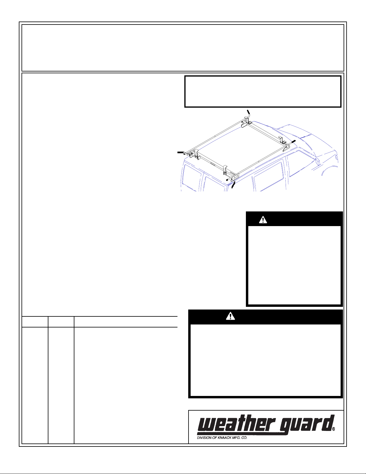
ASSEMBLY AND INST ALLATION INSTRUCTIONS
Model 223 & 224 Quick Clamp Van Racks
(Model 223, Curbside clamping only • Model 224, Streetside and curbside clamping)
IMPORTANT
BEFORE YOU BEGIN
Read these instructions and
warnings completely before
assembly and installation.
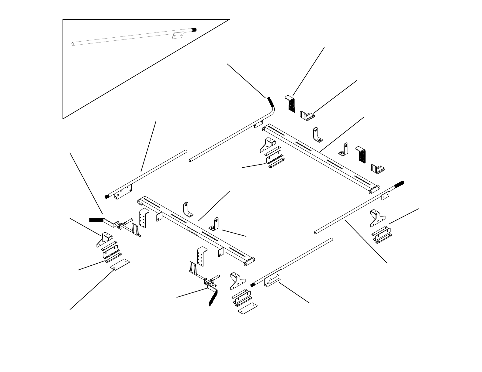
223 / 224 PARTS LIST
• 4- Clamp Bar
• 4- Mounting Bracket
• 1- Front Crossmember w/ Airfoil
• 1- Rear Crossmember
• 2- Ladder Guide (223)
• 4- Ladder Guide (224)
• 2- Top Adjustable Clamp (223)
• 4- Top Adjustable Clamp (224)
• 1- Bottom Adjustable Angle (223)
• 2- Bottom Adjustable Angle (224)
• 4- Stand
• 1- Passenger Side Front Rail
• 1- Driver Side Front Rail
• 1- P.S. Rear Rail w/ handle plate
• 1- D.S. Rear Rail w/ bolt plate (223)
• 1- D.S. Rear Rail w/ handle plate (224)
• 1- P.S. Handle Assembly
• 1- D.S. Handle Assembly (224)
• 4- Mounting Pad
• 2- Roof Mounting Plate
The distinctive, trademarked
RED TIPS are your assurance of
WEATHER GUARD® Equipment
quality.
BOLT KIT
Bolt Kit #32-0155 with Model 223 and Bolt Kit
#32-0156 with Model 224. Check these bolt
kits to be sure the following parts are included:
Approximate Assembly and Installation time:
223: 1 hour 48 min. per unit (1.8 hrs.)
224: 1 hour 36 min. per unit (1.6 hrs.)
Depending on van equipment installation experience
TOOLS REQUIRED
• Electric Drill
• 9/32", 13/32" drill bit
• Ratchet Wrench
• 1/2" Socket (deep well preferred)
• 3" Socket Extension
• 7/16" Socket
• 3/8" Socket
• Ruler
• 7/16" Open or Box End Wrench
• 9/16" Open or Box End Wrench
• Loctite® thread locker
Loctite® is a registered trademark
of Loctite Corporation U.S.A.
WARNING
These Ladder Racks were
not designed to fit 1994
and newer 113.3" wheel
base Chrysler mini vans
or 1994 and older Chrysler
mini vans with roof gutters.
If installed on these
vehicles, the handle can
cause serious head injuries
or property damage.
32-0155 32-0156 Description
2 2 1/4-20 x 1/2" Taptite Screw SS
2 4 5/16-18 x 1-1/4" SS Carriage Bolt
28 36 5/16-16 x 7/8" SS Carriage Bolt
30 40 5/16-18 x SS Nylon Lock Nut
1 1 1/4-20 x 2-1/4" Blk. Ox. Bolt
8 8 1/4-20 x 1-1/2" SS Hex Hd. Bolt
8 8 1/4-20 SS Nylon Lock Nut
4 4 1/4" SS Lock Washer
4 4 1/4-20 Blind Fastener
1 1 Installation Tool
46 56 5/16 SS Flat Washer
8 8 Spacer - 1/8" thick
2 4 Nylon Bearing
1 1 1 oz. Tube E-6000 Sealant
2 2 Roof Mounting Pads
W ARNING
This product is only intended for, and only safe
for, transporting ladders, lumber, pipe and other
similar materials. It is the responsibility of the
user to secure these materials to the rack before
transporting. Any modifications made to this
product, or use of this product for any other
purpose than its intended use, could create
hazardous condition that can cause serious
personal injury or property damage.
Rev. A 5/05 Part No. 24-0164
Page 2
2
Top Adjustable Clamp
223 Driver Side
Rear Rail
w/ bolt plate
Driver Side
Handle Assembly
Stand
224 Driver Side
Rear Rail
w/ handle plate
Driver Side Front Rail
Bottom Adjustable Angle
Front Crossmember
(w/ Airfoil)
Mounting Bracket
Rear Crossmember 223
Rear Crossmember 224
Clamp Bar
Ladder Guide
Mounting Pad
Roof Mounting Plate
Passenger Side
Handle Assembly
Passenger Side Front Rail
Passenger Side Rear Rail
w/ handle plate
Figure 1. Parts Identification
Page 3
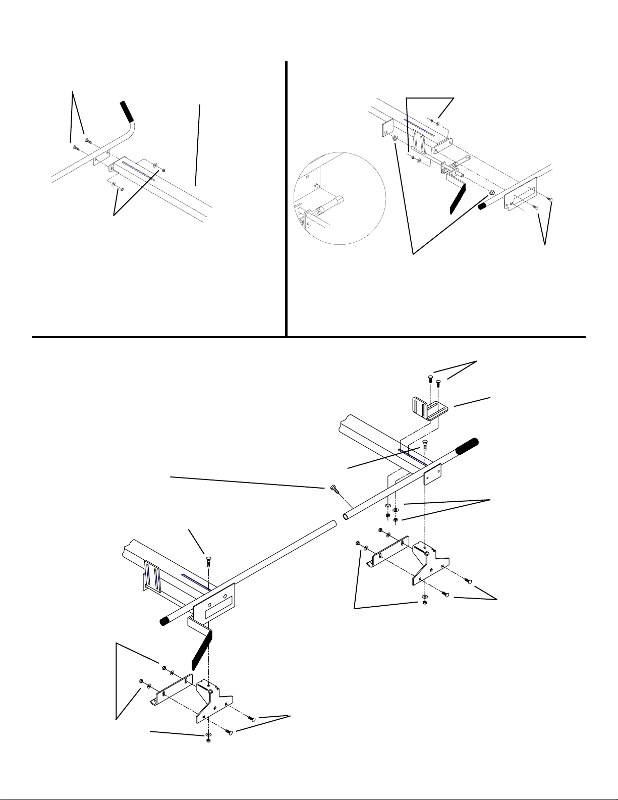
1. Crossmember / Rail Assembly
5/16-18 x 7/8"
Carriage Bolt
5/16" Flat Washer and
5/16-18 Nylon Lock Nut
NOTE: Airfoil on this side
of Front Crossmember
when assembled.
Figure 2. Front Crossmember /
Front Rail Assembly
2. Rack Assembly
NOTE: If installing a Model 225,
assemble it at this time.
Insert the Rear Rail into the
Front Rail and align the holes,
then fasten. Use a drop of
Loctite ® on the 1/4-20 x 1/2"
taptite screws (repeat on opposite side).
5/16-18 x 7/8"
Carriage Bolt
NOTE: For an extended
Chevy Astro, insert the Rear
Rail tube into the Front Rail
tube until the first Rear Rail
tube hole is aligned with the
front rail hole. All other vans
will use the second Rear Rail
tube hole.
5/16-18 x 7/8"
Carriage Bolt
Nylon Bearing
Figure 3. Rear Crossmember /
Rear Rail / Handle Assembly
Loosely fasten
the Stands to the
Crossmembers.
5/16" Flat Washer and
5/16-18 Nylon Lock Nut
5/16-18 x 7/8"
Carriage Bolt
5/16-18 x 1-1/4"
Carriage Bolt
NOTE:
See Figure 11.
Before Assembling
5/16" Flat Washer
and 5/16-18 Nylon
Lock Nut
Loosely fasten the
Mounting Brackets to
the Stands to allow
them to pivot on the
bolts.
5/16" Flat Washer and
5/16-18 Nylon Lock Nut
5/16" Flat Washer and
5/16-18 Nylon Lock Nut
5/16-18 x 7/8"
Carriage Bolt
Figure 4. Side Rail / Stand Assembly
5/16-18 x 7/8"
Carriage Bolt
3
Page 4

3. Adjust then tighten the Stand As-
semblies to the following dimensions:
Chevy Astro/GMC Safari:
Front Crossmember "A" - 1-1/16"
"B" - 56-7/8"
Rear Crossmember "A" - 5-7/8"
"B" - 47-1/4"
Ford Windstar:
Front & Rear Crossmember:
"A" - 7-5/8"
"B" - 43-3/4"
4. With the help of others, lift the rack and
position it on the vehicle. Locate the rear of
the rack on the roof centered side to side
at the dimension shown at right. Mark
through the obrounds in the Mounting
Brackets at the point where the Mounting
Bracket radius meets the roof.
"A"
"B"
Dimension "A" should center the Stands
side to side. Adjust both Stands accordingly if they are not even.
Figure 5. Stand Adjustment
Gap between Door and Roof
4
"A"
Dimension "A" - Stand
placement ahead of rear
edge of roof
Astro/Safari - 3"
Windstar - 1-1/4"
Figure 6. Stand Placement
Page 5

Step 5 for Astro / Safari
5. Drill the marks at the rear of the
roof with a 9/32" drill bit, then apply a
small bead of E-6000 around the
holes. Drill the marks at the front of
the roof with a 13/32" bit. Apply
E-6000 Sealant to the roof around
each hole. Install Blind Fasteners following the installation instructions on
the back page. Once installed, fill the
top of the Blind Fastener holes with E6000 Sealant. Fasten the rack (
ures 7. & 8.)
Mounting
Bracket
w/ Stand
Roof Mounting
Plate
E-6000
Sealant
.
Mounting
Pad
Fig-
CAUTION
Do not apply too much pressure when drilling. Too much
pressure may cause dimples
in the roof around the holes.
Also, there may be a danger of
penetrating the interior head
liner.
1/4-20 x 1-1/2"
Hex Head Bolt
1/4” Lock
Washer
Clamp Bar
Spacer
Roof Mounting
Pad
Roof
E-6000
Sealant
CAUTION
To keep debris out of your
eyes when drilling, always
wear protective eyewear.
Roof
13/32" hole with Blind
Fastener installed
9/32" hole
5/16” Flat Washer
Figure 7. Astro Rear Stand Mounting
Step 5 for
Ford Windstar
5. Drill the marks with a 9/32” drill bit.
Apply E-6000 Sealant to the roof
around each hole. Fasten the Rack to
the roof (
Figure 9.)
.
1/4-20 Nylon Lock Nut
E-6000
Sealant
1/4-20 Nylon Lock Nut
Figure 8. Astro Front Stand Mounting
Roof
5/16” Flat Washer
Figure 9. Windstar Mounting
5
Page 6

6. Adjust the Airfoil to eliminate wind noise by bending it downward to the following dimensions:
Astro/Safari:
15/16" above roof at center
1-11/16" above roof at each end
Windstar:
11/16" above roof at center
1-5/8" above roof at each end
NOTE: These dimensions are guidelines, it may
be necessary to adjust the Airfoil further.
7. Loosely fasten the Top Adj. Clamp
to the Front and Rear Assemblies. To
adjust Clamps, place the ladder on
the rack (Figure 12.) and adjust the
clamps forward or back / up or down
to capture the nearest ladder rung.
Tighten the bolts.
5/16-18 x 7/8
Carriage Bolt
5/16 Flat Washer and
5/16-18 Nylon Lock Nut
This application is used for
standard Extension Ladders.
5/16-18 x 7/8
Carriage Bolt
Figure 10. Rear DS Clamp
5/16 Flat Washer and
5/16-18 Nylon Lock Nut
This application will be needed
for Dead-head ladders and
some Step ladders.
6
Figure 11. Front DS Clamp
Page 7

8. Assemble the Ladder Guides
through the slots of the Crossmembers
and slide up to the ladder. Tighten Fasteners.
CAUTION
To keep debris out of your
eyes when drilling, always
wear protective eyewear.
CAUTION
Load should be approximately centered front to rear. Failure to
do this will cause damage to the vehicle roof. Long loads that
extend out the rear of the vehicle will prevent the rear hatch from
fully opening and cause damage if attempted.
W ARNING
Ladders must be secured per
ANSI standard A142.2-1990
paragraph 8.4.4. Ladder damage will occur from road shock
and vehicle vibration if the ladder is not properly secured to
the ladder rack. Bouncing and
side to side motion of a improperly secured ladder will
cause wear and weaken the
ladder. Using a damaged ladder could lead to a structural
collapse and could result in a
serious injury or death.
5/16" Flat Washer and
5/16"-18 Nylon Lock Nut
5/16-18 x 7/8"
Carriage Bolt
Figure 12. Clamp Adjustment and Ladder Guide Installation
7
Page 8

INSTALLATION PROCEDURE
USING BLIND FASTENERS
CAUTION
Do not apply too much pressure when drilling. Too much
pressure may cause dimples
in the roof around the holes.
Also, there may be a danger of
penetrating the interior head
liner.
Place a drop of oil on the black oxide
bolt before assembling as shown on
right. Place the Blind Fastener in the
hole and use a 1/2” or 7/16” wrench to
tighten black hex bolt until the blind
fastener is fully seated. When setting
black hex bolt, it will start out hard.
As the Blind Fastener “bulbs” out it
will get easier, until it bottoms out or
sets. Make sure the Blind Fastener
and Installation Tool do not turn during
installation.
Black
Oxide
Bolt
Flat
Washer
9/16”
Wrench
Installation
Tool
Blind
Fastener
WEATHER GUARD® PRODUCT
REFINISHING PROCEDURES
All WEATHER GUARD® products are
finished with a polyester powder coating, and it is important to follow these
procedures to get proper adhesion.
As Knaack Manufacturing Co. cannot
control the finishing of the products,
the warranty for WEATHER GUARD®
products on paint is not applicable on
refinished products.
1. Sand the surface to be painted with
180-200 grit sand paper to rough up
the surface. This should be followed
by wet sanding with a 400 grit wet or
dry paper.
2. Wipe down the sanded surface with
ketone based thinner. This removes
the dust and softens the powder coating for better paint adhesion.
3. Wipe sanded area with a tack rag
to remove loose dust and particles
before painting.
NOTE: Do not use a lacquer over
the powdered coating.
- NOTICE -
Any modification or unintended use of this product shall immediately void all manufacturers warranties.
Manufacturer disclaims all liability for injuries to persons or property resulting from any modification to, or
unintended use of this product.
If you have any questions, please give us a call. Call Toll Free 1-800-456-7865
U.S. - 4618083, 5829654, 842268, 1661625, 1663369, 1750034, 2228051; Canada - 1235100, 282725; U.K. - 1400720; N.Z. - 296049
WEATHER GUARD® products are protected by one or more of the following patents or trademarks:
Aus. - 761964
KNAACK MANUFACTURING COMPANY
420 E. TERRA COTTA AVENUE - CRYSTAL LAKE, ILLINOIS, USA 60014
815-459-6020
©2004 Knaack Manufacturing Company
 Loading...