

Page 1
INSTALLATION MANUAL
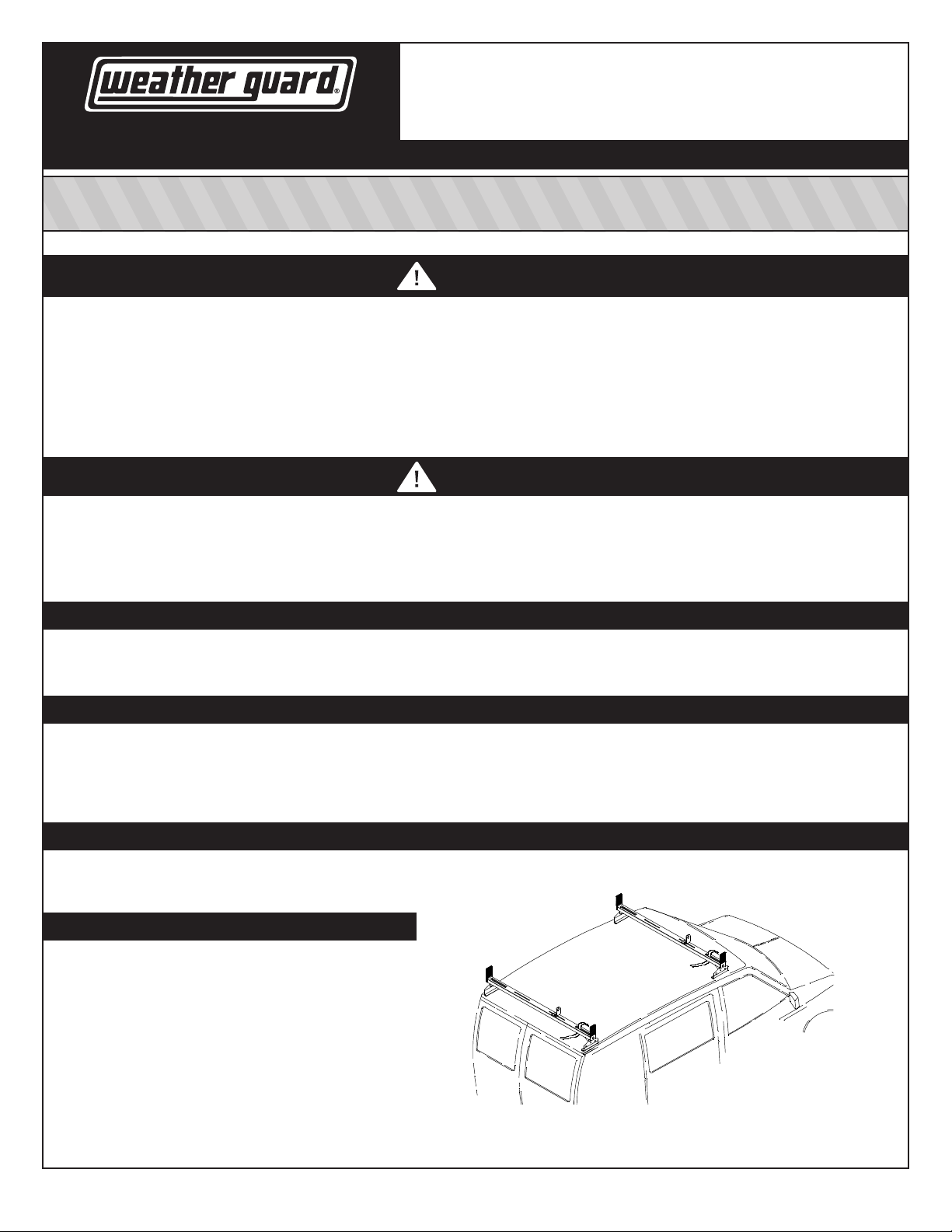
ALL PURPOSE MINI RACK
VAN EQUIPMENT
FOR THE WAY YOU WORK™
ATTENTION: PLEASE READ AND UNDERSTAND ALL INSTRUCTIONS AND WARNINGS
BEFORE ASSEMBLING, INSTALLING OR USING THIS PRODUCT.
WARNING
This product is only intended for, and only safe for transporting ladders, lumber, pipe and other similar materials. It is the responsibility of the user to
secure these materials to the rack before transporting. These instructions are to be followed using the parts and fasteners supplied for proper installation.
Any modications made to this product, or use of this product for any other purpose than its intended use, could create a hazardous condition that
can cause serious personal injury or property damage.
Ladder must be secured per ANSI standard A1422-1990 paragraph 8.4.4. Ladder damage will occur from road shock and vehicle vibration if the ladder
is not properly secured to the ladder rack. Bouncing and side to side motion of an improperly secured ladder will cause wear and weaken the ladder.
Using a damaged ladder could lead to a structural collapse and could result in a serious injury or death.
CAUTION
Load should be approximately centered front to rear on all vehicles. Failure to do this will cause damage to the vehicle roof. Long loads that extend
out the rear of the vehicle will prevent the rear hatch from fully opening and cause damage if attempted.
Do not apply too much pressure when drilling. Too much pressure may cause dimples in the roof around the holes. Also, there may be a danger of
penetrating the interior head liner. To keep debris out of your eyes when drilling, always wear protective eyewear.
Model 218-3 • 222-3
WWW.WEATHERGUARD.COM
– NOTICE –
Any modication or unintended use of this product shall immediately void all manufacturers warranties. Manufacturer disclaims all liability for injuries
to persons or property resulting from any modication to, or unintended use of this product.
NOTE
We have found varying tolerances between the top of the doors and the rain gutters on the 1992 to present full-size vans. Before placing van rack
on vehicle, check the door clearance with the bottom clamp, by holding it to the underside of the rain gutter and slowly opening the door. If the door
hits, you will have to move the clamp to where more clearance is available. Some cases may require moving the clamps rearward of the driver and
passenger side doors.
INSTALLATION TIME
Approximate installation time: Model 218-3: 60 minutes per unit (1 hour); 222-3: 24 minutes per unit (0.4 hour) depending on van equipment
installation experience.
TOOLS REQUIRED
• Electric Drill
• 9/32", 13/32" Drill Bit
• Ratchet Wrench
• 7/16" Open or Box Wrench
• 7/16" Socket
• Ruler
• Straight Board
• 1/2" Socket (deep well preferred)
• 9/16" Open or Box End Wrench
The distinctive, trademarked RED TIPS are your assurance
of WEATHER GUARD® Equipment Quality.
*24-0161*
1
Part No. 24-0161 Rev B 11/11 (5026)
Page 2
BOLT KITS
Bolt Kit # 32-0120 and 32-0122 are provided wth 218-3 and 222-3. Check the bolt kit to be sure the following parts are included:
Model 218-3 222-3
DESCRIPTION
Bolt Kit 32-0120 32-0122
Quantity
1 1
4 4
1 1
16 8
32 16
8 4
4 4
1 1
8 4
16 8
Installation Tool
1/4-20 Blind Fastener
1/4-20 x 2-1/4" Blk. Ox. Bolt
5/16-18 Nylon Lock Nut
5/16" Flat Washer
1/4-20 Nylon Lock Nut
1/4" Lock Washer
1/4" Flat Washer (yellow)
1/4-20 x 3/4" Hex Hd. Bolt
5/16-18 x 1" Carriage Bolt
1 1
8 4
2 0
218-3 DESCRIPTION
4 Mounting Bracket
4 Stand
1 Crossmember w/ Airfoil
1 Crossmember w/o Airfoil
4 Clamp Bar
4 Mounting Pad
2 Roof Mounting Plate
2 Ladder Guide
2 Ladder Straps
1 oz. Tube E-6000 Sealant
Spacer - 1/8" thick
Roof Mounting Pad
PARTS LIST
222-3 DESCRIPTION
2 Stand
1 Crossmember w/o Airfoil
2 Center Mounting Bracket
2 Clamp Bar
2 Mounting Pad
1 Ladder Guide
2
Page 3
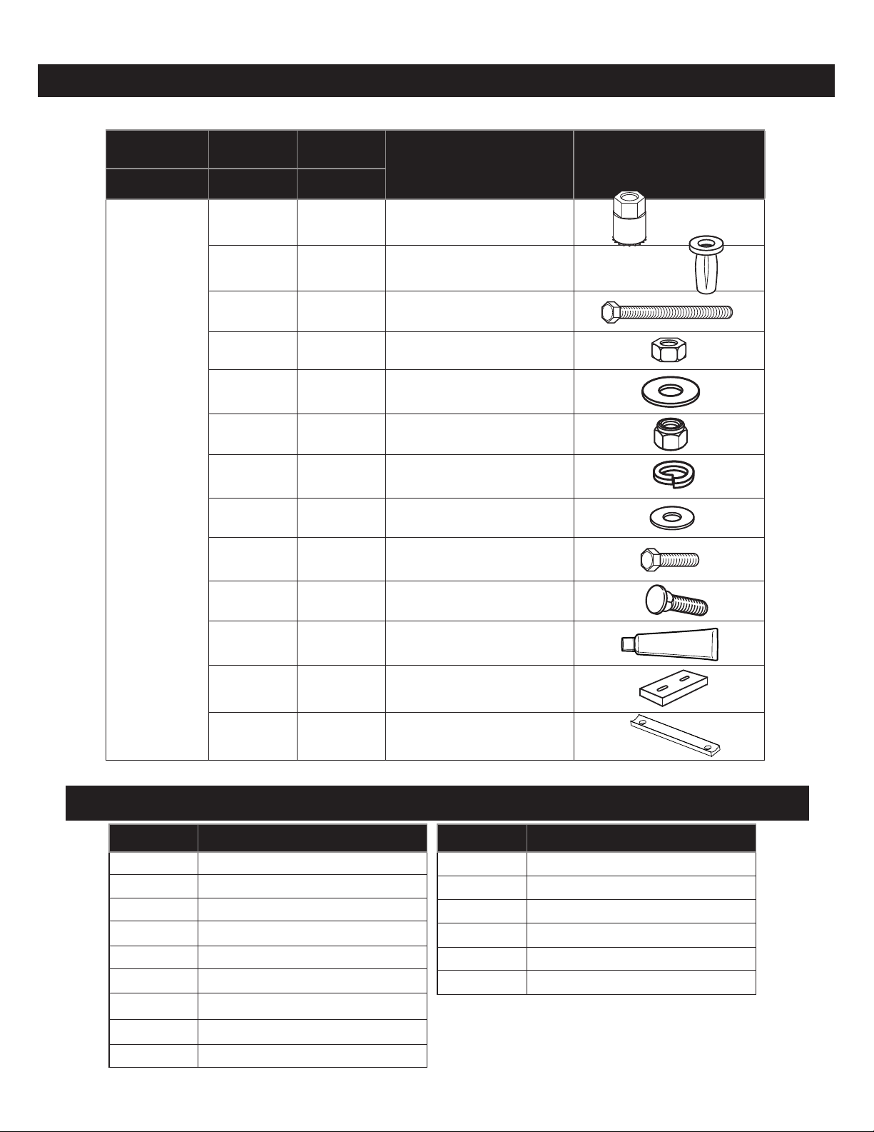
Clamp Bar
Mounting Pad
Roof Mounting
Plate
Ladder Guide
Mounting Bracket
Crossmember
(w/o Airfoil)
Crossmember
(w/ Airfoil)
Ladder
Straps
222-3 Center
Mounting Bracket
222-3 Stand
218-3 Stand
Figure 1. Parts Identification
ASSEMBLY INSTRUCTIONS
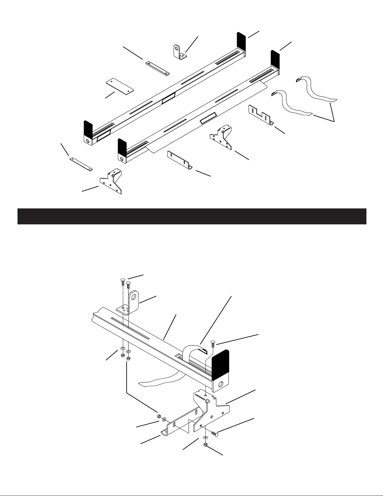
STEP 1. Fasten the Mounting Brackets to the Stands, just loose enough to pivot on the bolts (see Figure 1.). Loosely
fasten the Stands to the Crossmembers. Attach the Ladder Guide through the slot in crossmember as shown, Ladder
Guide can also be installed on either the passenger or driver side. The Ladder Guide can be adjusted in the slot to
accommodate your ladders width. Thread Ladder Strap through opening in slot.
5/16-18 x 7/8"
Carriage Bolt
Ladder Guide
Crossmember
5/16" Flat
Washer
Ladder
Strap
5/16-18 x 7/8"
Carriage Bolt
5/16-18 Nylon
Lock Nut
5/16" Flat Washer
Mounting
Bracket
5/16" Flat
Washer
Figure 2. Stand Assembly
3
Stand
5/16-18 x 7/8"
Carriage Bolt
5/16-18 Nylon Lock Nut
Page 4

ASSEMBLY INSTRUCTIONS
STEP 2. Adjust then tighten the Stand Assemblies to the following dimensions:
Chevy Astro/GMC Safari:
Front Crossmember "A" - 1-1/16"
"B" - 56-7/8"
Rear Crossmember "A" - 5-7/8"
"B" - 47-1/4"
Ford Windstar:
Front & Rear Crossmember:
"A" - 7-5/8"
"B" - 43-3/4"
STEP 3. Locate the Rear Crossmember Assembly on the roof centered side to side at the dimension shown at right.
Mark through the obrounds in the Mounting Brackets at the point where the Mounting Bracket radius meets the roof.
"A"
"B"
Dimension "A" should center the Stands
side to side. Adjust both Stands accordingly if they are not even.
Figure 3. Stand Adjustment
Dimension "A" - Stand placement
ahead of rear edge of roof
"A"
Astro/Safari - 3"
Windstar - 1-1/4"
Figure 4. Stand Placement
STEP 4. Locate the Front Crossmember Assembly centered side to side from back edge of Rear Stand to back edge
of Front Stand at the dimensions shown at right. Again, mark through the obrounds in the Mounting Brackets.
Airfoil to face
forward
Standard length vans - 74-3/8"
Extended length vans - 86-3/8"
Figure 5. Stand / Crossmember Spacing
4
Page 5
STEP 5. For Astro/Safari
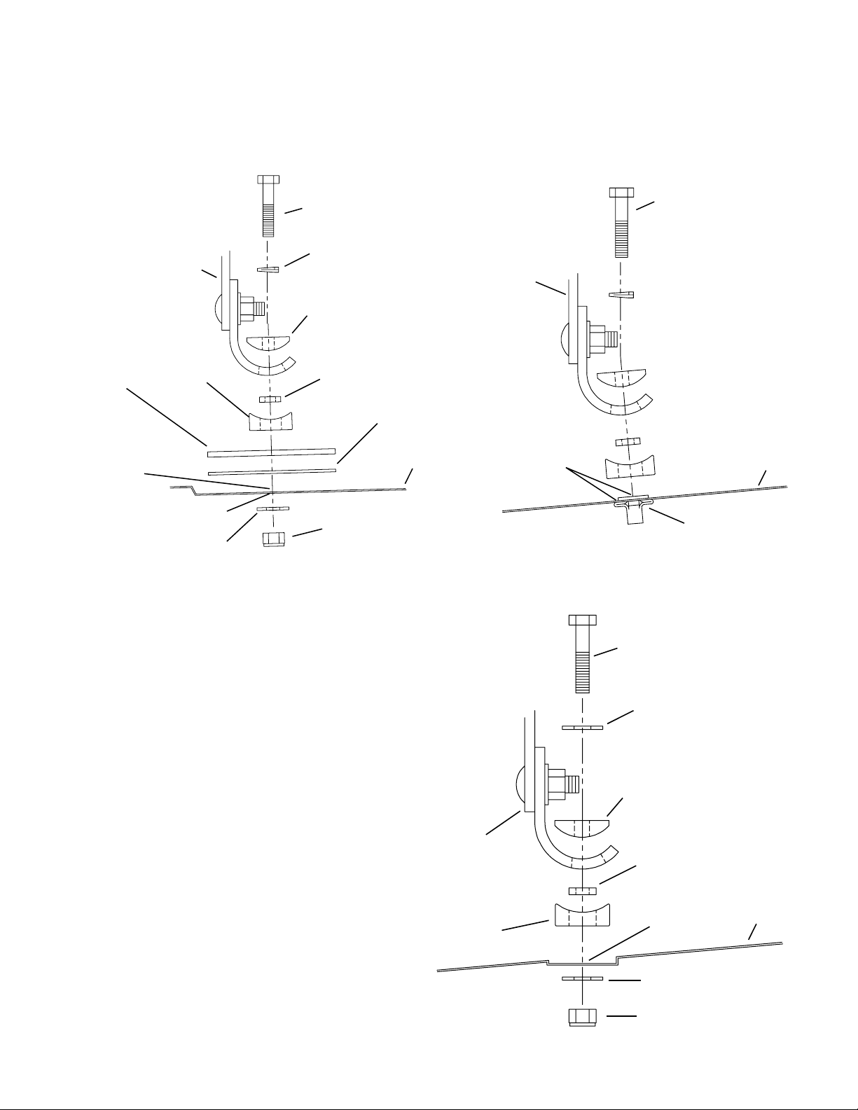
Drill the marks at the rear of the roof with a 9/32" drill bit, then apply a small bead of E-6000 around the holes. Drill
the marks at the front of the roof with a 13/32" bit. Apply E- 6000 Sealant to the roof around each hole. Install Blind
Fastener following the installation instructions on the back page. Once installed, ll the top of the Blind Fastener holes
with E-6000 Sealant. Fasten the rack as shown in Figures 6. & 7.
Roof Mounting
Plate
E-6000
Sealant
Mounting
Bracket
w/ Stand
Mounting
Pad
9/32" hole
5/16” Flat Washer
Figure 6. Astro Rear Stand Mounting
1/4-20 x 1-1/2"
Hex Head Bolt
1/4” Lock
Washer
Clamp Bar
Spacer
Roof Mounting
Pad
1/4-20 Nylon Lock Nut
Roof
Mounting
Bracket
w/ Stand
E-6000
Sealant
1/4-20 x 1-1/2"
Hex Head Bolt
Roof
13/32" hole with Blind
Fastener installed
Figure 7. Astro Front Stand Mounting
STEP 5. For Astro/Safari
Drill the marks at the rear of the roof with a 9/32" drill bit,
then apply a small bead of E-6000 around the holes. Drill
the marks at the front of the roof with a 13/32" bit. Apply
E- 6000 Sealant to the roof around each hole. Install Blind
Fastener following the installation instructions on the back
page. Once installed, ll the top of the Blind Fastener
holes with E-6000 Sealant. Fasten the rack as shown in
Figures 6. & 7.
Mounting
Bracket
w/ Stand
Mounting
Pad
1/4-20 x 1-1/2"
Hex Head Bolt
5/16” Flat Washer
Clamp Bar
Spacer
E-6000
Sealant
5/16” Flat Washer
1/4-20 Nylon Lock Nut
Roof
Figure 8. Windstar Mounting
5
Page 6

STEP 6. Adjust the Airfoil to eliminate wind noise by bending it downward to the following dimensions:
Fasten the
Mounting Bracket
to the top two holes
Astro/Safari: Windstar:
15/16" above roof at center 11/16" above roof at center
1-11/16" above roof at each end 1-5/8" above roof at each end
NOTE: These dimensions are guidelines, it may be necessary to adjust the Airfoil further.
Model 222-3 ASSEMBLY INSTALLATION
Loosely fasten the Mounting Brackets to the Stands, then the Stands to the Crossmember. Adjust the Stands as in
Step 2. to the Front Crossmember dimensions. Center the 222-3 on the roof evenly between the 218-3 Stands, as
well as centered side to side. Install the Rack the same as the Front Crossmember. Once installed, place a straight
board on the 218-3. Adjust the 222-3 Crossmember up to the board, keeping the Crossmember level, then tighten the
Stand to Mounting Bracket bolts.
Fasten the
Mounting Bracket
to the top two holes
INSTALLATION PROCEDURE USING BLIND FASTENERS
Place a drop of oil on the black oxide bolt before assembling as shown on right. Place the Blind Fastener in the hole
and use a 1/2” or 7/16” wrench to tighten black hex bolt until the blind fastener is fully seated. When setting black hex
bolt, it will start out hard. As the Blind Fastener “bulbs” out it will get easier, until it bottoms out or sets. Make sure the
Blind Fastener and Installation Tool do not turn during installation.
7/16
Black
Oxide
Bolt
Flat
Washer
7/16”
Wrench
Installation
Tool
Your Installation Tool
may look like this.
Blind
Fastener
6
Page 7

KNAACK LLC LIMITED LIFETIME WARRANTY FOR WEATHER GUARD® PRODUCTS
WEATHER GUARD® Products — Limited Lifetime Warranty
(Purchased on or after 1/1/2009)
Knaack LLC (the “Manufacturer”) warrants to the original purchaser only that WEATHER GUARD® Truck and Van Products
(the “WEATHER GUARD® Product”) will be free from defects in material and workmanship from the date of purchase and
continuing for the expected lifetime of the WEATHER GUARD® Product. A copy of the original sales receipt must be supplied
to the Manufacturer at the time a warranty claim is made. This warranty terminates if the original purchaser transfers the
WEATHER GUARD® Product to any other person.
What is Covered
All WEATHER GUARD® Products identified above that are purchased on or after January 1, 2009.
What We Will Do to Correct Problems
Subject to the limitations and exclusions described in this limited warranty, the Manufacturer will remedy defects in materials
or workmanship by providing one of the following remedies at its option and without charge to the original purchaser for parts
or labor: (a) repairing the defective portion of the WEATHER GUARD® Product or (b) replacing the entire WEATHER GUARD®
Product. In addition, the manufacturer may elect at its option, not to repair or replace the WEATHER GUARD® Product, but
rather issue to the original purchaser a refund equal to the purchase price paid for the WEATHER GUARD® Product or a credit
to be used toward the purchase of new WEATHER GUARD® Product.
What is Not Covered
This limited warranty expressly excludes:
• Defects caused by normal wear and tear, cosmetic rust, scratches, accidents, unlawful vehicle operation, or
modification to the product, or any types or repair of a WEATHER GUARD® Product other than those authorized or
provided by the Manufacturer.
• Defects resulting from conditions beyond the Manufacturer’s control including, but not limited to misuse, overloading,
or failure to assemble, mount or use the WEATHER GUARD® Product in accordance with the Manufacturer’s written
instructions or guidelines included with the WEATHER GUARD® Product or made available to the original purchaser.
• Damage to the contents of the box or vehicle.
• TO THE EXTENT PERMITTED BY LAW, IN NO EVENT SHALL THE MANUFACTURER BE LIABLE FOR ANY
INCIDENTAL, SPECIAL, INDIRECT, OR CONSEQUENTIAL DAMAGES, INCLUDING ANY ECONOMIC LOSS,
WHETHER RESULTING FROM NONPERFORMANCE, USE, MISUSE OR INABILITY TO USE THE WEATHER
GUARD® PRODUCT OR THE MANUFACTURER’S NEGLIGENCE.
No Other Express Warranty Applies
This Limited Lifetime Warranty is the sole and exclusive warranty for WEATHER GUARD® products. No employee, agent,
dealer, or other person is authorized to alter this warranty or make any other warranty on behalf of Knaack LLC.
Notification Procedures
If the WEATHER GUARD® Product does not conform with the terms of this limited warranty, the original owner must promptly
notify the Manufacturer in writing upon discovery of the nonconformity. In order to receive the remedies under this limited
warranty, the warranty claim must describe the nature of the nonconformity, and a copy of the original sales receipt, invoice,
bill or other proof of purchase must accompany the claim. Repairs or modifications made to the WEATHER GUARD® Product
by other than the Manufacturer or its authorized agent will nullify this limited warranty. Coverage under this limited warranty is
conditioned at all times upon the owner’s compliance with these required notification and repair procedures. Warranty claims
must include reciprocal contact information and may be made via certified mail to:
Knaack LLC
ATTN: Warranty Claims
420 E. Terra Cotta Avenue
Crystal Lake, IL 60014
*24-0161*
If you have any questions, please call toll free at 1-800-456-7865.
©2011 Knaack LLC
7
Part No. 24-0161 Rev B 11/11 (5026)
 Loading...