

Page 1
TRUCK STORAGE SOLUTIONS
SECURING YOUR REPUTATION
ATTENTION: PLEASE READ AND UNDERSTAND ALL INSTRUCTIONS AND WARNINGS
BEFORE ASSEMBLING, INSTALLING OR USING THIS PRODUCT.
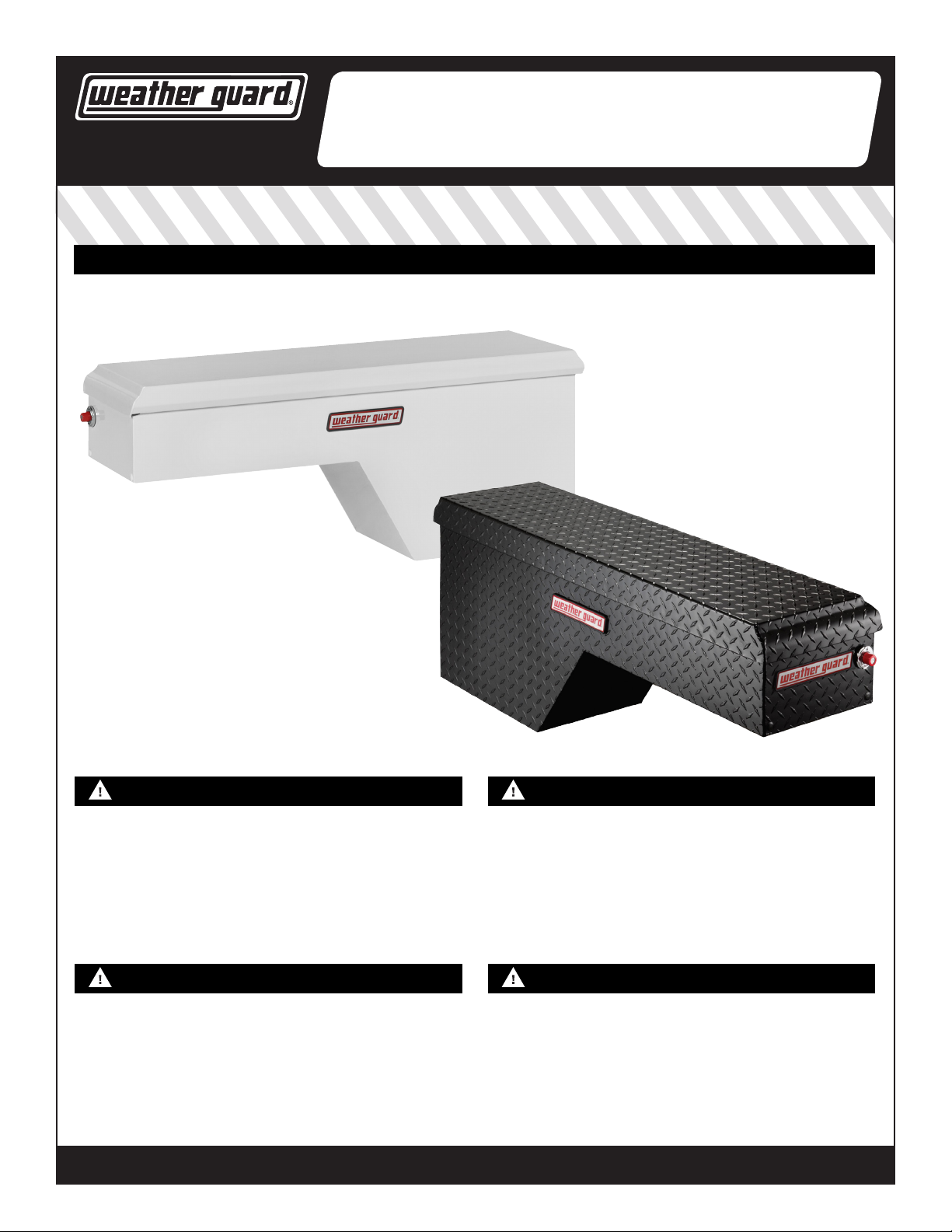
INSTALLATION MANUAL
STEEL & ALUMINUM SIDE BOX WITH
ALUMINUM & STEEL PORK CHOP BOX
®
PACK RAT® DRAWER UNITS
MODELS
160-X-01, 161-X-01, 162-X-01, 163-X-01, 170-X-01, 171-X-01, 172-X-01, 173-X-01
Note: X represents the color code for your model: 0 = Clear | 3 = White | 5 = Black
NOTICE WARNING
Use specic aluminum upt components when installing WEATHER GUARD®
products to aluminum truck beds. Follow additional instructions if mounting
to an aluminum truck bed. There may be left over components depending on
upt.
Any modication or unintended use of this product shall immediately void all
manufacturers warranties. Manufacturer disclaims all liability for injuries to
persons or property resulting from any modication to, or unintended use of
this product.
DANGER CAUTION
Danger of explosion. Do not use this product for storing or transporting
ammables, explosives, hazardous materials, or hazardous waste, such
as containers of gasoline, solvents, gun powder, dynamite, propane tanks,
acetylene tanks and cutting torches. This product is only intended and safe
for use in storing and transporting small tools, equipment and other similar
materials. Any modications made to, or unintended use of this product, could
create a hazardous condition that can cause death, serious personal injury or
property damage.
©2015 KNAACK LLC
Prior to drilling, so as not to cut or puncture fuel tanks, fuel lines, electric
wires, etc., check under vehicle for locations. All oor mounting bolts near
the gas tank area should be installed from the underside of the vehicle, to
guard against the gas tank being punctured in the event of a collision. This
would mean not using Blind Fastener in this area. Holes drilled in this area
should be 3/8".
Before marking the leg mounting holes, check inside the box for location of
gas spring housing and components that may obstruct safe drilling. To keep
debris out of your eyes when checking the underside of the vehicle, or when
drilling, always wear protective eyewear.
WEATHERGUARD.COM
WEATHERGUARD.COM
Part No. 24-0176 REV. E ECN 5583 05/15
Page 2
TOOLS REQUIRED
• Electric Drill
• Drill Bits - 3/16", 3/8", 1/2"
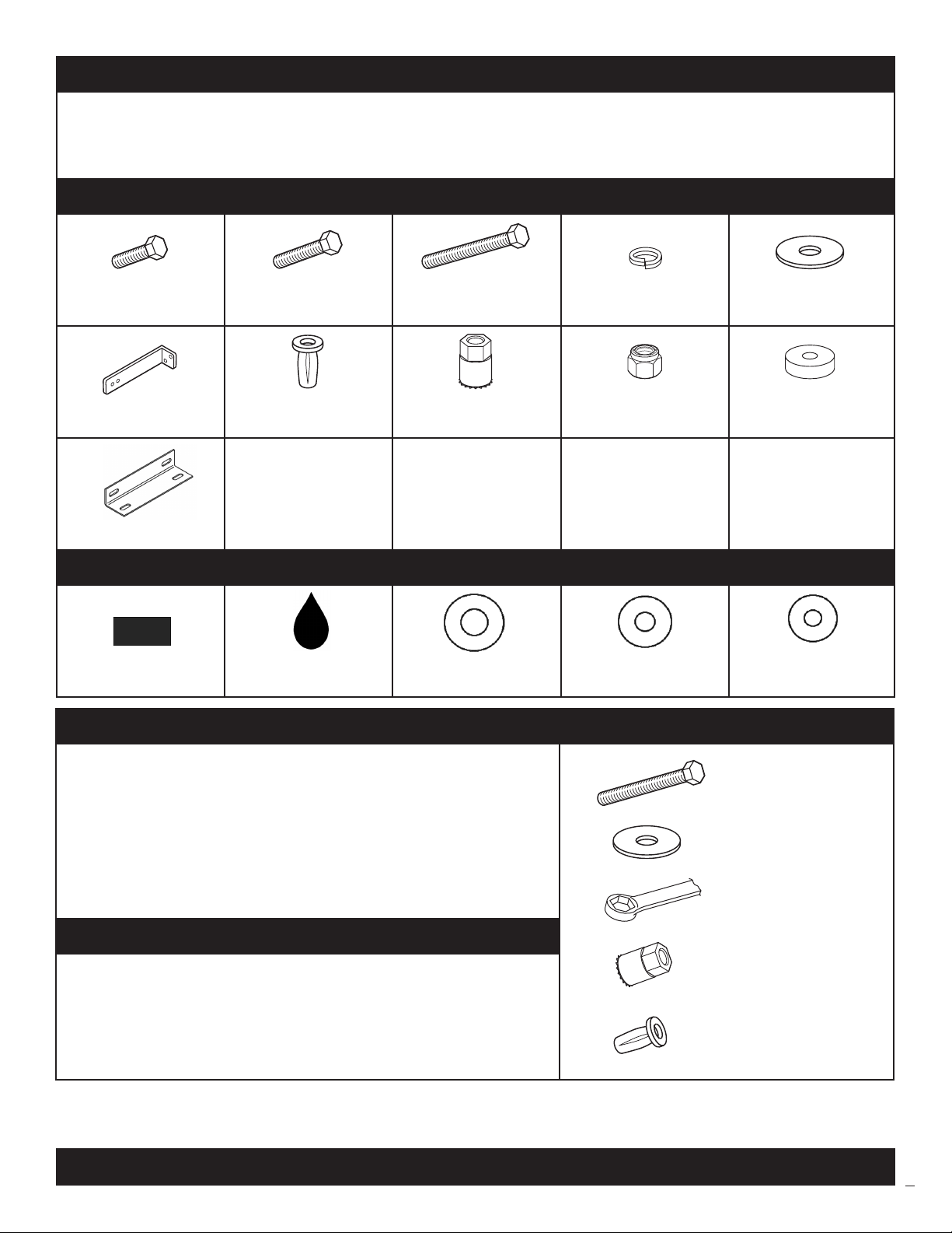
PARTS LIST
(6) 5/16-18 x 1"
Hex Head Bolt
(2) Mounting Angle
(1) Floor Mounting Angle
• Open or Box End Wrenches - (2) 1/2", 9/16"
• Hammer
• Oil/Grease
(3) 5/16-18 x 1-1/4"
Hex Head Bolt
(3) 5/16-18
Blind Fastener
(1) 5/16-18 x 2-1/4"
Black Oxide Bolt
(1)
Installation Tool
(3) 5/16"
Lock Washer
(6) 5/16-18
Nylon Lock Nut
• Center Punch
• Carpenter’s Square
• Pencil/Marker
(14) 5/16"
Flat Washer
(2)
Floor Mounting Spacer
ALUMINUM BED UPFIT KIT PARTS LIST - 32-0243
(4)
Vinyl Tape
(1)
Zinc Rich Primer
(8) 1/2" x 1"
Plastic Washer
BLIND FASTENER INSTALLATION
Place a drop of oil on black oxide bolt for lubrication before assembling.
Place the Blind Fastener in the hole and use 1/2" or 7/16" wrench to
tighten black oxide bolt until fastener is fully seated (it will start out hard
and get easier as fastener “bulbs” out).
Make sure the Blind Fastener and Installation Tool do not turn during
installation.
ALUMINUM TRUCK BED INSTALLATION
Coat drilled holes with Zinc Rich Primer. Insert Blind Fastener through one
1/2" x 1" plastic washer. Insert Blind Fastener into drilled hole. Place
second 1/2" x 1" plastic washer through the bottom of the Blind Fastener.
Continue following installation instructions above to install Blind Fasteners.
(4) 11/32" x 7/8"
Plastic Washer
(8) 5/16" x 3/4"
Plastic Washer
Black Oxide Bolt
Flat Washer
9/16" Wrench
Installation Tool
Blind Fastener
©2015 KNAACK LLC
2
Page 3

INSTALLATION INSTRUCTIONS
Note:
• If your truck bed is constructed of aluminum, use zinc rich primer to coat drilled holes.
• If your pickup is tted with a plastic drop-in bed liner, it may need to be drilled, trimmed, or cut for proper installation of truck box.
• Truck box cover may not properly latch until box is fully bolted to truck bed.
• Periodically check tightness of mounting bolts to ensure proper attachment.
• Use touch-up paint on any drilled holes to prevent oxidation.
• Install boxes with vehicle parked on level ground.
STEP 1
Locate Box in Truck Bed
Note:
Place box into position with cover open. Support box
as required during installation. Verify tailgate closes
with mounting angle in position. Bottom of box should
be at on the oor. Side of box (not cover) should be
approximately 1" from bed rail.
• Fasten box and leg mounting feet directly to
bed oor, not bed liners or mats.
ALUMINUM TRUCK BED INSTALLATION:
Use vinyl tape as a barrier between the mounting clamp and
truck bed. Follow same instructions if mounting with a “J” bolt.
5/16-18
Blind
Fastener
STEP 2
Attach End Mounting Angle
Note:
• This step may be omitted if you are able to use
the alternate method in Step 3A. Make sure
there is enough hole depth before installing
the blind fastener.
Bed Lip
Support Here
5/16"
Lock Washer
5/16"-18 x 1-1/4"
Hex Head Bolt
5/16"-18 x 3/4"
Nylon Lock Nut
©2015 KNAACK LLC
5/16" Flat Washer
Mounting Angle
5/16"-18 x 3/4"
Hex Head Bolt
Place mounting angle against end of box with foot
touching stake pocket (or inner wall of truck bed). Mark
one hole on the box and one hole on the truck. Center
punch the holes to be drilled. Drill truck box and stake
pocket (or inner wall) with 3/16" drill bit. Re-drill hole in
truck box with 3/8" drill bit. Re-drill hole in stake pocket
(or inner wall) with 1/2" drill bit. Install Blind Fastener in
stake pocket (or inner wall). Install mounting angle.
ALUMINUM TRUCK BED INSTALLATION:
Follow additional instructions if mounting to an aluminum truck
bed as explained in the Blind Fastener Installation on page 2.
3
Page 4

STEP 3A
Attach Lower Mounting Angle
Note:
• Install bolts from underside when fastening
mounting angle to wheel well.
5/16"-18 x 1-1/4"
Hex Head Bolt
• This step may be omitted if you are able to
use the alternate method.
Place mounting angle under box and against wheel
well. Mark one hole on bottom of box and both holes
on wheel well. Center punch the holes to be drilled.
Drill truck box and wheel well with 3/16" drill bit.
Install mounting bracket.
ALUMINUM TRUCK BED INSTALLATION:
Follow additional instructions if mounting to an aluminum truck
bed as explained in the Blind Fastener Installation on page 2.
5/16"
Flat Washer
5/16"-18 x 1"
Hex Head Bolt
ALUMINUM TRUCK BED INSTALLATION:
Follow additional instructions if mounting to an aluminum truck
bed as explained in the Blind Fastener Installation on page 2.
5/16"
Flat Washer
5/16-18 x 3/4"
Nylon Lock Nut
5/16"-18
Nylon Lock Nut
STEP 3B
Mounting Angle
Alternate Mounting Method
Note:
• Install bolts from underside when
fastening Mounting Angle to wheel
well.
Use if truck conguration allows box to rest
directly on wheel well. Mark, center punch
and drill 3/16" hole in bottom of box and top
of wheel well shown in the gure to the right.
Re-drill holes with 3/8" drill bit. Install bolt as
shown in gure to the left.
STEP 4
Attach Floor Mounting Angle
Note:
Place oor mounting angle on oor,
centered behind the box. Mark, center
punch and drill all four holes with 3/16"
drill bit. Re-drill holes in box with a 3/8"
drill bit. Re-drill holes in truck bed with
1/2" drill bit. Install Blind Fasteners in
truck bed. Install oor mounting angle as
shown in gure to the right.
©2015 KNAACK LLC
• If holes in Floor Mounting Angle are not
positioned above rib, use Floor Mounting
Spacers provided.
5/16"-18 x 3/4"
Hex Head Bolt
5/16"
Flat Washer
Floor
Mounting
Angle
5/16"
Lock Washer
(when needed)
Tailgate End
5/16"-18 x 1-1/4"
Hex Head Bolt
5/16"-18
Nylon Lock Nut
5/16-18 Blind FastenerFloor Mounting Spacer
4
Page 5

FEATURE OPERATION
Lock System
The WEATHER GUARD® Extreme Protection™
Lock is designed to provide maximum
security, while providing ease of use and
years of reliable service. When in the locked
mode, the button remains retracted in a
tamper-resistant position. When the button is
Lock
Turn the key counterclockwise to
the locked position as indicated
on the lock bezel. When the
button is now pressed, it will
stay in the retracted or tamperresistant position until unlocked.
Unlock
Turn the key clockwise to the
unlocked position as indicated
on the lock bezel. Button will
pop out and is now ready
to release the latches when
pressed.
pressed in the unlock mode, the latches are
activated and the cover opens.
Latch System
The WEATHER GUARD® Latch System utilizes automotive grade latches in conjunction with high strength latch strikers to ensure maximum
security. The WEATHER GUARD® Latch System is designed to open with a single touch of the button, and close securely. Expect years of reliable
service from the WEATHER GUARD® Latch System with only minimal maintenance: Lubricate latch pivot points bi-annually with white grease. If
latch strikers are accidentally knocked out of alignment, simply use a mallet to re-align.
SERVICE PARTS
# PART # DESCRIPTION FITS MODEL #
1 7095 Gas Spring 170-X-01, 171-X-01, 172-X-01, 173-X-01
1 7096 Gas Spring 162-X-01, 163-X-01
Lock & Key Set
2 7748-XX
3 7750-XX
4 7731
5 7106
6 7730
7 7735-X Mounting Kit All Pork Chop
8 7746
9 7788-X Cover 170-X-01
9 7789-X Cover 171-X-01
9 7790-X Cover 172-X-01
9 7795-X Cover 173-X-01
9 7726-X Cover 160-X-01
9 7827-X Cover 161-X-01
9 7828-X Cover 162-X-01
9 7832-X Cover 163-X-01
10 7738 Latch Rod Kit (not shown) 160-X-01, 162-X-01, 170-X-01, 172-X-01
10 7739 Latch Rod Kit (not shown) 161-X-01, 163-X-01, 171-X-01, 173-X-01
(XX = key code)
(1 lock, 2 keys, retainer clip)
Key Replacement
(XX = key code ) (2 keys)
Latch & Striker Kit (1 latch,
1 striker, mounting hardware)
Striker Kit (1 striker and
mounting hardware)
Weather Strip Kit
(various styles for one box)
Nameplate Kit (3 stickers, 2
side bezels, 1 back bezel)
All Pork Chop
All Pork Chop
All Pork Chop
All Pork Chop
All Pork Chop
All Pork Chop
2
7
3
6
5
9
8
4
1
Note: X represents the color code for your model:
0 = Clear | 3 = White | 5 = Black
©2015 KNAACK LLC
5
Page 6

KNAACK LLC LIMITED LIFETIME WARRANTY FOR WEATHER GUARD® PRODUCTS
WEATHER GUARD® Products — Limited Lifetime Warranty
(Purchased on or after 1/1/2009)
KNAACK LLC (the “Manufacturer”) warrants to the original purchaser only that WEATHER GUARD® Truck and Van Products (the “WEATHER GUARD®
Product”) will be free from defects in material and workmanship from the date of purchase and continuing for the expected lifetime of the WEATHER
GUARD® Product. A copy of the original sales receipt must be supplied to the Manufacturer at the time a warranty claim is made. This warranty terminates
if the original purchaser transfers the WEATHER GUARD® Product to any other person.
What is Covered
All WEATHER GUARD® Products identied above that are purchased on or after January 1, 2009.
What We Will Do To Correct Problems
Subject to the limitations and exclusions described in this limited warranty, the Manufacturer will remedy defects in materials or workmanship by
providing one of the following remedies at its option and without charge to the original purchaser for parts or labor: (a) repairing the defective portion of
the WEATHER GUARD® Product or (b) replacing the entire WEATHER GUARD® Product. In addition, the Manufacturer may elect at its option, not to repair
or replace the WEATHER GUARD® Product, but rather issue to the original purchaser a refund equal to the purchase price paid for the WEATHER GUARD®
Product or a credit to be used toward the purchase of a new WEATHER GUARD® Product.
What is Not Covered
This limited warranty expressly excludes:
• Defects caused by normal wear and tear, cosmetic rust, scratches, accidents, unlawful vehicle operation, or modication to the product, or any
types or repair of a WEATHER GUARD® Product other than those authorized or provided by the Manufacturer.
• Defects resulting from conditions beyond the Manufacturer’s control including, but not limited to misuse, overloading, or failure to assemble, mount
or use the WEATHER GUARD® Product in accordance with the Manufacturer’s written instructions or guidelines included with the WEATHER GUARD®
Product or made available to the original purchaser.
• Damage to the contents of the box or vehicle.
• TO THE EXTENT PERMITTED BY LAW, IN NO EVENT SHALL THE MANUFACTURER BE LIABLE FOR ANY INCIDENTAL, SPECIAL, INDIRECT, OR CONSEQUENTIAL
DAMAGES, INCLUDING ANY ECONOMIC LOSS, WHETHER RESULTING FROM NONPERFORMANCE, USE, MISUSE OR INABILITY TO USE THE WEATHER
GUARD® PRODUCT OR THE MANUFACTURER’S NEGLIGENCE.
No Other Express Warranty Applies
This Limited Lifetime Warranty is the sole and exclusive warranty for WEATHER GUARD® Products. No employee, agent, dealer, or other person is
authorized to alter this warranty or make any other warranty on behalf of KNAACK LLC.
Notication Procedures
If the WEATHER GUARD® Product does not conform with the terms of this limited warranty, the original owner must promptly notify the Manufacturer in
writing upon discovery of the nonconformity. In order to receive the remedies under this limited warranty, the warranty claim must describe the nature of
the nonconformity, and a copy of the original sales receipt, invoice, bill or other proof of purchase must accompany the claim. Repairs or modications
made to the WEATHER GUARD® Product by other than the Manufacturer or its authorized agent will nullify this limited warranty. Coverage under this
limited warranty is conditioned at all times upon the owner’s compliance with these required notication and repair procedures. Warranty claims must
include reciprocal contact information and may be made via certied mail to:
KNAACK LLC
ATTN: Warranty Claims
420 E. Terra Cotta Avenue
Crystal Lake, IL 60014
If you have any questions,
please call toll free at 1-800-456-7865
WEATHER GUARD® Products are protected by one or more of the following patents:
U.S. - 5145087, 5308126, 4509787, 4573731, 4618083, D-346355, D-346994, D-353574; Canada - 1218968, 1224230, 1235100 and; U.K. - 2233036. Other patents pending.
©2015 KNAACK LLC
WEATHERGUARD.COM
WEATHERGUARD.COM
Part No. 24-0176 REV. E ECN 5583 05/15
6
 Loading...