

Page 1
TRUCK STORAGE SOLUTIONS
SECURING YOUR REPUTATION
ATTENTION: PLEASE READ AND UNDERSTAND ALL INSTRUCTIONS AND WARNINGS
BEFORE ASSEMBLING, INSTALLING OR USING THIS PRODUCT.
INSTALLATION MANUAL
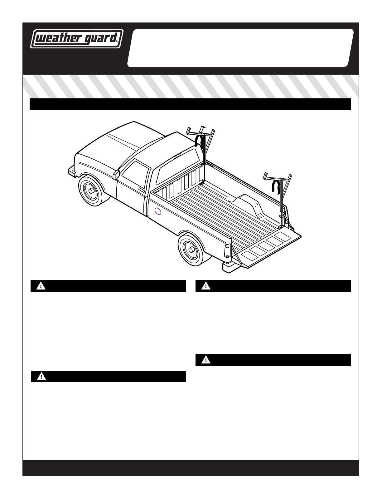
STEEL & ALUMINUM SIDE BOX WITH
WEEKENDER® STEEL LADDER RACK
®
PACK RAT® DRAWER UNITS
MODELS
1450, 1475
1475 shown
NOTICE
Use specic aluminum upt components when installing WEATHER GUARD®
products to aluminum truck beds. Follow additional instructions if mounting
to an aluminum truck bed. There may be left over components depending on
upt.
Any modication or unintended use of this product shall immediately void
all manufacturers warranties. Manufacturer disclaims all liability for injuries
to persons or property resulting from any modication to, or unintended use
of this product. Do not seal uprights to the leg socket seams. It is strongly
suggested that the upright assemblies be removed and stored when not in
use. Warranty will be void if sealant is not properly applied to all seams.
CAUTION
Before marking the leg mounting holes, check inside the box for location of gas
spring housing and components that may obstruct safe drilling. To keep debris
out of your eyes when checking the underside of the vehicle, or when drilling,
always wear protective eyewear. To prevent resonant vibration damage during
vehicle operation with an unloaded rack, leg assemblies should be removed.
This product is only intended for, and only safe for, transporting ladders, lumber,
pipe and other similar materials. It is the responsibility of the user of this rack
to secure these materials to the rack before transporting. Any modications
made to this product for any other purpose than its intended use could create a
hazardous condition that can cause serious personal injury or property damage.
©2015 KNAACK LLC
DANGER
Danger of explosion. Do not use this product for storing or transporting
ammables, explosives, hazardous materials, or hazardous waste, such
as containers of gasoline, solvents, gun powder, dynamite, propane tanks,
acetylene tanks and cutting torches. This product is only intended and safe
for use in storing and transporting small tools, equipment and other similar
materials. Any modications made to, or unintended use of this product, could
create a hazardous condition that can cause death, serious personal injury or
property damage.
WARNING
Prior to drilling, so as not to cut or puncture fuel tanks, fuel lines, electric
wires, etc., check under vehicle for locations. All oor mounting bolts near the
gas tank area should be installed from the underside of the vehicle, to guard
against the gas tank being punctured in the event of a collision. This would
mean not using Blind Fastener in this area. Holes drilled in this area should be
3/8".
Ladders must be secured per ANSI standard A14.2-1990 paragraph 8.4.4.
Ladder damage will occur from road shock and vehicle vibration if the ladder
and/or materials are not secured to the rack. Bouncing and side-to-side motion of an improperly secured ladder will cause wear and weaken the ladder.
Using a damaged ladder could lead to a structural collapse and could result in
serious injury or death.
WEATHERGUARD.COM
WEATHERGUARD.COM
Part No. 24-0192 REV. D ECN 5583 05/15
Page 2
TOOLS REQUIRED
• Electric Drill, 1/2" Chuck
• Bits: 1/2", 7/32"
• Open or Box End Wrench - 1/2", 9/16", 3/8"
• Screwdriver (at head)
• Framing Square
• Level
• Hack Saw
• Center Punch
• Tape Measure
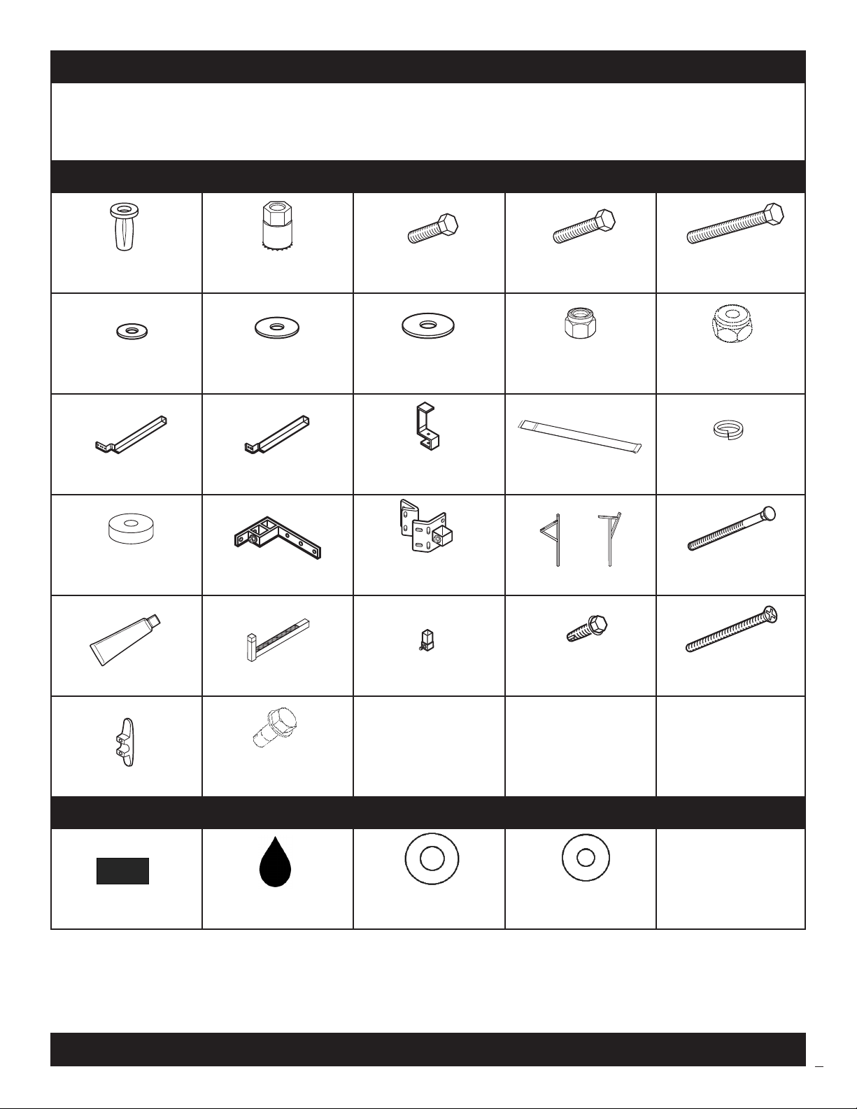
PARTS LIST
(9) 5/16-18
Blind Fastener
(4) #10
Flat Washer
(1) Front Leg Socket (1) Rear Leg Socket (1) Ladder Stop (2) Ladder Strap
(1)
Installation Tool
(15) 5/16"
Flat Washer
(2) 5/16-18 x 1"
Hex Head Bolt
(1) 3/8"
Flat Washer
(9) 5/16-18 x 1-1/4"
Hex Head Bolt
(4) 10-24
Nylon Lock Nut
(1) 5/16-18 x 2-1/4"
Black Oxide Bolt
(3) 3/8-16
Nylon Lock Nut
(9) 5/16"
Lock Washer
(1)
Floor Mounting Spacer
Front Mounting Bracket
(1)
(1)
Rear Mounting Bracket (2) Upright
(1) Silicone Sealant Tube (2) Extension (1) F-150 Adapter
(3) 3/8-16 x 3/4"
(2) Plastic Rope Cleat
Thread Cutting Bolt
ALUMINUM BED UPFIT KIT PARTS LIST - 32-0244
(4)
Vinyl Tape
(1)
Zinc Rich Primer
(28) 1/2" x 1"
Plastic Washer
OR
1450 1475
(2) 3/8-16 x 1"
Thread Cut Bolt
(4) 11/32" x 7/8"
Plastic Washer
(1) 3/8-16 x 3-1/4"
Carriage Bolt
(4) #10-24 x 2-3/4"
Machine Screw
©2015 KNAACK LLC
2
Page 3
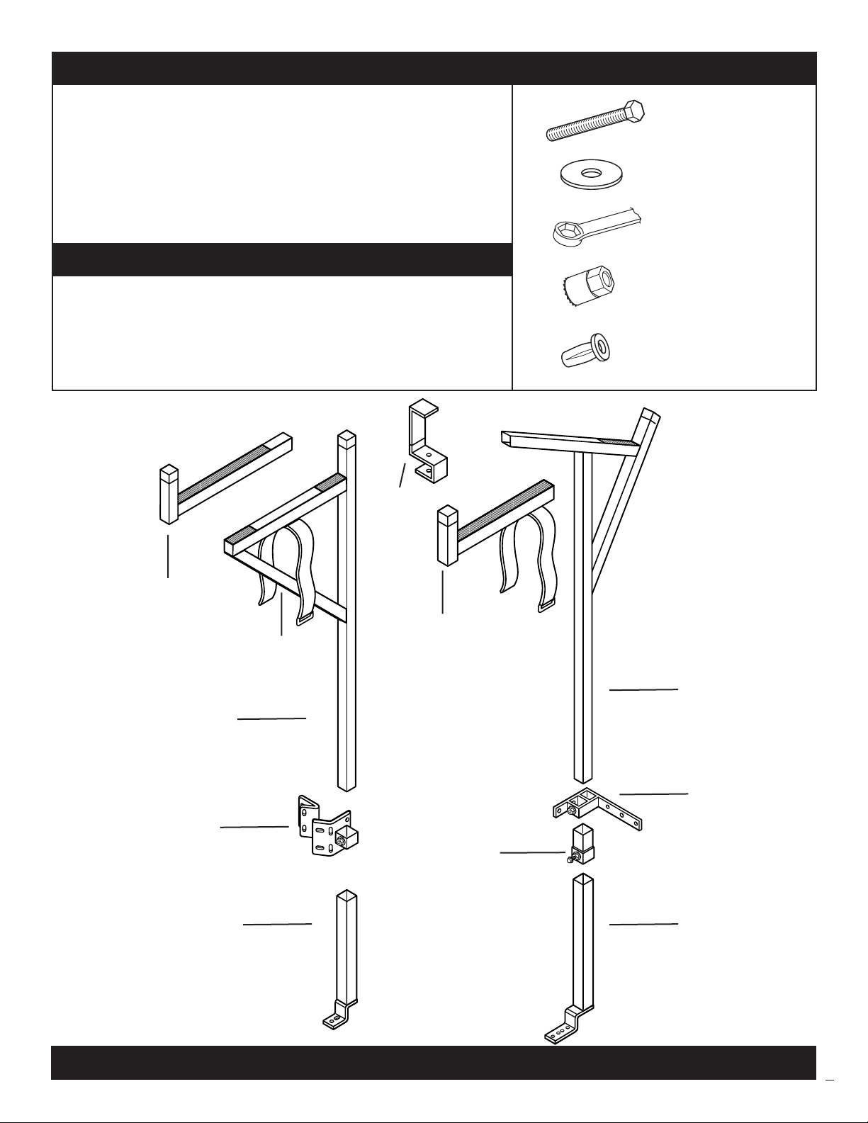
BLIND FASTENER INSTALLATION
Place a drop of oil on black oxide bolt for lubrication before assembling.
Place the Blind Fastener in the hole and use 1/2" or 7/16" wrench to
tighten black oxide bolt until fastener is fully seated (it will start out hard
and get easier as fastener “bulbs” out).
Make sure the Blind Fastener and Installation Tool do not turn during
installation.
ALUMINUM TRUCK BED INSTALLATION
Coat drilled holes with Zinc Rich Primer. Insert Blind Fastener through one
1/2" x 1" plastic washer. Insert Blind Fastener into drilled hole. Place
second 1/2" x 1" plastic washer through the bottom of the Blind Fastener.
Continue following installation instructions above to install Blind Fasteners.
STEEL WEEKENDER®
RACK ASSEMBLY
Ladder Stop
1450/1475
Black Oxide Bolt
Flat Washer
9/16" Wrench
Installation Tool
Blind Fastener
Extension
1450
(1-1/2” square tube)
Upright
1450
Rear Mounting Bracket
1450/1475
Front Leg Socket
1450/1475
Ladder Strap
1450/1475
Extension 1475
(1-3/4" square tube)
Upright
1475
Front Mounting Bracket
1450/1475
Ford F-150 Adapter
1450/1475
Front Leg Socket
1450/1475
©2015 KNAACK LLC
3
Page 4

INSTALLATION INSTRUCTIONS
Note: If your truck bed is constructed of aluminum, use zinc rich primer to coat drilled holes.
STEP 1
Note:
Mounting the Front Leg Socket
• The illustrations show installation on the
passenger side of the vehicle. For installation on
the driver side, simply reverse the parts.
• If the pickup has a bed liner, the liner may
need to be drilled, trimmed or cut for proper
installation of the product.
• The best mounting hole location is between
oor ribs. A oor spacer and/or two extra 5/16"
washers have been provided to ll the void. If
possible, rotate the leg socket assembly 90
degrees to the rear of the vehicle.
If installing on a 2004 Ford F-150 and newer vehicle, place
the F-150 Adaptor onto the front leg socket. Install and
tighten a 3/8-16 x 1" thread cutting bolt into the adaptor
to make a mark on the front leg socket. Remove adaptor
and drill a 7/16" pilot hole and then a 1/2" hole at the
indention mark of the thread cutting bolt on the leg socket.
Re-install the F150 adaptor onto the front leg socket. Do
not tighten the thread cutting bolt at this time.
Mark Mounting Bracket Holes
Center Punch Marks
Drill 7/32" pilot hole
Re-drill with 1/2" drill bit
FRONT OF BED
3/8-16 x 1"
Thread Cutting Bolt
(tighten the bolt enough to
mark the tube for drilling)
5/16-18 x 1-1/4"
Hex Head Bolt
5/16" Lock Washer
5/16" Flat Washer
SQUARE THE ASSEMBLY
TO THE BED
Installed
Blind
Fastener
Mark the Front Leg Socket
hole that aligns best on
the top of a oor rib
Insert the front leg socket into the front mounting bracket
as shown in the gure below. Hold the mounting bracket
ush with the top rail of the truck bed ensuring the front
leg socket assembly is plumb and square to the truck bed.
Mark and center punch the four holes of the front mounting bracket and front leg socket foot (see note above for
mounting to the truck bed oor).
Drill 7/32" pilot hole then re-drill
with 1/2" drill bit where the screw
marked the tube
Drill a pilot hole with a 7/32" drill bit in each marked hole. Then re-drill the
holes with a 1/2" drill bit. Install blind fasteners into each drilled hole.
ALUMINUM TRUCK BED INSTALLATION:
Follow additional instructions if mounting to an aluminum truck
bed as explained in the Blind Fastener Installation on page 3.
Take the front leg socket assembly, four 5/16-18 x 1-1/4" hex head bolts, four
5/16" lock washers and four 5/16" at washers and install as shown above.
Tighten all screws at this point ensuring assembly is square and plumb to the
truck.
Take a 3/8-16 x 1" thread cutting bolt and install into the front mounting
bracket. Tighten the thread cutting bolt enough to mark the front leg socket for
drilling.
Disassemble the front leg socket assembly, take the front leg socket and drill a
pilot hole with a 7/32" drill bit through the mark created in the previous step by
the thread cutting bolt. Then re-drill the hole with a 1/2" drill bit. Reassemble
the front leg socket assembly to the truck bed tightening all hardware except the
3/8-16 x 1" thread cutting bolt.
©2015 KNAACK LLC
4
Page 5

STEP 2A
Mounting the Rear Leg Socket (90º Degree Tailgate Stop)
Note:
• Skip Step 2A and proceed to Step 2B if you own a
Toyota Tacoma, Chevy Colorado, or GMC Canyon
with a 45-degree tail-gate stop.
• If the best mounting hole location is between oor
ribs, a oor spacer and/or two extra 5/16" at
washers have been provided to ll the void or rotate
the leg socket 90° to the rear of the vehicle if
possible.
Using the 5/16-18 x 1" hex head bolts, washers, and nylon lock
nuts fasten the rear mounting bracket plate 1 and 2 together.
The long end of the angle on plate 2 faces away from plate 1.
Insert the rear leg socket into the rear mounting bracket
assembly. Hold the mounting bracket assembly ush with the
tailgate stop ensuring that the rear leg is plumb and square to
the truck bed.
Mark the ve holes. Remove the assembly and center punch
each of the holes. Drill a 7/32" pilot hole, then re-drill each
hole using a 1/2" drill bit.
Install blind fasteners into each drilled hole.
ALUMINUM TRUCK BED INSTALLATION:
Follow additional instructions if mounting to an
aluminum truck bed as explained in the Blind Fastener
Installation on page 3.
Take the rear leg socket assembly, four 5/16-18 x 1-1/4"
hex head bolts, four 5/16" lock washers and four 5/16"
at washers and install as shown in gure below. (It may
be necessary to dis-assemble rear mounting bracket plate
1 and 2 in order to fasten plate 2 to the truck). Tighten all
fasteners at this time on the rear mounting bracket.
Take a 3/8–16 x 1" thread cutting bolt and install into the
rear mounting bracket as shown in the gure below. Tighten
the thread cutting bolt enough in order to mark the rear leg
socket for drilling.
Disassemble the rear leg socket assembly taking the rear
leg socket and drill a 7/32" pilot hole through the mark
created in the previous step with the thread cutting bolt.
Then re-drill the hole using a 1/2" drill bit. Reassemble
the rear leg socket assembly to the truck bed tightening all
hardware except the 3/8-16 x 1" thread cutting bolt.
LONG END OF ANGLE
3/8-26 x 1"
Thread Cutting Bolt
REAR LEG SOCKET
PLATE 2
PLATE 1
5/16-18 x 1-1/4"
Hex Head Bolt
5/16" Lock Washer
5/16" Flat Washer
©2015 KNAACK LLC
Mark the Front Leg Socket hole that
aligns best on the top of a oor rib
5
Page 6

STEP 2B
Mounting the Rear Leg Socket (45º Degree Tailgate Stop)
Note:
• For Toyota Tacoma, Chevy Colorado, or GMC
Canyon with a 45-degree tail-gate stop.
• If the best mounting hole location is between
oor ribs, a oor spacer and/or two extra
5/16" at washers have been provided to ll
the void. Or rotate the leg socket 90° to the
rear of the vehicle if possible.
Insert the rear leg socket into the rear mounting bracket
plate 1 as seen in gure below (plate 2 will not be
used). Hold the mounting bracket assembly ush with
the tailgate stop ensuring that the rear leg is plumb and
square to the truck bed.
Mark the ve holes. Remove the assembly and center
punch each of the holes. Drill a 7/32" pilot hole, then
re-drill each hole using a 1/2" drill bit.
Install blind fasteners into each drilled hole.
ALUMINUM TRUCK BED INSTALLATION:
Follow additional instructions if mounting to an aluminum truck
bed as explained in the Blind Fastener Installation on page 3.
Take the rear leg socket assembly, four 5/16-18 x 1-1/4" hex head
bolts, four 5/16" lock washers and four 5/16" at washers and
install as seen in Figure below. Tighten all fasteners at this time on
the rear-mounting bracket.
Take a 3/8–16 x 1" thread cutting bolt and install into the rear
mounting bracket as shown in the gure below. Tighten the thread
cutting bolt enough to mark the front leg socket for drilling.
Disassemble the rear leg socket assembly taking the rear leg socket
and drill a 7/32" pilot hole through the mark created in the previous
step with the thread cutting bolt. Then re-drill the hole using a 1/2"
drill bit. Reassemble the rear leg socket assembly to the truck bed
tightening all hardware except the 3/8-16 x 1" thread cutting bolt.
REAR LEG SOCKET
LONG END OF ANGLE
PLATE 1
3/8-26 x 1"
Thread Cutting Bolt
5/16-18 x 1-1/4”
Hex Head Bolt
5/16” Lock Washer
5/16” Flat Washer
Mark the Front Leg Socket hole that
aligns best on the top of a oor rib
©2015 KNAACK LLC
6
Page 7

STEP 3
Installing the Front Upright
Take one upright and insert into the front
leg socket assembly. Tighten the 3/8-16
x 1" thread cutting bolt installed in Step
1 in the front mounting bracket. Take one
extension and insert it into the upright. After
tightening at the desired location, seal the
joint between the two tubes with the provided
silicone sealant. Take the ladder stop, one
3/8-16 x 3/4" carriage bolt, one 3/8" at
washer and one 3/8-16 nylon lock nut and
install onto the upright. Take the one strap
and install it onto the bracket.
LADDER STOP
3/8-16 x 3/4'
Thread Cutting Bolt
(locks the extension
to the leg)
3/8-16 x 3-13/4"
Carriage Bolt
3/8" Lock Washer
3/8-16 Nylon Lock Nut
Model 147885 Install the Ladder
Stop on the Extension
STEP 4
Installing the Rear Upright
Take the remaining upright and insert into
the rear leg socket assembly. Tighten the
3/8-16 x 1" thread cutting bolt installed in
Step 2 in the rear mounting bracket.
Secure ladder with
hook and loop straps
when transporting.
Secure or remove
straps when not being
used.
Take the remaining extension and insert it
into the upright as shown in Step 3. After
tightening at the desired location, seal the
joint between the two tubes with the provided
silicone sealant. Take the remaining ladder
strap and install it onto the bracket as shown
in Step 3.
STEP 5 STEP 6
Installing the Rope Cleats
The two rope cleats are to be mounted where desired
on the upright.
Apply sealant around holes before assembling.
#10-24
Flat Washer
#10-24 x 2-3/4"
Machine Screw
2" minimum
2" minimum
Securing a Ladder to the Rack
Carefully place a ladder on the rack, and check door
entry and head clearance. If clearance is ample, and
if desired, the uprights may be shortened as long as a
minimum of 2" above the cab roof is maintained, see
Step 4. Remove and cut the uprights if desired. Note
that you need to cut from the bottom of the upright.
Double check the measurement before cutting. Secure
ladder with the provided ladder straps when transporting.
Secure or remove ladder straps when not being used.
#10-24
Nylon Lock Nut
©2015 KNAACK LLC
7/32" Hole
7
Page 8

KNAACK LLC LIMITED LIFETIME WARRANTY FOR WEATHER GUARD® PRODUCTS
WEATHER GUARD® Products — Limited Lifetime Warranty
(Purchased on or after 1/1/2009)
KNAACK LLC (the “Manufacturer”) warrants to the original purchaser only that WEATHER GUARD® Truck and Van Products (the “WEATHER GUARD®
Product”) will be free from defects in material and workmanship from the date of purchase and continuing for the expected lifetime of the WEATHER
GUARD® Product. A copy of the original sales receipt must be supplied to the Manufacturer at the time a warranty claim is made. This warranty terminates
if the original purchaser transfers the WEATHER GUARD® Product to any other person.
What is Covered
All WEATHER GUARD® Products identied above that are purchased on or after January 1, 2009.
What We Will Do To Correct Problems
Subject to the limitations and exclusions described in this limited warranty, the Manufacturer will remedy defects in materials or workmanship by
providing one of the following remedies at its option and without charge to the original purchaser for parts or labor: (a) repairing the defective portion of
the WEATHER GUARD® Product or (b) replacing the entire WEATHER GUARD® Product. In addition, the Manufacturer may elect at its option, not to repair
or replace the WEATHER GUARD® Product, but rather issue to the original purchaser a refund equal to the purchase price paid for the WEATHER GUARD®
Product or a credit to be used toward the purchase of a new WEATHER GUARD® Product.
What is Not Covered
This limited warranty expressly excludes:
• Defects caused by normal wear and tear, cosmetic rust, scratches, accidents, unlawful vehicle operation, or modication to the product, or any
types or repair of a WEATHER GUARD® Product other than those authorized or provided by the Manufacturer.
• Defects resulting from conditions beyond the Manufacturer’s control including, but not limited to misuse, overloading, or failure to assemble, mount
or use the WEATHER GUARD® Product in accordance with the Manufacturer’s written instructions or guidelines included with the WEATHER GUARD®
Product or made available to the original purchaser.
• Damage to the contents of the box or vehicle.
• TO THE EXTENT PERMITTED BY LAW, IN NO EVENT SHALL THE MANUFACTURER BE LIABLE FOR ANY INCIDENTAL, SPECIAL, INDIRECT, OR CONSEQUENTIAL
DAMAGES, INCLUDING ANY ECONOMIC LOSS, WHETHER RESULTING FROM NONPERFORMANCE, USE, MISUSE OR INABILITY TO USE THE WEATHER
GUARD® PRODUCT OR THE MANUFACTURER’S NEGLIGENCE.
No Other Express Warranty Applies
This Limited Lifetime Warranty is the sole and exclusive warranty for WEATHER GUARD® Products. No employee, agent, dealer, or other person is
authorized to alter this warranty or make any other warranty on behalf of KNAACK LLC.
Notication Procedures
If the WEATHER GUARD® Product does not conform with the terms of this limited warranty, the original owner must promptly notify the Manufacturer in
writing upon discovery of the nonconformity. In order to receive the remedies under this limited warranty, the warranty claim must describe the nature of
the nonconformity, and a copy of the original sales receipt, invoice, bill or other proof of purchase must accompany the claim. Repairs or modications
made to the WEATHER GUARD® Product by other than the Manufacturer or its authorized agent will nullify this limited warranty. Coverage under this
limited warranty is conditioned at all times upon the owner’s compliance with these required notication and repair procedures. Warranty claims must
include reciprocal contact information and may be made via certied mail to:
KNAACK LLC
ATTN: Warranty Claims
420 E. Terra Cotta Avenue
Crystal Lake, IL 60014
If you have any questions,
please call toll free at 1-800-456-7865
WEATHER GUARD® Products are protected by one or more of the following patents:
U.S. - 5145087, 5308126, 4509787, 4573731, 4618083, D-346355, D-346994, D-353574; Canada - 1218968, 1224230, 1235100 and; U.K. - 2233036. Other patents pending.
©2015 KNAACK LLC
WEATHERGUARD.COM
WEATHERGUARD.COM
Part No. 24-0192 REV. D ECN 5583 05/15
8
 Loading...