

Page 1
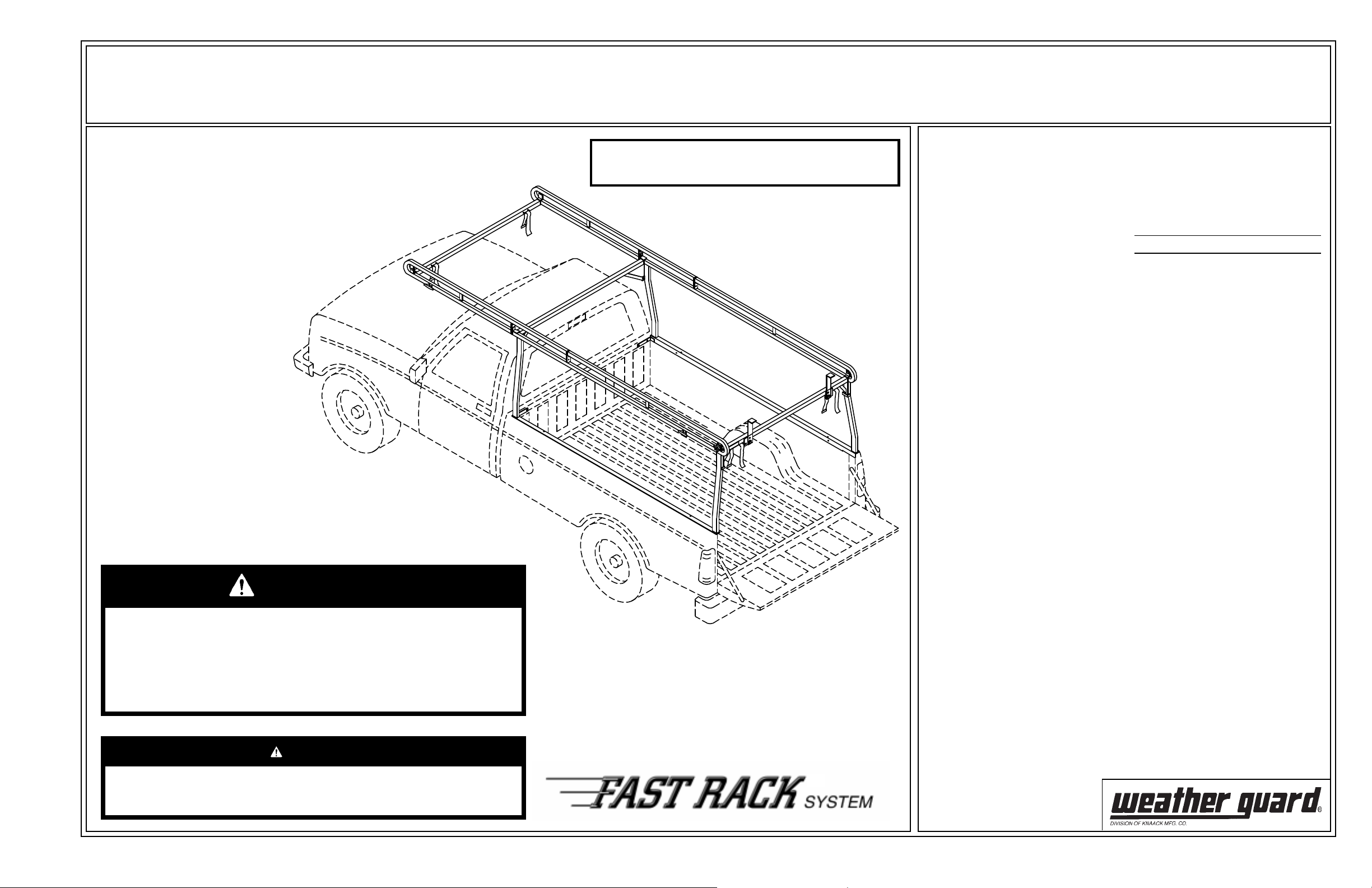
ASSEMBLY AND INSTALLATION INSTRUCTIONS
Model 1280 Full Size Truck Rack ( 8 ft. Bed)
IMPORTANT
BEFORE YOU
BEGIN
Read these instructions
and warnings completely
before assembly and
installation.
NOTE: If your vehicle has a bedliner
you may need to drill, trim, or cut
the liner for proper installation of
this product. If the bedliner extends
over the top rail on the sides of the
bed, this rack will not work unless
the entire over the top section is removed.
Approximate Assembly and Installation time:
1 hour 18 min. per unit (1.299 hrs.)
Depending on truck equipment installation experience.
PARTS LIST
1 - Driver Side Leg/Base/Rail
1 - Passenger Side Leg/Base/Rail
1 - Driver Side Front Rail
1 - Passenger Side Front Rail
Tube, E-6000 Sealant
NOTE: Crossmembers are packaged
separately per vehicle model
1281 = GM Crossmembers
1282 = Dodge Crossmembers
Model 1500 through
2001
Models 2500/3500
through 2002
1283 = Ford Crossmembers
1284 = Super Duty Ford
Crossmembers
1287 = Dodge Crossmembers
2002 Model 1500 and
2003 Models 2500/3500
and newer
BOLT KIT
Bolt Kit #32-0102 is provided with
your ladder rack. Check this bolt kit
to be sure the following parts are
included:
Quan. Description
8 5/16-18 Nylon Lock Nut
6 5/16-18 x 1" Carriage Bolt
4 5/16-18 x 1-1/2" Hex Hd.
Bolt
2 5/16-18 x 1-1/4" Carriage
Bolt
8 5/16 Flat Washer
4 5/16" Lock Washer
4 5/16-18 Blind Fastener
4 1/4-20 x 1-1/4" Hex Hd.
8 1/4-20 Nylon Lock Nut
12 1/4 Flat Washer
1 Blind Fastener Installation
Tool
1 5/16-18 x 2-1/4" Black
Oxide Bolt
4 Black Tie Downs
8 10-24 x 2-3/4" F.H. Screws
8 10-24 Nylon Lock Nuts
4 1/4-20 x 1-1/2" Carriage Bolt
WARNING
This product is only intended for, and only safe for, transporting ladders,
lumber, pipe and other similar materials. It is the responsibility of the
user to secure these materials to the rack before transporting. Any
modifications made to this product, or use of this product for any other
purpose than its intended use, will create a hazardous condition that will
cause serious personal injury or property damage.
CAUTION
Never load your rack to exceed the safe rated capacity of your vehicle.
Heavy loads carried high can dangerously alter the center of gravity.
TOOLS REQUIRED
Electric Drill
Drill Bits - 7/32", 1/4", & 1/2"
Screwdriver - common
Open or Box End Wrenches - 7/16",
1/2", & 9/16"
3/8" Drive Ratchet
Sockets - 7/16" & 1/2"
C-clamp
Rev. A 7/04 Part No. 24-0136
®
Page 2
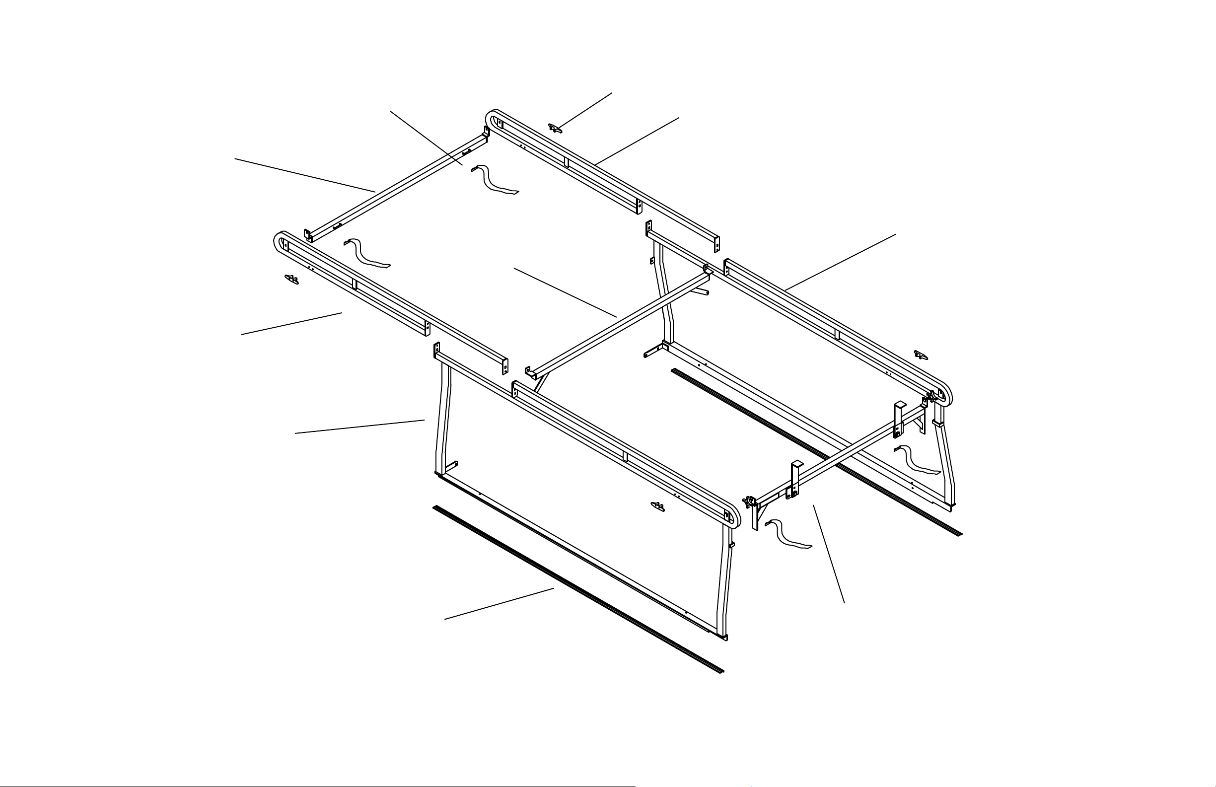
Tie Down
Front Crossmember
Driver Side
Front Rail
Strap (4)
Passenger Side
Front Rail
Passenger Side
Leg/Base/Rail
Center Crossmember
Driver Side
Leg/ Base/Rail
Mounting Pad
Rear Crossmember
2
Page 3

STEP 2. Tie Down Installation.
Install tie downs where desired.
Put E-6000 sealant on the back of the
tie downs and under nuts before installing.
STEP 3. Mounting Pad Installation.
Place pads on the top of the bed. It may be necessary to
hold the pads in place with small pieces of tape.
10-24 x 2-3/4"
Flat Head Screw
7/32" Hole
CAUTION
To keep debris out of your
eyes when drilling, always
wear protective eyewear.
Mounting
Pad
Tie Down
Inside of
truck bed
10-24 Nylon
Lock Nut
STEP 1. Rail Assembly.
Driver Side (shown)
or Passenger Side
Decal
5/16-18 x 1"
Carriage Bolt
This bolt does not get installed until
the Center Crossmember is attached.
5/16 Flat
Washer
5/16-18 Nylon
Lock Nut
STEP 4. Rail and Rear Crossmember Installation
With the help of at least two other people lift one of the
assembled sections onto the truck. One person should be in
the truck to hold the first section while the other section is
being lifted into position. Once both sections are positioned,
install the rear crossmember as shown in STEP 5.
3
Page 4

STEP 6. Front Crossmember Assembly.
5/16 Flat
Washer
5/16-18 Nylon
Lock Nut
5/16-18 x 1"
Carriage Bolt
5/16-18 x 1-1/4"
Carriage Bolt
5/16-18 x 1"
Carriage Bolt
STEP 7. Center Crossmember Assembly.
5/16 Flat
Washer
5/16-18 Nylon
Lock Nut
STEP 5. Rear Crossmember Assembly.
(Ladder Stop not shown for clarity)
4
Page 5

PERFORM THE FOLLOWING STEPS TO THE DRIVER SIDE
& PASSENGER SIDE (Passenger Side Shown)
STEP 11. Unfasten Side, Move Rack out of the Way,
Redrill Front Holes, and Install Blind Fasteners
STEP 12. Install Front, Top, and Side Fasteners
STEP 8. Tape Washer, Clamp, and Drill Front Side
Tape a 5/16" Flat Washer
between front of Mounting Base
and bed
Drill
1/4" dia.
Hole
STEP 9. Unclamp, Remove Flat Washer, and Fasten Side
1/4-20 x 1-1/4"
Hex Hd. Bolt
Drill (2)
1/2" dia.
Hole
5/16-18
Blind Fastener
5/16" Lock
Washer
5/16-18 x 1-1/2"
Hex Hd. Bolt
1/4" Flat
1/4-20 x 1-1/4"
Hex Hd. Bolt
Washer
STEP 13. Clamp, Drill, and Fasten Rear Side
1/4-20 x 1-1/4"
Hex Hd. Bolt
1/4-20 x 1-1/2"
Carriage Bolt
1/4-20 Nylon
Lock Nut
1/4" Flat
Washer
STEP 10. Drill Front and Top
Centered in
3/8" dia. holes
1/4" Flat
Washer
1/4-20 Nylon
Lock Nut
Drill
1/4" dia.
Hole
INSTALLATION PROCEDURE USING BLIND FASTENERS
Place a drop of oil on the
black oxide bolt before
assembling as shown at
right. Place the Blind
Fastener in the hole and
Black
Oxide
Bolt
Flat
Washer
use a 1/2 or 7/16
wrench to tighten black
hex bolt until the blind
fastener is fully seated.
When setting black hex
9/16
Wrench
bolt, it will start out hard.
As the Blind Fastener
bulbs out it will get
easier, until it bottoms
Installation
Tool
out or sets. Make sure
the Blind Fastener and
Installation Tool do not
turn during installation.
Blind
Fastener
Drill
1/4" dia.
Hole
1/4-20 Nylon
Lock Nut
STEP 14. Remove Clamp, Drill, and Fasten Rear Top
1/4-20 x 1-1/2"
Carriage Bolt
1/4" Flat
Washer
Drill
1/4" dia.
Hole
Drill (2)
1/4" dia.
Hole
1/4-20 Nylon
Lock Nut
5
Page 6

Bolt Chart
Nylon Lock Nuts
10-24 x 2-3/4"
F.H. Screw
5/16-18 x 1-1/2"
Hex Hd. Bolt
10-24 5/16-18
1/4-20 x 1-1/4"
Hex Hd. Bolt
WEATHER GUARD® PRODUCT
REFINISHING PROCEDURES
All WEATHER GUARD® products are finished with a polyester powder coating, and it is important to follow these procedures to get proper adhesion. As Knaack
Manufacturing Co. cannot control the finishing of the products, the warranty for WEATHER GUARD® products on paint is not applicable on refinished products.
5/16-18 x 1-1/4"
Carriage Bolt
5/16-18 x 1"
Carriage Bolt
1/4-20
1/4-20 x 1-1/2"
Carriage Bolt
WARNING
Ladders must be secured per ANSI
standard A142.2-1990 paragraph 8.4.4. Ladder
damage will occur from road shock and
vehicle vibration if the ladder is not properly
secured to the ladder rack. Bouncing and side
to side motion of a improperly secured ladder
will cause wear and weaken the ladder. Using
a damaged ladder could lead to a structural
collapse and could result in a serious injury or
death.
1. Sand the surface to be painted with 180-200 grit sand paper to rough up the surface. This should be followed by wet sanding with a 400 grit wet or dry paper.
2. Wipe down the sanded surface with ketone based thinner. This removes the dust and softens the powder coating for better paint adhesion.
3. Wipe sanded area with a tack rag to remove loose dust and particles before painting.
NOTE: Do not use a lacquer over the powdered coating.
- NOTICE -
Any modification or unintended use of this product shall immediately void all manufacturers warranties.
Manufacturer disclaims all liability for injuries to persons or property resulting from any modification to,
or unintended use of this product.
If you have any questions, please give us a call. Call Toll Free 1-800-456-7865
WEATHER GUARD® products are protected by one or more of the following patents or trademarks:
U.S. - 2228051, 842268, 1661625, 1663369, 4509787, 2434963; Canada - 282725, 1218968; U.K. - 1400720; N.Z. - 296049; Aus. - 761964
KNAACK MANUFACTURING COMPANY
420 E. TERRA COTTA AVENUE - CRYSTAL LAKE, ILLINOIS, USA 60014 - 815-459-6020
©2004 Knaack Manufacturing Company
 Loading...