

Page 1
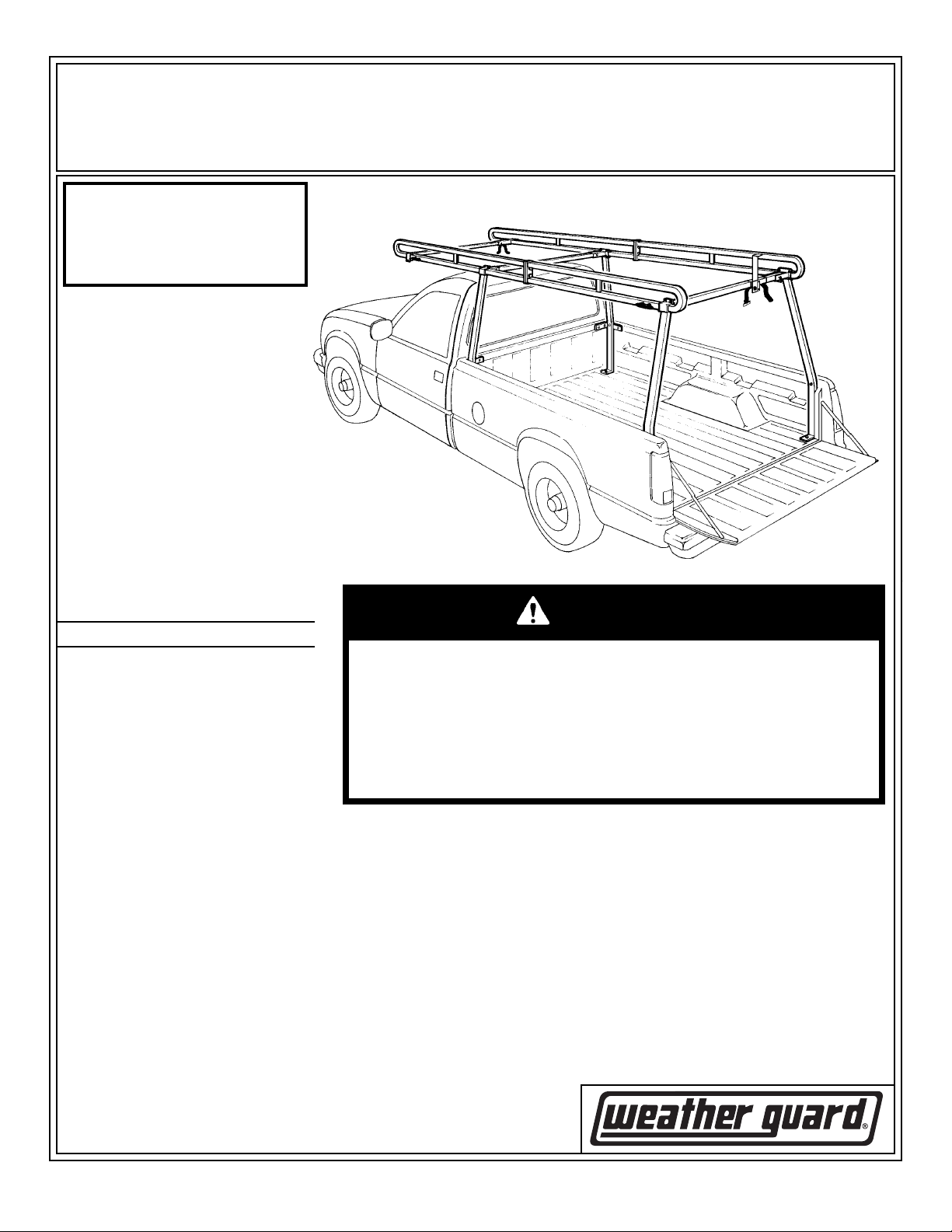
ASSEMBLY AND INSTALLATION INSTRUCTIONS
Ladder Rack - Models 1245 and 1275
Model 1245 - Full Size Pickup Short Beds Model 1275 - Full Size Pickup Long Beds
Approximate Assembly and
Installation Time:
5 hours per unit (5.0 hrs.)
depending on truck equipment
installation experience.
IMPORTANT
BEFORE YOU BEGIN
Read these instructions and
warnings completely before
installing.
BOLT KIT
Bolt Kit #32-0105 is provided with
your ladder rack. Check this bolt kit
to be sure the following parts are
included:
Quan. Description
WARNING
4 3/8-16 x 3/4" Hex Head,
Thread Cutting
20 5/16-18 Nylon Lock Nut
4 3/8-16 x 1-1/4" Carriage Bolt
4 3/8" Flat Washer
4 3/8-16 Nylon Lock Nut
4 5/16-18 x 2" Hex Hd. Bolt
2 5/16-18 x 2-3/4" Hex Hd. Bolt
12 5/16-18 x 1-1/4" Hex Hd. Bolt
16 5/16-18 x 3/4" Carriage Bolt
34 5/16 Flat Washer
14 5/16" Lock Washer
14 5/16-18 Blind Fastener
1 Installation Tool
2 5/16-18 x 2-1/4" Black
Oxide Bolt
2 5/16" x 2-3/4" Latch Pins
4 Black Tie Downs
8 10-24 x 2-3/4" F.H. Screws
8 10-24 Nylon Lock Nuts
2 Sq. Cap Plugs (black)
2 5/16-18 x 2" Carriage Bolt
4 5/16 x 2" Dia. Blk. Oxide
Flat Washer
This product is only intended for, and only safe for, transporting
ladders, lumber, pipe and other similar materials. It is the responsibility of the user to secure these materials to the rack before transporting. Any modifications made to this product, or use of this
product for any other purpose than its intended use, could create
a hazardous condition that can cause serious personal injury or
property damage.
PARTS LIST
4 - Top Rail Halves
Cushion Strip (bulk)
2 - Closed Top Tube Sleeves
2 - Open Top Tube Sleeves
4 - Legs
2 - Crossmembers (open ends)
1 - Front Crossmember
1 - Front Crossmember Sleeve
2 - Bed Reinforcing Brackets
2 - Front Leg Spacer
Tube, Sealant
1 - Ladder Stop
2 - Straps
Electric Drill
Drill Bits - 5/16", 3/8" & 1/2"
3/8" Open or Box End Wrench
1/2" Open or Box End Wrench (2)
9/16" Open or Box End Wrench (2)
Screwdriver - common
Framing Square
Pencil or Marker
TOOLS REQUIRED
1
Part No. 24-0132 REV. B ECN 5315 05/13
Page 2
NOTE:
Some vehicle manufacturers
require a manufacturer supplied
after market reinforcing kit be
installed prior to mounting any
kind of ladder rack or truck box
on your vehicle. Kits can be
purchased from your local
vehicle dealership. Contact
your local dealer to see if your
vehicle is effected.
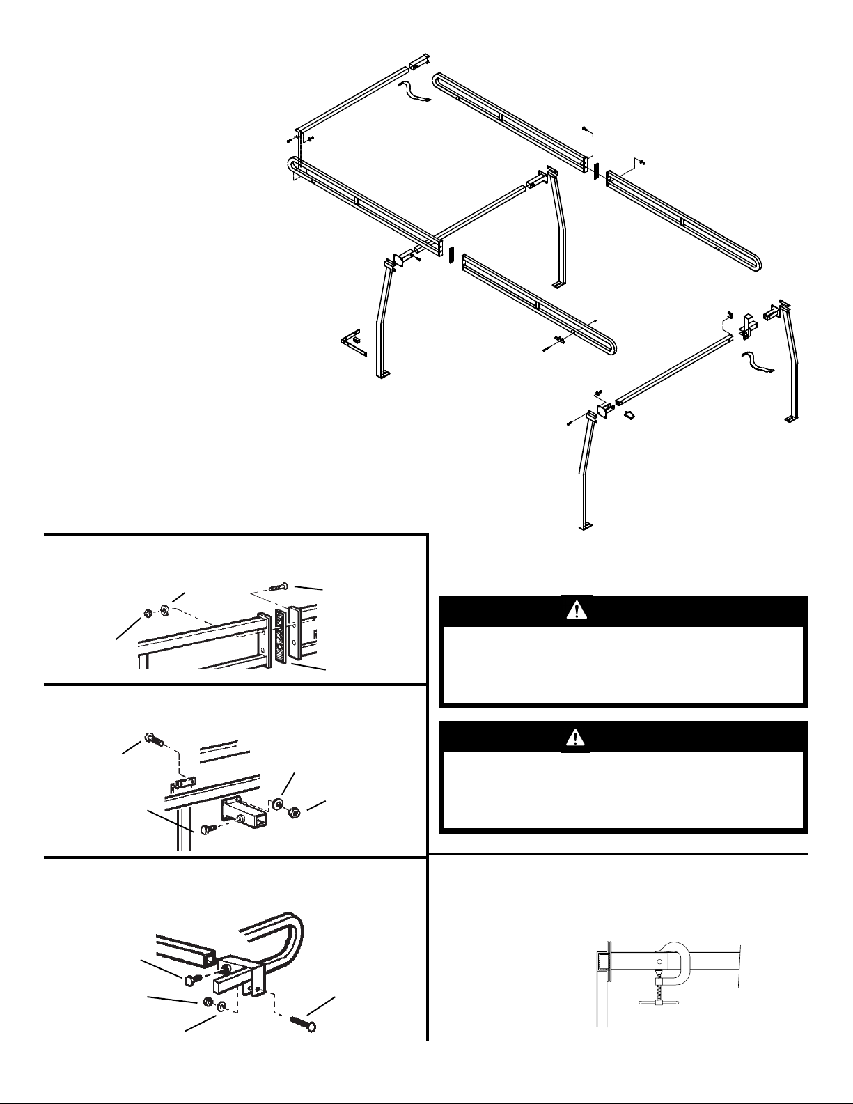
STEP 1. Bolt front and rear rail halves together (two bolts
per rail).
3/8-16
Nylon Lock
Nut
3/8" Flat
Washer
3/8-16 x 1-1/4"
Carriage Bolt
Cushion
Strip
STEP 2. Attach all legs and sockets. Do not tighten. (Four bolts
required per leg)
CAUTION
To keep debris out of your eyes when checking
the underside of the vehicle, or when drilling,
always wear protective eyewear.
5/16" Flat
5/16-18 x 3/4"
Carriage Bolt
3/8-16 x 3/4" Hex
Head Thread
Cutting Bolt
Washer
5/16-18 Nylon
Lock Nut
STEP 3. Assemble front crossmember.
Turn crossmember upside down for clearance on king cabs.
3/8-16 x 3/4"
Thread
Cutting Bolt
5/16-18 Nylon
Lock Nut
5/16" Flat Washer
5/16-18 x 2"
Carriage Bolt
CAUTION
Never load your rack to exceed the safe rated
capacity of your vehicle. Heavy loads carried
high can dangerously alter the center of gravity.
STEP 4. Check width of rack and truck bed. If rack is nar-
rower, clamp rear crossmember in rear open sockets temporarily,
but DO NOT drill, proceed to Step 5. If the rack is too wide, remove rear cross-member and cut to fit. Note - Double check all
measurements before cutting.
2
Page 3

WARNING
All floor mounting bolts near the gas tank area
should be installed from the underside of the vehicle, to guard against the gas tank being punctured in the event of a collision. This would mean
not using Blind Fasteners in this area.
WARNING
Prior to drilling, so as not to cut or puncture fuel
tanks, fuel lines, brake lines, electric wires, etc.,
check under vehicle for locations.
STEP 5. If the manufacturers reinforcing kit is not required on
your vehicle, install two Bed Reinforcing Brackets.
See Blind Fastener instructions for installation.
1/2" Hole
5/16-18
Blind Fastener
5/16" Flat
Washer
5/16" Lock Washer
5/16" Lock
Washer
Install this
bolt when using
Step 7 Option
5/16-18 x 1-1/4"
Hex Head Bolt
3/8" Hole
STEP 6. Rear leg installation.
For maximum strength, the rear legs must be bolted to the tailgate
stops (as shown).
A) Before drilling leg mounting holes, use a framing square to insure accuracy of alignment.
B) Fasten leg to floor and leg to side.
STEP 7. Front leg installation.
(See STEP 7. Option for installation due to obstructions in the bed
floor.)
5/16-18 x 2"
Hex Hd. Bolt
3/8" Hole
5/16" Lock
Washer
5/16-18 x 1-1/4"
Hex Hd. Bolt
5/16" Lock
Washer
1/2" Hole
2" Dia. Leg
Washer
5/16-18 Blind
Fastener
5/16" Flat Washer
5/16-18 x 2"
Hex Hd. Bolt
5/16-18 x 1-1/4"
Hex Hd. Bolt
5/16" Lock
Washer
5/16" Flat Washer
1/2" Hole
2" Dia. Leg Washer
1/2" Hole
5/16-18 Blind
Fastener
STEP 7. Option - Front Leg Spacers are provided.
3/8" Hole
Front Leg
Spacer
5/16-18
Nylon
Lock Nut
5/16" Flat
Washer
3/8" Holes
5/16-18 x 2-3/4"
Hex Hd. Bolt
2" Dia. Leg
Washer
STEP 8. Tightening fasteners.
Tighten all nuts and bolts in the following order:
First - leg bolts. Tighten evenly so crossmember sleeves stay
parallel. (Start with rear legs)
Second - top of legs to rails, center and rear. Make sure bolts
are evenly tightened.
Third - crossmembers (center and front only).
STEP 10. Tie Downs.
Install four Tie Downs where desired. We suggest putting
sealant on the back of the tie downs and under nuts before
installing.
10-24 Nylon
Lock Nut
Tie Down
10-24 x 2-3/4"
Flat Head Screw
STEP 9. Rear Crossmember.
Drill a 3/8" hole through the
sleeve and crossmember to
accept the insertion of the
Latch Pin. The wire loop of
the latch pin swings around
the sleeve and over the end
of the pin.
STEP 11. Ladder Stop.
Remove rear Crossmember and slide Ladder
Stop onto it. Install Crossmember on rack. With a Ladder on the
rack, locate the Ladder Stop inside
of the ladder and then secure. Insert a
strap through the loop on the Ladder
Stop and on the front Crossmember
Socket. Refer to the warning decal on
the Ladder Stop.
3/8-16 x 3/4"
Thread Cutting
Bolt
3
Square
Cap
Plug
Latch
Pin
Strap
Page 4

STEP 12. Sealant.
Seal all nuts, bolts, and crossmember to
sleeve seam with sealant.
WARRANTY WILL BE VOID IF
SEALANT IS NOT APPLIED TO
ALL SEAMS AND CREVICES
INSTALLATION PROCEDURE USING BLIND FASTENERS
WARNING
Black
Prior to drilling, so as not to
cut or puncture fuel tanks,
fuel lines, brake lines, electric
wires, etc., check under vehicle for locations.
Oxide
Bolt
Flat
Washer
WARNING
Ladders must be secured per
ANSI standard A142.2-1990 paragraph 8.4.4. Ladder damage will
occur from road shock and vehicle vibration if the ladder is not
properly secured to the ladder
rack. Bouncing and side to side
motion of a improperly secured
ladder will cause wear and
weaken the ladder. Using a damaged ladder could lead to a structural collapse and could result in
a serious injury or death.
Place a drop of oil on the black oxide bolt
before assembling as shown on right. Place
the Blind Fastener in the hole and use a
1/2 or 7/16 wrench to tighten black hex
bolt until the blind fastener is fully seated.
When setting black hex bolt, it will start out
hard. As the Blind Fastener bulbs out it
will get easier, until it bottoms out or sets.
Make sure the Blind Fastener and Installation Tool do not turn during installation.
10-24
Nylon Lock Nuts
5/16
3/8
9/16
Wrench
Installation
Tool
Blind
Fastener
Bolt Size Chart
WEATHER GUARD® PRODUCT
REFINISHING PROCEDURES
All WEATHER GUARD® products are finished
with a polyester powder coating, and it is important to follow these procedures to get
proper adhesion. As Knaack LLC cannot
control the finishing of the prod-ucts, the
warranty for WEATHER GUARD®
products on paint is not applicable on refinished products.
1. Sand the surface to be painted with 180-200
grit sand paper to rough up the surface. This
should be followed by wet sanding with a 400
grit wet or dry paper.
2. Wipe down the sanded surface with ketone
based thinner. This removes the dust and softens the powder coating for better paint adhesion.
3. Wipe sanded area with a tack rag to remove
loose dust and particles before painting.
NOTE: Do not use a lacquer over the
powder coating
10-24 x 2-3/4"
F.H. Screw
5/16-18 x 2"
Hex Hd. Bolt
5/16-18 x 2"
Carriage Bolt
5/16-18 x 2-3/4"
Hex Hd. Bolt
5/16-18 x 1-1/4"
Hex Hd. Bolt
3/8-16 x 1-1/4"
Carriage Bolt
5/16-18 x 3/4"
Carriage Bolt
3/8-16 x 3/4"
Bolt, Thd. Cut
- NOTICE -
Any modification or unintended use of this product shall immediately void all manufacturers warranties. Manufacturer disclaims all
liability for injuries to persons or property resulting from any modification to, or unintended use of this product.
If you have any questions, please give us a call. Call Toll Free 1-800-456-7865
WEATHER GUARD® products are protected by one or more of the following patents or trademarks:
U.S. - 4509787, 842268, 1661625, 1663369, 2228051, 2434963; Canada - 1218968, 282725; U.K. - 1400720; NZ - 296049; Aus.- 761964
KNAACK LLC
420 E. TERRA COTTA AVENUE - CRYSTAL LAKE, ILLINOIS, USA 60014 - 815-459-6020
© 2002 Knaack LLC
4
Part No. 24-0132 REV. B ECN 5315 05/13
 Loading...