

Page 1
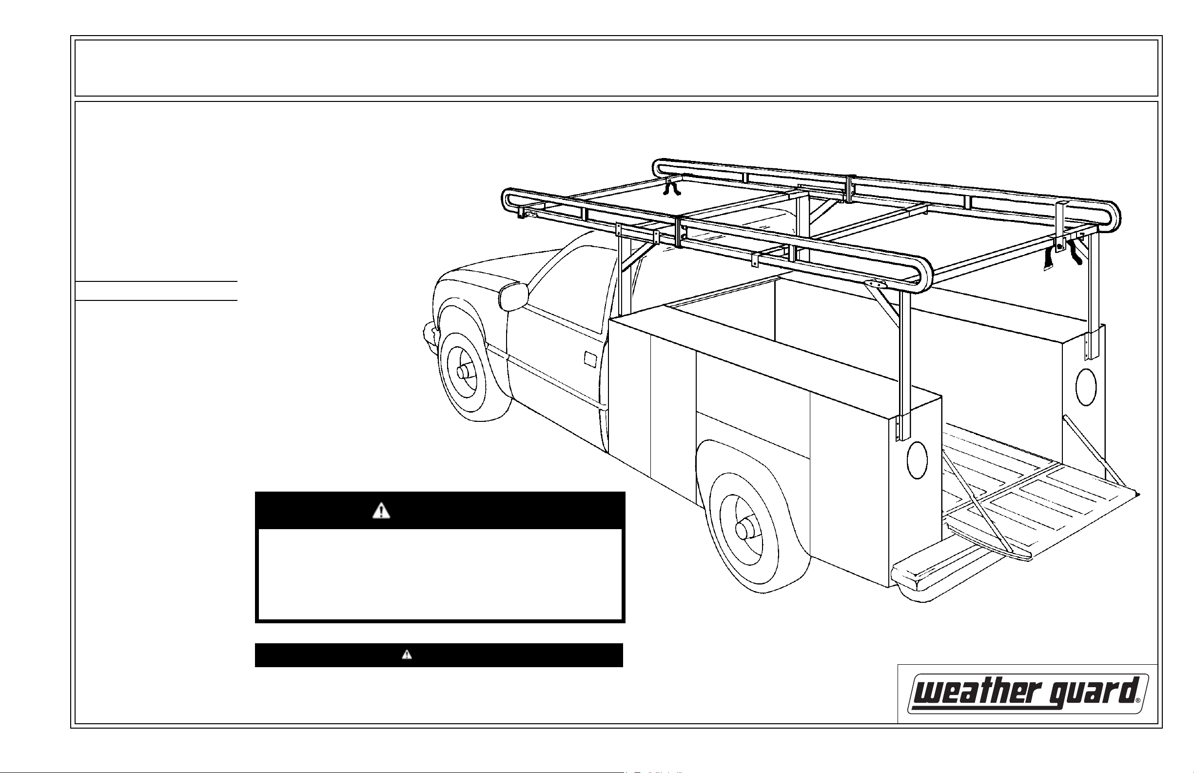
IMPORTANT
BEFORE YOU BEGIN
ASSEMBLY AND INSTALLATION INSTRUCTIONS
Model 1225 Service Body Ladder Rack
Read these instructions and
warnings completely before
installing.
BOLT KIT
Bolt Kit #32-0110 is provided with
your ladder rack. Check this bolt kit
to be sure the following parts are
included:
Quan. Description
5 3/8-16 x 3/4" Hex Head,
Thread Cutting
24 3/8-16 x 1-1/2" Carriage
Bolt
4 3/8-16 x 1-1/4 Carriage Bolt
28 3/8" Flat Washer
28 3/8-16 Nylon Lock Nut
4 5/16-18 x 2" Carriage Bolt
8 5/16-18 x 1" Carriage Bolt
12 5/16 Flat Washer
12 5/16-18 Nylon Lock Nut
2 5/16" x 2-3/4" Snapper Pin
4 Rope Cleat (black)
8 10-24 x 2-3/4" F.H. Screw
8 10-24 Nylon Lock Nut
2 Square Cap Plug (black)
MAXIMUM
LOAD CAPACITY
1000 lbs.
(evenly distributed)
* See Bolt Chart on back page for
fastener reference
TOOLS REQUIRED
Electric Drill
Drill Bits - 7/32", 3/8", 7/16" & 1/2
3/8 Open or Box End Wrench
1/2" Open or Box End Wrench (2)
9/16" Open or Box End Wrench (2)
Screwdriver - common
Framing Square
Pencil or Marker
Tape Measure
Hack Saw
Hammer
WARNING
This product is only intended for, and only safe for, transporting ladders,
lumber, pipe and other similar materials. It is the responsibility of the
user to secure these materials to the rack before transporting. Any
modifications made to this product, or use of this product for any other
purpose than its intended use, will create a hazardous condition that will
cause serious personal injury or property damage.
CAUTION
Never load your rack to exceed the safe rated capacity of your vehicle.
Heavy loads carried high can dangerously alter the center of gravity.
1
Part No. 24-0135 REV. D ECN 5315 05/13
Page 2
NOTE: Truck beds and boxes vary in
width and height. Crossmembers and
legs may have to be cut to fit your box.
Crossmember length will be the distance from center to center of the leg
supports, but not more than 72".
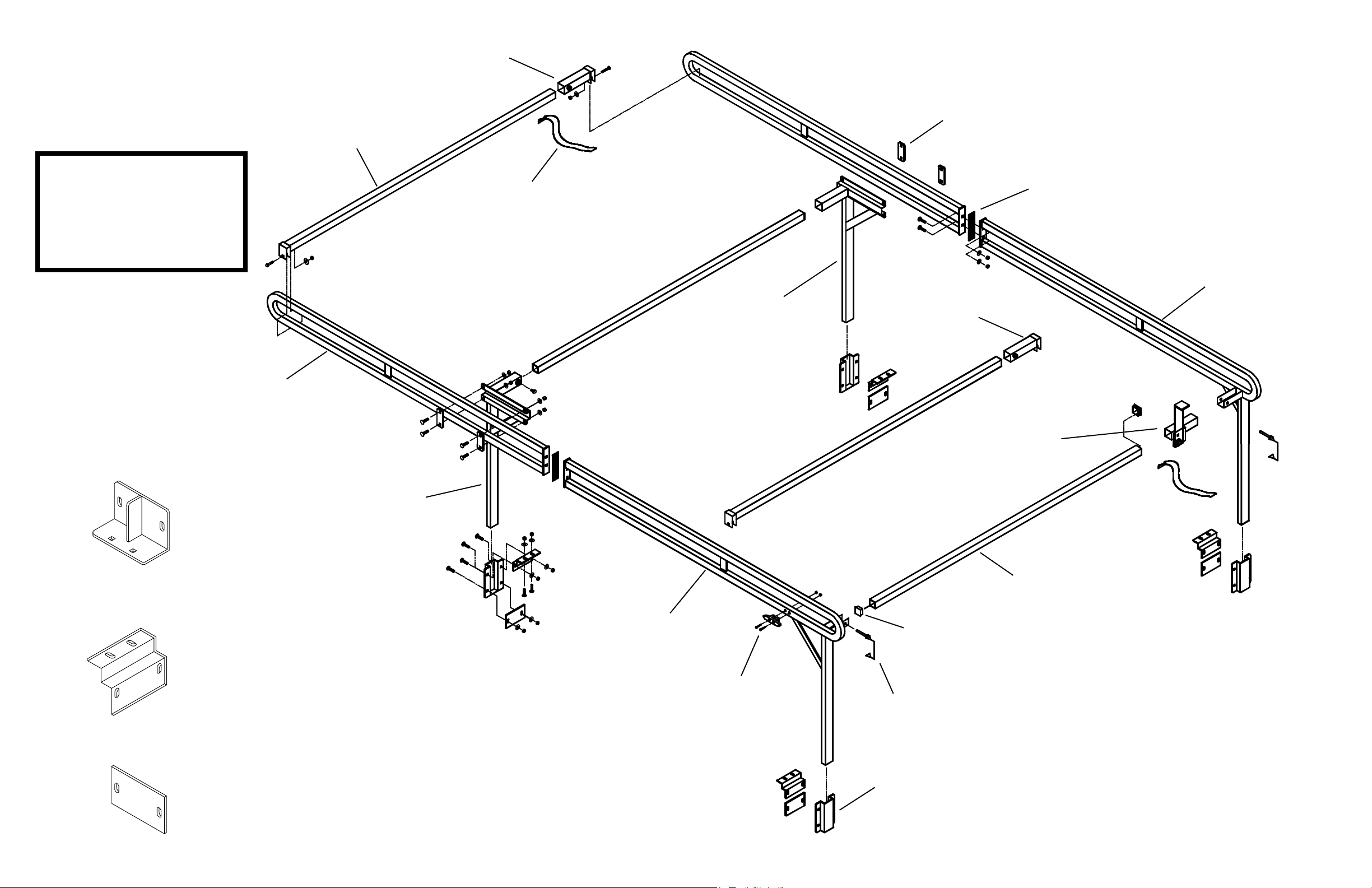
Crossmember (open one end)
(2)
Clamp Socket
(w/ loop for Strap)
(1)
Rail Clamp Plate (4)
NOTE: To prevent rust from occurring, touch-up any drilled holes.
NOTE: Apply E-6000 Sealant* to the
service body around drilled holes
prior to assembly.
* Included with your Rack
Rail Half
(2)
Use these illustrations to identify parts
Strap, 1450 (2)
Front Leg
Passenger Side (1)
Cushion Strip
(bulk)
Rear Leg/Rail
Passenger Side (1)
Clamp Socket (1)
Ladder Stop
Assembly (1)
Upper Bracket, 1225 (2)
Lower Bracket, 1225 (4)
Mounting Plate, 1225 (4)
Front Leg
Driver Side (1)
Rear Leg/Rail
Driver Side (1)
Crossmember (open ends) (2)
Square Cap Plug (2)
Rope Cleat (4)
Snapper Pin (2)
Leg Support (4)
Figure 1. Exploded View
2
Page 3
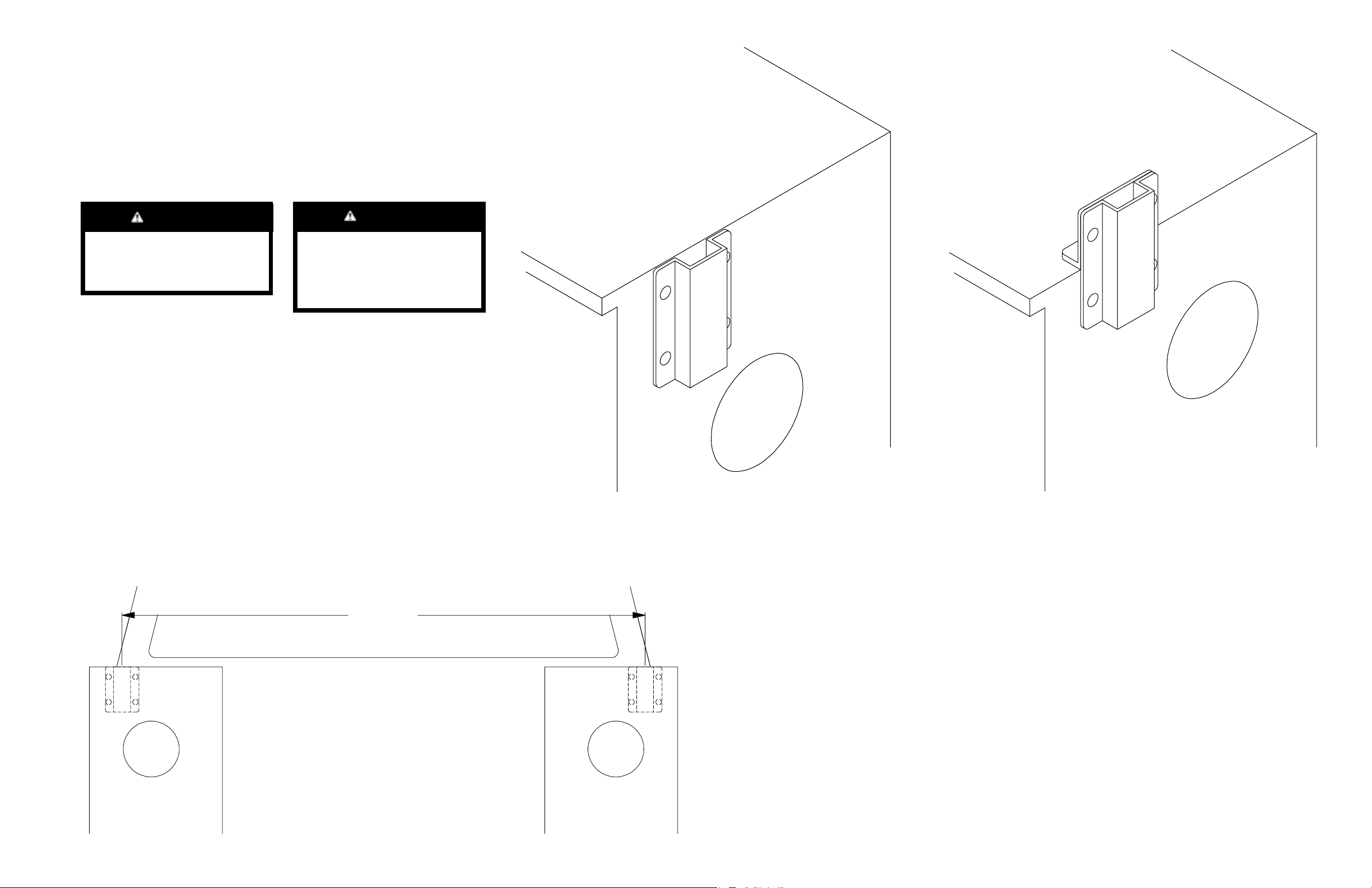
Rear Leg Support Installation - Begin with the rear of the vehicle, as
1.
the taillight location may determine the mounting option as well as the side to side
placement. The Leg Supports when mounted must not be more than 72 center to
center (see Figure 2.), and must be centered evenly side to side. Mount near the
outside corner of the box if possible, for strength. Option 1 is preferred (see Fig-
ure 3.), but Option 2 (see Figure 4.) may be necessary at the rear of vehicle, de-
pending on taillight locations. Decide which option to use, then follow that options
procedure. Fasten the Leg Support/Upper and Lower Brackets loosely at the rear
of the box.
CAUTION
Prior to drilling, so as not to
cut electric wires, etc., check
the vehicle for locations.
CAUTION
To keep debris out of your
eyes when drilling or sawing,
always wear protective
eyewear.
Figure 3. Option 1 Installed (viewed from Driver Side rear)
Figure 4. Option 2 Installed (viewed from Driver Side rear)
center
to
center
Figure 2. Center to Center Distance
(shown mounted per Option 1.)
3
Page 4

Option 1 Installation - Place a Lower Bracket at the top of the rear end
panel inside the service body, and in position side to side. Mark the centers of the
four obround holes (see Figure 5.). Remove the Lower Bracket, and using a
square, draw a line down 6 from the centers of the marks on the rear panel. Measure down 3-3/4 from the rear panel marks, and mark the lines. Drill the six marks
with a 7/32 drill bit. Re-drill the rear panel holes with a 7/16 drill bit. Re-drill the
top holes with a 1/2 drill bit. Repeat this procedure at the other side of the service
body. Loosely assemble a Leg Support, Lower Bracket and a Mounting Plate at
each rear location (see Figure 6.).
Seam/Flange
Knaphiede®
Service Body
only
Option 2 Installation (used only at the rear of the vehicle) -
Fasten together one Leg Support and one Upper Bracket (see Figure 7.). Place
the assembled Leg Support at the top of the end panel outside the service body,
and in position side to side. Mark the two square holes of the Leg Support and the
two of the Upper Bracket (see Figure 8.). Drill the marks with a 7/32 drill bit. Redrill the back panel holes with a 7/16 drill bit. Re-drill the top holes with a 1/2 drill
bit. Repeat this procedure at the rear on the other side of the service body.
Loosely assemble a Leg Support, Upper and Lower Bracket at each rear location
(see Figure 9.).
3/8-16 x 1-1/2
Carriage Bolt
tap this Carriage Bolt
into the 1/2 drilled hole
NOTE: Use caution when
drilling so as not to thrust
the drill bit into the cab of
the vehicle.
Figure 5. Lower Bracket - used for marking
service body top and rear end panel
Mark these holes
long leg of
Lower Bracket
Service
Body
Rear
Lower
Bracket
3/8 Flat
Washer
(6 places)
3/8-16 Nylon
Lock Nut
(6 places)
3/8-16 Nylon
Lock Nut
Leg Support
Leg Support
3/8 Flat
Washer
Figure 7. Leg Support/Upper Bracket Assembly for marking at rear
3/8-16 x 1-1/2
Carriage Bolt
(6 places)
Mounting
Plate
Figure 6. Option 1 Assembly
4
Figure 8. Assembled Leg Support - used for marking all rear mounting holes
Page 5

3/8-16 Nylon
Lock Nut
(6 places)
Lower
Bracket
Upper
Bracket
Leg Support
Leg Height - Measure from inside Leg Support to a minimum of at least 2
3.
above cab of truck (see Figure 11.). The Legs can be cut this dimension. NOTE: If
Leg Support mounting Option 2 was used at the rear, the Rear Legs will be
cut 3-7/8 shorter than the Front Legs to keep the rack level.
2 Min.
3/8 Flat
Washer
(6 places)
Figure 9. Option 2 Assembly
3/8-16 x 1-1/2
Carriage Bolt
(6 places)
2. Front Leg Support Installation - With the Leg Supports loosely
mounted at the rear, measure the distance from the inside of the service body to
the Lower Bracket (see Figure 10.). Use this dimension to position the Leg Support in the service body at the front. Repeat the marking, drilling and fastening procedure shown in Step 1, Option 1.
NOTE: Use caution when drilling so
as not to thrust the drill bit into
the cab of the vehicle
cut Leg height
Figure 11. Leg Height
4. Crossmembers - Measure center to center of the Leg Supports
(see Figure 12.). Cut all Crossmembers 1/2 less than this length.
center
to
center
Figure 10. Lower Bracket Distance
Figure 12. Crossmember Length
5
Page 6

5. Front Leg Crossmember - Install each Crossmember end into a Front
Leg Socket (see Figure 13.). Place the Leg/Crossmember assembly into the Leg
Supports at the front of the truck with the Leg gussets facing rearward. Tighten the
Leg Supports so the Legs are at 90 degrees to the service body. Fasten the
Crossmember in the Leg sockets.
6. Rail Fastening - Bolt the front Rail and Rear Leg/Rail Weldment halves to-
gether using two bolts per rail (see Figure 14. and detail Figure 15.).
3/8-16 x 1-1/4
Carriage Bolt
See Figure 15.
for detail
3/8 Flat Washer
- IMPORTANT This Leg gusset
must face rearward
at all times
Crossmember
(open ends)
Front Leg
(Passenger Side)
3/8-16 x 3/4 Hex
Head Thread
Cutting Bolt
(2 places)
Leg Support
Front Leg
(Driver Side)
Leg Support
3/8-16 x 1-1/4
Carriage Bolt
(2 places)
3/8-16 Nylon Lock Nut
Figure 14. Rail Fastening - Passenger Side only shown repeat this for other Rail halves
Rail Half
Cushion Strip
(cut from bulk)
Rear Leg/Rail
Figure 13. Leg/Crossmember to Leg Support Assembly
The Cushion Strip is not
pre-punched - push bolts
through the Cushion Strip
when assembling
3/8 Flat
Washer
(2 places)
Figure 15. Rail Fastening Detail
3/8-16 Nylon
Lock Nut
(2 places)
6
Page 7

7. Rear Leg / Rail Mounting - With
the help of another person, install the
Driver Side Rear Leg/Rail into the Leg
Support at the rear, and loosely assemble
the Rail assembly in the Front Leg rail
sockets (see Figure 16. and detail Figure
17.). Repeat this with the Passenger Side
Rear Leg/Rail. Tighten both of the Rear
Leg/Rails in the Leg Supports, making
sure the Legs are at 90 degrees to the service body. Tighten the Clamp Plates on the
front Rails.
See Figure 17.
for detail
Figure 16. Rear Leg/Rail Mounting
5/16 Flat
Washer
(4 places)
Leg Support
8. Rear Crossmember - Place the Crossmember in the sockets, center it,
then mark the socket holes. Remove the Crossmember and drill the marks with a
3/8" drill bit. Install the Black Plugs in the Crossmember, replace the Crossmember in the sockets and install the Snapper Pins (see Figure 18.).
Square
Cap Plug
3/8
Hole
Crossmember
(open both ends)
Snapper
Pin
Rear Leg/Rail
(Driver Side)
Figure 18. Rear Crossmember Detail - Driver Side only shown procedure is the same for Passenger Side
5/16-18 x 1
Carriage Bolt
(4 places)
Clamp
Plate
(2 places)
Front Leg
(Driver Side)
Rail
Socket
9. Ladder Stop - Remove rear Crossmember and slide Ladder Stop onto it.
Install Crossmember on rack. With a Ladder on the rack, locate the Ladder Stop
inside of the ladder and then secure. Insert a strap through the loop on the Ladder
Stop and on the front Crossmember Socket. Refer to the warning decal on the
Ladder Stop.
5/16-18 Nylon
Lock Nut
(4 places)
3/8-16 x 3/4"
Thread Cutting
Bolt
Strap
Rail Assembly
Figure 17. Rear Leg/Rail Mounting Detail - Driver Side only shown procedure is the same for Passenger Side
Figure 19. Ladder Stop Detail - Passenger Side only shown procedure is the same if deciding to install on the Driver Side
7
Page 8

10. Front and Middle Crossmember - Install one at the front
and one at the middle of the rack (see Figure 20.).
Rail
WARNING
WEATHER GUARD®
REFINISHING PROCEDURES
5/16-18 x 2
Carriage Bolt
(2 places)
Crossmember
Sleeve
Crossmember
(one open end)
5/16 Flat
Washer
(2 places)
5/16-18 Nylon
Lock Nut
(2 places)
Rail
Figure 20. Front and Middle Crossmember Assembly/Installation
(see Figure 1. for approximate placement on the rack)
3/8-16 x 3/4"
Thread
Cutting Bolt
(1 place)
Ladders must be secured per ANSI standard
A142.2-1990 paragraph 8.4.4. Ladder damage will
occur from road shock and vehicle vibration if the
ladder is not properly secured to the ladder rack.
Bouncing and side to side motion of an improperly
secured ladder will cause wear and weaken the
ladder. Using a damaged ladder could lead to a
structural collapse and could result in a serious
injury or death.
Bolt Chart
10-24 5/16-18 3/8-16
Nylon Lock Nuts
5/16 Flat
Washer
3/8 Flat
Washer
All Weather Guard® products are finished with a polyester powdered coating, and it is important to follow these
procedures to get proper adhesion. As
Weather Guard® cannot control the
finishing of the products, Weather
Guards® warranty on paint is not applicable on refinished products.
1. Sand the surface to be painted with
180-200 grit sand paper to rough up
the surface. This should be followed by
wet sanding with a 400 grit wet or dry
paper.
2. Wipe down the sanded surface with
ketone based thinner. This removes
the dust and softens the powder coating for better paint adhesion.
3. Wipe sanded area with a tack rag to
remove loose dust and particles before
painting.
NOTE: Do not use a lacquer over
the powdered coating.
10-24 Nylon
Lock Nut
11. Rope Cleats - Install the four
Rope Cleats where desired. Apply
E-6000 Sealant on the back of the
Rope Cleats and under the nuts before
installing (see Figure 21.).
E-6000
Sealant
Rope
Cleat
10-24 x 2-3/4 Screw
(2 places)
Figure 21. Rope Cleats - Illustration shows only one Rope Cleat - repeat this for the remaining three Rope Cleats
(see the cover page illustration for approximate placement)
7/32 Hole
(2 places)
(2 places)
E-6000
Sealant
5/16-18 x 1
Carriage Bolt
5/16-18 x 2
Carriage Bolt
3/8-16 x 1-1/2
Carriage Bolt
3/8-16 x 1-1/4
Carriage Bolt
10-24 x 2-3/4
Slotted Head
Screw
3/8-16 x 3/4
Thrd. Cutting
Bolt
- NOTICE -
Any modification or unintended use of this product shall immediately void all manufacturers warranties.
Manufacturer disclaims all liability for injuries to persons or property resulting from any modification to,
or unintended use of this product.
If you have any questions, please give us a call. Call Toll Free 1-800-456-7865
Weather Guard® products are protected by one or more of the following patents or trademarks:
U.S. - 842268, 1661625, 1663369; Canada - 1218968, 282725; U.K. - 1400720;
N.Z - 296049; AUS. - 761964; other patents pending.
12. Sealant - Seal all nuts, bolts,
and Crossmember to sleeve seams
with E-6000 Sealant.
WARRANTY WILL BE VOID IF
SEALANT IS NOT APPLIED TO
ALL SEAMS AND CREVICES
KNAACK LLC
420 E. TERRA COTTA AVENUE
CRYSTAL LAKE, ILLINOIS, 60014 - 815-459-6020
©2004 Knaack LLC
8
Part No. 24-0135 REV. D ECN 5315 05/13
 Loading...