

Page 1
- ATTENTION -
Read and understand all instructions and warnings before installing and using this
product. Confirm contents of the shipping carton with the "Parts Identification" page
before beginning installation. If a part is missing, or if you have any questions,
please call WEATHER GUARD customer service at 1-800-456-7865.
INSTALLATION MANUAL
MODEL 1210 150" ACCESSORY SIDE RAIL
MODEL 1211 132" ACCESSORY SIDE RAIL
Approximate Assembly and Installation Time:
60 min. (1 hr.) depending on truck equipment installation experience.
WARNING
This product is only intended for, and only safe for, transporting ladders, lumber,
pipe and other similar materials. It is the responsibility of the user to secure these
materials to the rack before transporting. Any modifications made to this product,
or use of this product for any other purpose than its intended use, could create a
hazardous condition that can cause serious personal injury or property damage.
Ladders must be secured per ANSI standard A142.2-1990 paragraph 8.4.4. Ladder
damage will occur from road shock and vehicle vibration if the ladder is not properly
secured to the ladder rack. Bouncing and side to side motion of a improperly
secured ladder will cause wear and weaken the ladder. Using a damaged ladder
could lead to a structural collapse and could result in a serious injury or death.
- NOTICE -
Any modification or unintended use of this product shall immediately void all
manufacturers warranties. Manufacturer disclaims all liability for injuries to persons
or property resulting from any modification to, or unintended use of this product.
Some vehicle manufacturers require a reinforcing kit, available through the vehicle
dealership, to be installed on the truck bed prior to mounting any kind of rack or tool
box. Contact your dealership to see if your vehicle requires a reinforcing kit before
installation.
CAUTION
Never load your rack to exceed the safe capacity of your vehicle. Heavy loads when
carried high can dangerously alter the center of gravity of your vehicle. Consult your
vehicle owners manual for specifications on load ratings and recommendations
from the vehicle manufacturer regarding installation of aftermarket racks and tool
boxes.
420 E. TERRA COTTA AVENUE, CRYSTAL LAKE, ILLINOIS, USA 60014
KNAACK MANUFACTURING COMPANY
815-459-6020, info@knaack.com
© 2003 Knaack Manufacturing Company
Part No. 24-0155 Rev. 11/03
This LIMITED WARRANTY is madebyKnaackManufacturingCompany, 420 E. TerraCottaAve.,Crystal
Lake,Illinois to theoriginalretailpurchaserof KNAACK
KNAACKMANUFACTURING COMPANY WARRANTS THAT KNAACKOR WEAT HER GUARD
EQUIPMENT WILL BE FREE FROM DEFECTS IN MATERIAL ANDWORKMANSHIP FOR A PERIOD OF
TWO (2)YEARS FROM DATE OF PURCHASE BY THE ORIGINAL RETAIL PURCHASER.
If, beforetheexpirationoftheWarrantyperiod,purchaserdiscoversthattheKNAACKor
WEATHER GUARD Equipmentfails to fulfill theWarranty, pur chasershall contactKnaackManufacturing
Companytomakearrangementsforaninspectionoftheproduct.If KnaackMfg.Co.determinesa
defectexists, KnaackMfg.Co.shall, atits optionandexpense,repairor replaceanydefectivepart.
All Warrantyrepairsshall bemadebyanauthorizedKNAACKEquipmentdealeror KnaackMfg.Co.
approvedservicecompany.
This Warrantyshall notapplyif theKNAACKor WEAT HER GUARDEquipmenthasbeensubjectedto
misuse, abnormalserviceor handling,impropermaintenance,or alterationsmadeby anyoneotherthan
aKNAACKor WEATHER GUARD Equipmentdealeror aKnaackMfg.Co.approvedservicecompany.
THE WARRANTY PRINTED ABOVE IS THE ONLY WARRANTY APPLICABLE TO THIS PURCHASE.
ALL OTHER WARRANTIES, EXPRESS OR IMPLIED, INCLUDING BUT NOT LIMITED TO THE IMPLIED
WARRANTIES OF MERCHANTABILITY AND FITNESS FOR APARTICULAR PURPOSE ARE HEREBY
DISCLAIMED.
KNAACKMANUFACTURING COMPANY SHALL NOT BE LIABLE FOR ANY INCIDENTAL OR
CONSEQUENTIAL DAMAGESARISING OUT OF ANY BREACH OF THIS WARRANTY. NOR SHALL
THE DAMAGESEXCEED THE RETURN AMOUNT OF THE PURCHASE PRICE PAID BY THE ORIGINAL
PURCHASER.
This Warrantyis in lieu ofall Warrantiesexpress or implied.The terms of this Warrantyshall notbe
modifiedbyanyparty,their successors or assigns. This Warrantygivesyouspecificlegalrights, and
youmayalso haveotherrights whichvaryfrom stateto state.
WEATHER GUARD® products are protected by one or more of the following patents or trademarks:
U.S. - 4509787, 842268, 1661625, 1663369, 2228051, 2434963; U.K. - 1400720; NZ - 296049;
Aus. - 761964; Canada - 1218968, 282725.
LIMITED WARRANTY
or WEATHER GUARD Equipmentproducts.
Page 1 of 6
Page 2
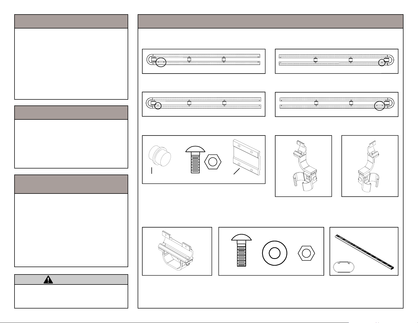
TOOLS REQUIRED
PART IDENTIFICATION & REPLACEMENT PART NUMBERS
3/8" Drive Ratchet
3/8" Drive Socket 1/2" Deep Well
3/8" Drive Socket 7/16"
5/16" Drill Bit
Electric Drill
Tape Measure
Hammer
Center Punch
3/8" Drive Torque Wrench (foot lbs.)
FIT-UP
Product fit-up is based on vehicle design available at the revision date of
this installation manual. The ATRTM has
been fitted and is recommended for
any combination of bed lengths and
cab designs on most pickup trucks.
IMPORTANT!
Model 1205 Owners.
If installing a Model 1211 on a Model
1205, compact size truck, the front accessory crossmember, Part X, will
have to be cut down to 57" from 67".
NOTE: Side rails are labeled in the packaging, take note before removing them from the carton. The rear assemblies have one predrilled hole and the front assemblies have two predrilled holes. The smooth edge faces
away from the truck and the grooved edge faces inward. All side rails have a replacement part number of #7619.
Two Holes
Part O (Qty. 1)
Driver Side Front Rail Assembly
One Hole
Part Q (Qty. 1)
Passenger Side Rear Rail Assembly
Part S
Side Rail Hardware Kit
Part S - Side Rail Alignment Plug (Qty. 4)
1/4-20 X 5/8" Carriage Bolt (Qty. 8)
1/4-20 Stop Nut (Qty. 8)
Part T - Side Rail Connecting Plate (Qty. 2)
Replacement Part Number #7620
Smooth Edge Up
Smooth Edge Up Smooth Edge Up
Part T
Smooth Edge Up
Part P (Qty. 1)
Driver Side Rear Rail Assembly
Part R (Qty. 1)
Passenger Side Front Rail Assembly
Part U (Qty. 1)
Driver Side
Rear Mounting Clamp
Replacement Part #7617
Part V (Qty. 1)
Passenger Side
Rear Mounting Clamp
Replacement Part #7636
One Hole
Two Holes
Carefully pry off the end red cap and
trim the black anti-wear strip back 10".
Cut 10" off the end of the cross member. Using an industrial adhesive, reapply the red end cap.
CAUTION
To keep debris out of your eyes
when drilling or cutting, always wear
protective eye wear.
Page 2 of 6
Part W (Qty. 4)
Universal Driver/Passenger
Front Mounting Clamp
Replacement Part #7618
Rail Mounting Hardware Kit
1/4-20 X 3/4" Carriage Bolt (Qty. 10)
1/4-20 Stop Nut (Qty. 10)
1/4" Flat Washer (Qty. 10)
Replacement Part Number #7621
Cross
Section
Part X (Qty. 1)
Front / Accessory
Cross Member
Replacement Part #1215
Page 3

STEP
ONE
Working on level ground insert two side
rail alignment plugs, Part S, into the driver
side front rail assembly, Part O. Connect
front driver side rail assembly, Part O, and
driver side rear rail assembly, Part P, using side rail connector plate, Part T, 1/4 20 X 5/8" carriage bolts and 1/4-20 stop
nuts.
STEP
TWO
1/4-20
Stop Nuts
PART S
PART T
1/4-20 X 5/8"
Carriage Bolts
PART R
PART O
PART Q
Working on level ground insert two side
rail alignment plugs, Part S, into the passenger side front rail assembly, Part R.
Connect front passenger side rail assembly, Part R, and passenger side rear rail
assembly, Part Q, using side rail connector plate, Part T and 1/4 -20 X 5/8" carriage bolts and 1/4" stop nuts.
IMPORTANT!
Do not overtighten 1/4" fasteners.
Groove edge faces in
towards the truck bed.
PART P
Smooth edge faces away
from the truck bed.
Page 3 of 6
Page 4

STEP
THREE
Slide the universal front mounting clamps,
Part W, onto both the driver and passenger side of the installed front cross member from the Model 1200 or Model 1205.
Leaving 1/4" gap (see diagram) between
the clamps and legs. Tighten the 5/16"
hardware to 15 foot pounds of torque.
Front View
PART W
1/4" Gap
Rear View
5/16-18 X 3"
Carriage Bolt
PART V- Passenger
Side
Not Shown
PART U- Drivers
Side
STEP
FOUR
Separate the mounting clamps by removing the 5/16-18 X 3" carriage bolt from the
drivers side rear mounting clamp, Part U,
and the passenger side rear mounting
clamp, Part V.
Install the mounting clamps around the rear
legs. Leaving a 1/4" gap (see diagram) between the clamps and cross member. Reinstall the 5/16-18 carriage bolts and
tighten to 15 foot pounds of torque. The
solid side of the clamps must face towards
the rear of the vehicle.
Page 4 of 6
STEP THREE
1/4" Gap
STEP FOUR
Page 5

STEP
FIVE
Place driver side rail assembly, from Step
One, into the driver side rear mounting
clamp. Fasten together using the predrilled hole in the side rail and a 1/4-20 X
3/4" carriage bolt and 1/4-20 stop nut, from
the rail mounting hardware kit. Repeat the
process for the passenger side rail.
STEP SIX
1/4-20 Stop Nuts
1/4" Flat Washers
1/4-20 X 3/4"
Carriage Bolts
1/4-20 Stop Nut
1/4" Flat Washer
1/4-20 X 3/4"
Carriage Bolt
Using a center punch, mark the holes to
be drilled through the square holes on the
front mounting clamp. Remove the side
rails from the vehicle and drill the holes using a 5/16" drill bit. Fasten the side rails to
the mounting clamps using the 1/4-20 X
3/4" carriage bolts, 1/4" washers, and 1/420 stop nuts, from the rail mounting hardware kit.
IMPORTANT!
Do not overtighten 1/4" fasteners.
CAUTION
To keep debris out of your eyes when
drilling, always wear protective eye wear.
Page 5 of 6
Page 6

STEP
SEVEN
Using the predrilled holes on the drivers
side rail install the universal front side rail
mounting clamp, Part W, using the 1/4-20
X 3/4" carriage bolts, 1/4" washers, and
1/4-20 stop nuts, from the rail mounting
hardware kit. Repeat the process for the
passenger side rail.
IMPORTANT!
Do not overtighten 1/4" fasteners.
1/4-20 Stop Nuts
1/4" Flat Washers
PART W
PART X
1/4-20 X 3/4"
Carriage Bolts
Installation is
now complete.
STEP EIGHT
Insert the front cross member, Part X, into
the front rail mounting clamps, Part W, installed in Step Seven. Adjust cross member to allow equal distance on both sides.
Tighten the mounting clamps to the cross
member using the 5/16-18 hardware preinstalled on the mounting clamp to 15 foot
pounds of torque.
Model 1205 owners please read note
on bottom left hand corner of page 2.
Page 6 of 6
IMPORTANT!
Before operating vehicle check to ensure the 5/16" fasteners are set to a torque
rating of 15 foot pounds. 1/4" fasteners should be snug. DO NOT OVERTIGHTEN
1/4" FASTENERS.
At the end of the first week of use check all fasteners for proper tightness and then
every three months there after.
ONLY OPERATE VEHICLE WITH
REAR CROSS MEMBER IN PLACE
DO NOT OPERATE VEHICLE WITH
REAR CROSS MEMBER REMOVED
 Loading...