

Page 1
INSTALLATION MANUAL
MODEL 1200 FULL SIZE TRUCK
MODEL 1205 COMPACT SIZE TRUCK
- ATTENTION -
Read and understand all instructions and warnings before installing and using this
product. Confirm contents of the shipping carton with the "Parts Identification" page
before beginning installation. If a part is missing, or if you have any questions,
please call WEATHER GUARD
® customer service at 1-800-456-7865.
WARNING
This product is only intended for, and only safe for, transporting ladders, lumber,
pipe and other similar materials. It is the responsibility of the user to secure these
materials to the rack before transporting. Any modifications made to this product,
or use of this product for any other purpose than its intended use, could create a
hazardous condition that can cause serious personal injury or property damage.
Ladders must be secured per ANSI standard A142.2-1990 paragraph 8.4.4. Ladder
damage will occur from road shock and vehicle vibration if the ladder is not properly
secured to the ladder rack. Bouncing and side to side motion of a improperly
secured ladder will cause wear and weaken the ladder. Using a damaged ladder
could lead to a structural collapse and could result in a serious injury or death.
- NOTICE -
Any modification or unintended use of this product shall immediately void all
manufacturers warranties. Manufacturer disclaims all liability for injuries to persons
or property resulting from any modification to, or unintended use of this product.
Some vehicle manufacturers require a reinforcing kit, available through the vehicle
dealership, to be installed on the truck bed prior to mounting any kind of rack or tool
box. Contact your dealership to see if your vehicle requires a reinforcing kit before
installation.
Load capacity: Up to 800 lbs. evenly distributed.
Approximate Assembly and Installation Time:
60 min. (1 hr.) depending on truck equipment installation experience.
This LIMITED WARRANTY is madebyKnaackManufacturingCompany, 420 E. TerraCottaAve.,Crystal
Lake,Illinois to theoriginalretailpurchaserofKNAACK
KNAACKMANUFACTURING COMPANY WARRANTS THAT KNAACKOR WEATHER GUARD
EQUIPMENT WILL BE FREE FROM DEFECTS IN MATERIAL AND WORKMANSHIP FOR A PERIOD OF
TWO (2)YEARS FROM DATE OF PURCHASE BY THE ORIGINAL RE TAIL PURCHASER.
If, beforetheexpirationoftheWarrantyperiod,purchaserdiscoversthattheKNAACKor
WEATHER GUARDEquipmentfails to fulfill theWarranty, purchasershall contactKnaackManufacturing
Companytomakearrangementsfor aninspectionof theproduct. If KnaackMfg.Co.determinesa
defectexists, KnaackMfg.Co.shall, atits optionandexpense,repairor replaceanydefectivepart.
All Warrantyrepairsshall bemadebyan authorizedKNAACKEquipmentdealeror KnaackMfg.Co.
approvedservicecompany.
This Warrantyshall notapplyif theKNAACK or WEATHER GUARD Equipmenthasbeensubjectedto
misuse, abnormalserviceor handling,impropermaintenance,or alterationsmadeby anyoneotherthan
aKNAACKor WEAT HER GUARD Equipmentdealeror aKnaackMfg.Co.approvedservicecompany.
THE WARRANTY PRINTED ABOVE IS THE ONLY WARRANTY APPLICABLE TO THIS PURCHASE.
ALL OTHER WARRANTIES, EXPRESS ORIMPLIED, INCLUDING BUT NOT LIMITED TO THE IMPLIED
WARRANTIES OF MERCHANTABILITY ANDFITNESS FOR A PARTICULAR PURPOSE ARE HEREBY
DISCLAIMED.
KNAACKMANUFACTURING COMPANY SHALL NOT BE LIABLE FOR ANY INCIDENTAL OR
CONSEQUENTIAL DAMAGESARISING OUT OF ANY BREACH OF THIS WARRANTY. NOR SHALL
THE DAMAGESEXCEED THE RETURN AMOUNT OF THE PURCHASE PRICE PAID BY THE ORIGINAL
PURCHASER.
This Warrantyis in lieu of all Warrantiesexpress or implied.The terms of this Warrantyshallnotbe
modifiedby anyparty, their successors or assigns. This Warrantygives youspecificlegalrights, and
youmayalso haveotherrights whichvaryfromstatetostate.
LIMITED WARRANTY
or WEATHER GUARD Equipmentproducts.
CAUTION
Never load your rack to exceed the safe capacity of your vehicle. Heavy loads when
carried high can dangerously alter the center of gravity of your vehicle. Consult your
vehicle owners manual for specifications on load ratings and recommendations
from the vehicle manufacturer regarding installation of aftermarket racks and tool
boxes.
420 E. TERRA COTTA AVENUE, CRYSTAL LAKE, ILLINOIS, USA 60014
KNAACK MANUFACTURING COMPANY
815-459-6020, info@knaack.com
© 2003 Knaack Manufacturing Company
Part No. 24-0154 Rev. 11/03
BED LINER NOTE
The Model 1200 and 1205 are design to be installed on a truck bed without a
traditional plastic bed liner. Installation is possible with minimal trimming with
an under-the-rail plastic bed liner. Excessive trimming will be required with an
over-the-rail plastic bed liner. Spray-On bed liners do not interfere with the installation of the Model 1200 or 1205.
WEATHER GUARD® products are protected by one or more of the following patents or trademarks:
U.S. - 4509787, 842268, 1661625, 1663369, 2228051, 2434963; U.K. - 1400720; NZ - 296049;
Aus. - 761964; Canada - 1218968, 282725.
Page 1 of 8
Page 2
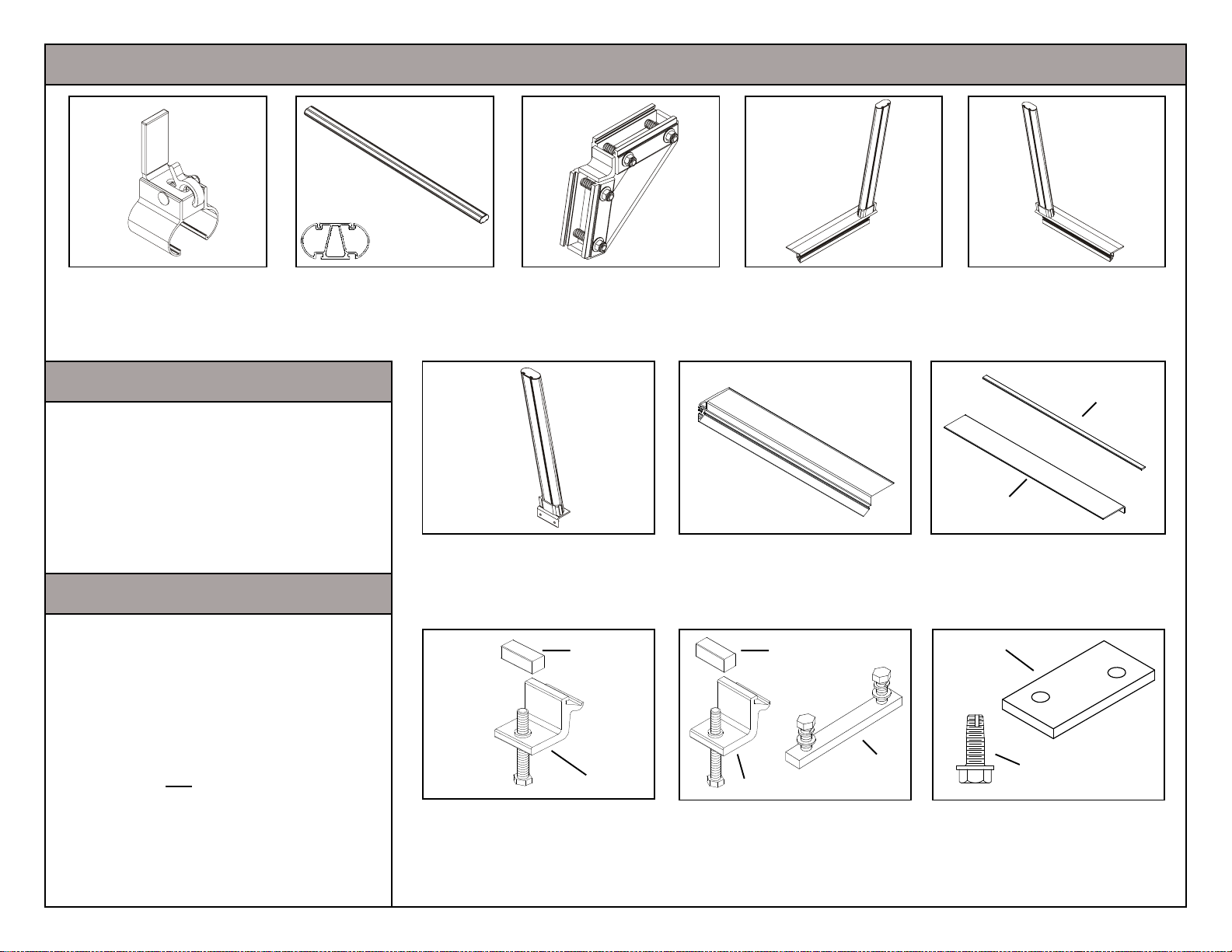
PART IDENTIFICATION & REPLACEMENT PART NUMBERS
Cross
Section
Part A (Qty. 4)
Universal
Ladder Stop
Replacement Part #7611
Part B (Qty. 2)
Cross Member
Replacement Part #7608
TOOLS REQUIRED
3/8" Drive Ratchet
3/8" Drive Socket 1/2" Deep Well
3/8" Drive Socket 9/16"
3/8" Drive Torque Wrench (foot lbs.)
Utility Knife
Masking Tape
Tape Measure
FIT-UP
Product fit-up is based on vehicle design
available at the revision date of this installation manual. The ATR
TM
is designed for a variety of bed lengths and
cab designs on most pickup trucks.
Part C (Qty. 4)
Universal
Triangle Bracket
Replacement Part #7622
Part F (Qty. 2)
Universal
Rear Leg
Replacement Part #7610
Part K
Part D (Qty. 1)
Driver Side
Front Leg
Replacement Part #7605
Part G (Qty. 2)
Universal
Rear Mounting Rail
Replacement Part #7607
Part K
Part E (Qty. 1)
Passenger Side
Front Leg
Replacement Part #7606
Part I
Part H
Mounting Pad & Wedge Kit
Part H - Mounting Pad (Qty. 4)
Part I - Mounting Wedge (Qty. 2)
Replacement Part #7609
Part M
The ATR
TM
is not recommended on the
following vehicles:
GMC Sonoma Crew Cab 4.5 Bed
Chevy S-10 Crew Cab 4.5 Bed
Toyota Tacoma
Page 2 of 8
Part J
Front Assembly Hardware Kit
Part J - Clamp Assembly (Qty. 4)
Part K - Clamp Block (Qty. 4)
Replacement Part #7612
Part L
Part J
Rear Assembly Hardware Kit
Part J - Clamp Assembly (Qty. 4)
Part K - Clamp Block (Qty. 4)
Part L - Mounting Bar (Qty. 2)
Replacement Part Number #7615
Part N
Tool Box Mounting Kit (May not use)
Part M - Shim (Qty. 4)
Part N - 5/16-18 x 3/4"
Self Tapping Bolt (Qty. 4)
Replacement Part #7616
Page 3
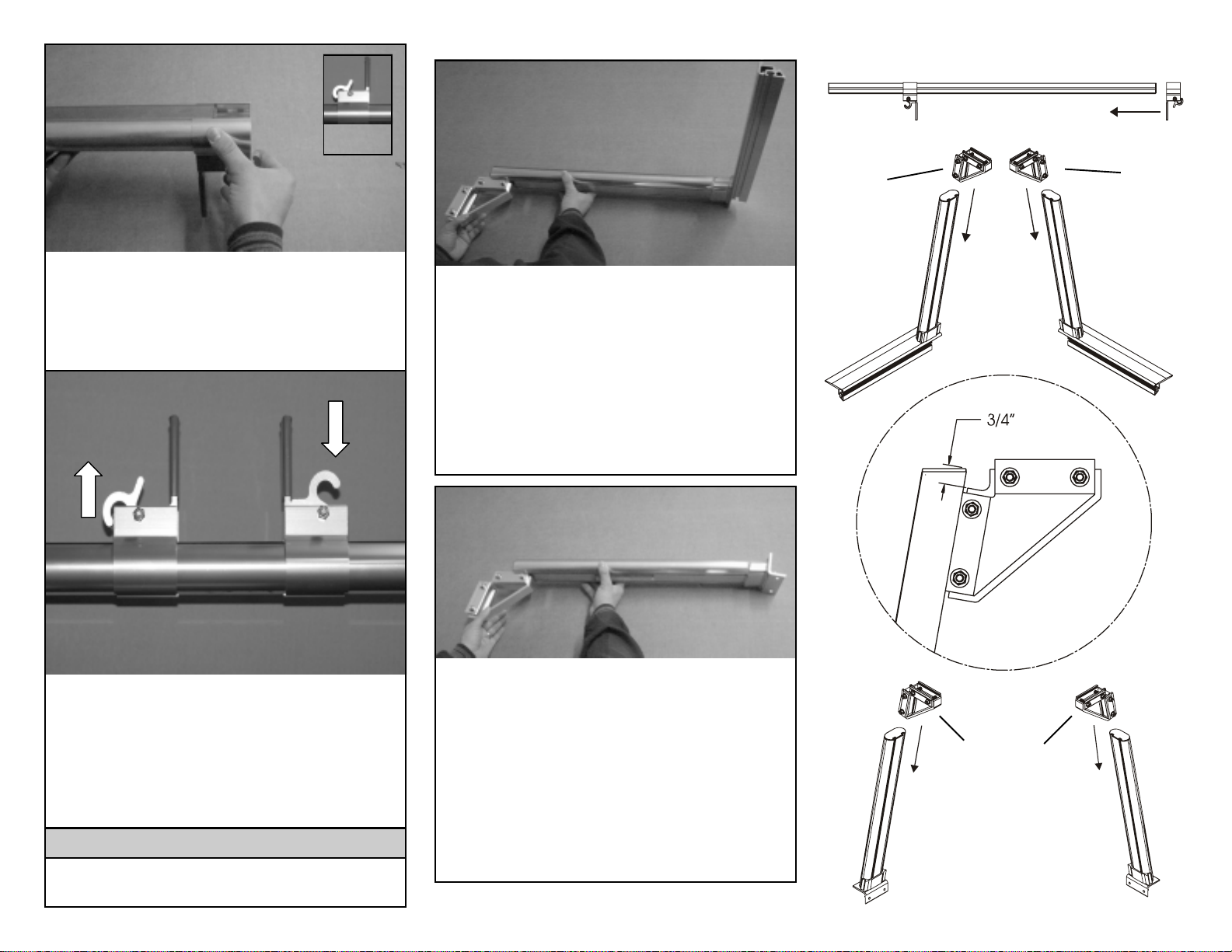
STEP ONE
STEP
PART B
Unlocked
Position
Holding the ladder stops, Part A, upside
down and in the unlocked position, slide
them onto each end of the cross member,
Part B. Repeat the process for the other
cross member.
STEP TWO
To Lock
To Unlock
THREE
Slide the triangle brackets, Part C, into the
driver side front leg, Part D, and passenger side front leg, Part E, from the top.
The 5/16-18 nuts are to face towards the
rail side of the leg. Using the triangle dimension diagram to the right as a guide,
position the triangle brackets 3/4" from the
top of the leg. Tighten the 5/16-18 fasteners to 15 foot pounds of torque.
STEP FOUR
PART A
5/16-18
PART C
Nuts
Face
towards
rail side
PART D PART E
Rail Side
PART C
5/16-18
Nuts
Face
towards
rail side
Rail Side
Unlocked
Position
Locked
Position
The ladder stops are designed to slide the
entire length of the cross member. Once
in the desired location, lock ladder stops
in place by lifting up on the lever. To unlock, push down on the lever. For purpose
of installation position them two feet from
either end.
IMPORTANT!
Do not operate vehicle with ladder
stops in the unlocked position.
Slide the triangle brackets, Part C, into
each of the universal rear legs, Part F, from
the top. Create a driver side and passenger side rear leg by facing the 5/16-18 nuts
one direction on a leg and the other direction on the other. Using the triangle dimension diagram to the right as a guide,
position the triangle brackets 3/4" from the
top of the leg. Tighten the 5/16-18 fasteners to 15 foot pounds of torque.
PART C
PART F
Drivers
Side
Triangle
Dimension
Diagram
PART C
5/16-18 nuts
face in one
direction
PART F
Passenger
Side
Page 3 of 8
Page 4

STEP
FIVE
Work on level
ground.
Place the cross member assembly, Part B,
on its side with the WEATHER GUARD
Product logo facing down. Insert the driver
and passenger side front leg assemblies,
Parts D & E, into the cross member assembly by sliding them in from both ends.
®
PART F
PART B
PART D
PART B
PART E
Now place the second cross member assembly, Part B, on its side with the
WEATHER GUARD
® Product logo facing
up. Insert the two universal rear leg assemblies, Part F, with the 5/16-18 nuts facing
up, into the cross member assembly by
sliding them in from both ends.
STEP SIX
Work on level
ground.
Using a torque wrench tighten the 5/16-18
fasteners to 15 foot pounds at the dimension shown in the chart to the right. Column A is for the front assembly and
column B is for the rear assembly.
Page 4 of 8
PART F
REAR ASSEMBLY
ATR MODEL1200
FULLSIZE TRUCKS
VEHICLE DIMENSION CHART
All GM Sierra/Chevy Silverado Trucks 5.50" 6.25"
All Dodge Ram Trucks 4.75" 6.25"
All Ford F-150 (2003 & 2004) Trucks 6.25" 6.00"
All Ford F-250 & F350 Trucks 5.00" 5.50"
Toyota Tundra 8’ Bed 6.50" 6.50"
Toyota Tundra 6.25" Bed 6.75" 6.75"
ATR MODEL 1205
CO MPACT SIZE TRUCKS
VEHICLE DIMENSION CHART
All GM Sonoma/Chevy S-10 Trucks 3.00" 6.25"
All Dodge Dokota Trucks 2.75" 2.75"
All Ford Ranger Trucks 4.25" 4.50"
DIMENSION A
FRO N T
ASSEMBLY
DIMENSION A
FRO NT
ASSEMBLY
DIMENSION A
REAR
ASS EMB LY
DIM ENSION A
REAR
ASSEMBLY
FRONT ASSEMBLY
"A"
Both ends of cross
member
NOTE: If your vehicle is not
shown in the chart, adjust the
rack on the ground and test fit it
on the truck bed until you reach
a snug fit between the bed
rails.
Page 5

STEP
SEVEN
1/8"
Place mounting pads, Part H, on top of
the truck bed rails. Cut the notch into the
mounting pad. Place the front assembly,
from Step Six, onto the truck with the
notched ends approximately 1/8" from the
front of the truck bed.
NOTE: Some truck beds will not allow
the notch to travel all the way forward.
STEP
EIGHT
Place clamp block, Part K, on the
threaded end of the clamp assembly,
Part J. The clamp block has an offset
hole. The thick side should face in towards the clamp. Use the thin side if
extra clearance is needed.
PART H
PART K
STEP NINE
Sliding the clamp assembly, Part J, into
the front assembly, place them as far away
from each other and as close to the ends
of the mounting rails as possible. Clamps
can not be more than 9.5" from either end
of the mounting rail. Clamp blocks, Part
K, are to be flush with the steel underside
of the bed rail. Using a torque wrench,
tighten the 3/8-16 fasteners in the clamp
assembly to 10 foot pounds.
PART J
IMPORTANT!
Clamps can not be
more than 9.5" from
either end of the
mounting rail.
STEP NINE NOTE: For Ford F250/
350 and some Dodge Dakota vehicles
place the front assembly 3" from front
of truck bed. Hold the clamp assembly, Part J, in place and slide the
mounting rail into the clamp until it is
1/8" from the front of the truck.
Page 5 of 8
Page 6

Mounting Wedge Location
Must be level
on both axis.
STEP TEN
With the tailgate closed place the
mounting pads, Part H, on top of the truck
bed rails. Tape in place the mounting
wedge, Part I, on top of the mounting pad
using the diagram to the right as a guide.
Set the rear mounting rail, Part G, on top
of the wedge and pad 1/8" from the closed
tail gate.
Wedge locations are
approximate. Make
All Chevy/GM
Dodge Ram
Ford F150 2003
Ford Ranger
Ford 250 / 350
No Wedge Necessary for the following vehicles:
Ford 150 2004 Toyota Tundra
Dodge Dakota
adjustments to ensure mounting rail,
Part G, is level on
both axis when
clamped to top of bed
rail.
Must be level
on both axis.
PART K
PART J
PART G
PART I
PART H
IMPORTANT!
Clamps can not be
more than 9.5" from
either end of the
mounting rail.
STEP
ELEVEN
Sliding the assembly clamps, Part J, into
the rear mounting rail, Part G, place them
as far away from each other and as close
to the ends of the mounting rails as possible. Clamps can not be more than 9.5"
from the ends of the mounting rails.
Clamp blocks, Part K, are to be flush with
the steel underside of the bed rail. Using a
torque wrench, tighten the 3/8-16 fasteners in the clamps to 10 foot pounds.
Page 6 of 8
Close Tailgate
for Steps 6 & 7
Page 7

STEP
TWELVE
PART L
IMPORTANT!
Before operating vehicle check to ensure the 3/8" bolts in the clamp assembly, Part J, are set to a torque
rating of 10 foot pounds and all the
5/16" fasteners are set to a torque rating of 15 foot pounds.
Disassemble the mounting bar, Part L, from
the rear assembly hardware kit and reassemble on the rear leg assembly, from Step
Six. Repeat process for other rear leg.
STEP
THIRTEEN
With the tailgate open, slide the rear cross
member assembly, from Step Six, into the
mounting rail channels with the logo facing
towards the rear. The driver side and passenger side need to slide into the mounting rail at the same time in order to avoid
binding. Legs can be placed at any location along the mounting rail. Using a
torque wrench, tighten the four 5/16" hex
head bolts to 15 foot pounds.
At the end of the first week of use
check all fasteners for proper tightness and then every three months
there after.
now complete.
ONLY OPERATE VEHICLE WITH OR WITHOUT
ENTIRE REAR CROSS MEMBER ASSEMBLY.
Installation is
DO NOT OPERATE VEHICLE
WITH OUT THE REAR
CROSS MEMBER
NOTE: Due to the taper of some truck
beds, it may be necessary to shorten the
distance between the legs as you slide the
assembly towards the front of the vehicle.
Page 7 of 8
Page 8

Tool Box Mounting Procedure
If a bed rail mounted tool box is to be installed with the Model 1200 or 1205, use
the 1/4" thick shims, Part M, that are provided in the tool box mounting hardware
TM
kit (came with the ATR
) a lon g wi th the
"J" bolts (supplied with the tool box). This
will insure a level mounting of the tool box
on the truck bed rails.
Where the mounting rails (Parts D, E, & F)
obstruct the use of a "J" Bolt, use a 5/1618 x 3/4" self-tapping bolt, Part N, in its
place which is supplied in the tool box
mounting hardware kit that came with the
TM
ATR
.
Place the tool box in the desired location
on the truck and trace the mounting slot in
the bottom of the tool box directly onto the
mounting rail.
Drill 1/4" Dia. Hole
3/4"
Part N
5/16-18 x 3/4"
Self Tapping Bolt
Ladder Rack
Fasteners
Supplied
with Box
Move the tool box out of the way and drill a
1/4" dia. hole 3/4" from the inside edge of
the mounting rail. (See diagram)
Reset the tool box in the desired position
and install the 5/16-18 x 3/4" self tapping
bolt and fender washer. The fender
washer came with the "J" bolts. If needed,
use the 1/4" shims, Part M, to level the tool
box on the truck.
IMPORTANT!
Do not overtighten the
self-tapping bolts.
Page 8 of 8
See Drilling Detail Above
Part M
1/4" Shim
Shim Pad
(Cut from the
tool box
mounting pad)
"J" Bolt
Supplied
with Box
 Loading...