

Page 1
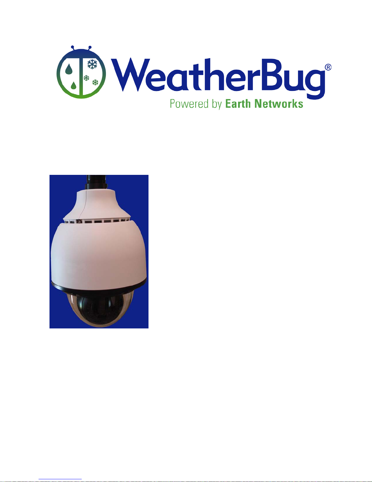
High Definition
Motion Camera
System Installation,
Release 1, Version 1.0
Operation, and
Maintenance Manual
February 2011
Page 2

HD MotionCam Installation Manual
Copyright
Copyright 2011, by AWS Convergence Technologies, Inc.
All Rights Reserved.
Manual Copyright, 2011, by AWS Convergence Technologies, Inc.
All Rights Reserved.
Information in this document is subject to change without notice and does not represent a
commitment on the part of AWS Convergence Technologies, Inc.
FCC Compliance
This equipment has been tested and found to comply with the limits for a Class A digital
device, pursuant to Part 15 of the FCC Rules. These limits are designed to provide
reasonable protection against harmful interference when the equipment is operated in a
commercial environment. This equipment generates, uses, and can radiate radio
frequency energy, and, if not installed and used in accordance with the instruction
manual, may cause harmful interference to radio communications. Operation of this
equipment in a residential area is likely to cause harmful interference in which case the
user will be required to correct the interference at his, or her, own expense.
Release 1, Version 1.0 -2- February 2011
Page 3
HD MotionCam Installation Manual
Disclaimer
The procedures, methods, and hardware described in this manual are intended to provide
general guidelines and instructions for installing the WeatherBug High Definition Motion
Camera (HD MotionCam) system. Each installation site is unique and each site may
require special considerations that are beyond the scope of this manual. Any questions
not covered within this manual should be directed to WeatherBug Weather Station
Technical Support at (800)624-4205 or email [email protected].
All procedures, methods, and hardware used to install a WeatherBug HD MotionCam
system must conform to all applicable building codes (national, state, and local).
Installation subcontractors are responsible for complying with all applicable codes.
Buyer and/or installer provided hardware must be equivalent or better (according to
industry standards) than that specified in the WeatherBug Installation Manual.
The buyer/installer is responsible for any damage caused by installation of the
WeatherBug HD MotionCam.
THINK SAFETY FIRST!
Warranty. The Seller warrants the hardware purchased by the Buyer against defects in
workmanship and materials for a period of one (1) year from date of delivery under this
contract. The Seller shall, at its sole option, either repair or replace defective items.
Buyer is responsible to return of defective items to Seller by means specified by the
Seller. The Buyer shall bear all shipping expenses. Packing of defective items for
return is responsibility of Buyer. Damage due to natural causes (storms, lightning,
flying debris, etc.) is not covered by this warranty. Damage resulting from Buyer
negligence or mishandling of hardware and software is not covered by this warranty.
Release 1, Version 1.0 -3- February 2011
Page 4

HD MotionCam Installation Manual
Table of Contents
Copyright ............................................................................................................................ 2
Disclaimer ........................................................................................................................... 3
Table of Contents ................................................................................................................ 4
Thank You! .......................................................................................................................... 5
Plan Ahead .......................................................................................................................... 5
Safety! ................................................................................................................................. 6
Getting Started .................................................................................................................... 7
Camera System Parts ...................................................................................................... 7
Tools Needed .................................................................................................................. 9
Site Evaluation .............................................................................................................. 10
Installation ........................................................................................................................ 11
Indoor Preliminary Setup .............................................................................................. 11
Viewing Live Video and Captured Images ................................................................... 13
Live Video ................................................................................................................. 13
Captured Images ....................................................................................................... 16
Routing the Cable ......................................................................................................... 17
Outdoor Installation ...................................................................................................... 18
Indoor connections ........................................................................................................ 21
Setting a Static IP Address for the HD MotionCam ......................................................... 22
Troubleshooting ................................................................................................................ 25
Maintenance ...................................................................................................................... 26
Additional Information...................................................................................................... 27
Specifications .................................................................................................................... 28
Release 1, Version 1.0 -4- February 2011
Page 5

HD MotionCam Installation Manual
Thank You!
Thank you and congratulations on acquiring the WeatherBug HD MotionCam system.
The WeatherBug HD MotionCam captures images of local weather conditions with the
advantage of a much higher resolution and the flexibility of changing viewpoints as often
as desired. The quality of the images from the WeatherBug HD MotionCam is sure to
enhance your weather system.
By installing and operating the entire WeatherBug system, you become an essential part
of the WeatherBug program, an integrated network of weather stations comprising the
largest weather monitoring system in the world.
You can monitor a high-quality, live image from the camera using a computer connected
to a Local Area Network (LAN). The frame rate is 30 frames per second (FPS).
Captured images are also available through the internet at www.weatherbug.com.
Plan Ahead
Read this entire manual before beginning installation. The WeatherBug HD MotionCam
installation can be straightforward and easy to complete if all steps are followed closely.
In order to ensure the most efficient installation possible, you MUST follow the steps
in “Indoor Preliminary Setup” BEFORE installing ANY equipment outdoors.
The most important aspect of preparation is safety. Installation of the HD
MotionCam requires working with electrical cable, drilling through walls or other dense
support structures, standing on ladders, and possibly, walking on roofs. Please carefully
read the following section on “Safety.”
Please pay close attention to the section on “Site Evaluation.” A complete site evaluation
determines proper placement of the camera and will prevent the need to have to re-mount
the camera and re-route the cables.
All additional parts needed (such as ladders, drills, bits, etc.) should be assembled and
inspected before beginning installation. WeatherBug cannot accept responsibility for
damage caused by these tools so all safety precautions should be adhered to. This would
include the use of leather gloves and goggles when appropriate.
If there are any questions, doubts, or discrepancies, call WeatherBug Weather Station
Technical Support at 800-624-4205 or email [email protected].
Release 1, Version 1.0 -5- February 2011
Page 6

HD MotionCam Installation Manual
Safety!
Only qualified personnel should install the HD MotionCam.
While installation of the HD MotionCam is not particularly difficult, it does usually
require installation near the rooftop and working with electrical wiring, which presents
some amount of risk.
To limit risk to self and property, this manual should be thoroughly read and understood
before beginning installation. Adhere to all warnings on the unit and in the operating
instructions.
Installation must conform to national, state, and local building code requirements with the
most stringent guidelines being adhered to.
The HD MotionCam should only be installed by someone comfortable with being on a
high ladder or rooftop and who is authorized by the site to perform the installation. Roof
and ladder safety is crucial!
Allow only qualified Electricians to make electrical connections. Take all reasonable
safety precautions – double checking a power cable connection could save a life.
Stay as far away from other electrical wiring as possible. Never allow the camera
housing, the cabling, a drill bit, or any other item to contact electrical wires or
conduit. Injury or death could result.
A qualified installer will need to securely mount the unit to a supporting structure capable
of sustaining the weight of the unit (approximately 16 pounds) by using appropriate tools
and hardware. Failure to properly secure the HD MotionCam could result in the unit
separating from the support structure and falling. This would not only damage the
camera, but could injure anyone standing nearby.
If needed, WeatherBug may be able to recommend professional installers and an estimate
of the cost. If this is desired, please call WeatherBug Weather Station Technical Support
at 800-624-4205 or email [email protected].
Release 1, Version 1.0 -6- February 2011
Page 7
HD MotionCam Installation Manual
Getting Started
Camera System Parts
Item Part Number
HD MotionCam in Housing 5500
Camera Support with Clamp for Mounting Arm Included in 5500
Connector for Camera and Mounting Arm Included in 5500
3 Rubber Plugs Included in 5500
4 Spare Screws with Washers Included in 5500
Enclosure for Top of Camera Housing Included in 5500
MotionCam Mounting Arm 8570
100 ft HD MotionCam Power Cable 5512
200 ft Cat 6 Ethernet Cable 8525
HD MotionCam Power Supply 5510
Network Surge Suppressor 8550
5 ft Cat 5 Network Ethernet Cable 5452
Install Sealant 1166
Cable Ties 1168
5 mm Allen Wrench xxxx
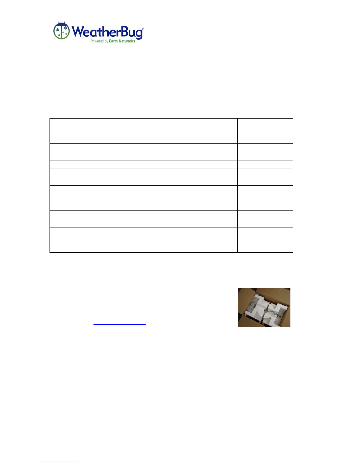
Please carefully unpack, set out, and identify each part and
inspect for damage. If any damage is noticed, please call
WeatherBug Weather Station Technical Support at 800-6244205 or email [email protected]
Release 1, Version 1.0 -7- February 2011
Page 8
HD MotionCam Installation Manual
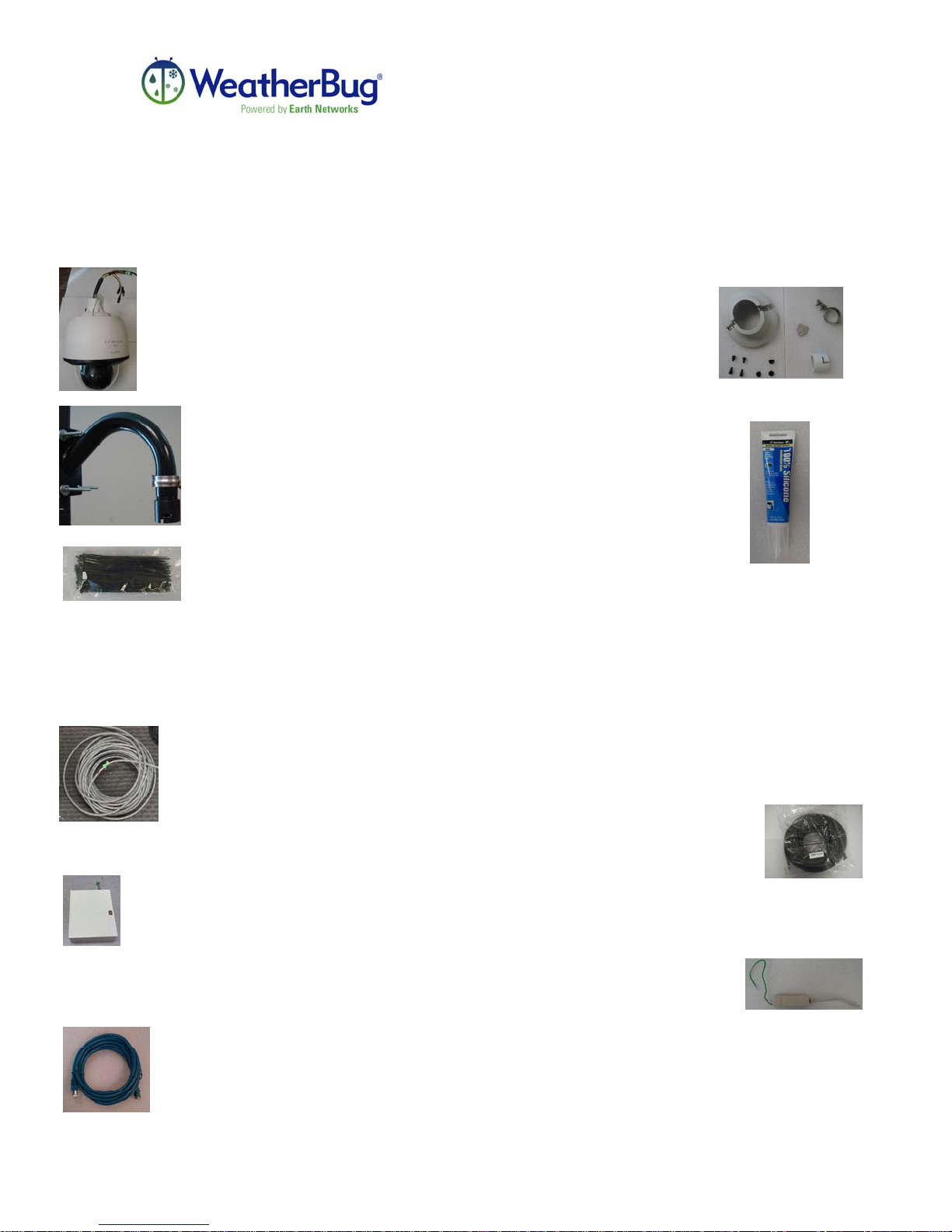
HD MotionCam in Housing
Mounting Arm
Install Sealant
Cable Ties
100 ft Power Cable
Outdoor Components
Camera Support with Clamp, Connector for
Camera and Mounting Arm, 3 Rubber Plugs,
Enclosure for Top of Housing, and Spare
Screws
Indoor Components
200 ft Ethernet Cable
Power Supply
5 ft Ethernet Cable
Release 1, Version 1.0 -8- February 2011
Network Surge Suppressor
Page 9

HD MotionCam Installation Manual
Tools Needed
(Not supplied by WeatherBug)
• Wire cutters and pliers
• #2 Phillips screwdriver
• 10 mm wrench
• Heavy-duty drill with bits sized up to 1-1/4” – bits must be appropriate for
material being drilled into (masonry, wood, metal, etc.) and must be long enough
to penetrate the support walling from exterior to interior (possibly as much as 10”
or more).
• Socket drivers, designed to be used with a drill, of the size(s) needed to fit the
screws intended for use in mounting the HD MotionCam.
• Fish Tape to pull cable through wall
• Electrical Tape to tape the ends of cables for protection and to hold connectors
and cables together.
• Bolts/Screws needed to attach the mounting arm to the wall will vary according to
several factors. Both the composition of the mounting surface and the weight of
the unit (approximately 16 pounds) must be taken into account.
• An adjustable ladder
Release 1, Version 1.0 -9- February 2011
Page 10

HD MotionCam Installation Manual
Site Evaluation
All sites will have certain building restrictions. To get the most out of the camera, a
location needs to be chosen that will present the least restrictions.
The sky, sun, and clouds are important elements in the captured images. A “perfect”
picture includes about 50% sky and about 50% earth.
Remember that the camera will be operating throughout the year. A good view in the late
fall or winter may be obstructed by tree growth in the spring and summer.
Spend time looking at the lighting and shading based on the time of day, types of
weather, and time of year. It is best to center the camera facing toward the prevailing
winds – generally westerly in the United States. If you invest the time now in site
evaluation, your efforts are sure to pay off in the end.
The camera must also be securely mounted to avoid distortion of the camera images. The
mounting arm must be wall mounted for optimal stabilization. The camera should be
mounted high enough so that there is a clear view of the horizon. The unit should be
mounted so that it is easily accessible. This will aid in any maintenance or adjustments
that may have to be made. Once you have chosen the direction you want the camera to
face, it should be mounted on the outermost wall in that direction. This will keep any
roofs and unnecessary structures out of your camera view.
Select and verify a route to run the cables from the camera to the interior of the building.
Note: Keep in mind that the unit comes with 100 feet of power cable that must
reach from the camera to a power outlet. The unit also comes with 200 feet of
Ethernet cable that must reach from the camera to the network connection. Any
cable routed on the building structure exterior must be secured and routed in a
conduit.
THE MAXIMUM LENGTH OF POWER CABLE IS 100 FT.
Release 1, Version 1.0 -10- February 2011
Page 11

HD MotionCam Installation Manual
Installation
Indoor Preliminary Setup
SETTING THE HD MOTIONCAM UP INDOORS ON THE NETWORK IS
ESSENTIAL FOR THE SUCCESSFUL OUTDOOR INSTALLATION OF YOUR
CAMERA.
Network Requirements: Port 21 TCP outbound for FTP images must be open
for the internal IP address of the camera.
Port 80 TCP inbound must be open in order to operate the camera and view
streaming data from any computer.
Internet Explorer must be installed on the computer used for retrieving the IP
address of the camera and it also must be installed on the computer used for
viewing live images from the camera.
By following these preliminary steps you will have the ability to obtain the internal
IP address of the HD MotionCam, which you need in order to view the live video
transmitted from the HD MotionCam. It is imperative that you install the camera
indoors initially in order to guarantee that the camera is working as it should.
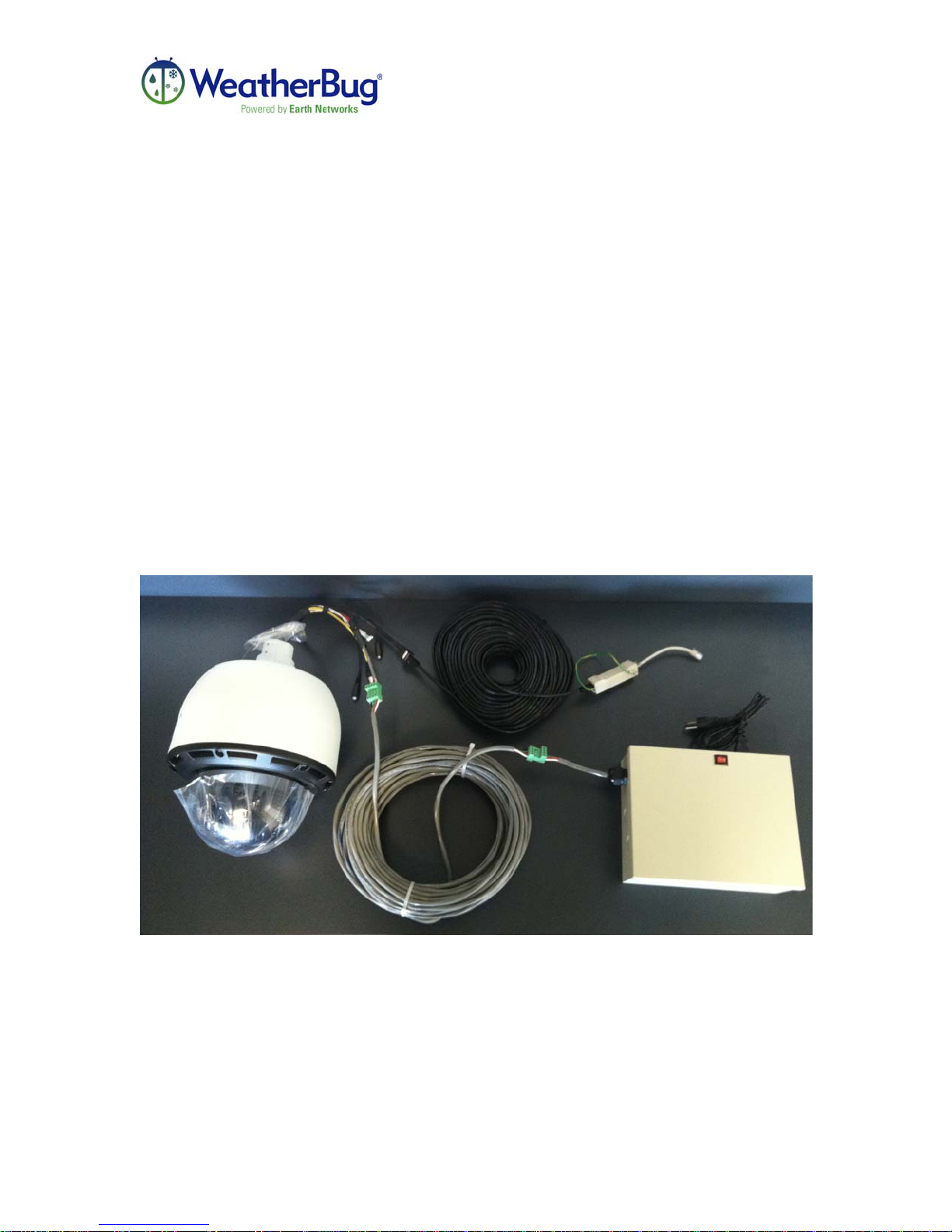
In order to test the camera indoors the following supplied equipment will be needed:
• HD MotionCam
• 200 ft Ethernet Cable
• 100 ft Power Cable
• Power Supply
• Network Surge Suppressor
Access to a computer running on the same subnet as the network connection that will be
used to connect the camera to for this test is needed. An electrical outlet needs to be
nearby as well.
Release 1, Version 1.0 -11- February 2011
Page 12
HD MotionCam Installation Manual
1. Set the dome of the camera on a soft cloth or soft surface while setting up the
camera to avoid scratching the clear dome.
2. Plug one end of the 200 ft Ethernet cable into the camera where the black
connection is labeled “LAN”.
3. Plug the other end of the 200 ft Ethernet cable into the network surge suppressor.
4. Plug the 5 ft Cat 5 Network Ethernet cable into the other end of the network surge
suppressor.
5. For internet transmission, plug the opposite end of the 5 ft Cat 5 Network
Ethernet Cable into the network connection.
6. Plug one end of the 100 ft power cable into the camera using the matching green
connection.
7. Plug the other end of the 100 ft power cable into the matching green connection
on the power supply.
8. For power, plug the power supply into an electrical outlet.
9. Once everything is connected, wait 2 minutes for the camera to power on
completely then skip to the next section titled “Viewing Live Video and Captured
Images” to confirm camera setup.
Release 1, Version 1.0 -12- February 2011
Page 13
HD MotionCam Installation Manual
Viewing Live Video and Captured Images
Live Video
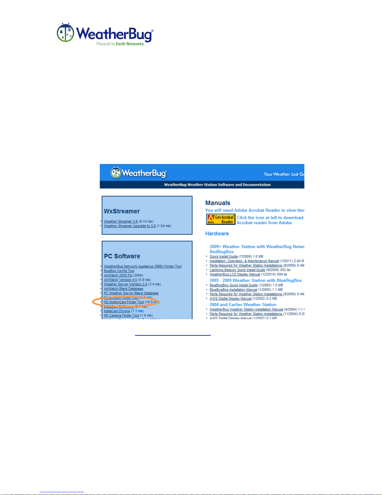
In order to obtain live video from the camera, acquire the internal IP address of
the camera. To do this, download the finder tool from the internet. Open an
Internet Explorer web browser on a computer connected to the same subnet as the
camera. THE HD MOTIONCAM ABSOLUTELY MUST BE CONNECTED
TO THE SAME SUBNET AS THE COMPUTER USED TO AQUIRE THE
INTERNAL IP ADDRESS OF THE CAMERA.
1. To begin, visit http://download.aws.com. Click on the link that says “HD
MotionCam Finder Tool”
Release 1, Version 1.0 -13- February 2011
Page 14
HD MotionCam Installation Manual
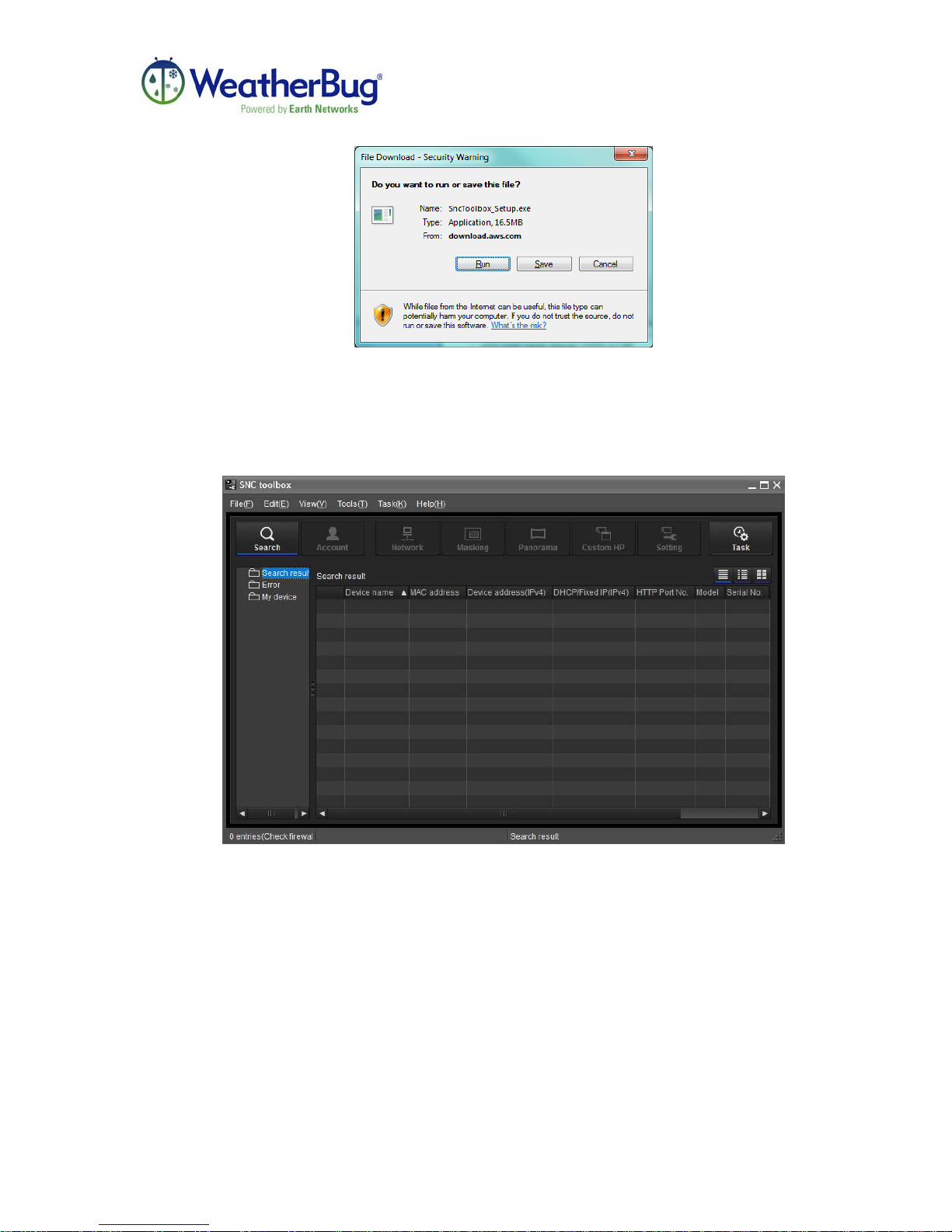
2. Select RUN and follow the steps as prompted to finish installation of the SNC
Toolbox.
3. Once FINISH is clicked in the installation wizard, go to the start menu and
open the SNC Toolbox application.
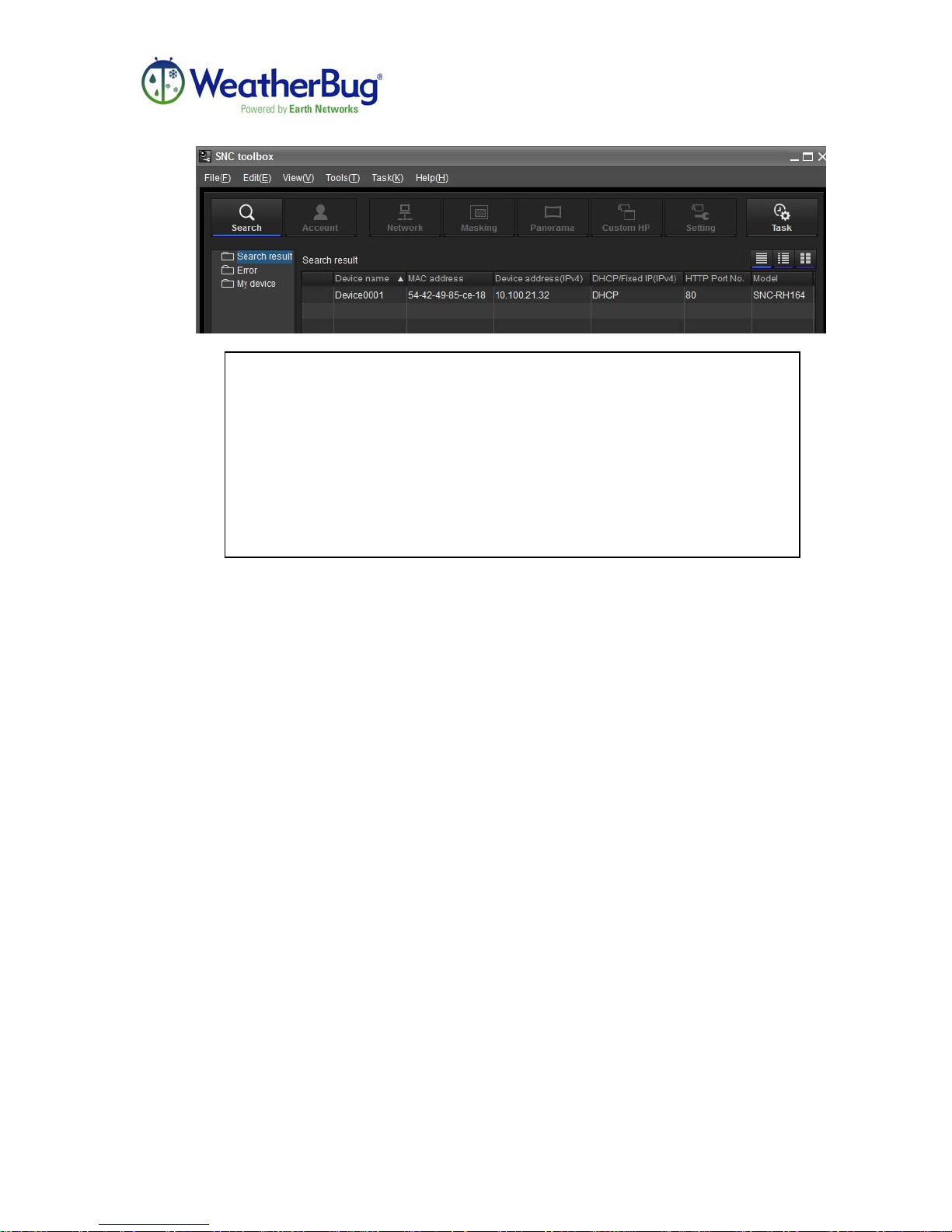
4. If the IP address is not immediately available, click the SEARCH button at the
top left of the window. Make sure the camera has been connected for 2
minutes before attempting to find the IP address.
Release 1, Version 1.0 -14- February 2011
Page 15
HD MotionCam Installation Manual
Note: If the IP address is not listed, the computer used for access is most
likely not connected to the same subnet as the camera and the testing will
need to be finished in another location where the computer and camera
are on the same subnet. If the camera is connected to the same subnet as
the computer and the camera is installed properly, the local network may
not assign DHCP IP addresses. The camera will need to be connected to
a switch that is also connected to the computer in order to set a Static IP
address. Please refer to the section titled, “Setting a Static IP Address for
your HD MotionCam” on page 22.
5. Double click the address to pull up the configuration and operation controls
for the camera. The Device address may also be directly typed into an address
bar of an Internet Explorer browser.
IMPORTANT: Internet Explorer must be installed on the computer used for
attempting to view the live video.
Release 1, Version 1.0 -15- February 2011
Page 16
HD MotionCam Installation Manual
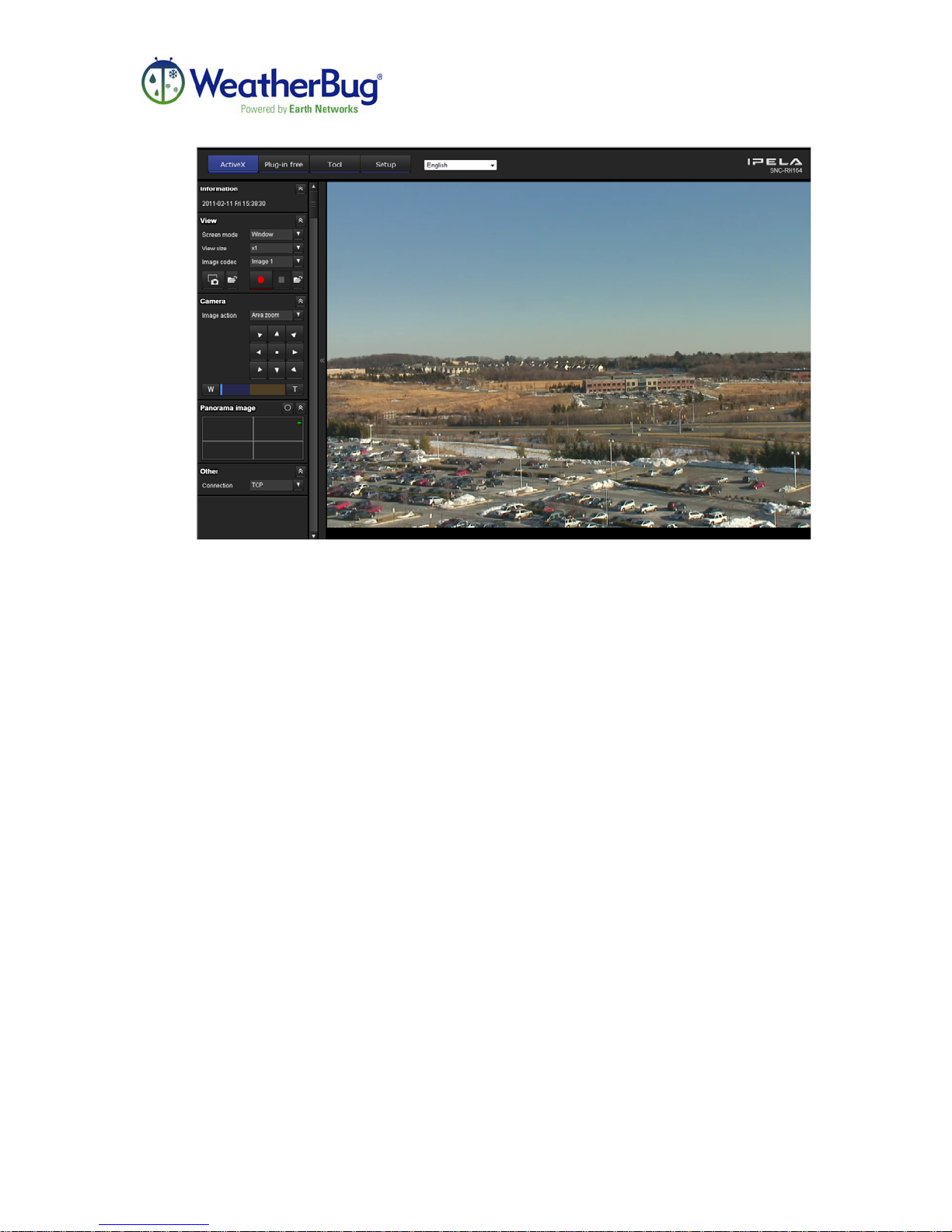
Utilization of the pan/tilt/zoom functionalities of the HD MotionCam is possible
through the page pictured above.
Captured Images
In order to obtain captured images Port 21 TCP outbound must be open for FTP o
and WeatherBug Weather Station Technical Support must be contacted at 800624-4205 or email [email protected]. The camera must be enabled through
headquarters in order for captured images to be available through the WeatherBug
website. Once the camera is enabled, using a web browser on a computer
connected to a Local Area Network (LAN), images can be viewed from the
camera by visiting http://weather.weatherbug.com and searching for the location
name.
Now that captured images and live video are visible from the HD MotionCam and
available on the network, the rest of the installation may be completed.
Release 1, Version 1.0 -16- February 2011
Page 17

HD MotionCam Installation Manual
Routing the Cables
It is best to work with a team of at least two people, as cable will have to be handled from
both the inside and the outside of the building.
Keep in mind the standard HD MotionCam package contains 100 feet of power cable and
200 feet of Ethernet cable. These cables must reach from the camera to the
corresponding network and power connections.
Note: The HD MotionCam Ethernet Cable is not UV rated. Cable must
be routed in conduit when running outdoors to protect it. The cable
should be run inside as much as possible. Cable can be run in ceiling
spaces. Both cables can be routed together if the internet and power
connections are within 100 ft. If the internet and power connections
are separate, than it is recommended each cable be run separately to
their corresponding connection points indoors.
1. With the end of the cables as close as possible to the network and power
connections that will be used, and allowing about eight extra feet, tape the end of
the cables to something sturdy in the area to hold it in place, keeping in mind that
the cables cannot run directly across the floor and will have to be attached to areas
such as the base of walls when the job is complete.
2. Run the cables to the general area that the camera will be mounted outside; fish
tape may be used here to make this step easier.
3. Tape the cables down as close to where the camera will be mounted as possible,
keeping in mind the cables will need to be run through the mounting arm for the
camera.
4. At the outside location where the camera is to be mounted, as close to the camera
as possible, install conduit to cover any outside portion of the cables. Make sure
the cables will reach through the mounting arm to where the camera will be
mounted.
Release 1, Version 1.0 -17- February 2011
Page 18
HD MotionCam Installation Manual
Outdoor Installation
For the following steps, the items listed below will be needed:
• Mounting Arm
• Install Sealant
• HD MotionCam in Housing
• Camera Support and Clamp
• Connector for Camera to Mounting Arm
• 3 Rubber Plugs
• Enclosure for Top of Camera Housing
• Cable Ties
• 5 mm Allen Wrench
1. Make sure the mounting arm will be mounted high enough so that the camera
pan/tilt/zoom features can be utilized. On the outside wall where the cables have
been pulled through and the camera is to be mounted, attach the mounting arm to
the wall and secure tightly (hardware not included). The mounting arm should go
over the hole created for the cables. The Power and Ethernet Cables should be fed
through the Mounting Arm for the camera connection to be
made. Once the Mounting Arm is secured to the wall, use the
Install Sealant around the outside of where the mounting arm
meets the wall to keep moisture from leaking behind the
mounting arm and down the cables.
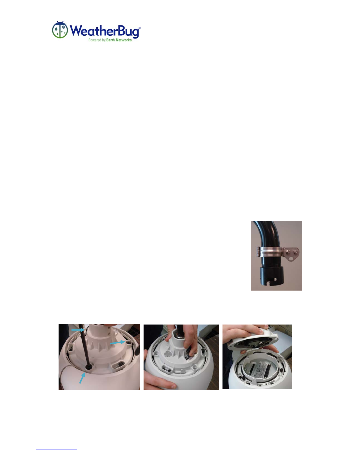
2. Screw the threaded connector onto the mounting arm that will
also connect to the camera. Place the clamp with the
triangular attachment above the connector. Pictured to the
right.
3. Using the provided Allen Wrench, loosen the three screws
connecting the top of the camera housing to the camera itself. Once the screws
are loose, rotate the top of the housing CCW to separate the top from the bottom.
Release 1, Version 1.0 -18- February 2011
Page 19
HD MotionCam Installation Manual
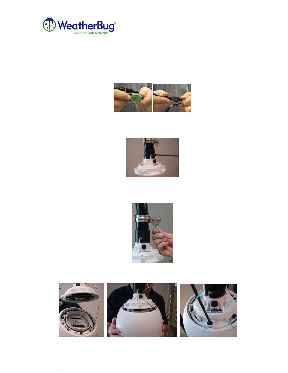
4. With the top of the camera housing in hand, connect the Power and Ethernet
Cables from the Mounting Arm opening to the top of the camera.
5. Feed the attached cables into the mounting arm and line up the two screws with
the two openings on the connector. Push the top of the housing into the openings
and rotate the housing to the right to secure into place. Tighten the screws into the
threaded collar with a screwdriver for further security.
6. On the bottom portion of the housing, including the camera, take the wire
connected to the carabineer and attached the carabineer to the triangular piece on
the clamp attached to the mounting arm. This will support the weight of the
camera on the mounting arm while installation is finished and/or repairs are made.
7. Line up the connection points between the camera in the housing and the top of
the housing. Once the connection is made, rotate the bottom to the right to hold
the camera in place. Tighten the three screws with the provided Allen Wrench.
Release 1, Version 1.0 -19- February 2011
Page 20
HD MotionCam Installation Manual
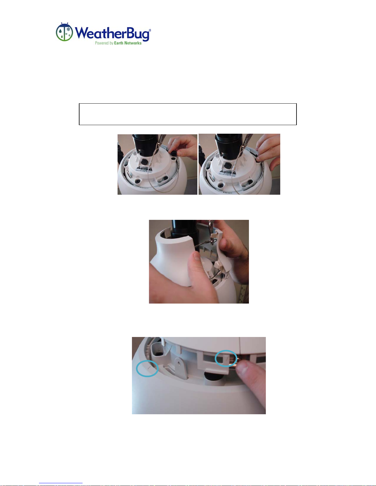
8. Using the 3 rubber plugs, insert one over each of the screws. This step is very
important.
THE RUBBER PLUGS ARE THE ONLY PROTECTION AGAINST
MOISTURE GETTING INTO THE CAMERA BASE.
9. To complete installation, the enclosure for the top of the housing needs to be
attached to the camera base. Open the enclosure and place around the top of the
housing and bottom of the Mounting Arm.
10. Snap the enclosure shut. Line up the arrow on the top of the enclosure with the
arrow on the camera housing bottom. Rotate the enclosure to the right to lock
into place. The arrows are pictured below.
11. Use the supplied cable ties to clean up any loose cables (if applicable). Cut off the
remaining ends of the cable ties.
12. The HD MotionCam needs to be grounded according to local electrical code.
Release 1, Version 1.0 -20- February 2011
Page 21

HD MotionCam Installation Manual
Indoor connections
For the following steps, the items listed below will be needed:
• Network Surge Suppressor
• Power Supply
• 5 ft Ethernet Cable
1. Plug the indoor end of the 200 ft Ethernet Cable into one end of the Network
Surge Suppressor.
2. Plug one end of the 5 ft Ethernet Cable into the other end of the network surge
suppressor.
3. For internet transmission, plug the remaining end of the 5ft Ethernet Cable into
the network connection at the location desired inside of the building.
4. Plug the indoor end of the 100 ft Power Cable into the power supply.
5. For power, plug the power supply into an electrical outlet.
Note: The Power Supply MUST be installed indoors. The power supply
is not weatherproof.
6. As long as network settings were confirmed during the preliminary setup and after
giving the camera enough time to boot up, approximately 2 minutes, installation is
complete!
Camera setup is now complete. As long as the camera is installed using DHCP and
confirmation of image transmission has been completed by calling WeatherBug Weather
Station Technical Support at 800-624-4205, the camera is fully operational. If the
camera requires a static IP address, adjust the camera settings by following the steps in
the following section entitled, “Setting a Static IP Address for the HD MotionCam.”
Release 1, Version 1.0 -21- February 2011
Page 22
HD MotionCam Installation Manual
Setting a Static IP Address for the HD MotionCam (Optional)
If the internal IP address of the HD MotionCam is not known, please refer to the Live
Video section of Viewing Live Video and Captured Images. Once the SNC Toolbox is
downloaded, configure the IP address as shown below as long as the camera is directly
connected to the computer through a switch.
If the IP address is known, open an Internet Explorer window and enter the IP address in
the address bar of the window and hit enter.
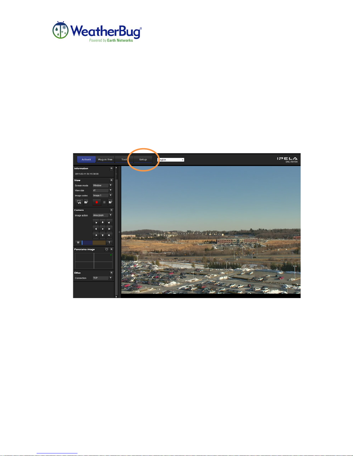
1. Once the window is open click on the SETUP button on the top bar of the
webpage, circled here.
Release 1, Version 1.0 -22- February 2011
Page 23
HD MotionCam Installation Manual
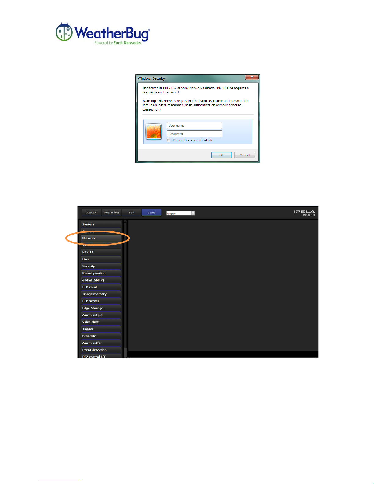
2. A window will pop-up prompting the entry of a User Name and Password. The
camera has been programmed with a generic user name and password. The user
name is admin and the password is WxBugHD. The password is case sensitive.
3. Once logged in, click on the NETWORK button on the left side of the page,
circled here.
Release 1, Version 1.0 -23- February 2011
Page 24
HD MotionCam Installation Manual
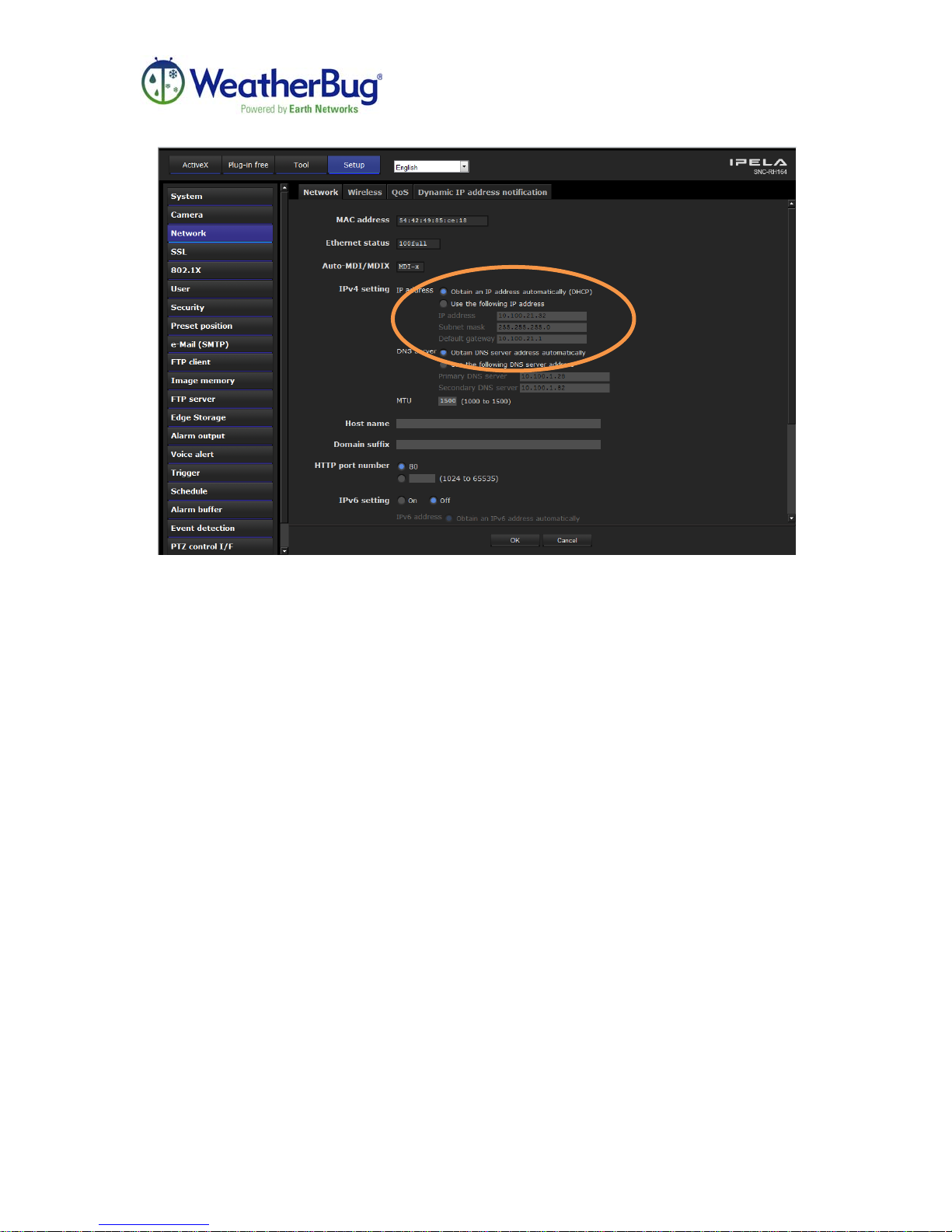
4. Near the middle of the window, click the radio button labeled “Use the following
IP address.” Enter the static IP information in the three boxes below, circled here,
and then click OK on the bottom of the page to save.
Release 1, Version 1.0 -24- February 2011
Page 25

HD MotionCam Installation Manual
Troubleshooting
Difficulties Acquiring an IP Address
First, make sure the camera is connected to the same subnet as the computer that is being
used to acquire the address. If this is confirmed, but the camera is still not acquiring an
address, the network may not automatically assign DHCP IP Addresses. It may be useful
to connect a network cable directly to the computer being used through a switch to
guarantee the computer can talk to the camera. A Static IP address can be assigned by
going to download.aws.com and downloading the HD MotionCam finder tool and
following the steps in this manual outlined in the section titled, “Setting a Static IP
Address for Your HD MotionCam.”
Power Issues
In cases of malfunction, the most common cause is lack of power to the HD MotionCam.
Be sure to check power supplies and connections to ensure that the HD MotionCam has
the proper power supply and that the components are turned on. When the camera is
powered on, the booting process and movement of camera is audible when standing
directly next to the unit.
Captured Images Not Visible
If the station power has been verified and images are available locally but captured
images are not retrievable through http://weather.weatherbug.com, verify Port 21 TCP for
outbound traffic is open for FTP.
Live Video Not Available
IMPORTANT: Once power is connected to the camera, make sure 2 full minutes have
passed before attempting to access live video from the camera.
If trying to view live video on a computer on the same subnet as the camera, verify the IP
address is correct. The finder tool may need to be reopened to do this if DHCP was used.
If the camera was installed using a static IP address, please verify the correct IP address
is being used by contacting the local network administrator.
If viewing live video from a computer that is not on the same subnet that the camera is
installed upon is desired, verify that Port 80 TCP is open for inbound traffic to the
camera.
Release 1, Version 1.0 -25- February 2011
Page 26

HD MotionCam Installation Manual
In the event that the provided troubleshooting steps have been attempted and the camera
is still inoperable, contact WeatherBug Weather Station Technical Support at 800-6244205 or email [email protected].
Maintenance
There is little maintenance needed for the HD MotionCam. As long as the camera
housing remains tightly closed and the three rubber plugs are in place, there should rarely
be a need to clean anything inside the camera top enclosure.
The clear dome surrounding the camera may be very loosely wiped with a dry, soft cloth
to remove dust and debris. The dome can then be wiped with the cloth using a very small
amount of water.
DO NOT use volatile solvents such as alcohol, benzene, thinners, or ammonia as they
may damage the surface finishes. DO NOT use abrasive cleaners, cloths, or sponges.
Please keep in mind that most household cleaners (such as Windex, etc.) contain
ammonia.
Release 1, Version 1.0 -26- February 2011
Page 27

HD MotionCam Installation Manual
Additional Information
This product has been designed with safety in mind. However, if not properly installed
and used, any electrical product can cause fires. To avoid such incidents, please be sure
to follow these guidelines.
• Be sure to follow all general safety precautions.
• In case of a system breakdown, discontinue use, unplug the unit and all other
cables, and contact WeatherBug Weather Station Technical Support at 800-6244205 or email [email protected].
• In case of abnormal operation:
Unit is emitting smoke or an unusual smell
Water or other foreign objects enter the housing
The unit is dropped or damaged
• Disconnect the camera power cable and other connecting
cables
• Contact WeatherBug Weather Station Technical Support at
800-624-4205 or email [email protected].
Release 1, Version 1.0 -27- February 2011
Page 28
HD MotionCam Installation Manual
Specifications
Item Specification
Frame Transfer Up to 30 frames per second (FPS)
Electronic Shutter Speed ½ to 1/10,000 s
Lens Type Auto-focus zoom lens
Zoom Ratio 10x
Horizontal Viewing Angle 5.4 to 50 degrees
Focal Length F=5.1 to 51mm
Pan Angle 360 degrees endless rotation
Pan Speed 400 degrees/s (max.)
Tilt Angle 210 degrees
Tilt Speed 400 degrees/s (max.)
Power Requirements AC24V
Power Consumption 80 W max.
Dimensions 9 3/8 x 13 5/8 inches (238 x 346 mm)
Weight of Camera and Housing Approximately 16 pounds / 7.26 kg
Operating Temperature Range -40° to +122° F / -40° to +50° C
Release 1, Version 1.0 -28- February 2011
 Loading...