

Page 1

IP-M945A
Series
(Motherboard)
INSTALLATION GUIDE
Installation Guide Revision A0
600C002945AA0
Page 2

Page 3

i
COPYRIGHT©
All rights reserved. The information contained in this guide has been
validated and reviewed for accuracy. No patent liability is assumed with
respect to the use of the information contained herein. While every
precaution has been taken in the preparation of this guide, the Manufacturer
assumes no responsibility for errors or omissions.
No part of this publication may be reproduced, stored in a retrieval
system, or transmitted in any form or by any means, electronic, mechanical,
photocopying, recording, or otherwise, without the prior written permission of
Manufacturer.
TRADEMARK™
Intel®, Pentium® and Celeron® are registered trademarks of Intel®
Corporation.
Microsoft® and Windows® are registered trademarks of Microsoft
Corporation.
All products and company names are trademarks or registered
trademarks of their respective holders.
These specifications are subject to change without notice.
Installation Guide Revision A0
June 2006
Page 4

ii
CONTENTS
SECTION 1 INTRODUCTION 1
1.1 Unpacking IP-M945A Series 1
1.2 Description 3
1.3 Features 3
1.3.1 Chipsets Features 3
1.3.2 Ultra ATA/66/100 4
1.3.3 Hardware Monitoring 4
1.3.4 I/O Shield Connector 4
1.3.5 Power-On/Off 5
1.3.6 IP-M945A Series Overview 5
1.3.7 System Block Diagram 6
1.4 Specifications 7
SECTION 2 INSTALLATIONS 9
2.1 System Installation 9
2.1.1 CPU Installation 9
2.1.2 Heat Sink Installation 10
2.1.3 DDR2 Memory Module Installation 11
2.1.4 Setting Jumpers 13
2.2 Board Layout 14
2.3 Jumper Setting 15
2.4 Connector’s Description 18
Page 5

iii
CONTENTS
SECTION 3 AWARD BIOS SETUP 35
3.1 BIOS Instructions 35
3.2 Main Menu 36
3.3 Standard CMOS Features 38
3.4 IDE Adapters 40
3.5 Advanced BIOS Features 42
3.6 Advanced Chipset Features 47
3.7 Integrated Peripherals 50
3.8 Power Management Setup 56
3.9 PnP/PCI/PCI-E Configurations 60
3.10 PC Health Status 62
3.11 Frequency/Voltage Control 63
3.12 Load Fail-Safe Default 64
3.13 Load Optimized Defaults 64
3.14 Supervisor/User Password Setting 65
3.15 Exit Selecting 66
Page 6

iv
Page 7
1
INTRODUCTION
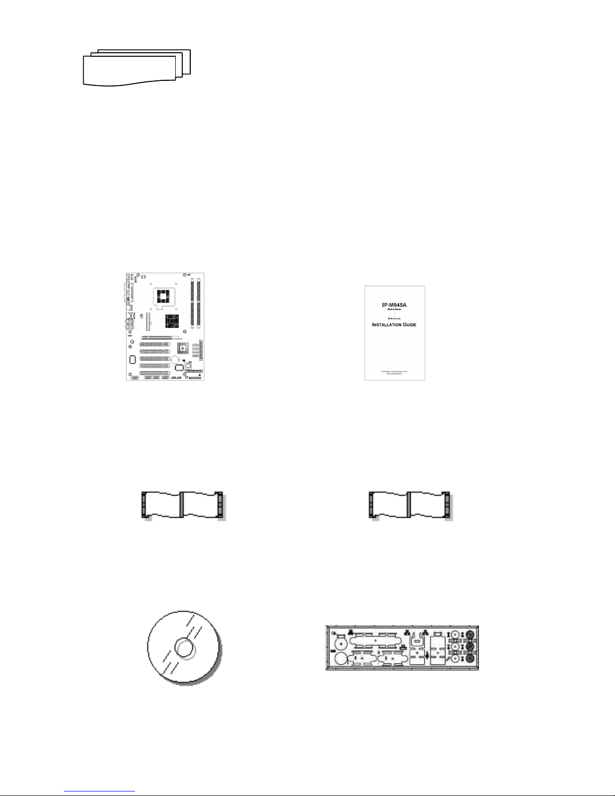
1.1 Unpacking IP-M945A Series
1. Take out the IP-M945A series unit from the carton box, check if the unit is
properly secure in the plastic bag.
2. Check the contents of the carton box: (Sketch map)
Motherboard Installation Guide
ATA-66/100 HDD ribbon cable Floppy ribbon cable
Driver CD I/O Shield
S
ECTION
1
Page 8

Introduction
2
S-ATA cable (2 Sets) Extend to front panel cable
(for K/B & M/S)
COM2 ribbon cable (1 Set)
(for RS-232)
3. Optional Kits
USB cable COM3/COM4 ribbon cable
(for USB2.0) (for RS-232)
S-ATA cable
Page 9

Introduction
3
1.2 Description
The IP-M945A Series combines the high performance and exceptional
value of Intel® 945G chipset with a full-featured board. The Intel® advanced
945G chipset support regular socket LGA775-pins Intel® Pentium® 4 /
Celeron® D processors of 3.8GHz and support Intel® Pentium D® to 3.4GHz,
that memory base on the FSB 533/800/1066MHz operation supports dual
channel DDR2 400/533/667 SDRAM interface. In the meantime, the 945G
chipset integrated the graphic function. The IP-M945A system memory size
can be up to 2GB DDR2 memory, onboard Intel® 82573 PCI-E Ethernet
controller (support 10/100/1000 Base-TX Ethernet), Audio and with 4 COM
ports, besides the IP-M945A add one 6-pins connector that can extend to
front of chassis for KB & MS.
The 82801GB I/O Controller Hub (ICH7) employs the Intel® Accelerated
Hub Architecture to make a direct connection from the graphics and memory
to the integrated Ethernet controller, such as the IDE & S-ATA controllers
(ATA/33 or ATA/66 or ATA/100), eight USB ports that are supported USB
1.1/2.0 standard meets the performance, stability and reliability
requirements.
1.3 Features
1.3.1 Chipsets Features
The IP-M945A is base on the Intel® 945G chipset, offers users the
integration graphic, Ethernet, Audio function. The features of chipset are as
below:
Enhanced integrated graphics & system performance:
- Support 533/800/1066 MHz FSB
Memory:
- DDR2 533/667 SDRAM
- Dual channel up to 2.0GB Max. Memory
- 2 x DDR2 DIMM sockets
Page 10
Introduction
4
O Connectivity – ICH7:
- 8 Hi-Speed USB2.0 ports
- AC’97 Codec
- 4 Serial ATA II ports
- 1 x PCI-Express by 16 & 5 x PCI slots
1.3.2 Ultra ATA/66/100
The ICH7 provides one channel Ultra ATA/66/100 Bus Master IDE
controller, that support Ultra ATA/66/100 protocols, perfect for such
demanding applications as real-time video, multimedia, and high
performance operating system. A new IDE cable is required for Ultra
ATA/66/100. This cable is an 80-conductor cable; however the connectors
are, of course, backwards compatible with ATA/33.
1.3.3 Hardware Monitoring
Hardware monitoring allows you to monitor various aspects of your
systems operations and status. The features include CPU temperature,
voltage and RPM of fan.
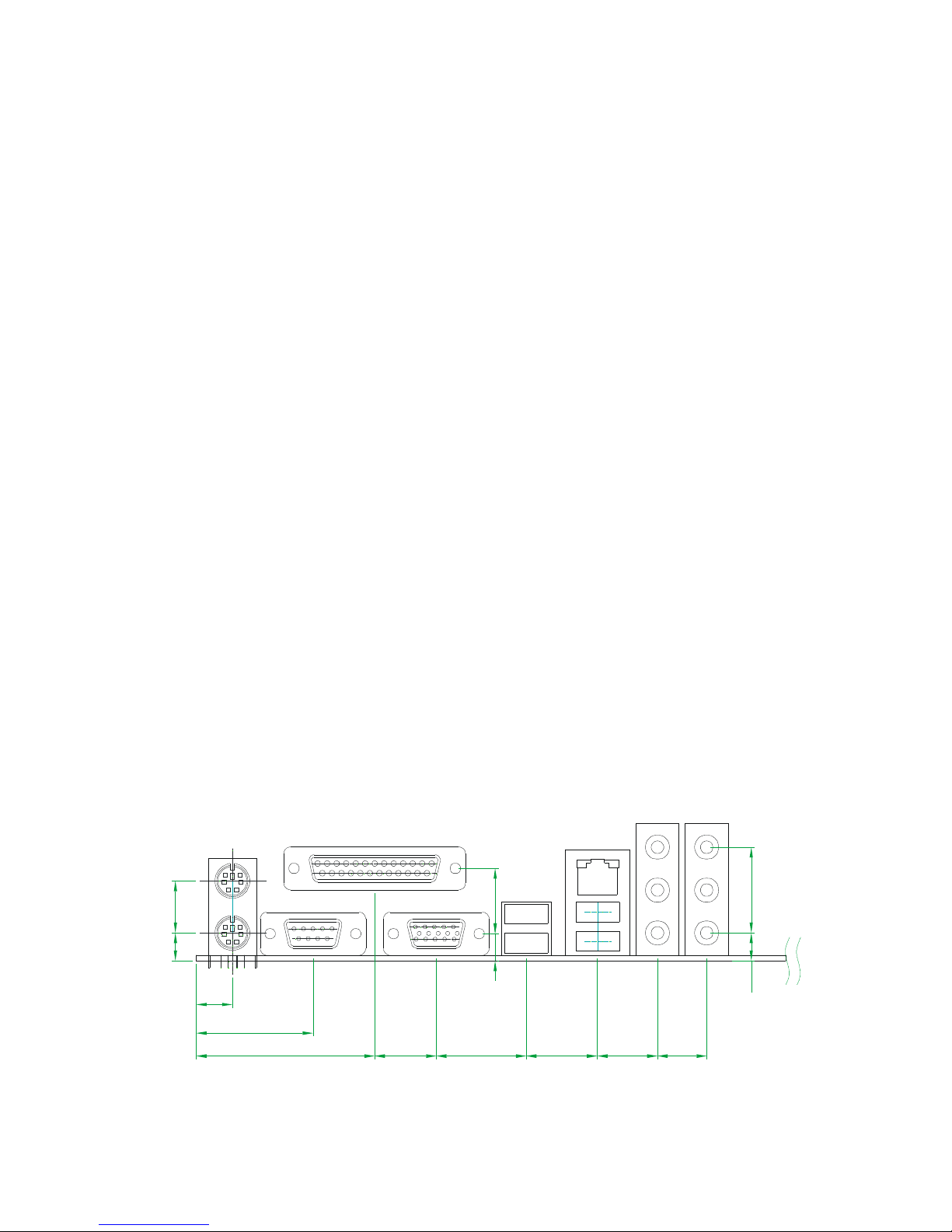
1.3.4 I/O Shield Connector
The board is equipped with an I/O back panel. Please use the appropriate
I/O shield (figure 1).
10.5
34.0
52.0
18.0
26.2
20.8
17.5
14.4
8.1
25.0
8.1
15.2
7.9
19.0
Figure 1: I/O back panel layout
Page 11

Introduction
5
1.3.5 Power-On/Off (Remote)
The board has a single 24-pins connector for ATX power supplies. For
ATX power supplies that support the Remote On/Off feature, this should be
connected to the systems front panel for system Power On/Off button. The
systems power On/Off button should be a momentary button that is normally
open.
1.3.6 IP-M945A Series Overview
Function / Model IP-M945A
Chipset Intel® 945G
Graphic function Yes
Ethernet function Yes
Audio function Yes
EIDE interface 1
Floppy interface 1
Parallel port 1
PCI-E by 16 slots 1
PCI slots 5
Serial ports 4
USB 2.0 ports 8
Fan connectors 3
External KB/MS connector 1
Page 12
Introduction
6
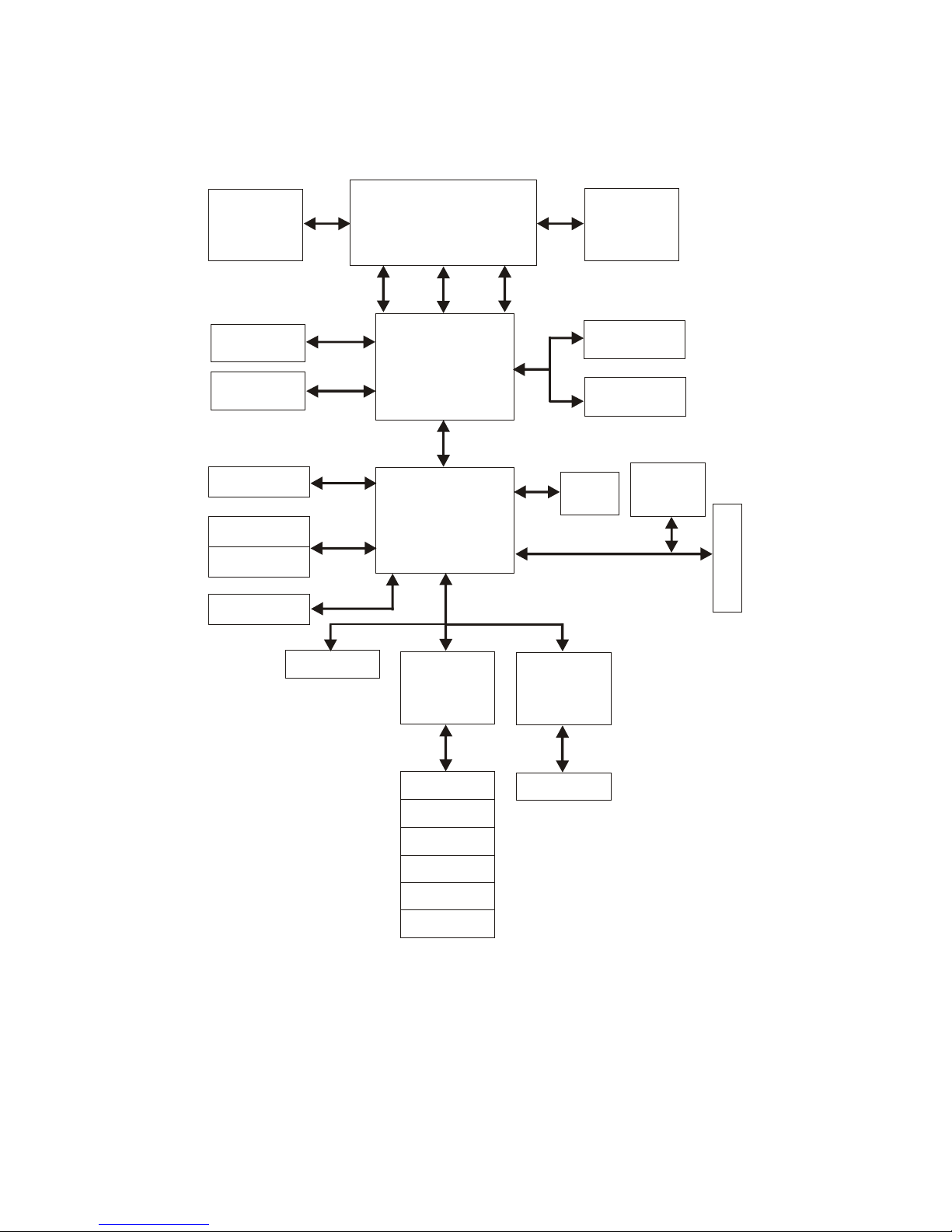
1.3.7 System Block Diagram
PCI / PCI-E BUS
P
C
I
/
P
C
I
-
E
S
L
O
T
S
Intel 82 573
10/ 10 0/100 0
Base-T X
AC97
Audio
Cod ec
P4 LGA 77 5 socke t
Clo ck
VRM
DATACTR LADD R
GMCH (945G )
120 2 FCBGA
ICH 7
652 B GA
Intel G MA
950 Graphi cs
ATA100
USB 2.0
IDE P rim ar y
USB Po rt 1 /2/ 3/ 4
USB Po rt 5 /6/ 7/ 8
SATA P or t1/ 2/3/4
II
SATA
DDR 2 533 /66 7 X1
PCI -E x 16
SLOT
Sup er I/O
IT8 71 2
FWH
Key board
Mouse
COM 1/2 Po rt
LPT Po rt
Flo pp y
DDR 2 533 /66 7 X1
Sup er I/O
IT8 71 2
COM 3/4 Po rt
PCI -E x1 6
Dig it al I/O Port
Figure 2: System Block Diagram
Page 13

Introduction
7
1.4 Specifications
Processor:
- Support Intel® Pentium® 4/Celeron® D processor with LGA775-pins
package, processor operating at 2.4GHz and up to 3.8GHz
- Intel® Pentium® D processor with LGA775-pins package, processor
operating up to 3.4GHz
- System bus frequency at 533/800/1066 MHz FSB
Chipset:
- Intel® 82945G + ICH7 AGPset
DRAM Module:
- Dual channel two 240-pins socket
- For DDR2 533/667 unbuffer non-ECC SDRAM memory
- Support DDR2 SDRAM up to 2GB (Max.)
PCI-E Gigabit Ethernet Function:
- Intel® 82573 Gigabit LAN, for 10/100/1000 Base-TX Ethernet
- Onboard one RJ-45 Ethernet connector
- Add one set LAN Active, Link LED pin-header for extend to front panel
Audio Function:
- AC’97 audio codec
- Onboard Audio Line_in, Line_out, MIC phone jack
SATA Function:
- Four S-ATA II channel (300MB/s), support up to 4 S-ATA devices
External Connector:
- 1 x 6-pins extend to front of chassis for external KB / MS connector
- 3 x 10-pins serial ports by pin-header, COM2/3/4 for RS-232
(Serial cable with bracket)
- 2 x 10-pins USB connectors (USB cable with bracket)
Expansion Slot:
- 1 x PCI-E by 16 slot
- 5 x PCI slots
Onboard I/O:
- On-Chip I/O integrated with K/B, M/S, FDD, Parallel and Serial,
Fast IR and Power-On controllers
Page 14

Introduction
8
Onboard PCI / IDE:
- Intel® ICH7 south bridge controller
- PCI Rev2.3 Compliant
- ACPI Compliant Power Management
- PCI Bus IDE Port x 1
Rear I/O Connectors:
- PS/2 mouse and PS/2 style keyboard
- D-Sub 25-pins printer port connector
D-Sub 9-pins COM1 serial port connector for RS-232
D-Sub 15-pins VGA connector
- 2 x USB2.0 connectors
- RJ-45 Ethernet and 2 x USB2.0 connectors
- Audio phone jacks for Cen/Lfe-Out, Surr-Out, Side-Out &
Line-In, Line-Out, MIC
BIOS:
- Award Plug & Play BIOS
Form Factor:
- 12” x 8.7” (305 x 220mm) ATX Size
Weight:
- 1.44lb (650g) --- IP-M945A series
Page 15
9
INSTALLATIONS
2.1 System Installation
2.1.1 CPU Installation
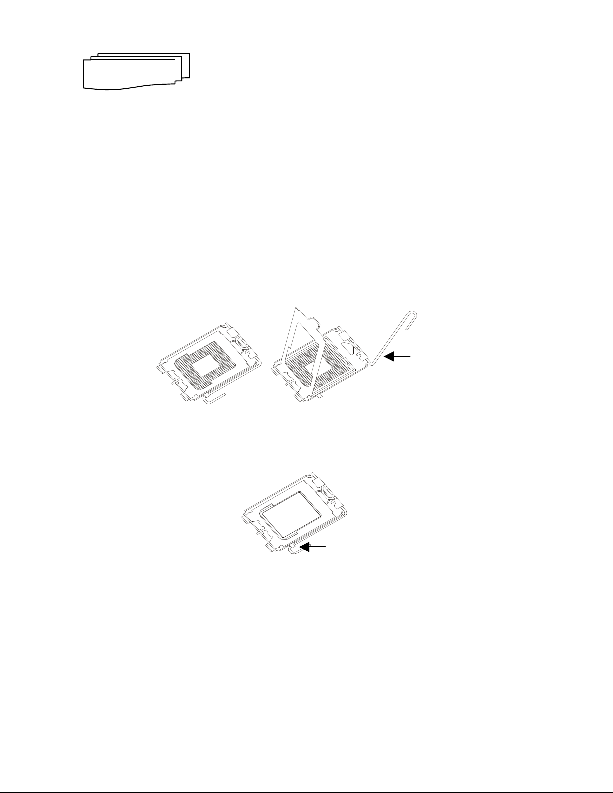
Carefully follow the steps below in order to install the CPU:
1. Check and confirm that you are going to install correctly CPU type and
pin numbers (Figure 3).
2. Lift the releasing lever and cover of the socket LGA775.
3. Align the pin of the CPU against the pinholes of the socket LGA775. Be
sure to pay attention to the orientation of the CPU.
Figure 3: LGA775 CPU Socket
4. Push down the CPU into the LGA775 socket.
Figure 4: Push Down CPU
5. Push down the release lever and lock it against the key hook.
6. Hook the hole in ZIF clip for the CPU cooling fan onto the notch on the
socket LGA775.
7. Place the CPU cooling fan atop the CPU surface.
S
ECTION
2
Hook
Lever
Page 16

Installations
10
8. Push down the opposite side of the ZIF clip and hook it.
9. Slide the head of the clip to left and lock it.
10. Connect the cooling fan cable to the socket. Be careful not to place the
cable on the CPU cooling fan.
Removing a CPU:
1. Before removing the CPU, turn off the IP-M945A series power; then wait
for about 20 minutes until the heat radiation plate of the cooling fan and
the CPU cools down.
2. To remove the CPU, lift the releasing lever of the socket LGA775.
Note: The CPU and the heat radiation plate are hot. They may cause
burns.
To remove the CPU, reverse the installation steps.
2.1.2 Heat Sink & Retention Module Installation
Make sure that good contact is made between the processors and the
heat sinks & fan. Insufficient contact, incorrect types of heat sinks, fans, or
thermal compound used or improper amount of thermal compound applied
on the CPU die can cause the processors to overheat, which may crash the
system.
Page 17
Installations
11
2.1.3 DDR2 Memory Module Installation
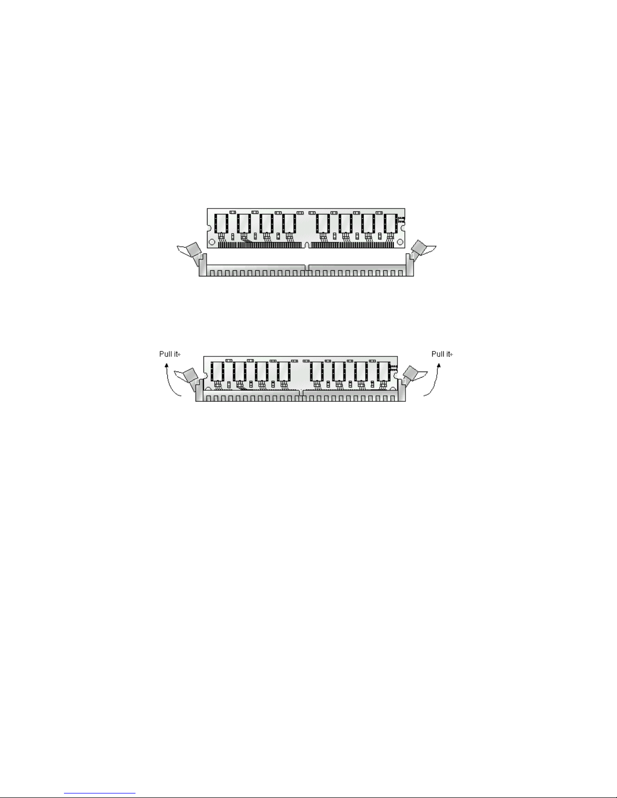
Figure 5 display the notch marks and what they should look like on your
DDR2 DIMM memory module.
DDR2 DIMMs have 240-pins and two notches, that will match with the
onboard DIMM socket. DDR2 DIMM modules are installed by placing the
chip firmly into the socket at a 90-degree angle and pressing straight down
(figure 6) until it fits tightly into the DDR2 DIMM socket.
Figure 5: DDR2 DIMM Memory and 240-pins Socket
Figure 6: Memory Installation
Page 18

Installations
12
Carefully follow the steps below in order to install the DDR2 DIMMs:
1. To avoid generating static electricity and damaging the DDR2 DIMM,
ground yourself by touching a grounded metal surface or using a ground
scrap before you touch the DDR2 DIMM.
2. Do not touch the connector of the DDR2 DIMM. Dirt residue may cause
a malfunction.
3. Hold the DDR2 DIMM with its notch to the front side of the IP-M945A
Series and insert it completely into the socket. A DDR2 DIMM should be
inserted into the inner socket first. Guiding the hole at each end of the
DDR2 DIMM over the retaining post at each end of the DDR2 DIMM
socket.
4. If you install two DDR2 DIMMs, install the second DDR2 DIMM using the
same procedure as above.
5. If DIMM does not go in smoothly, do not force it. Pull it all the way out
and try again.
6. Make sure the DDR2 DIMM is properly installed and locked by the tabs
on both sides of the socket.
Removing a DDR2 DIMM:
To remove the DDR2 DIMM, use your fingers or a small screwdriver to
carefully push away the plastic tabs that secure the DDR2 DIMM at each
end. Lift it out of the socket.
Make sure you store the DDR2 DIMM in an anti-static bag and must be
populated the same size and manufactory of memory modules.
Page 19

Installations
13
2.1.4 Setting Jumpers
There are jumpers on the system board of the IP-M945A Series. You
can set the jumpers to make the necessary operations.
Figure 7: Jumper Connector
For any three-pins jumpers (Figure 7), the jumper setting is 1-2 when
the jumper connects pin 1 and 2. The setting is 2-3 when pin 2 and 3 are
connected and so on. You see one of the lines surrounding jumpers is thick,
which indicates pin NO.1.
To move a jumper from one position to another, use needle-nose pliers
or tweezers to pull the pin cap off the pins and move it to the desired
position.
Page 20
Installations
14
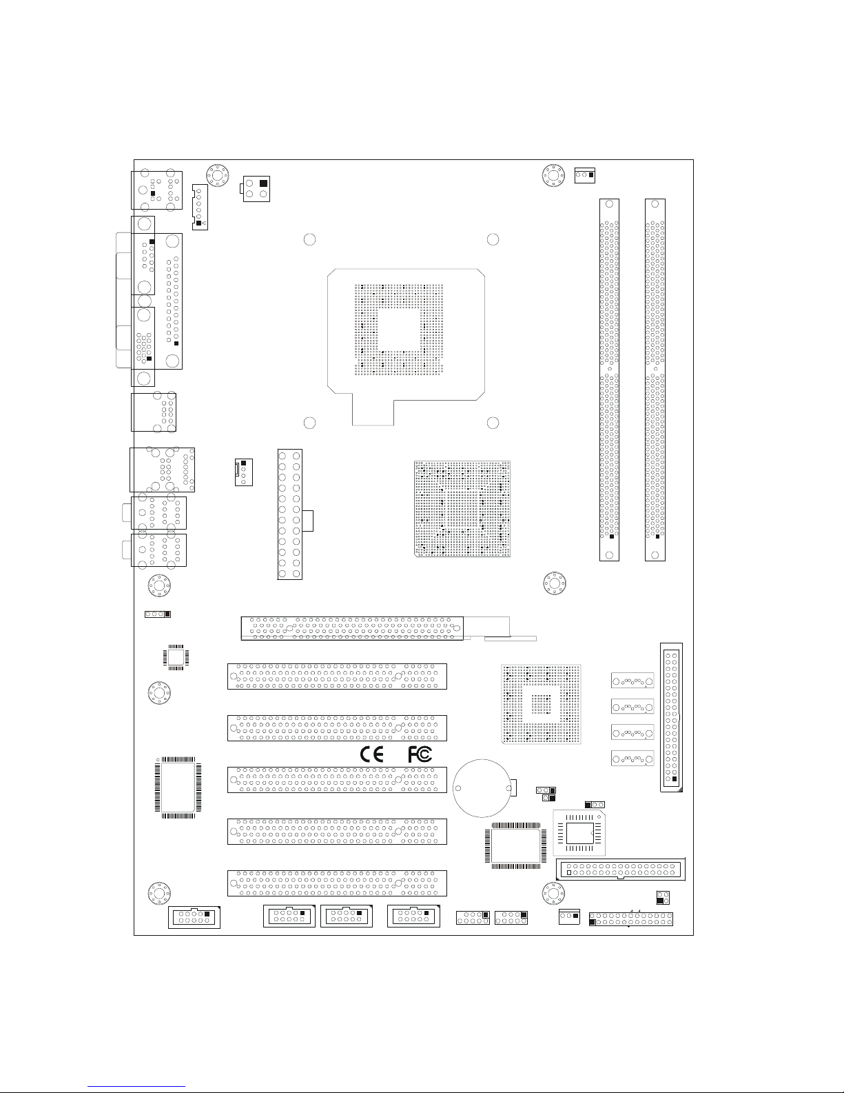
2.2 Board Layout
Jumper & Connector Location
CN6
LGA775
94P16
KB/ MS
CN18
EX T. KB/M S
ATX 12 V
CN17
COM 1
CN2
CN3
LPT
US B 4/ 5
CN1
CRT
CN4
US B 0/1
CN31
LAN & US B 2/3
CN23
CP U FAN
CN12
CN11
CN10
CD- IN
CN25
COM 3COM 2 COM 4
CN26
CN27
US B 6/ 7
CN15
CN32
SY ST EM FAN
CN13
SATA4
FDD
ID E1
SATA3
SATA2
SATA1
DIMM1 DIMM2
CN16
POW ER FAN
CN5
ATX 24 P
PC I- 1
PC I-2
PC I-3
PC I-4
PC I-5
CN30
CN29
CN9
CN8
CN7
BATT1
JP2
LAN-LED
HD_ LED
PWR _O N
RS T SPK R
KB _LOC K
PW_ LE D
IRD A
DIO
CN20
CN21
CN22
JP3
JP4
JP1
PCI-Express 16
CN24
Page 21

Installations
15
2.3 Jumper Setting
Table for Jumper Location Description:
Use the information in the following table to change the jumpers.
Jumpers Functions
JP1 Clear CMOS setting select
JP3 BIOS write protection setting select
JP4 Always power-on setting select
In order to set up the correct configuration, here is the description about
how to set the jumpers to enable/disable or change functions. All jumpers’
location please refer to jumper location diagram.
Page 22
Installations
16
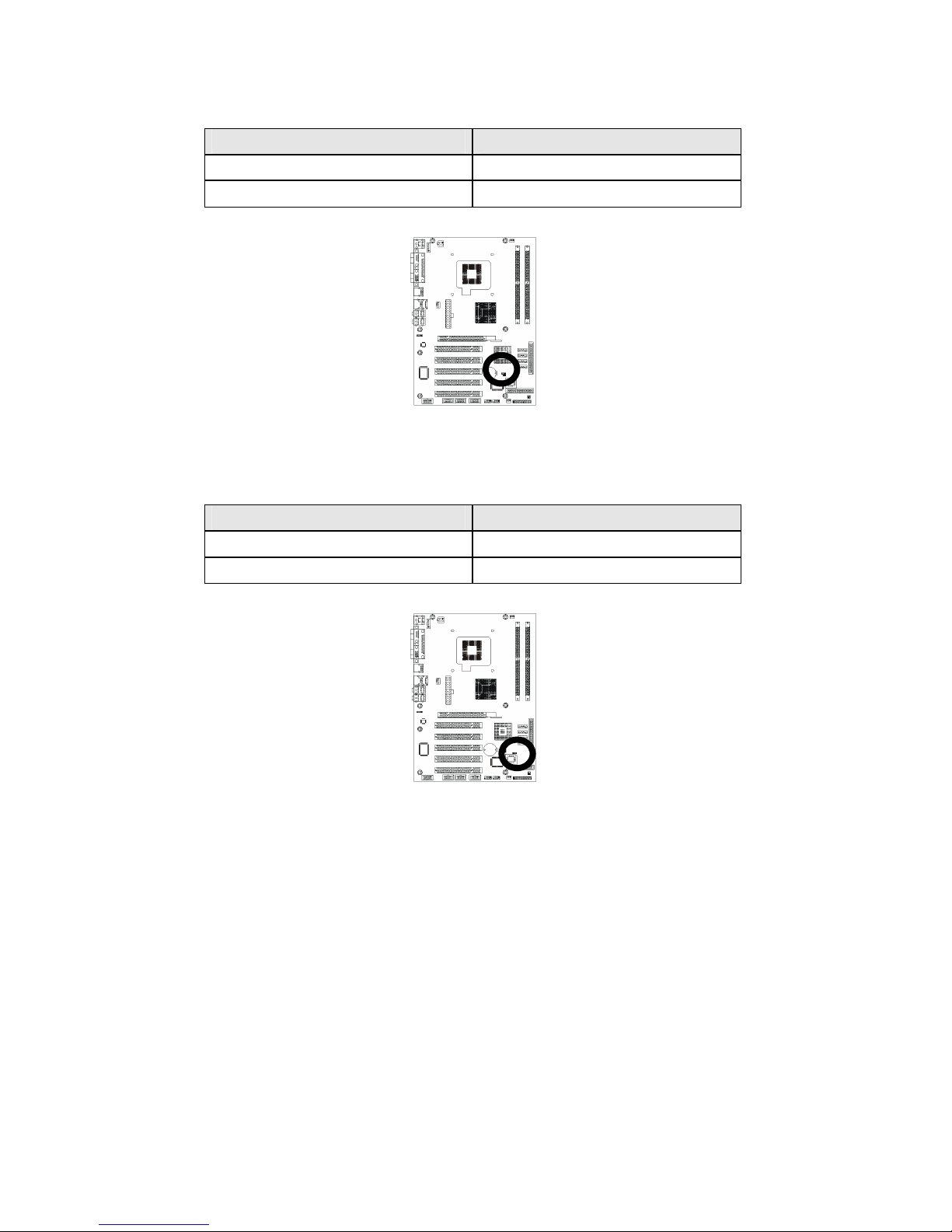
Clear CMOS setting select: JP1
Function JP1
Normal (Default) 1-2
Clear CMOS 2-3
Location:
BIOS write-protect setting select: JP3
Function JP3
BIOS write protection (Default)
1-2
BIOS writable 2-3
Location:
Page 23
Installations
17
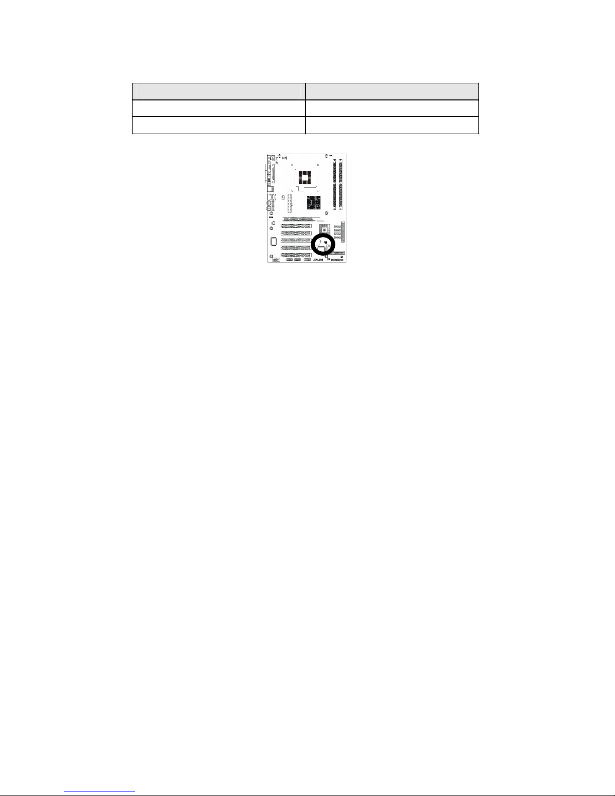
Always power-on setting select: JP4
Function JP4
Always power on
On
Disabled (Default) Off
Location:
Page 24
Installations
18
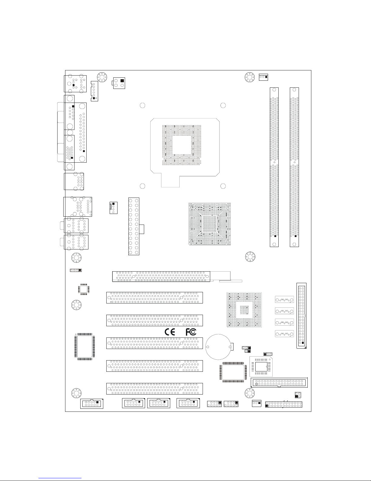
2.4 Connector’s Description
Connector Location
CN6
LGA775
94P16
KB/ MS
CN18
EX T. KB/M S
ATX 12 V
CN17
COM 1
CN2
CN3
LPT
US B 4/ 5
CN1
CRT
CN4
US B 0/1
CN31
LAN & US B 2/3
CN23
CP U FAN
CN12
CN11
CN10
CD- IN
CN25
COM 3COM 2 COM 4
CN26
CN27
US B 6/ 7
CN15
CN32
SY ST EM FAN
CN13
SATA4
FDD
ID E1
SATA3
SATA2
SATA1
DIMM1 DIMM2
CN16
POW ER FAN
CN5
ATX 24 P
PC I- 1
PC I-2
PC I-3
PC I-4
PC I-5
CN30
CN29
CN9
CN8
CN7
BATT1
JP2
LAN-LED
HD_ LED
PWR _O N
RS T SPK R
KB _LOC K
PW_ LE D
IRD A
DIO
CN20
CN21
CN22
JP3
JP4
JP1
PCI-Express 16
CN24
Page 25

Installations
19
Table for Connector’s Location Description:
Use the information in the following table to change the connector.
Connectors Functions
CN1 CRT VGA port connector
CN2 COM1 RS-232 serial port connector
CN3 Parallel port connector
CN4 USB 0/1 connector
CN5 ATX-24pins power connector
CN6 PS/2 keyboard & mouse connectors
CN10 CD_In pin-header
CN11 Audio port phone jack
CN12 Audio port phone jack
CN13 Floppy disk connector
CN15 System fan power connector
CN16 Power fan power connector
CN17 ATX12V-4pins power connector
CN18 External K/B & M/S pin-header
CN20 COM2 RS-232 serial port pin-header
CN21 COM3 RS-232 serial port pin-header
CN22 COM4 RS-232 serial port pin-header
CN23 CPU fan power connector
CN25 8-bit Digital I/O pin-header
CN26 USB 4/5 pin-header
CN27 USB 6/7 pin-header
CN31 Ethernet RJ-45 & USB 2/3 connectors
CN32 System panel indicate pin-header
IDE1 Primary IDE connector
SATA1 / 2 / 3 / 4 SATA1 / 2 / 3 / 4 connectors
JP2 LAN-LED pin-header
Page 26
Installations
20
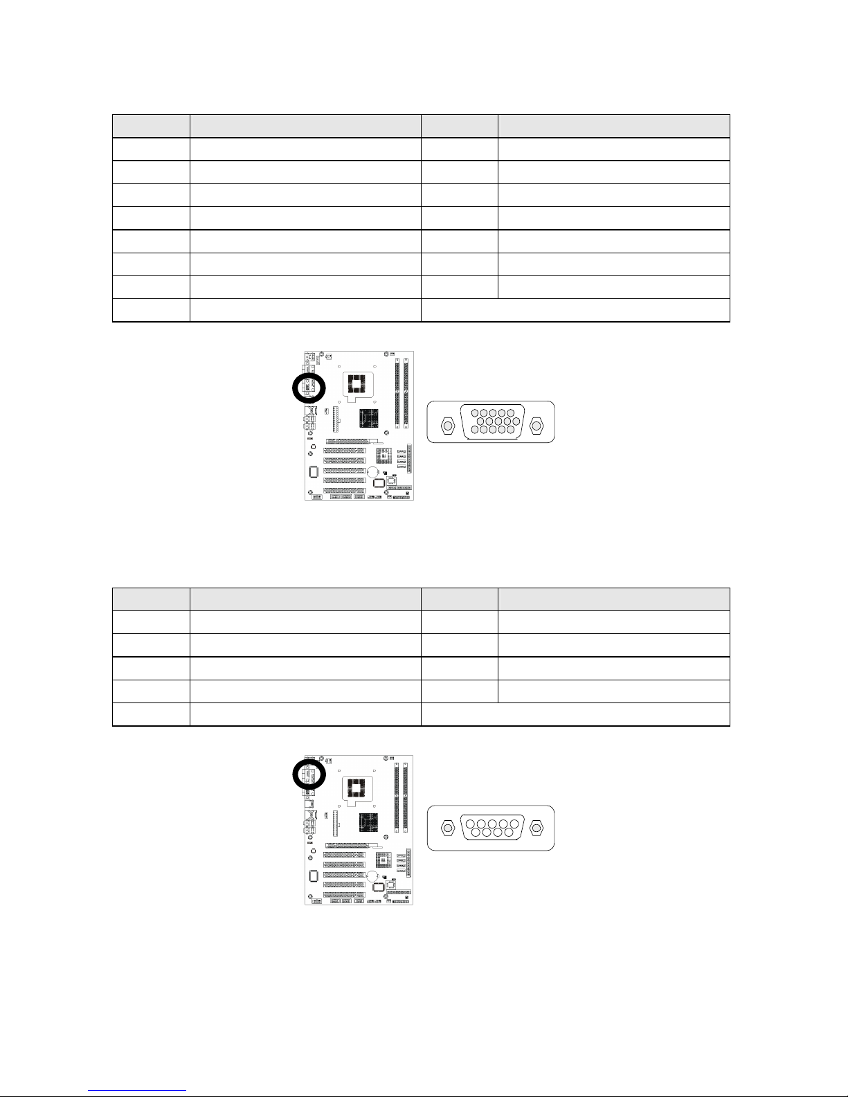
CRT VGA port connector (D-SUB 15-pins female): CN1
Pin #
Assignment Pin #
Assignment
1 Red 2 Green
3 Blue 4 NC
5 Ground 6 Ground
7 Ground 8 Ground
9 VCC 10 Ground
11 NC 12 DData
13 HSync 14 VSync
15 DClk
Figure:
COM1 RS-232 serial port connector (D-Sub 9-pins male): CN2
Pin #
Assignment Pin #
Assignment
1 DCD (Data Carrier Detect)
6 DSR (Data Set Ready)
2 RXD (Receive Data) 7 RTS (Request to Send)
3 TXD (Transmit Data) 8 CTS (Clear to Send)
4 DTR (Data Terminal Ready)
9 RI (Ring Indicator)
5 Ground
Figure:
1
11
5
15
5
9
1
6
Page 27
Installations
21
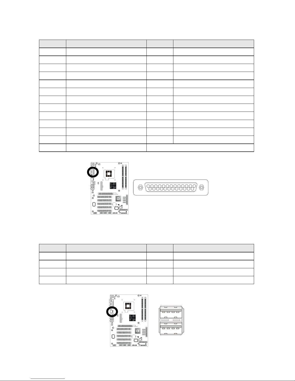
Parallel port connector (D-Sub 25-pins female): CN3
Pin #
Assignment Pin #
Assignment
1 Line Printer Strobe 14 Auto Feed
2 PD 0, Parallel Data 0 15 Error
3 PD 1, Parallel Data 1 16 Initialize
4 PD 2, Parallel Data 2 17 Select
5 PD 3, Parallel Data 3 18 Ground
6 PD 4, Parallel Data 4 19 Ground
7 PD 5, Parallel Data 5 20 Ground
8 PD 6, Parallel Data 6 21 Ground
9 PD 7, Parallel Data 7 22 Ground
10 ACK, Acknowledge 23 Ground
11 Busy 24 Ground
12 Paper Empty 25 Ground
13 Select
Figure:
USB 0/1 connector: CN4
Pin #
Assignment Pin #
Assignment
1a VCC 1b VCC
2a USB0 - 2b USB1 3a USB0 + 3b USB1 +
4a Ground 4b Ground
Figure:
1
14
13
25
1
4
1
4
Page 28
Installations
22
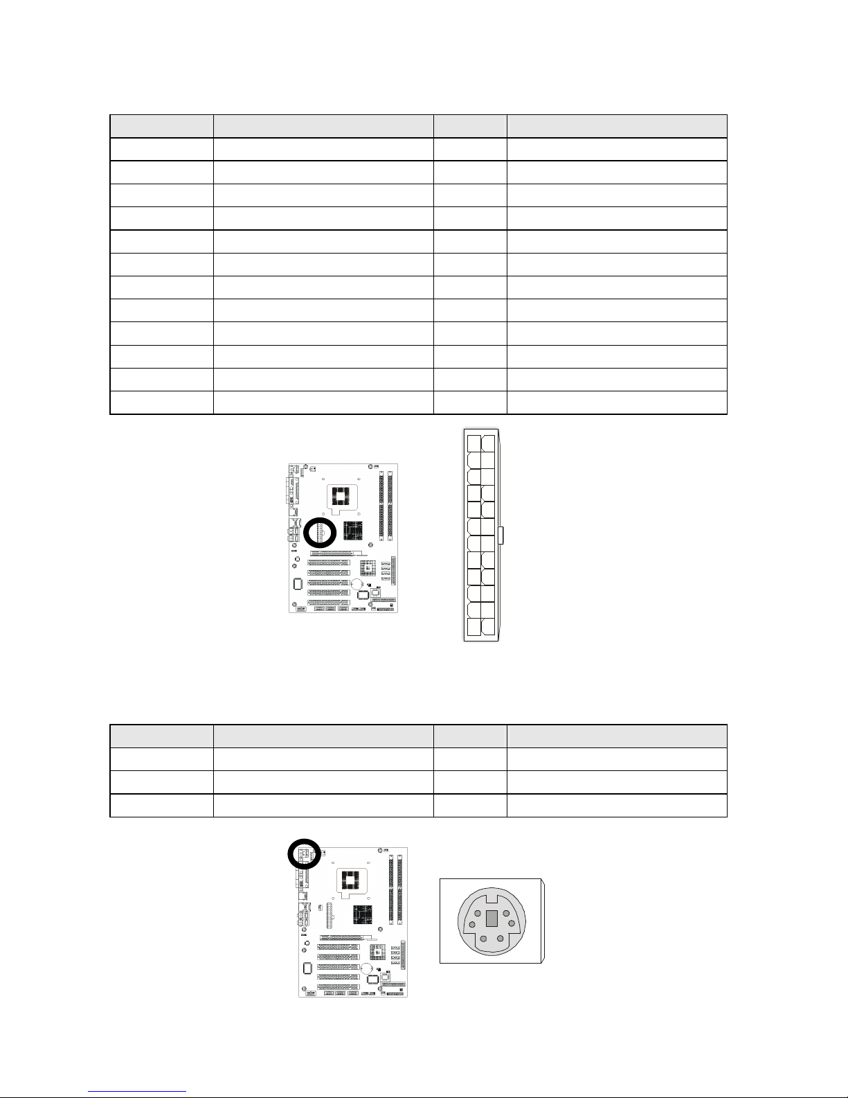
ATX-24pins power connector: CN5
Pin # Assignment Pin #
Assignment
1 +3.3V 13 +3.3V
2 +3.3V 14 -12V
3 Ground 15 Ground
4 +5V 16 PS-ON
5 Ground 17 Ground
6 +5V 18 Ground
7 Ground 19 Ground
8 PWRGD 20 -5V
9 5VSB 21 +5V
10 +12V 22 +5V
11 +12V 23 +5V
12 3.3V 24 Ground
Figure:
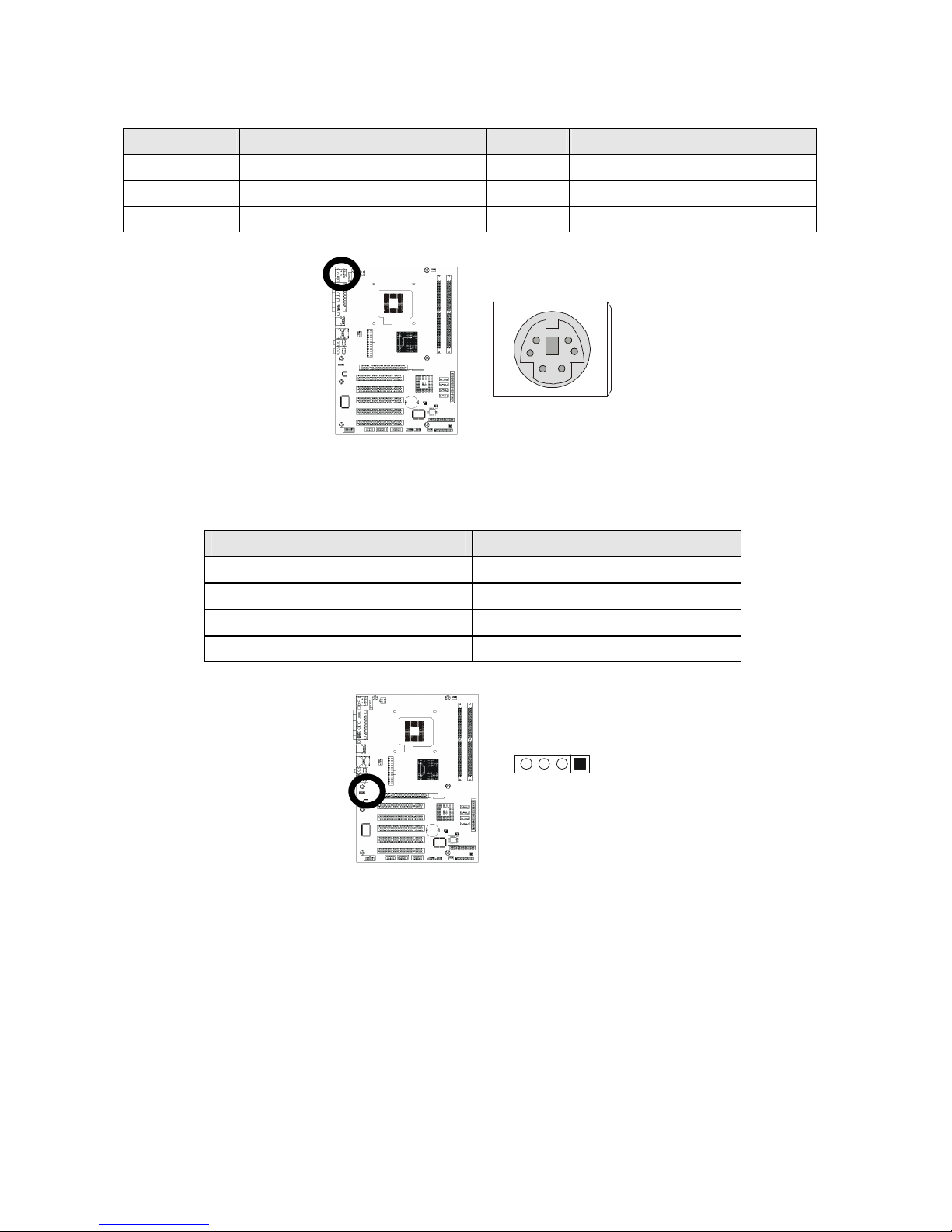
PS/2 keyboard connector (purple Mini Din): CN6
Pin # Assignment Pin #
Assignment
1 Keyboard data 2 NC
3 Ground 4 +5V
5 Keyboard clock 6 NC
Figure:
2
6
1
5
3
4
1
12
24
13
Page 29
Installations
23
PS/2 mouse connector (green Mini Din): CN6
Pin # Assignment Pin #
Assignment
1 Mouse data 2 NC
3 Ground 4 +5V
5 Mouse clock 6 NC
Figure:
CD_In pin-header (4-pins): CN10
Pin # Assignment
1 Left CD_IN
2 Ground
3 Ground
4 Right CD_IN
Figure:
2
6
1
5
3
4
1
4
Page 30
Installations
24
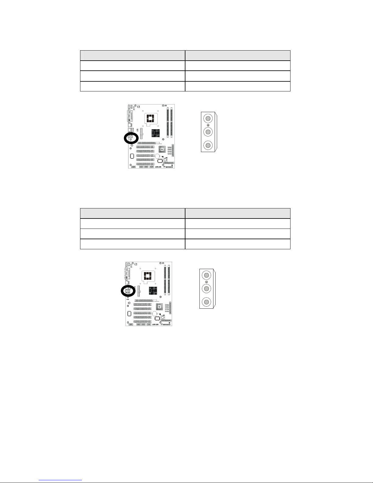
Audio port phone jack: CN11
Pin # Assignment
Blue Line-In
Green Line-Out
Red Mic-In
Figure:
Audio port phone jack: CN12
Pin # Assignment
Orange CEN/LFE_Out
Black SURR_Out
Gray SIDE_Out
Figure:
Blue
Green
Pink
Orange
Black
Gray
Page 31
Installations
25
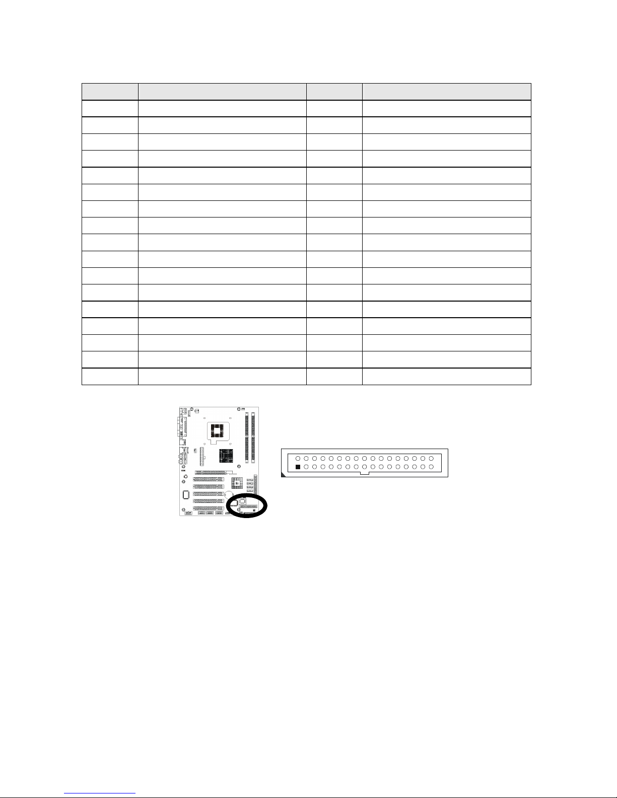
Floppy disk connector (34-pins 2.54mm pitch with housing): CN13
Pin #
Assignment Pin #
Assignment
1 Ground 2 Drive Density Selection
3 Ground 4 NC
5 Ground 6 DSI
7 Ground 8 Index
9 Ground 10 Motor Enable 0
11 Ground 12 DSB
13 Ground 14 Drive Select 0
15 Ground 16 Motor Enable 1
17 Ground 18 Direction
19 Ground 20 Step
21 Ground 22 Write Data
23 Ground 24 Write Gate
25 Ground 26 Track 00
27 Ground 28 Write Protect
29 NC 30 Read Data
31 Ground 32 Side 1 Select
33 NC 34 Diskette Change
Figure:
1
2
34
33
Page 32
Installations
26
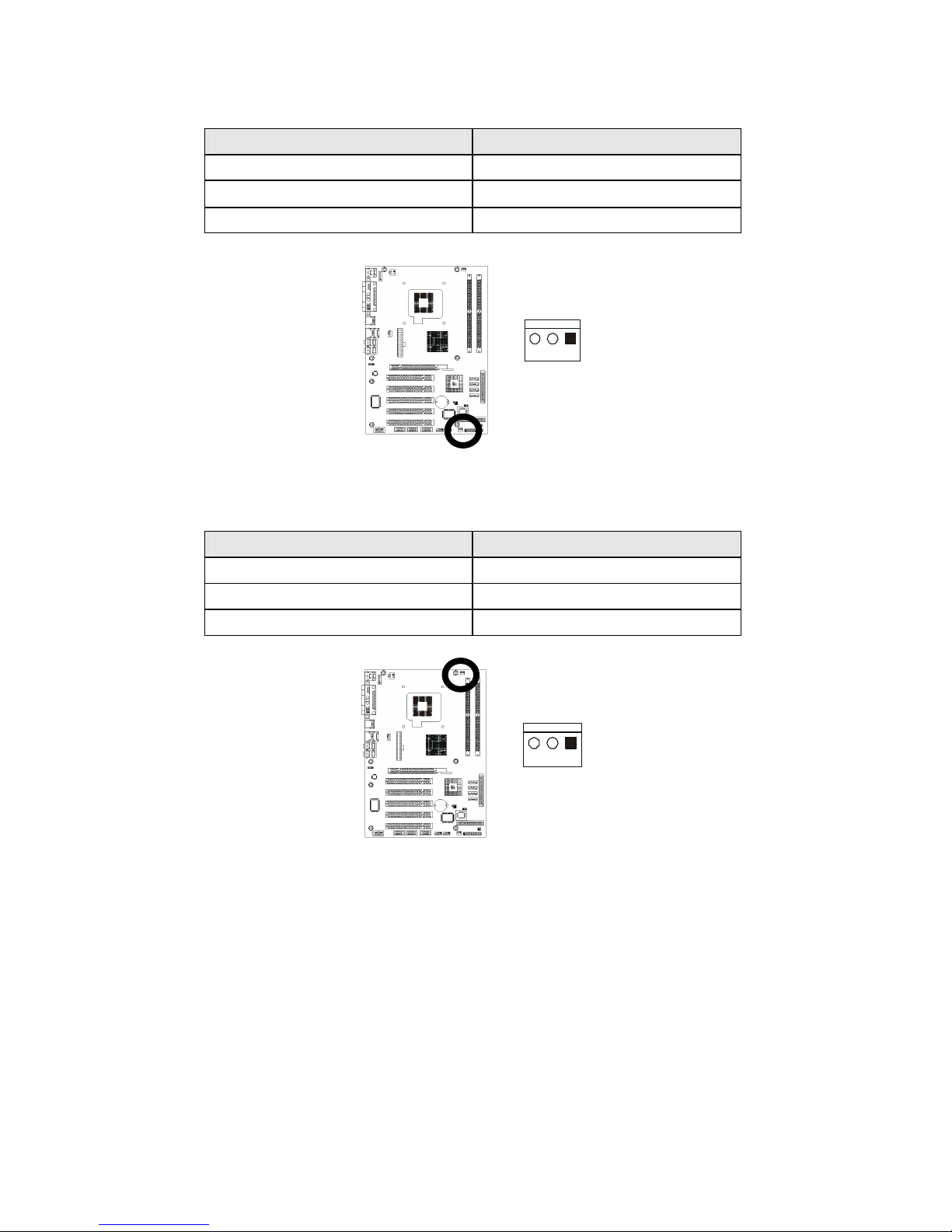
System fan power connector: CN15
Pin # Assignment
1 Ground
2 +12V
3 Fan Status Signal
Figure:
Power fan power connector: CN16
Pin # Assignment
1 Ground
2 +12V
3 Fan Status Signal
Figure:
3 1
3 1
Page 33
Installations
27
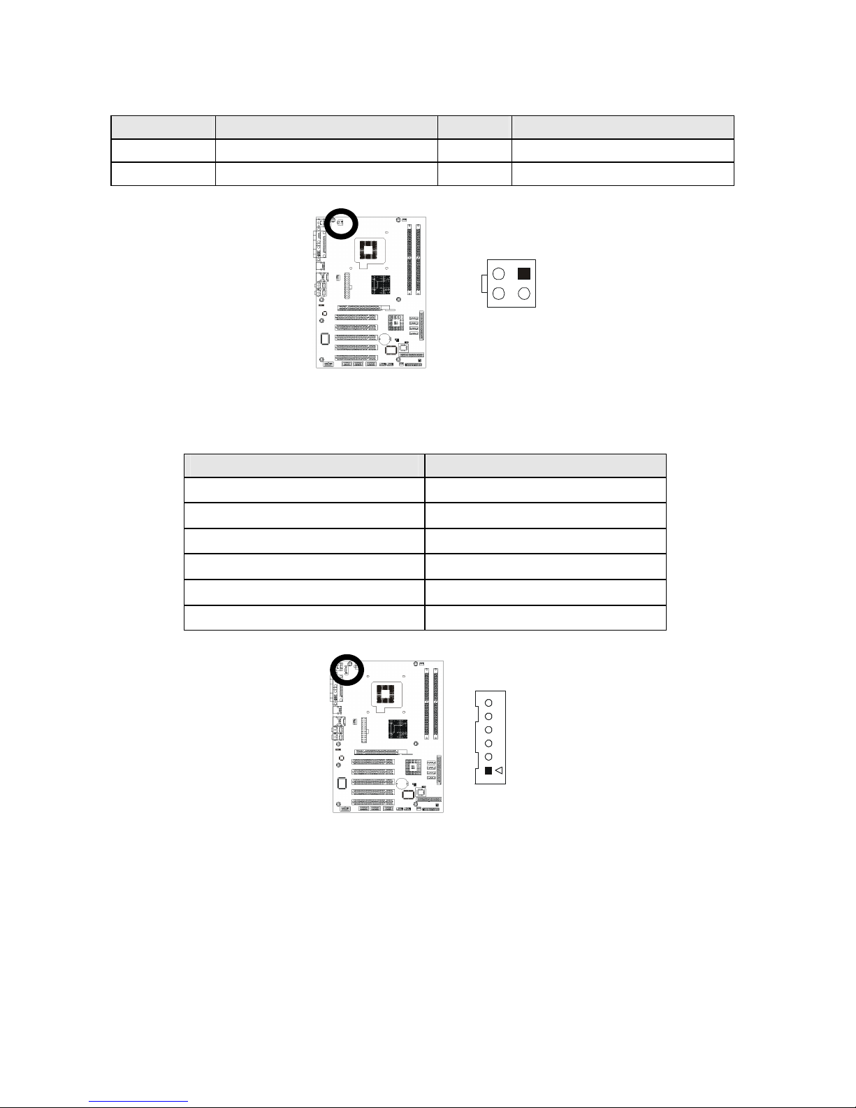
ATX12V-4pins power connector: CN17
Pin # Assignment Pin #
Assignment
1 Ground 3 +12V
2 Ground 4 +12V
Figure:
External K/B & M/S pin-header (6-pins wafer): CN18
Pin # Assignment
1
MS Clock
2
MS Data
3
KB Clock
4
KB Data
5
Ground
6
VCC
Figure:
3 1
4 2
1
6
Page 34
Installations
28
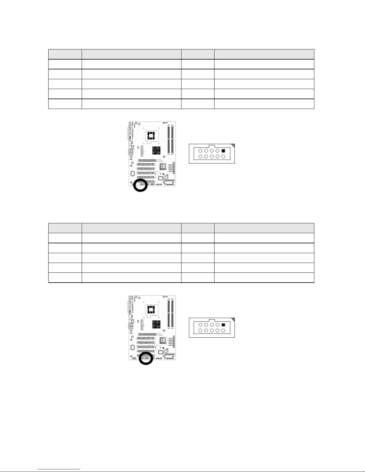
COM2 RS-232 serial port pin-header (10-pins): CN20
Pin #
Assignment Pin #
Assignment
1 DCD 2 DSR
3 RXD 4 RTS
5 TXD 6 CTS
7 DTR 8 RI
9 Ground 10 Ground
Figure:
COM3 RS-232 serial port pin-header (10-pins): CN21
Pin #
Assignment Pin #
Assignment
1 DCD 2 DSR
3 RXD 4 RTS
5 TXD 6 CTS
7 DTR 8 RI
9 Ground 10 Ground
Figure:
2
10
1
9
2
10
1
9
Page 35
Installations
29
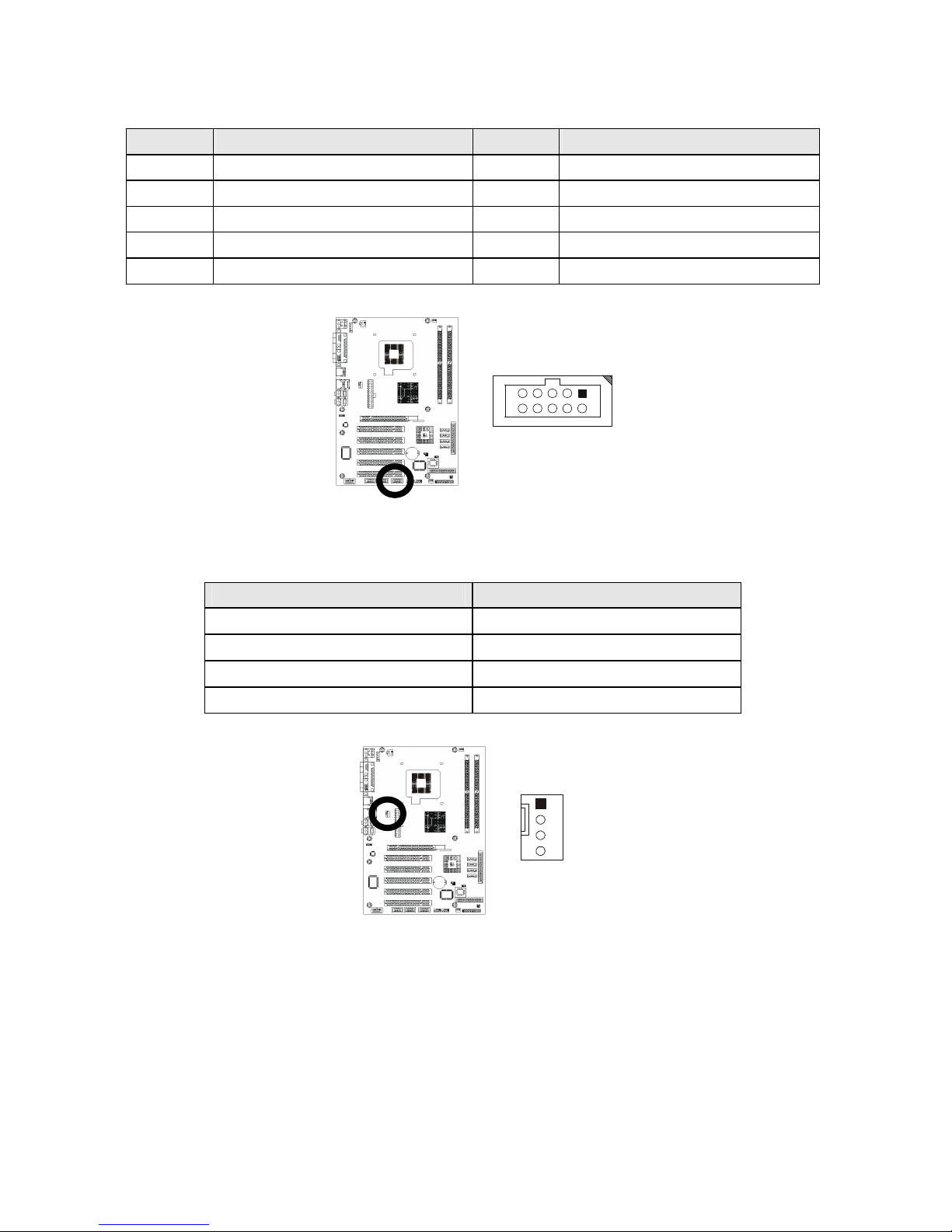
COM4 RS-232 serial port pin-header (10-pins): CN22
Pin #
Assignment Pin #
Assignment
1 DCD 2 DSR
3 RXD 4 RTS
5 TXD 6 CTS
7 DTR 8 RI
9 Ground 10 Ground
Figure:
CPU fan power connector: CN23
Pin # Assignment
1 Ground
2 +12V
3 Fan Status Signal
4 Fanpwm
Figure:
2
10
1
9
4
1
Page 36
Installations
30
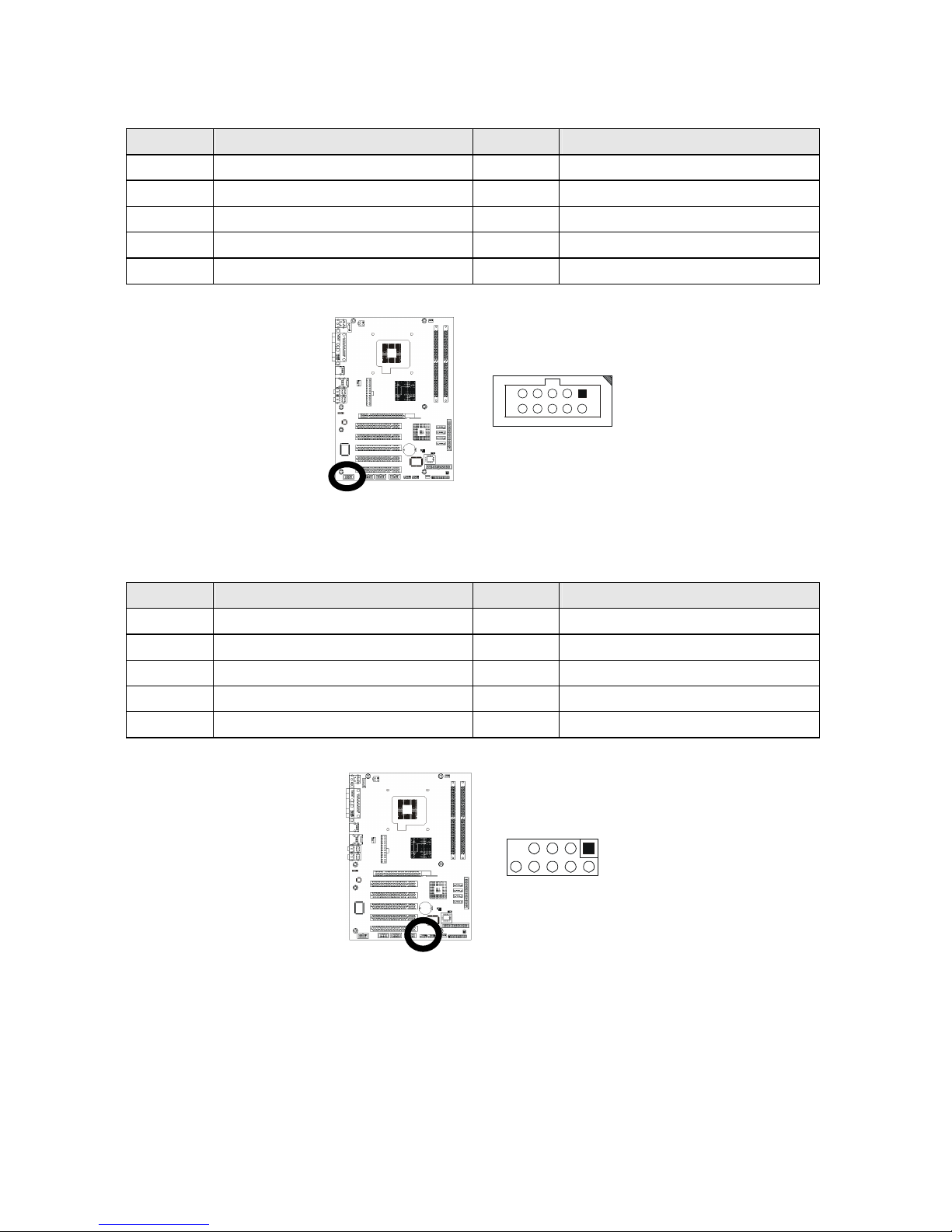
8-bit Digital I/O pin-header (10-pins): CN25
Pin #
Assignment Pin #
Assignment
1 EXT_VDD 2 I1
3 O1 4 I2
5 O2 6 I3
7 O3 8 I4
9 O4 10 EXT_VSS
Figure:
USB 4/5 pin-header (10-pins): CN26
Pin #
Assignment Pin #
Assignment
1 VCC 2 VCC
3 USB4 - 4 USB5 -
5 USB4 + 6 USB5 +
7 Ground 8 Ground
9 --- 10 NC
Figure:
2
10
1
9
9
10
2
1
Page 37
Installations
31
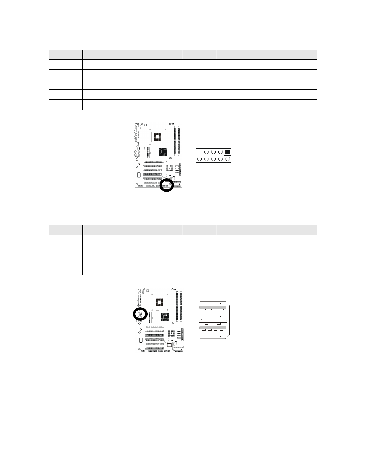
USB 6/7 pin-header (10-pins): CN27
Pin #
Assignment Pin #
Assignment
1 VCC 2 VCC
3 USB6 - 4 USB7 -
5 USB6 + 6 USB7 +
7 Ground 8 Ground
9 --- 10 NC
Figure:
USB 2/3 connector: CN31
Pin #
Assignment Pin #
Assignment
1a VCC 1b VCC
2a USB2 - 2b USB3 3a USB2 + 3b USB3 +
4a Ground 4b Ground
Figure:
9
10
2
1
1
4
1
4
Page 38
Installations
32
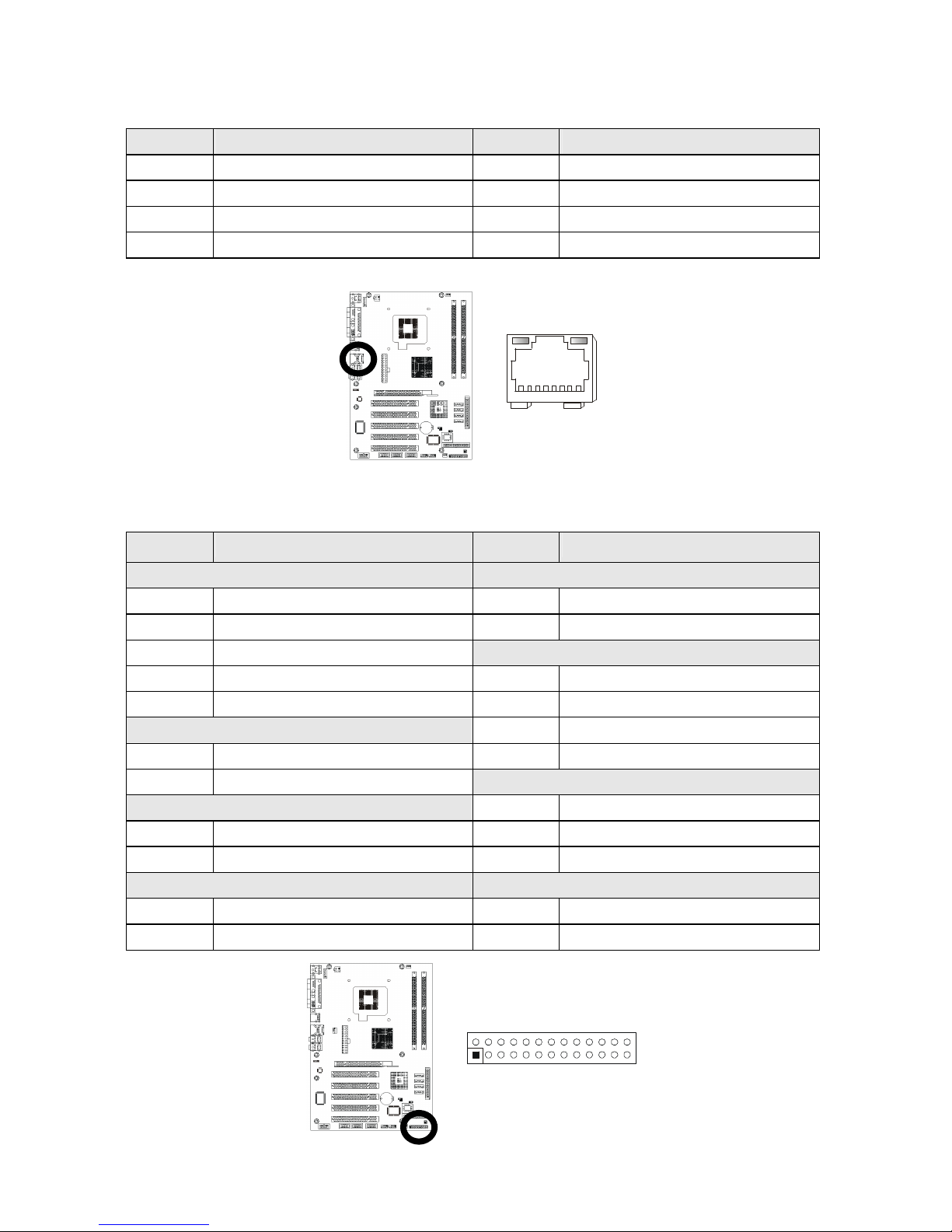
Ethernet RJ-45 connector (RJ-45 phone jack): CN31
Pin #
Assignment Pin #
Assignment
1 Transmit output (+) 5 NC
2 Transmit output (-) 6 Receive input (-)
3 Receive input (+) 7 NC
4 NC 8 NC
Figure:
System panel indicate pin-header: CN32
Pin #
Assignment Pin #
Assignment
IRDA RESET
1 +5V 2 RESET+
3 FIRTX 4 RESET-
5 IRRX
SPEAKER
7 Ground 8 SPEAKER
9 IRTX 10 NC (Buzz)
HDD LED
12 Ground
13 HDLED+ 14 +5V
15 HDLED-
PW_ LED
TB LED
18 PWLED+
17 TBLED+ 20 NC
19 TBLED- 22 PWLED-
PW_ON KB_LOCK
23 PWRBT+ 24 KBLOCK
25 PWRBT- 26 Ground
Figure:
8 1
25
26
2
1
Page 39
Installations
33
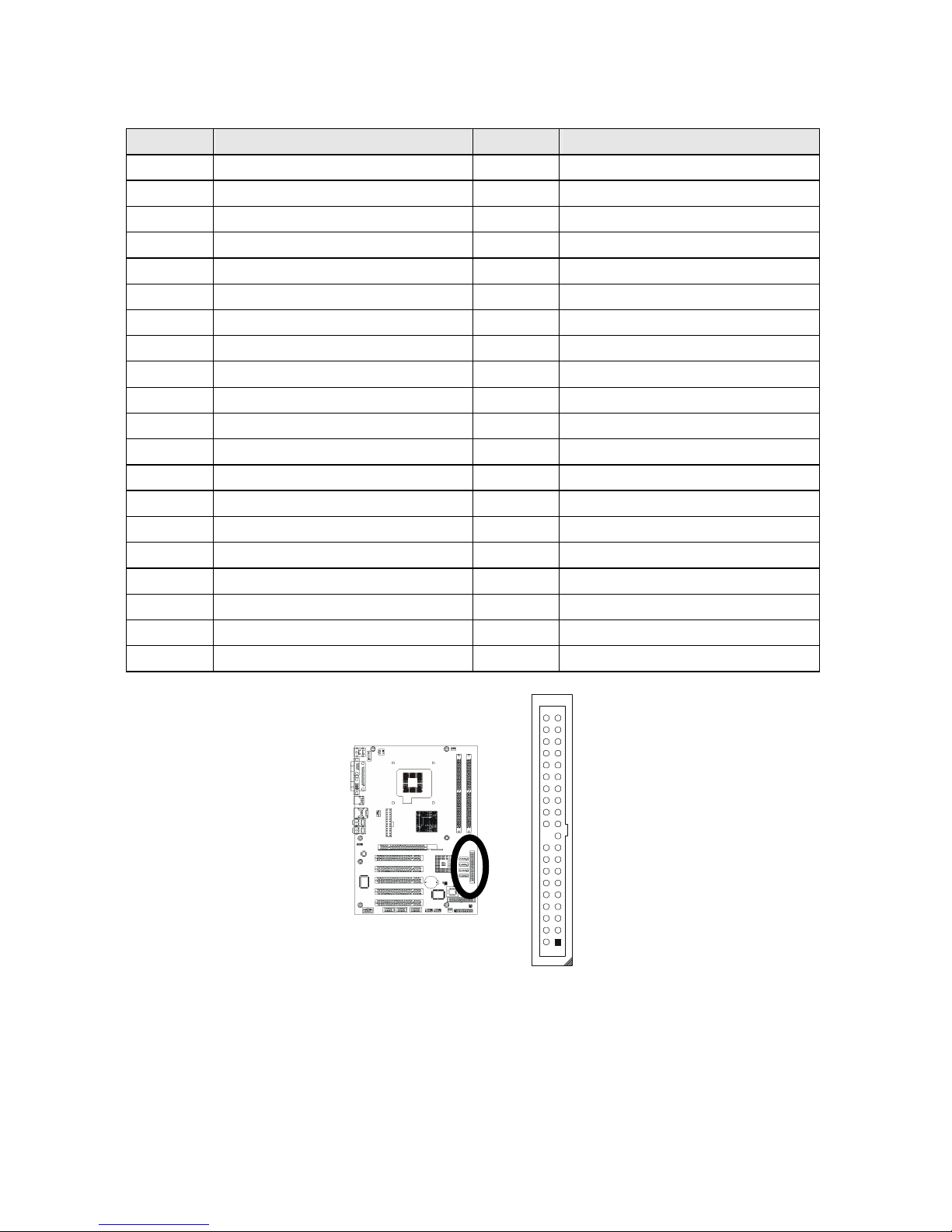
Primary IDE connector (40-pins 2.54mm pitch with housing): IDE1
Pin #
Assignment Pin #
Assignment
1 Reset IDE 2 Ground
3 Host Data 7 4 Host Data 8
5 Host Data 6 6 Host Data 9
7 Host Data 5 8 Host Data 10
9 Host Data 4 10 Host Data 11
11 Host Data 3 12 Host Data 12
13 Host Data 2 14 Host Data 13
15 Host Data 1 16 Host Data 14
17 Host Data 0 18 Host Data 15
19 Ground 20 --21 DRQ 0 22 Ground
23 Host IOW 24 Ground
25 Host IOR 26 Ground
27 IOCHRDY 28 Host ALE
29 DACK 0 30 Ground
31 IRQ 14 32 No Connect
33 Address 1 34 Ground
35 Address 0 36 Address 2
37 Chip Select 0 38 Chip Select 1
39 Activity 40 Ground
Figure:
1
2
40
39
Page 40
Installations
34
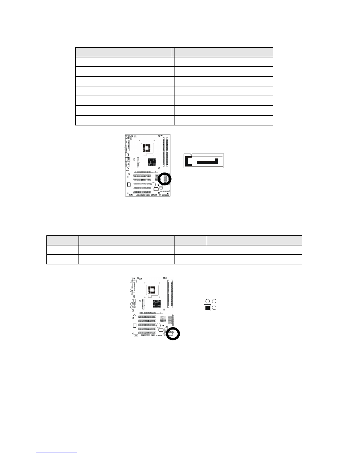
SATA1 / 2 / 3 / 4 connector: SATA1 / 2 / 3 / 4
Pin # Assignment
1 Ground
2 SATA_TX+
3 SATA_TX4 Ground
5 SATA_RX6 SATA_RX+
7 Ground
Figure:
LAN-LED pin-header: JP2
Pin #
Assignment Pin #
Assignment
1 LINK_LED 2 VCC_3V
3 ACT_LED 4 VCC_3V
Figure:
1
7
4
3
1
2
Page 41

35
AWARD BIOS SETUP
3.1 BIOS Instructions
Award’s ROM BIOS provides a built-in Setup program, which allows
user to modify the basic system configuration and hardware parameters.
The modified data will be stored in a battery-backed CMOS, so that data will
be retained even when the power is turned off. In general, the information
saved in the CMOS RAM will stay unchanged unless there is a configuration
change in the system, such as hard drive replacement or a device is added.
It is possible for the CMOS battery to fail, this will cause data loss in the
CMOS only. If this does happen you will need to reconfigure your BIOS
settings.
S
ECTION
3
Page 42

Award BIOS Setup
36
3.2 Main Menu
Once you enter the AwardBIOS™ CMOS Setup Utility, the Main Menu
will appear on the screen. The Main Menu allows you to select from several
setup functions and two exit choices. Use the arrow keys to select among
the items and press <Enter> to accept and enter the sub-menu.
Phoenix - AwardBIOS CMOS Setup Utility
Standard CMOS Feature
Advanced BIOS Feature
Advanced Chipset Feature
Integrated Peripherals
Power Management Setup
PnP/PCI/PCI-E Configurations
PC Health Status
Frequency/Voltage Control
Load Fail-Safe Defaults
Load Optimized Defaults
Set Supervisor Password
Set User Password
Save & Exit Setup
Exit Without Saving
Esc: Quit ↑ ↓ →←: Select Item
F10: Save & Exit Setup
Time, Date, Hard Disk Type….
Note: that a brief description of each highlighted selection appears at the bottom of the screen.
Setup Items:
The main menu includes the following main setup categories. Recall that
some systems may not include all entries.
Standard CMOS Features:
Use this menu for basic system configuration. See section 3.3 for the
details.
Advanced BIOS Features:
Use this menu to set the Advanced Features available on your system. See
section 3.5 for the details.
Advanced Chipset Features:
Use this menu to change the values in the chipset registers and optimize
your system's performance. See section 3.6 for the details.
Page 43

Award BIOS Setup
37
Integrated Peripherals:
Use this menu to specify your settings for integrated peripherals. See
section 3.7 for the details.
Power Management Setup:
Use this menu to specify your settings for power management. See 3.8 for
the details.
PnP / PCI / PCI-E Configuration:
This entry appears if your system supports PnP / PCI / PCI-E. See 3.9 for
the details.
PC Health Status:
Use this menu to show your system temperature, speed and voltage status.
See 3.10 for the details.
Frequency / Voltage Control:
Use this menu to specify your settings for frequency/voltage control. See
3.11 for the details.
Load Fail-Safe Defaults:
Use this menu to load the BIOS default values for the minimal/stable
performance for your system to operate. See 3.12 for the details.
Load Optimized Defaults:
Use this menu to load the BIOS default values that are factory settings for
optimal performance system operations. While Award has designed the
custom BIOS to maximize performance, the factory has the right to change
these defaults to meet their needs. See 3.13 for the details.
Supervisor / User Password:
Use this menu to set User and Supervisor Passwords. See 3.14 for the
details.
Save & Exit Setup:
Save CMOS value changes to CMOS and exit setup. See 3.15 for the
details.
Exit Without Save:
Abandon all CMOS value changes and exit setup. See 3.15 for the details.
Page 44

Award BIOS Setup
38
3.3 Standard CMOS Features
The items in Standard CMOS Setup Menu are divided into 12
categories. Each category includes no, one or more than one setup items.
Use the arrow keys to highlight the item and then use the <PgUp> or
<PgDn> keys to select the value you want in each item.
Standard CMOS Features
Date (mm:dd:yy):
Time (hh:mm:ss):
IDE Channel 0 Master
IDE Channel 0 Slave
IDE Channel 1 Master
IDE Channel 1 Slave
SATA Channel 1
SATA Channel 2
SATA Channel 3
SATA Channel 4
Drive A
Drive B
Video
Halt On
Based Memory
Extended Memory
Total Memory
Mon, May 8 2006
16:19:20
13579 MB
None
None
None
None
None
None
None
1.44M, 3.5 in.
None
EGA/VGA
All, Errors
640K
523264K
524288K
Item Help
____________________________
Menu Level
Change the day, month, year and
century
↑↓→←Move Enter: Select +/-/PU/PD: Value F10: Save ESC: Exit F1: General Help
F5: Previous Values F6: Fail-safe defaults F7: Optimized Defaults
Date: Options Month/DD/YYYY
Set the system date. Note that the ‘Day’ automatically changes when you
set the date.
Time: Options HH : MM : SS
Set the system time.
IDE Channel 0 / 1 Master: Options are in its sub menu (described in 3.4)
Press <Enter> to enter the sub menu of detailed options.
IDE Channel 0 / 1 Slave: Options are in its sub menu (described in 3.4)
Press <Enter> to enter the sub menu of detailed options.
Page 45

Award BIOS Setup
39
SATA Channel 1 / 2 / 3 / 4 : Options are in its sub menu (described in 3.4)
Press <Enter> to enter the sub menu of detailed options.
Drive A / Drive B: Options None 360K, 5.25 in/1.2M, 5.25 in/720K, 3.5 in/
1.44M, 3.5 in/2.88M, 3.5 in
Select the type of floppy disk drive installed in your system.
Video: Options EGA/VGA/CGA 40/CGA 80/MONO
Select the default video device.
Halt On: Options All Errors/No Errors/All, But Keyboard/All, But Diskette/All,
But Disk/Key
Select the situation in which you want the BIOS to stop the POST process
and notify you.
Base Memory:
Displays the amount of conventional memory detected during boot up.
Extended Memory:
Displays the amount of extended memory detected during boot up.
Total Memory:
Displays the total memory available in the system.
Page 46

Award BIOS Setup
40
3.4 IDE Adapters
The IDE adapters control the hard disk drive. Use a separate sub menu
to configure each hard disk drive.
Phoenix - AwardBIOS CMOS Setup Utility
IDE Channel 0 Master
IDE HDD Auto-Detection
IDE Channel 0 Master
Access Mode
Capacity
Cylinder
Head
Precomp
Landing Zone
Sector
Press Enter
Auto
Auto
13579 MB
26310
16
0
26309
63
Item Help
____________________________
Menu Level
To auto-detect the HDD’s size,
head... on this channel
↑↓→←Move Enter: Select +/-/PU/PD: Value F10: Save ESC: Exit F1: General Help
F5: Previous Values F6: Fail-safe defaults F7: Optimized Defaults
IDE HDD Auto-detection: Options Press Enter
Press Enter to auto-detect the HDD on this channel. If detection is
successful, it fills the remaining fields on this menu.
IDE Channel 0 Master: Options None, Auto and Manual
Selecting “Manual” lets you set the remaining fields on this screen. Selects
the type of fixed disk. "User Type" will let you select the number of cylinders,
heads, etc. Note: PRECOMP=65535 means NONE !
Access Mode: Options CHS, LBA, Large and Auto
Choose the access mode for this hard disk
Capacity: Options Auto Display your disk drive size
Disk drive capacity (Approximated). Note that this size is usually slightly
greater than the size of a formatted disk given by a disk-checking program.
Page 47

Award BIOS Setup
41
The following options are selectable only if the ‘IDE Primary Master’
item is set to “Manual”.
Cylinder: Options Min = 0, Max = 65535
Set the number of cylinders for this hard disk.
Head: Options Min = 0, Max = 255
Set the number of read/write heads.
Precomp: Options Min = 0, Max = 65535
**** Warning: Setting a value of 65535 means no hard disk.
Landing Zone: Options Min = 0, Max = 65535
Sector: Options Min = 0, Max = 255
Number of sectors per track
Page 48

Award BIOS Setup
42
3.5 Advanced BIOS Features
This section allows you to configure your system for basic operation.
You have the opportunity to select the system’s default speed, boot-up
sequence, keyboard operation, shadowing and security.
Phoenix - AwardBIOS CMOS Setup Utility
Advanced BIOS Features
CPU Feature
Virus Warning
Hyper-Threading Technology
Quick Power On Self Test
Boot Up NumLock Status
Gate A20 Option
Typematic Rate Setting
X Typematic Rate (Chars/Sec)
X Typematic Delay (Msec)
Security Option
X APIC Mode
MPS Version Control For OS
OS Select For DRAM > 64MB
HDD S.M.A.R.T. Capability
Cache Setup
Boot Seq & Floppy Setup
Press Enter
Disabled
Enabled
Enabled
On
Fast
Disabled
6
250
Steup
Disabled
1.4
Non-OS2
Disabled
Press Enter
Press Enter
Item Help
____________________________
Menu Level
↑↓→←Move Enter: Select +/-/PU/PD: Value F10: Save ESC: Exit F1: General Help
F5: Previous Values F6: Fail-safe defaults F7: Optimized Defaults
CPU Feature:
Phoenix - AwardBIOS CMOS Setup Utility
CPU Feature
Delay Prior to Thermal
Thermal Management
TM2 Bus Ratio
TM2 Bus VID
Limit CPUID MaxVal
C1E Function
Execute Disable Bit
16 Min
Thermal Monitor 2
14X
0.9250V
Disabled
Disabled
Enabled
Item Help
____________________________
Menu Level
↑↓→←Move Enter: Select +/-/PU/PD: Value F10: Save ESC: Exit F1: General Help
F5: Previous Values F6: Fail-safe defaults F7: Optimized Defaults
Delay Prior To Thermal:
Select this item for the delay prior to thermal time.
The Choice: 4, 8, 16, 32 Min.
Page 49

Award BIOS Setup
43
Thermal Management:
This item allows you to manage the thermal monitor
The choice: 1, 2
Limit CPUID MaxVal:
This item allows you to limit CPUID Max value.
The choice: Enabled, Disabled.
C1E Function:
This item allows you to chose mode of C1E Function
The choice: Auto, Disabled.
Execute Disable Bit
This item allows you to execute disable bit.
The choice: Enabled, Disabled.
Virus Warning:
Allow you to choose the VIRUS Warning feature for IDE Hard Disk boot
sector protection. If this function is enabled and someone attempts to write
data into this area, BIOS will show a warning message on screen and alarm
beep.
Enabled---Activates automatically when the system boots up causing a
warning message to appear when anything attempts to
access the boot sector or hard disk partition table.
Disabled---No warning message will appear when anything attempts to
access the boot sector or hard disk partition table.
Hyper-Threading Technology:
This item allows you to enable or disable the CPU Hyper-Threading
Technology.
The choice: Enabled, Disabled.
Quick Power On Self Test:
This category speeds up Power On Self Test (POST) after you power up the
computer. If it is set to Enable, BIOS will shorten or skip some check items
during POST.
Enabled---Enable quick POST
Disabled---Normal POST
Page 50

Award BIOS Setup
44
Boot Up NumLock Status:
Select power on state for NumLock.
The choice: On, Off .
Gate A20 Option:
Select if chipset or keyboard controller should control GateA20.
Normal---A pin in the keyboard controller controls GateA20
Fast---Lets chipset control GateA20
Typematic Rate Setting:
Keystrokes repeat at a rate determined by the keyboard controller. When
enabled, the typematic rate and typematic delay can be selected.
The choice: Enabled, Disabled.
Typematic Rate (Chars/Sec):
Sets the number of times a second to repeat a keystroke when you hold the
key down.
The choice: 6, 8, 10, 12, 15, 20, 24 and 30.
Typematic Delay (Msec):
Sets the delay time after the key is held down before it begins to repeat the
keystroke.
The choice: 250, 500, 750 and 1000.
Security Option:
Select whether the password is required every time the system boots or only
when you enter setup.
System---The system will not boot and access to Setup will be denied if
the correct password is not entered at the prompt.
Setup---The system will boot, but access to Setup will be denied if the
correct password is not entered at the prompt.
Note: To disable security, select PASSWORD SETTING at Main Menu and then you will be
asked to enter password. Do not type anything and just press <Enter>, it will disable security.
Once the security is disabled, the system will boot and you can enter Setup freely.
APIC Mode:
This item allows you to enable or disable APIC Mode.
The choice: Enabled, Disabled.
Page 51

Award BIOS Setup
45
MPS Version Control For OS:
Select the operating system that is Multi-Processors Version Control for OS.
The choice: 1.4, 1.1.
OS Select For DRAM > 64MB:
Select the operating system that is running with greater than 64MB of RAM
on the system.
The choice: Non-OS2, OS2.
HDD S.M.A.R.T. Capability:
This item allows you to enable or disable the HDD self-Monitoring, Analysis,
and Reporting Technology system.
The choice: Enabled, Disabled.
Cache Setup:
Phoenix - AwardBIOS CMOS Setup Utility
Cache Setup
CPU L1 & L2 Cache
Enabled
Item Help
____________________________
Menu Level
↑↓→←Move Enter: Select +/-/PU/PD: Value F10: Save ESC: Exit F1: General Help
F5: Previous Values F6: Fail-safe defaults F7: Optimized Defaults
CPU L1& L2 Cache:
These two categories speed up memory access. However, it depends on
CPU and chipset designed.
The choice: Enabled, Disabled.
Page 52

Award BIOS Setup
46
Boot Seq & Floppy Setup:
Phoenix - AwardBIOS CMOS Setup Utility
Boot Seq & Floppy Setup
Hard Disk Boot Priority
First Boot Device
Second Boot Device
Third Boot Device
Boot Other Device
Swap Floppy Drive
Boot Up Floppy Seek
Report No FDD For WIN95
Press Enabled
Floppy
Hard Disk
LS120
Enabled
Disabled
Enabled
No
Item Help
____________________________
Menu Level
↑↓→←Move Enter: Select +/-/PU/PD: Value F10: Save ESC: Exit F1: General Help
F5: Previous Values F6: Fail-safe defaults F7: Optimized Defaults
Hard Disk Boot Priority:
Press Enter and it shows Bootable add-in Card.
First/Second/Third Boot Device:
The BIOS attempts to load the operating system from the devices in the
sequence selected in these items.
The Choice: Floppy, LS120, HDD, CDROM, ZIP100, USB-FDD,
USB-ZIP, USB-CDROM, LAN, and Disabled.
Boot Other Device:
When enabled, the system searches all other possible locations for an
operating system if it fails to find one in the devices specified under the first,
second, and third boot devices.
The Choice: Enabled, Disabled.
Swap Floppy Drive:
This will swap your physical drive letters A & B if you are using two floppy
disks.
The Choice: Enabled, Disabled.
Boot Up Floppy Seek:
Seeks disk drives during boot up. Disabling speeds boot up.
The choice: Enabled, Disabled.
Report No FDD For WIN95:
Whether report no FDD for Win 95 or not.
The choice: Yes, No.
Page 53

Award BIOS Setup
47
3.6 Advanced Chipset Features
This section allows you to configure the system based on the specific
features of the installed chipset. This chipset manages bus speeds and
access to system memory resources, such as DRAM and the external
cache. It also coordinates communications between the conventional ISA
bus and the PCI bus. It must be stated that these items should never need
to be altered. The default settings have been chosen because they provide
the best operating conditions for your system. The only time you might
consider making any changes would be if you discovered that data was
being lost while using your system.
Phoenix - AwardBIOS CMOS Setup Utility
Advanced Chipset Features
DRAM Timing Selectable
X CAS Latency Time
X DRAM RAS# To CAS# Delay
X DRAM RAS# Precharge
X Precharge dealy (tRAS)
X System Memory Frequency
SLP_S4# Assertion Width
System BIOS Cacheable
Video BIOS Cacheable
Memory Hole At 15M-16M
PCI Express Root Port Function
**VGA Setting **
PEG/Onchip VGA Control
On-Chip Frame Buffer Size
DVMT Mode
DVMT/FIXED Memory Size
Boot Display
By SPD
4
4
4
12
533MHz
1 to 2 Sec.
Enabled
Disabled
Disabled
Press Enter
Auto
8MB
DVMT
128MB
Auto
Item Help
____________________________
Menu Level
↑↓→←Move Enter: Select +/-/PU/PD: Value F10: Save ESC: Exit F1: General Help
F5: Previous Values F6: Fail-safe defaults F7: Optimized Defaults
DRAM Timing Selectable:
Select the operating system that is selecting DRAM timing, so select SPD
for setting SDRAM timing by SPD.
The choice: Manual, By SPD.
CAS Latency Time:
When synchronous DRAM is installed, the number of clock cycles of CAS
latency depends on the DRAM timing.
The choice: Auto, 3, 4 and 5.
Page 54

Award BIOS Setup
48
DRAM RAS# to CAS# Delay:
You can select RAS to CAS Delay time in HCLKs of 2/2, 3/3 or 4/4.
The system board designer should set the values in this field, depending on
the DRAM installed. Do not change the values in this field unless you
change specifications of the installed DRAM or the installed CPU.
The choice: Auto, 2, 3, 4, 5.
DRAM RAS# Precharge:
If an insufficient number of cycles are allowed for the RAS to accumulate its
charge before DRAM refresh, the refresh may be incomplete and the DRAM
may fail to retain data. Fast gives faster performance; and Slow gives more
stable performance. This field applies only when synchronous DRAM is
installed in the system.
The choice: Auto, 2, 3, 4, 5.
Precharge delay (tRAS):
Select the operating system that is active to precharge delay.
The choice: 5~15.
SLP_S4# Assertion Width:
The item allows you to select the assertion width of SLP_S4#
The choice: 4 to 5 Sec, 3 to 4 Sec, 2 to 3 Sec, 1 to 2 Sec
System BIOS Cacheable:
Selecting “Enabled” allows caching of the system BIOS ROM at
F0000h-FFFFFh, resulting in better system performance. However, if any
program writes to this memory area, a system error may result.
The choice: Enabled, Disabled.
Video BIOS Cacheable:
Select “Enabled” allows caching of the video BIOS, resulting in better
system performance. However, if any program writes to this memory area, a
system error may result.
The choice: Enabled, Disabled.
Memory Hole At 15M-16M:
You can reserve this area of system memory for ISA adapter ROM. When
this area is reserved, it cannot be cached. The user information of
peripherals that need to use this area of system memory usually discusses
their memory requirements.
The choice: Enabled, Disabled.
Page 55

Award BIOS Setup
49
PCI Express Root Port Function:
Phoenix - AwardBIOS CMOS Setup Utility
PCI Express Root Port Function
PCI Express Port 1
PCI Express Port 2
PCI-E Compllancy Mode
Auto
Auto
v1.0a
Item Help
____________________________
Menu Level
↑↓→←Move Enter: Select +/-/PU/PD: Value F10: Save ESC: Exit F1: General Help
F5: Previous Values F6: Fail-safe defaults F7: Optimized Defaults
PCI Express Port 1 / 2 :
This item allows you to active PCI Express.
The choice: Auto, Enabled, Disabled.
PCI-E Compliancy Mode:
This item allows you to choose PCI-E Compliancy Mode.
The choice: v1.0a, v1.0.
PEG/Onchip VGA Control:
This item allows you to control the PEG or on-chip VGA.
The choice: Onchip VGA, PEG Port, Auto.
On-Chip Frame Buffer Size:
Select this item allows you to control the on-chip frame buffer size.
The choice: 1MB, 8MB.
DVMT Mode:
This item allows you to select the DVMT mode.
The choice: FIXED, DVMT, BOTH.
DVMT/FIXED Memory Size:
This item allows you to select the DVMT or FIXED memory size.
The choice: 64MB, 128MB.
Boot Display:
Select this item allows you to set the boot display device.
The choice: Auto, CRT, TV, EFP.
Page 56

Award BIOS Setup
50
3.7 Integrated Peripherals
Phoenix - AwardBIOS CMOS Setup Utility
Integrated Peripherals
OnChip IDE Device
Onboard Device
Super I/O Device
Onboard Lan Boot ROM
Onboard Serial Port 3
Serial Port 3 Use IRQ
Onboard Serial Port 4
Serial Port 4 Use IRQ
Press Enter
Press Enter
Press Enter
Disabled
3E8
IRQ10
2F8
IRQ11
Item Help
____________________________
Menu Level
↑↓→←Move Enter: Select +/-/PU/PD: Value F10: Save ESC: Exit F1: General Help
F5: Previous Values F6: Fail-safe defaults F7: Optimized Defaults
OnChip IDE Device:
OnChip IDE Device
IDE HDD Block Mode
IDE DMA transfer access
On-Chip Primary PCI IDE
IDE Primary Master PIO
IDE Primary Slave PIO
IDE Primary Master UDMA
IDE Primary Slave UDMA
On-Chip Secondary PCI IDE
IDE Secondary Master PIO
IDE Secondary Slave PIO
IDE Secondary Master UDMA
IDE Secondary Slave UDMA
**On-Chip Serial ATA Setting**
SATA Mode
On-Chip Serial ATA
SATA Port Speed Settings
X PATA IDE Mode
SATA Port
Enabled
Enabled
Enabled
Auto
Auto
Auto
Auto
Enabled
Auto
Auto
Auto
Auto
IDE
Enhanced Mode
Disabled
Primary
SATA2/4 is Secondary
Item Help
____________________________
Menu Level
If you IDE hard drive supports block
mode select Enabled for automatic
detection of the optimal number of
block read/writes per sector the
drive can support.
↑↓→←Move Enter: Select +/-/PU/PD: Value F10: Save ESC: Exit F1: General Help
F5: Previous Values F6: Fail-safe defaults F7: Optimized Defaults
IDE HDD Block Mode:
Block mode is also called block transfer, multiple commands, or multiple
sector read/write. If your IDE hard drive supports block mode (most new
drives do), select Enabled for automatic detection of the optimal number of
block read/writes per sector the drive can support.
The choice: Enabled, Disabled.
Page 57

Award BIOS Setup
51
IDE DMA transfer access:
This item allows you to enable or disable IDE DMA transfer access.
The choice: Enabled, Disabled.
OnChip Primary/Secondary PCI IDE:
The integrated peripheral controller contains an IDE interface with support
for two IDE channels. Select “Enabled” to activate each channel separately.
The choice: Enabled, Disabled.
IDE Primary/Secondary Master/Slave PIO:
The four IDE PIO (Programmed Input/Output) fields let you set a PIO mode
(0-4) for each of the four IDE devices that the onboard IDE interface
supports. Modes 0 through 4 provide successively increased performance.
In Auto mode, the system automatically determines the best mode for each
device.
The choice: Auto, Mode 0, Mode 1, Mode 2, Mode 3 and Mode 4.
IDE Primary/Secondary Master/Slave UDMA:
Ultra DMA/33 implementation is possible only if your IDE hard drive
supports it and the operating environment includes a DMA driver (Windows
95 OSR2 or a third-party IDE bus master driver). If your hard drive and your
system software both support Ultra DMA/33, select “Auto” to enable BIOS
support.
The choice: Auto, Disabled.
On-Chip Serial ATA:
There are five Serial ATA fields let you set the Serial ATA.
The choice: Disabled---Disabled SATA Controller.
Auto---Auto arrange by BIOS.
SATA Only---SATA is operating in legacy mode.
Combined Mode---PATA and SATA are combined. Max. of
2 IDE drives in each channel.
Enhanced Mode---Enable both SATA and PATA. Max. of
6 IDE drives are supported.
SATA Ports Speed Settings:
This item allows you set the SATA Ports Speed.
The choice: Disabled, Force GEN I, Force GEN II.
Page 58

Award BIOS Setup
52
Onboard Device:
Phoenix - AwardBIOS CMOS Setup Utility
Onboard Device
USB Controller
USB 2.0 Controller
USB Keyboard Support
USB Mouse Support
Azalia/AC97 Audio Select
Onboard LAN Control
Enabled
Enabled
Disabled
Disabled
Auto
Enabled
Item Help
____________________________
Menu Level
↑↓→←Move Enter: Select +/-/PU/PD: Value F10: Save ESC: Exit F1: General Help
F5: Previous Values F6: Fail-safe defaults F7: Optimized Defaults
USB Controller:
Select “Enabled” if your system contains a Universal Serial Bus (USB)
controller and you have USB peripherals.
The choice: Enabled, Disabled.
USB 2.0 Controller:
Select “Enabled” if your system contains a Universal Serial Bus 2.0 (USB
2.0) controller and you have USB peripherals.
The choice: Enabled, Disabled.
USB Keyboard Support:
Select “Enabled” if your system contains a Universal Serial Bus (USB)
controller and you have a USB keyboard.
The choice: Enabled, Disabled.
USB Mouse Support:
Select “Enabled” if your system contains a Universal Serial Bus (USB)
controller and you have a USB mouse.
The choice: Enabled, Disabled.
Azalia/AC97 Audio Select
This item allows you to select the chipset family to support AC97 Audio.
The choice: Auto, Azalia, AC97 Audio and Modem, AC97 Audio only,
AC97 Modem only, All disabled
Page 59

Award BIOS Setup
53
Onboard Lan Boot ROM:
This item allows you to enable or disable the onboard LAN Boot ROM.
The choice: Enabled, Disabled.
Onboard I/O Chip Setup:
Phoenix - AwardBIOS CMOS Setup Utility
Onboard I/O Chip Setup
Power ON Function
X KB Power ON Password
X Hot Key Power ON
Onboard FDC Controller
Onboard Serial Port 1
Onboard Serial Port 2
UART Mode Select
X UR2 Duplex Mode
Onboard Parallel Port
Parallel Port Mode
X ECP Mode Use DMA
PWRON After PWR-Fail
BUTTON ON
Enter
Ctrl-F1
Enabled
3F8/IRQ4
2F8/IRQ3
Normal
Half
378/IRQ7
SPP
3
Off
Item Help
____________________________
Menu Level
↑↓→←Move Enter: Select +/-/PU/PD: Value F10: Save ESC: Exit F1: General Help
F5: Previous Values F6: Fail-safe defaults F7: Optimized Defaults
Power On Function:
You can use this item to select operating Power On the system.
The choice: Button Only, Hot Key, Mouse Move, Mouse Click, Any key,
Button Only, Keyboard98.
KB Power ON Password:
You can use this item to limit operating KB Power On system.
The choice: Enter.
Hot Key Power ON:
You can use this item to select operating Hot Key to Power On system.
The choice: Ctrl-F1~Ctrl-F12.
Page 60

Award BIOS Setup
54
Onboard FDC Controller:
Select “Enabled” if your system has a floppy disk controller (FDC) installed
on the system board and you wish to use it. If you install and-in FDC or the
system has no floppy drive, select Disabled in this field.
The choice: Enabled, Disabled.
Onboard Serial Port 1/Port 2:
Select an address and corresponding interrupt for the first and second serial
ports.
The choice: 3F8/IRQ4, 2E8/IRQ3, 3E8/IRQ4, 2F8/IRQ3, Disabled and
Auto.
UART Mode Select:
This item allows you to determine which Infra Red (IR) function of onboard
I/O chip.
The Choice: Normal, IrDA, ASKIR, and SCR.
UR2 Duplex Mode:
This item allows you to select the IR half/full duplex function.
The choice: Half, Full.
Onboard Parallel Port:
This item allows you to determine access onboard parallel port controller
with which I/O address.
The choice: 3BC/IRQ7, 378/IRQ7, 278/IRQ5 and Disabled.
Parallel Port Mode:
Select an operating mode for the onboard parallel (printer) port. Select
Normal, Compatible, or SPP unless you are certain your hardware and
software both support one of the other available modes.
The choice: SPP, EPP, ECP and ECP+EPP.
ECP Mode Use DMA:
Select a DMA channel for the parallel port for use during ECP mode.
The choice: 3, 1.
PWRON After PWR-Fail:
This item allows you to select if you want to power on the system after power
failure.
The choice: Off, On and Former-Sts.
Page 61

Award BIOS Setup
55
Onboard LAN boot ROM
This item allows you to enable or disable the onboard LAN Boot ROM.
The choice: Enabled, Disabled.
Onboard Serial Port 3 / 4 :
Select an address for the third and fourth serial ports.
The choice: 3F8, 2F8, 3E8, 2E8, Disable.
Serial Port 3 / 4 Use IRQ:
Select a corresponding interrupt the third and fourth serial ports.
The choice: IRQ10, IRQ11, IRQ3, IRQ4.
Page 62

Award BIOS Setup
56
3.8 Power Management Setup
The Power Management Setup allows you to configure your system to
most effectively save energy while operating in a manner consistent with
your own style of computer use.
Phoenix - AwardBIOS CMOS Setup Utility
Power Management Setup
ACPI Function
Power Management
Video Off Method
Video Off In Suspend
Suspend Type
MODEM Use IRQ
Suspend Mode
HDD Power Down
Soft-Off by PWR-BTTN
CPU THRM-Throttling
Wake-Up by PCI card
Power On by Ring
Resume by Alarm
X Date (of Month) Alarm
X Time (hh:mm:ss) Alarm
**Reload Global Timer Events**
Primary IDE 0
Primary IDE 1
Enabled
User Define
DPMS
YES
Stop Grant
3
Disabled
Disabled
Instant-Off
50.0%
Disabled
Disabled
Disabled
0
0:0:0
Disabled
Disabled
Item Help
____________________________
Menu Level
↑↓→←Move Enter: Select +/-/PU/PD: Value F10: Save ESC: Exit F1: General Help
F5: Previous Values F6: Fail-safe defaults F7: Optimized Defaults
ACPI Function:
This item allows you to enable/disable the Advanced Configuration and
Power Management (ACPI).
The choice: Enabled, Disabled.
Power Management:
This category allows you to select the type (or degree) of power saving and
is directly related to the following modes:
1. HDD Power Down
2. Doze Mode
Suspend Mode
Page 63

Award BIOS Setup
57
Min. Power Saving:
Minimum power management. Doze Mode = 1 hr. Standby Mode = 1
hr., Suspend Mode = 1 hr., and HDD Power Down = 15 min.
Max. Power Saving:
Maximum power management -- ONLY AVAILABLE FOR SL CPU’s.
Doze Mode = 1 min., Standby Mode = 1 min., Suspend Mode = 1 min.,
and HDD Power Down = 1 min.
User Defined:
Allow you to set each mode individually. When not disabled, each of
the ranges is from 1 min. to 1 hr. except for HDD Power Down, which
ranges from 1 min. to 15 min. and disable.
Video Off Method:
This determines the manner in which the monitor is blanked.
V/H SYNC+Blank:
This selection will cause the system to turn off the vertical and
horizontal synchronization ports and write blanks to the video buffer.
Blank Screen:
This option only writes blanks to the video buffer.
DPMS:
Initial display power management signaling.
Video Off In Suspend:
This determines the manner in which the monitor is blanked.
The choice: Yes, No.
Suspend Type:
Select the Suspend Type.
The choice: PwrOn Suspend, Stop Grant.
Page 64

Award BIOS Setup
58
MODEM Use IRQ:
This determines the IRQ in which the MODEM can use.
The choice: 3, 4, 5, 7, 9, 10, 11 and NA.
Suspend Mode:
When “Enabled” and after the set time of system inactivity. All devices
except the CPU will be shut off.
The choice: Disabled, 1, 2, 4, 8, 12, 20, 30, 40 Min and 1Hour.
HDD Power Down:
When “Enabled” and after the set time of system inactivity, the hard disk
drive will be powered down while all other devices remain active.
The choice: Disabled, 1~15Min.
Soft-Off by PWR-BTTN:
Pressing the power button for more than 4 seconds forces the system to
enter the Soft-Off state when the system has “hung.”
The choice: Delay 4 Sec, Instant-Off.
CPU THRM-Throttling:
Select the CPU THRM-Throttling rate.
The choice: 25.0%, 50.0%, 75.0%.
Wake-Up by PCI card:
An input signal from PME on the PCI card awakens the system from a soft
off state
The choice: Enabled, Disabled.
Power On by Ring:
An input signal on the serial Ring Indicator (RI) line (in other words, an
incoming call on the modem) awakens the system from a soft off state.
The choice: Enabled, Disabled.
Resume by Alarm:
When “Enabled”, your can set the date and time at which the RTC (real-time
clock) alarm awakens the system from Suspend mode.
The choice: Enabled, Disabled.
Page 65

Award BIOS Setup
59
Reload Global Timer Events:
The events are I/O events whose occurrence can prevent the system from
entering a power saving mode or can awaken the system from such a mode.
In effect, the system remains alert for anything, which occurs to a device,
which is configured as Enabled, even when the system is in a power down
mode.
Primary IDE 0
Primary IDE 1
Secondary IDE 0
Secondary IDE 1
FDD, COM, LPT Port
PCI PIRQ [A-D] #
Page 66

Award BIOS Setup
60
3.9 PnP/PCI/PCI-E Configurations
This section describes configuring the PCI bus system. PCI, or
Personal Computer Interconnect, is a system, which allows I/O devices to
operate at speeds nearing the speed the CPU itself uses when
communicating with its own special components. This section covers some
very technical items and it is strongly recommended that only experienced
users should make any changes to the default settings.
Phoenix - AwardBIOS CMOS Setup Utility
PnP/PCI Configurations
Init Display First
Reset Configuration Data
Resources Controlled By
X IRQ Resources
PCI/VGA Palette Snoop
** PCI Express relative items **
Maximum Payload Size
PCI Slot
Disabled
Auto (ESCD)
Press Enter
Disabled
4096
Item Help
_________________________
Menu Level
↑↓→←Move Enter: Select +/-/PU/PD: Value F10: Save ESC: Exit F1: General Help
F5: Previous Values F6: Fail-safe defaults F7: Optimized Defaults
Init Display First:
This item is used to select whether to initialize the PCI slot or on-chip VGA
first when the system boots
The choice: PCI Slot, Onboard.
Reset Configuration Data:
Normally, you leave this field Disabled. Select Enabled to reset Extended
System Configuration Data (ESCD) when you exit Setup if you have
installed a new add-on and the system reconfiguration has caused such a
serious conflict that the operating system cannot boot.
The choice: Enabled, Disabled.
Page 67

Award BIOS Setup
61
Resources Controlled By:
It allows you can automatically configure all the boot and Plug and
Play-compatible devices. If you select Auto, all the interrupt request (IRQ)
and DMA assignment fields disappear, as the BIOS automatically assigns
them.
The choice: Auto (ESCD), Manual.
IRQ Resources:
Phoenix - AwardBIOS CMOS Setup Utility
IRQ Resources
IRQ3 assigned to
IRQ4 assigned to
IRQ5 assigned to
IRQ7 assigned to
IRQ9 assigned to
IRQ10 assigned to
IRQ11 assigned to
IRQ12 assigned to
IRQ14 assigned to
IRQ15 assigned to
PCI Device
PCI Device
PCI Device
PCI Device
PCI Device
PCI Device
PCI Device
PCI Device
PCI Device
PCI Device
Item Help
____________________________
Menu Level
↑↓→←Move Enter: Select +/-/PU/PD: Value F10: Save ESC: Exit F1: General Help
F5: Previous Values F6: Fail-safe defaults F7: Optimized Defaults
IRQs:
When resources are controlled manually, assign each system interrupt a
type, depending on the type of device using the interrupt.
The choice: PCI Device, Reserved.
PCI/VGA Palette Snoop:
Leave this field at “Disabled”.
The choice: Enabled, Disabled.
Maximum Payload Size:
Set maximum TLP playload size for the PCI Express devices. The unit is
byte.
The choice: 128, 256, 512, 1024, 2048, 4096.
Page 68

Award BIOS Setup
62
3.10 PC Health Status
Phoenix - AwardBIOS CMOS Setup Utility
PC Health Status
Shutdown Temperature
VDIMM
Vcore
3.3V
5V
12V
Voltage Battery
SYS Temperature
CPU Temperature
CPU FAN Speed
SYS FAN Speed
Power FAN Speed
Disabled
1.80V
1.31V
3.36V
5.05V
11.71V
3.04V
34°C
47°C
0 RPM
0 RPM
6750 RPM
Item Help
____________________________
Menu Level
↑↓→←Move Enter: Select +/-/PU/PD: Value F10: Save ESC: Exit F1: General Help
F5: Previous Values F6: Fail-safe defaults F7: Optimized Defaults
Shutdown Temperature:
This item allows you to set up the CPU shutdown Temperature.
The choice: Disabled, 60°C / 140°F, 65°C / 149°F, 70°C / 158°F.
VDIMM:
The voltage level of the DRAM.
Vcore:
The voltage level of CPU (Vcore).
+3.3V/+5V/+12V:
Show you the voltage of +3.3V/+5V/+12V.
Voltage Battery:
Show you the voltage level of the battery.
SYS/CPU Temperature:
Show you the current system/CPU temperature.
CPU/SYS/Power FAN Speed:
Show you the current CPU/SYS/Power FAN operating speed.
Page 69

Award BIOS Setup
63
3.11 Frequency/Voltage Control
Phoenix - AwardBIOS CMOS Setup Utility
Frequency/Voltage Control
Auto Detect PCI Clk
Spread Spectrum
Disabled
Disabled
Item Help
____________________________
Menu Level
↑↓→←Move Enter: Select +/-/PU/PD: Value F10: Save ESC: Exit F1: General Help
F5: Previous Values F6: Fail-safe defaults F7: Optimized Defaults
Auto Detect PCI CLK:
When “Enabled”, this item will auto detect if the PCI socket have devices
and will send clock signal to PCI devices. When disabled, it will send the
clock signal to all PCI socket.
The choice: Enabled, Disabled.
Spread Spectrum:
This item allows you to set the spread spectrum modulated.
The choice: Enabled, Disabled.
Page 70

Award BIOS Setup
64
3.12 Load Fail-Safe Defaults
When you press <Enter> on this item you get a confirmation dialog box
with a message similar to:
Load Fail-Safe Defaults (Y/N)? N
Pressing ‘Y’ loads the BIOS default values for the most stable,
minimal-performance system operations.
3.13 Load Optimized Defaults
When you press <Enter> on this item you get a confirmation dialog box
with a message similar to:
Load Optimized Defaults (Y/N)? N
Pressing ‘Y’ loads the default values that are factory settings for optimal
performance system operations.
Page 71

Award BIOS Setup
3.14 Supervisor/User Password Setting
You can set either supervisor or user password, or both of then. The
differences between are:
Set Supervisor Password: can enter and change the options of the setup
menus.
Set User Password: just can only enter but do not have the right to change
the options of the setup menus. When you select this function, the following
message will appear at the center of the screen to assist you in creating a
password.
ENTER PASSWORD:
Type the password, up to eight characters in length, and press <Enter>.
The password typed now will clear any previously entered password from
CMOS memory. You will be asked to confirm the password. Type the
password again and press <Enter>. You may also press <Esc> to abort the
selection and not enter a password.
To disable a password, just press <Enter> when you are prompted to
enter the password. A message will confirm the password will be disabled.
Once the password is disabled, the system will boot and you can enter
Setup freely.
PASSWORD DISABLED.
When a password has been enabled, you will be prompted to enter it
every time you try to enter Setup. This prevents an unauthorized person
from changing any part of your system configuration.
Additionally, when a password is enabled, you can also require the
BIOS to request a password every time your system is rebooted. This would
prevent unauthorized use of your computer.
You determine when the password is required within the BIOS Features
Setup Menu and its Security option (see Section 3). If the Security option is
set to “System”, the password will be required both at boot and at entry to
Setup. If set to “Setup”, prompting only occurs when trying to enter Setup.
Page 72

Award BIOS Setup
66
3.15 Exit Selecting
Save & Exit Setup
Pressing <Enter> on this item asks for confirmation:
Save to CMOS and EXIT (Y/N)? Y
Pressing “Y” stores the selections made in the menus in CMOS – a
special section of memory that stays on after you turn your system off. The
next time you boot your computer, the BIOS configures your system
according to the Setup selections stored in CMOS. After saving the values
the system is restarted again.
Exit Without Saving
Pressing <Enter> on this item asks for confirmation:
Quit without saving (Y/N)? Y
This allows you to exit Setup without storing in CMOS any change. The
previous selections remain in effect. This exits the Setup utility and restarts
your computer.
 Loading...