

Page 1

™
W-DMX
G5 USER MANUAL
BLACKBOX
WHITEBOX
MICRO
PROBOX
Latest revision: July 2017
www.wirelessdmx.com
Page 2

User Manual - English
!
!
PAGE!
1!
!
!
!
!
!
!
!
!
!
!
!
!
!
!
This page was intentionally left blank.
! !
Page 3

User Manual - English
!
!
PAGE!
2!
!
!
!
!
!
!
!
!
!
!
!
!
!
!
W-DMX™ G5 User Manual
Issue date: 2017-08
Edition: Provisional edition
Subject to modifications.
All trademarks referenced are trademarks or registered trademarks of their respective owners, whose
protected rights are acknowledged.
Copyright Wireless Solution Sweden Sales AB
Wireless Solution Sweden Sales AB
Stureparksva(gen 7
451 55 Uddevalla
Sweden
Tel.: +46 522 511 511
Fax: +46 522 440 885
E-Mail: [email protected]
Web: www.wirelessdmx.com
Page 4

User Manual - English
!
!
PAGE!
3!
TABLE OF CONTENTS
1. RADIO COMPLIANCE INFORMATION!................................................................................!4 !
2. YOUR WIRELESS DMX G5 SYSTEM!.....................................................................................!6!
3. THE W-DMX™ TECHNOLOGY!..............................................................................................!7!
4. OPERATION!............................................................................................................................!8 !
4.1. B
ASIC SETUP – LINKING DEVICES
!...............................................................................................!8!
4.2. U
NLINKING DEVICES
!.................................................................................................................!8!
4.3. L
INKING MULTIPLE TRANSMITTERS WITH MULTIPLE RECEIVERS
!.....................................................!8!
4.4. S
WITCHING
FLEX
MODE
!..........................................................................................................!9!
4.4. C
HANGING
CTRL
MODE
!..........................................................................................................!9!
4.5. E
NABLING 5 GHZ
!...................................................................................................................!10!
5. USER INTERFACE!.................................................................................................................!11!
6. HARDWARE!..........................................................................................................................!12!
6.1. BLACKBOX SERIES!................................................................................................................!12!
6.1.1 B
LACKBOX
F-2 D
OUBLE-UP EXPLAINED
!.....................................................................................!12!
6.1.2 C
ONTENTS INCLUDED
!.................................................................................................................!12!
6.2. WHITEBOX SERIES!................................................................................................................!13!
6.2.1 W
HITEBOX DOUBLE-UP EXPLAINED
!...........................................................................................!13!
6.2.2 C
ONTENTS INCLUDED
!.................................................................................................................!13!
6.3. MICRO SERIES!......................................................................................................................!14!
6.3.1 C
ONTENTS INCLUDED
!.................................................................................................................!14!
6.4. PROBOX SERIES!...................................................................................................................!15!
6.4.1 B
LACKBOX
F-2 D
OUBLE-UP EXPLAINED
!.....................................................................................!15!
6.4.2 C
ONTENTS INCLUDED
!.................................................................................................................!15!
7. UPGRADES AND UPDATES!................................................................................................!16!
7. RECOMMENDATIONS!.........................................................................................................!17!
Page 5

User Manual - English
!
!
PAGE!
4!
1. Radio Compliance Information
FCC IDENTIFIER:
NY2-WDMXTRX
Name of Grantee:
Wireless Solution Sweden Sales AB
Equipment Class:
Part 15 Spread Spectrum Transmitter
FCC Rule Parts:
12C2402.0
General Notes
: The antenna(s) used for this transmitter must be installed to provide a separation
distance of at least 20 cm from all persons and must not be co-located cooperating in conjunction with
any other antenna or transmitter. Users and installers must comply with operating manual.
This equipment generates, uses, and can radiate radio-frequency energy and, if not installed and used
in accordance with the instruction manual, may cause harmful interference to radio communications.
Operation of this equipment in a residential area is likely to cause harmful interference, in which case
users will be required to correct the interference at their own expense.
Modification Warning!
Changes or modifications to this equipment, not expressly approved by
Wireless Solution Sweden Sales AB could void the user’s authority to operate the equipment or void
the FCC approval and negate your authority to operate the product.
Safety Notices:
Please read this entire manual before using your new equipment. Please keep the
manual in a safe place so you can refer to it in the future as required.
W-DMX™ is intended for use only by qualified lighting professionals. Connection, installation, and
hanging of this equipment must be performed in accordance with all pertinent local, regional, and
national safety codes and regulations.
This equipment shall not be used to operate moving-scenery or moving-truss structures, DMXtriggered motors/hoists or lifting devices including, but not limited to, stage lifts operated by DMX,
hydraulic systems or any moving component that may cause harm to human-beings in case of failure.
It should not be used to trigger flames or pyro equipment, explosive powered tools or compressed air
equipment. It shall also not be used with water pumps or any water related equipment triggered
wirelessly and subject to failure where it may cause harm to human-beings.
Please do not use with any theatrical flying and rigging operations, or any device that may fail due to
break of RF signal. W-DMX™ products shall not be used with firearms or weapons triggered by wireless
equipment.
Please keep the equipment dry unless it is clearly specified to work outdoors. Do not operate in
excessive heat or direct sunlight, and provide adequate ventilation.
Do not place anything on top of the Products that weighs more than 5 pounds (2.25 kg). Excessive
weight on top could damage the chassis.
There are no user-serviceable parts inside. All serviceable work shall be done by qualified service
personnel, generally appointment by the Manufacturer.
The Product is furthermore not intended for use within a non-entertainment, architectural or motionpicture lighting related business, such as:
Page 6

User Manual - English
!
!
PAGE!
5!
• Within hospitals, health centers or any health care institution providing patient treatment with
specialized staff and equipment.
• Hazardous Areas of classes I, II and III
• Exclusion Zones
• United States National Radio Quiet Zone
• Within an airplane or a vehicle
No warranty or liability claim is possible in case the Product has been used outside of its reasonably
intended usage area, as exemplified above.
The Product must be operated with the factory default settings. No deviation or variance of the Product
is allowed. Any peripheral equipment connected to the Product must be previously approved.
The Product must, subsequent to a software upgrade, be thoroughly tested before any use. No
warranty or liability claim is possible in case the Product has been thoroughly tested before use.
Wireless Solution Sweden Sales AB cannot take responsibility for any interference that may be caused
by a third party device and cause malfunction of the wireless transmission.
Page 7
User Manual - English
!
!
PAGE!
6!
2. Your Wireless DMX G5 System
Welcome to the Wireless DMX family! We hope you enjoy your brand new devices – Wireless
Solution is the industry’s leading system for transmitting and receiving DMX signals reliably, and we
thrive on avid users like you who use our products. We appreciate all your constructive feedback
after you become an expert!
Before you use, you must know: there are two main operating modes:
•
[TX]
Transmitter (to transmit W-DMX™ signals)
•
[RX]
Receiver (to receive W-DMX™ signals)
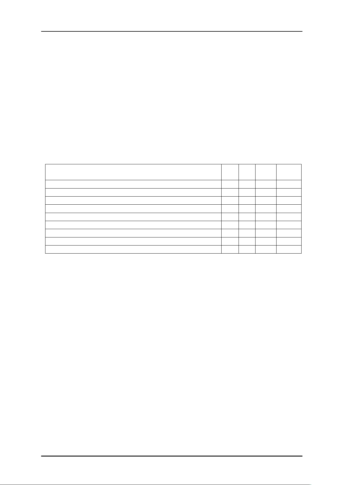
Most our products are transceivers, meaning they can transmit or receive W-DMX™ signals,
depending on how to set them up:
Product
TX
RX
Triple
Band
Double
Up
BlackBox F-1 G5
BlackBox F-2 G5
BlackBox R-512
WhiteBox F-1
WhiteBox F-2
Micro F-1
Micro R-512
ProBox F-2500
UglyBox G5
Page 8
User Manual - English
!
!
PAGE!
7!
3. The W-DMX™ Technology
!
W-DMX™ is solely engineered by Wireless Solution Sweden to provide the same quality, reliability
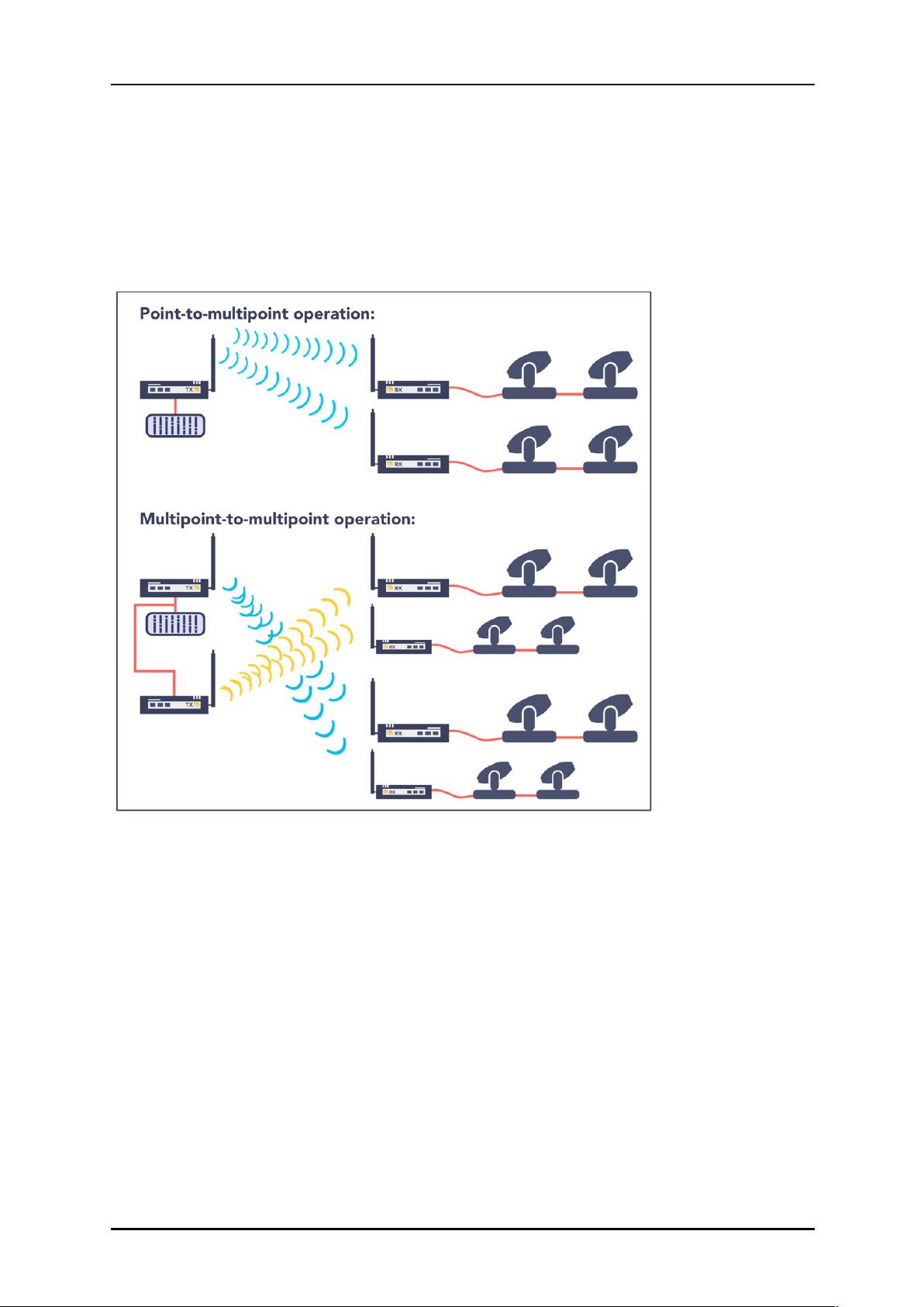
and performance as any wired DMX link. The technology allows you to establish point-to-point links,
point-to-multipoint and multipoint-to-multipoint:
W-DMX™ is unique in its use of advanced radio technologies that are also used in mobile phones
and military communication.
Rather than using fixed frequency channels, W-DMX™ uses Adaptive Frequency Hopping technology
to continually check the radio channels for interferences and to rapidly move operation to clear radio
channels. The checks are carried out in combination with another advanced technology: time division
multiple access. This technology makes the most efficient use of every visited frequency channel.
In order to guarantee a more reliable transmission, some W-DMX™ devices can operate on three
different frequency bands, allowing the user to move their transmission into an interference-free
spectrum. This is limited to some product ranges and countries.
Page 9
User Manual - English
!
!
PAGE!
8!
4. Operation
!
All W-DMX™ devices share the same user interface – these instructions apply to all products:
4.1. Basic setup – Linking devices
A basic setup is defined by the link between two devices. This means that, in order to send data
from a transmitter to a receiver, it’s necessary to pair the devices:
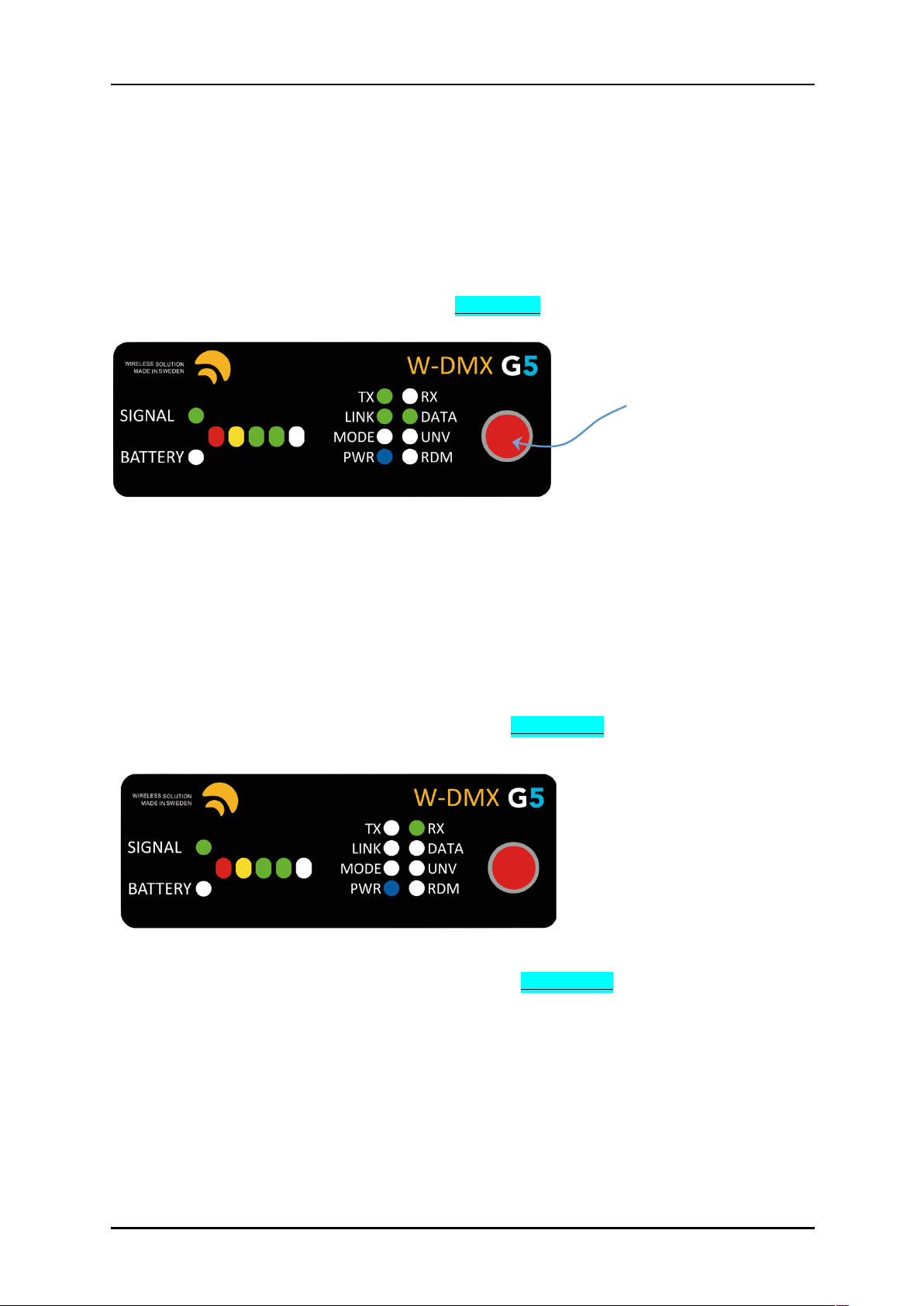
Press the red function button, on the transmitter, for 1 second, until the LINK LED starts flashing.
NOTE:
All available receivers, as long as they are turned on, will pair with this transmitter. The LINK
LED of each receiver will flash for 5 seconds, and stay static once linked up.
There is no limited amount of receivers that can link up with a transmitter – there can be an infinite
number of receivers all paired with a single transmitter.
4.2. Unlinking devices
There are two ways to unlink devices – individual unlink, or group unlink:
Individual unlink:
Press and hold the red function button, on each receiver, for 5 seconds. The LINK LED should turn
off.
!
Group unlink:
Press and hold the red function button, on the transmitter, for 5 seconds. All paired receivers will
unlink.
4.3. Linking multiple transmitters with multiple receivers
When multiple receivers need to be linked up with different transmitters, repeat the process in 3.1.,
but turn off all receivers you do not wish to pair up. For example:
- If you have 2 transmitters and 10 receivers, pair the first transmitter to 5 receivers, while the last
five are turned off.
- After that, turn the last five receivers, and pair them to the second transmitter.
NOTE:
This will not affect any receiver that has already been paired up.
red function button
Page 10
User Manual - English
!
!
PAGE!
9!
4.4. Switching FLEX mode
All units identified as a transceiver can be changed between transmitter or receiver – the units
capable to operate in both modes are listed in chapter 2.
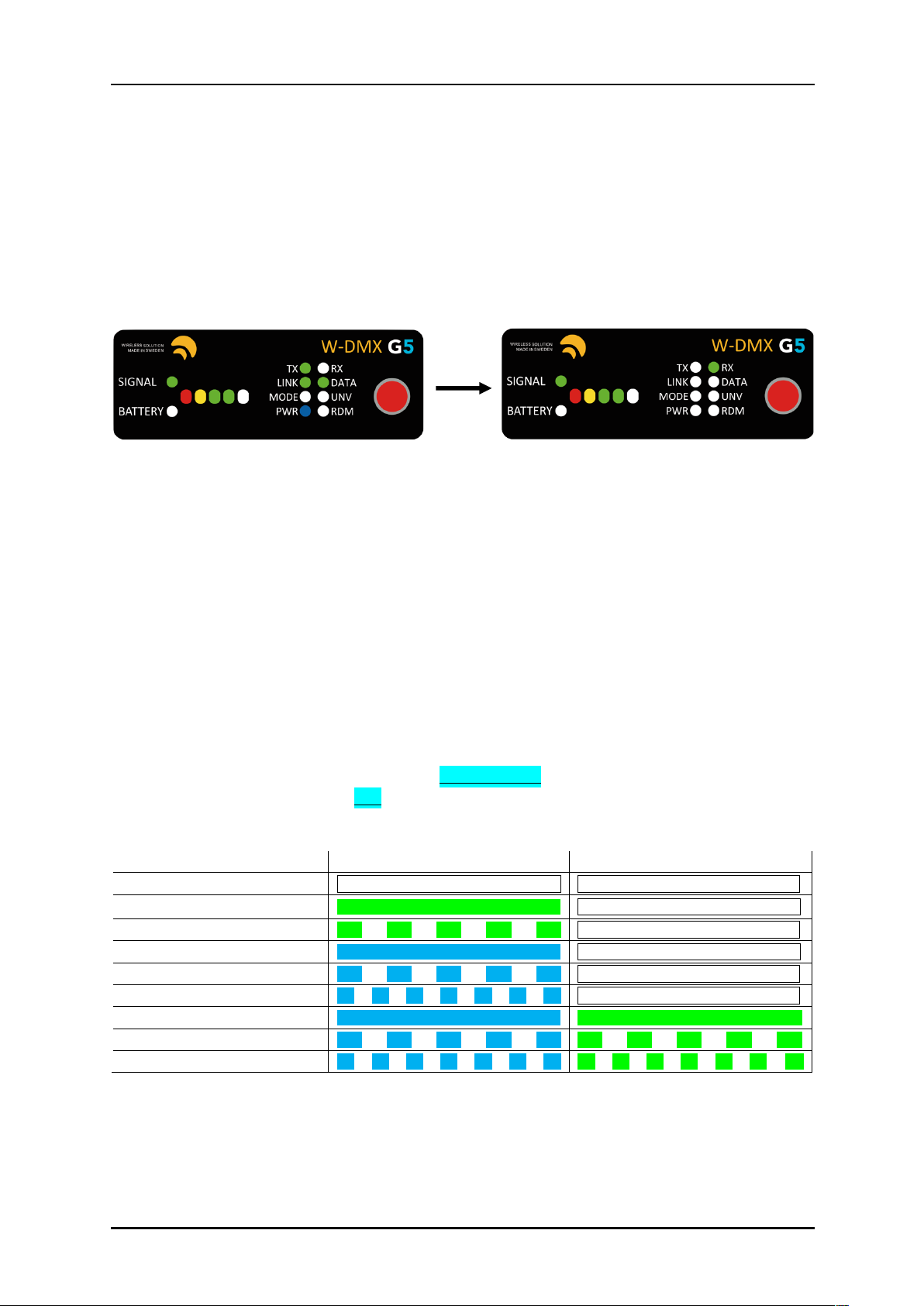
FLEX mode determines if the unit is used in transmit mode (TX) or receive mode (RX):
1. Disconnect the power cable
2. Press and hold the red function button on the front panel.
3. While holding the button, reconnect the power cable.
4. Release the red function button.
You will notice the TX LED will turn off, and the RX LED will turn on.
Repeat the same procedure to change from RX to TX.
4.4. Changing CTRL mode
!
There are several operating modes within all W-DMX™ products – these are like operating systems,
and allow you to be backward compatible with legacy products. They are:
G3 Mode [2.4 GHz]
G4 Mode [2.4 GHz & 5.8 GHz]
G5 Mode [2.4 GHz, 5.2 GHz & 5.8 GHz]
G5 Mode with double-up [2.4 GHz, 5.2 GHz & 5.8 GHz]
You can change between modes are any given moment – changes must be made to the transmitter:
1. Press and hold the red function button for 10 seconds
2. The top 4 LEDs will chase. Tap the red function button to scroll through all the modes.
3. There are 9 options available – you can understand the mode as follows:
MODE LED
UNV LED
G3
2.4 GHz
G4
2.4 GHz
G4
5.8 GHz
G5
2.4 GHz
G5
5.8 GHz
G5
5.2 GHz
G5
2.4 GHz Double-Up
G5
5.8 GHz Double-Up
G5
5.2 GHz Double-Up
4. Press and hold the red function button to save and exit.
NOTE!
All changes shall be made to the transmitter. It’s necessary to re-link all receivers after
changing control modes. Triple-band and double-up are not available in the Micro series.
Page 11
User Manual - English
!
!
PAGE!
10!
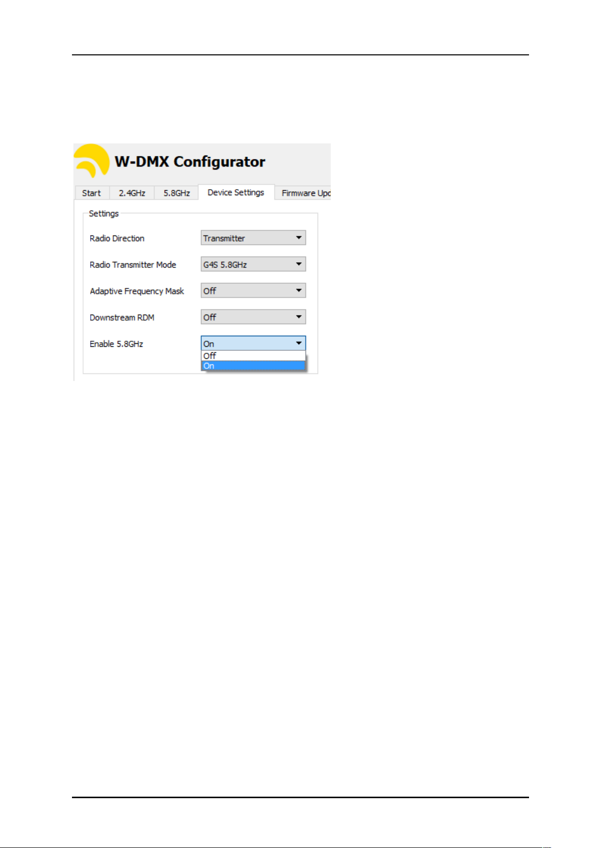
4.5. Enabling 5 GHz
Due to a few regulations worldwide, all W-DMX™ devices come with 5 GHz disabled from frontinterface control. This must be enabled with the W-DMX™ Dongle and Configurator software,
available from the website.
!
!
4.6. Double-Up Mode
In G5 series, all products except the Micro series come with Double-Up mode – this allows you to
send an extra universe wirelessly, just by changing the operating CTRL mode. By doing this, you
decrease the transmission range by 20%, but receive an extra 512 channels.
This is only available on the F-1 and F-2 models, not on R-512 models.
4.7. Repeater Mode
All F-2 models are capable to operate as repeaters, as long as configured to do so:
1. Set universes A and B into transmitter mode [see 4.4.]
2. With the W-DMX™ Dongle, set the master transmitter to “G4S repeater mode”
3. Set Universe B of the F-2 unit into “G4S repeater mode”
4. Set Universe A of the F-2 unit into “G4S receiver mode”
5. Link Universe A to the mater transmitter
6. Link the receivers to Universe B of the F-2 unit
Page 12
User Manual - English
!
!
PAGE!
11!
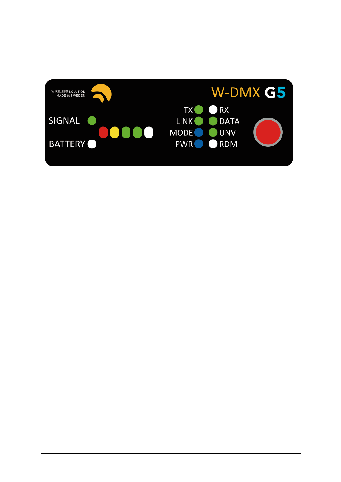
5. User Interface
Though the interface display appears simple, there is a lot of information you can read back, which
will help you troubleshooting and understanding how your device is operating.
1.
BATTERY
Only works on the Micro series. Indicates battery-life of the device.
2. SIGNAL
Will stay always on, except on the Micro, where it warns about battery-life
3. SIGNAL STATUS
On a transmitter, indicates the power output in mW. Full bar indicates
500mW, two green LEDs indicates 375mW (EU max.), one green LED indicates 100mW (DE
max.), yellow LED indicates 25mW.
On a receiver, indicates signal strength.
4. TX
Device operating as a transmitter.
5. RX
Device operating as a receiver.
6. LINK
On a transmitter, it states it’s ready to establish a link. On a receiver, if off, indicates it’s
got no active link, if on, it indicates it’s already paired to a transmitter. If blinking
intermittently, it indicates that it has lost its link [either the transmitter is out-of-range or
turned off].
7. DATA
It indicates whether data is being sent to the transmitter/receiver. If the LED is off,
check if the DMX cable is plugged correctly to the transmitter.
8. MODE
Indicates the CTRL mode [See chapter 3.4].
9. UNV
Indicates double-up mode.
10. PWR
States power condition of the device.
11. RDM
Indicates whether RDM is active or disabled.
12. Red function button.
1
2
3
4 5 6
8
10
7
9
11
12
Page 13

User Manual - English
!
!
PAGE!
12!
1 2 3 4 5 6 7 2 1 4 3
6. Hardware
6.1. BlackBox Series
!
!
!
!
!
!
!
!
!
1.
AC Power Input
Uac = 90-250V / 50-440 Hz
PowerCon® 20A connector
2.
EtherCon RJ45 port
NOTE
Ethernet based-protocols are only available if the Ethernet extension is mounted. This is an
optional feature available for purchase.
3. XRL female 5 pin [Universe 1]
4. XRL male 5 pin [Universe 1]
5. XRL female 3 pin [Universe 2 in Double-Up mode]
6. XRL female 3 pin [Universe 2 in Double-Up mode]
7. 12V DC power supply [- / +]
NOTE
The R-512 model does not receive in double-up mode, only the first universe will be received.
6.1.1 BlackBox F-2 Double-Up explained
!
G3/G4/G5 Mode:
1. Universe A In
2. Universe A Out
3. Universe B In
4. Universe B Out
Double-Up Mode:
1. Universe 1 In/Out
2. Universe 2 In/Out
3. Universe 3 In/Out
4. Universe 4 In/Out!!
6.1.2 Contents included
When you purchase a new BlackBox, the following items are included:
• BlackBox device (R-512, F-1 or F-2)
• User Manual
• Antenna Adapter [90 Deg]
• 3dBi Antenna
• Mounting brackets
• Phoenix DC connector
NOTE
Power cable is not included.
Page 14
User Manual - English
!
!
PAGE!
13!
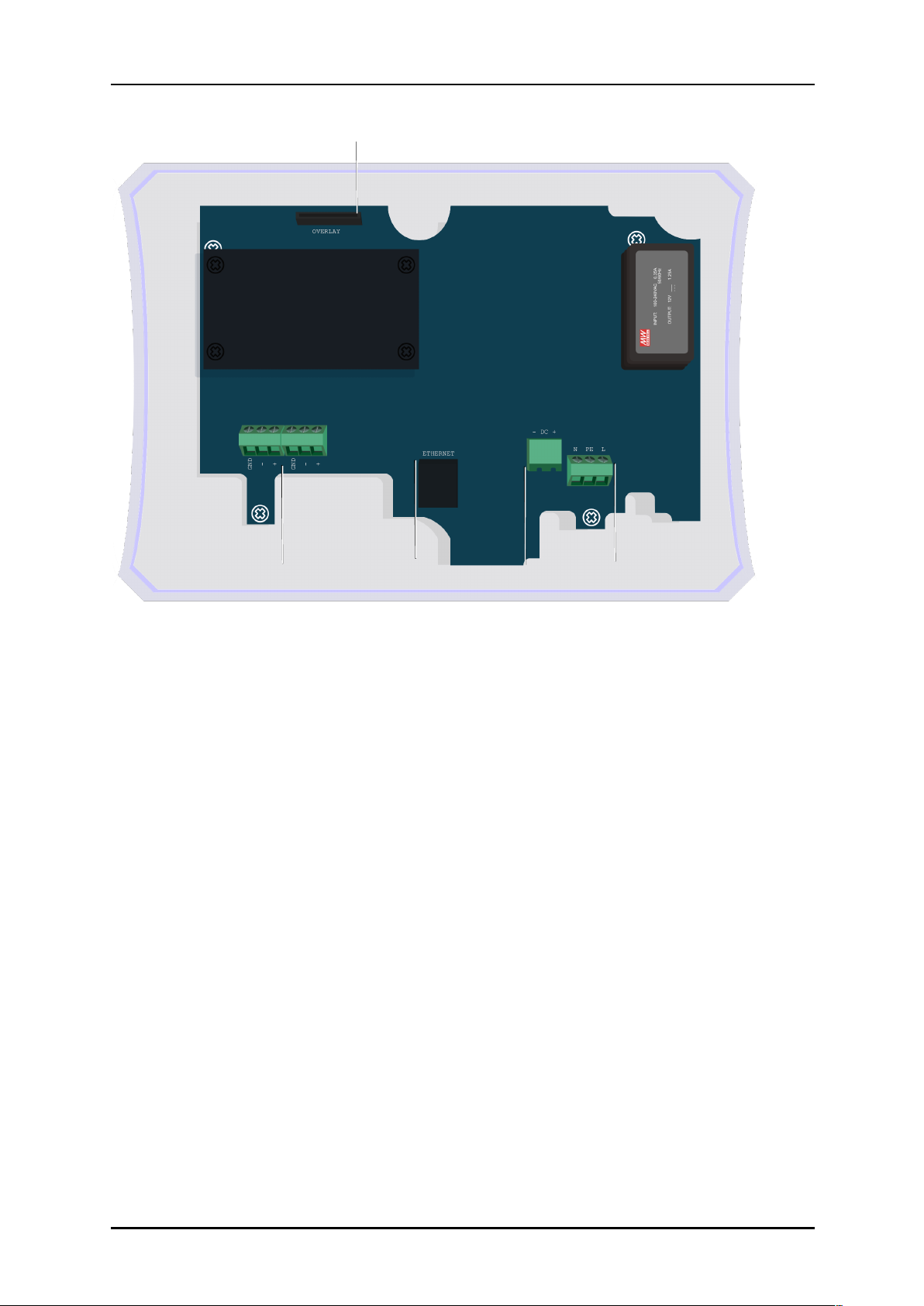
6.2. WhiteBox Series
1. Overlay connector
2. DMX input and/or output
3. Ethernet RJ45 port
4. 12V DC power supply [- / +]
5. AC power input
Uac = 90-250V / 50-440 Hz
N / EARTH / L
6.2.1 WhiteBox Double-Up explained
G3/G4/G5 Mode:
XLR 1. Universe A In
XLR 2. Universe A Out
XLR 3. Universe B In
XLR 4. Universe B Out
Double-Up Mode:
XLR 1. Universe 1 In/Out
XLR 2. Universe 2 In/Out
XLR 3. Universe 3 In/Out
XLR 4. Universe 4 In/Out!!
6.2.2 Contents included
When you purchase a new ProBox, the following items are included:
• WhiteBox device (F-1 or F-2)
• User Manual
• 3dBi Antennae
NOTE
Power or DMX cables are not terminated or included with this device.
2 4 5
3
1
XLR1
XLR2
Page 15

User Manual - English
!
!
PAGE!
14!
6.3. Micro Series
!
!
!
!
!
!
!
!
!
!
!
!
!
!
1. Kensington security slot
2. XLR female 5 pin (Female on R-512 models, male for F-1 models)
3. Power switch
4. Micro USB 5V power connector
!
NOTE
Micro series do not operate in double-up mode or in triple-band.
6.3.1 Contents included
When you purchase a new Micro unit, the following items are included:
• Micro device (R-512 or F-1)
• User Manual
• USB adaptor with universal plugs
• Velcro strap
1
2
3
4
Page 16
User Manual - English
!
!
PAGE!
15!
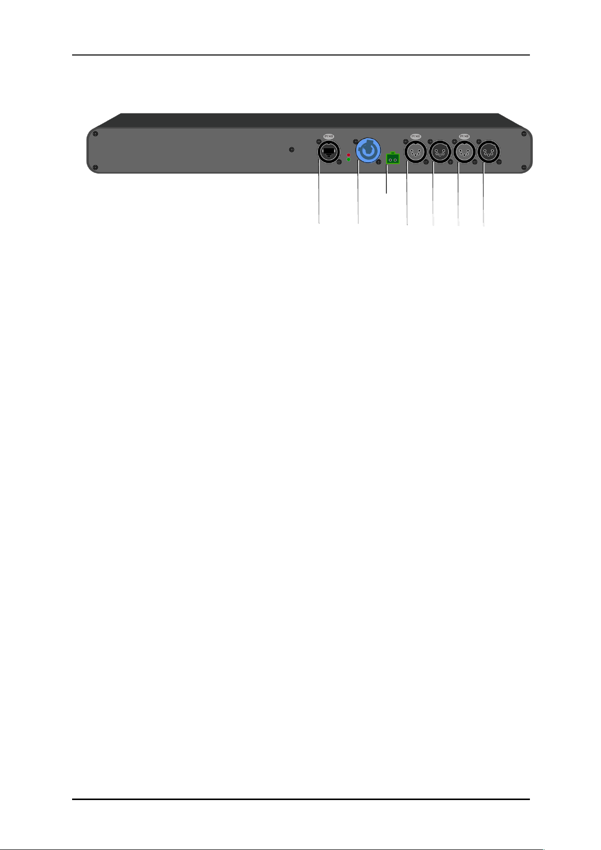
6.4. ProBox Series
1. XRL male 5 pin [Universe A]
2. XRL female 5 pin [Universe A]
3. XRL male 5 pin [Universe B]
4. XRL female 5 pin [Universe B]
5. 12V DC power supply [- / +]
6.
AC Power Input
Uac = 90-250V / 50-440 Hz
PowerCon® 20A connector
7. EtherCon RJ45 port
6.4.1 BlackBox F-2 Double-Up explained
G3/G4/G5 Mode:
1. Universe A In
2. Universe A Out
3. Universe B In
4. Universe B Out
Double-Up Mode:
1. Universe 1 In/Out
2. Universe 2 In/Out
3. Universe 3 In/Out
4. Universe 4 In/Out!!
6.4.2 Contents included
When you purchase a new ProBox, the following items are included:
• ProBox F-2500 device
• User Manual
• 2x Antenna Adapter [90 Deg]
• 2x 3dBi Antenna
• Phoenix DC connector
NOTE
Power cable is not included.
7 6 5
4
3
2
1
Page 17
User Manual - English
!
!
PAGE!
16!
7. Upgrades and Updates
7.1. Ethernet Upgrade
Coming soon.
7.2. Wi-Fi Upgrade
Coming soon.
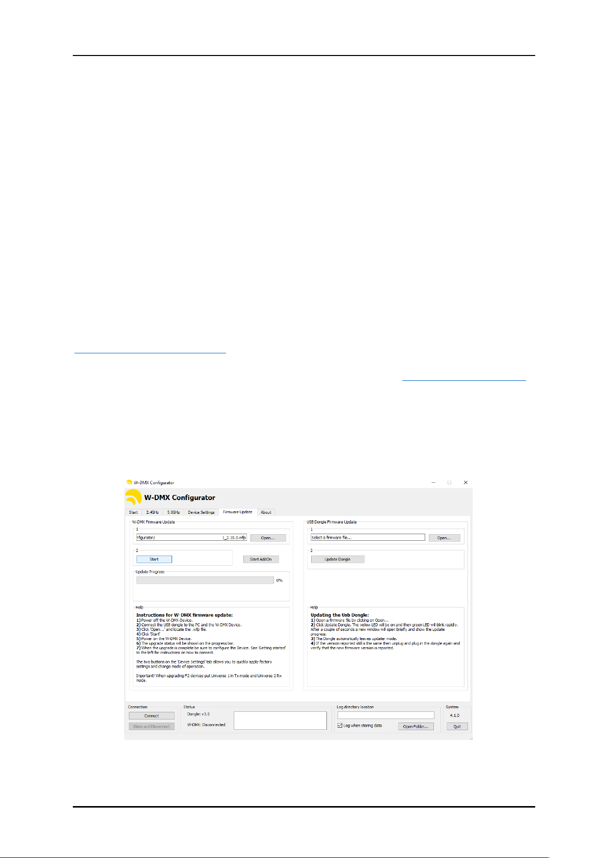
7.3. Firmware Update
Wireless Solution is committed to developing and improving its wireless technology – though
firmware updates are not constant, occasionally there is a need to release a new version, whether
related to the transmission itself, glitches with the interface or RDM implementation.
All products are updatable, including OEM devices. For that, it’s necessary to obtain a W-DMX™
Dongle – this is a USB to DMX interface that connects straight to any device. We encourage to get
one per W-DMX™ kit.
The software interface can be found on Wireless Solution’s website:
www.wirelessdmx.com/download
New firmware versions can be found on Wireless Solution’s RMA portal: www.wirelessdmx.com/rma
Instructions:
1. Connect the dongle to your computer, and the DMX cable to the W-DMX™ device.
2. Before powering-up the device, load the new firmware version.
3. Press start and turn on the device.
!
NOTE
Follow carefully all the instructions in the ‘Help’ section, within the software.
Page 18
User Manual - English
!
!
PAGE!
17!
7. Recommendations
There are several tips and tricks that could make your wireless transmission work better. Here’s a few
that should be followed:
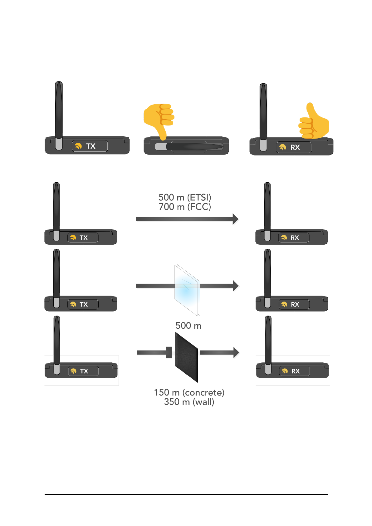
Fig.1:
It’s important that all antennas point to the same axis – wireless waves have a radial pattern
that should be valued. There are a number of accessories that can help maintaining directionality.
Fig.2:
There are limitations to how wireless waves propagate through air. Physical barriers like glass,
concrete and walls will limit the transmission range. Always try to have clear line-of-sight between
transmitters and receivers.
Page 19
User Manual - English
!
!
PAGE!
18!
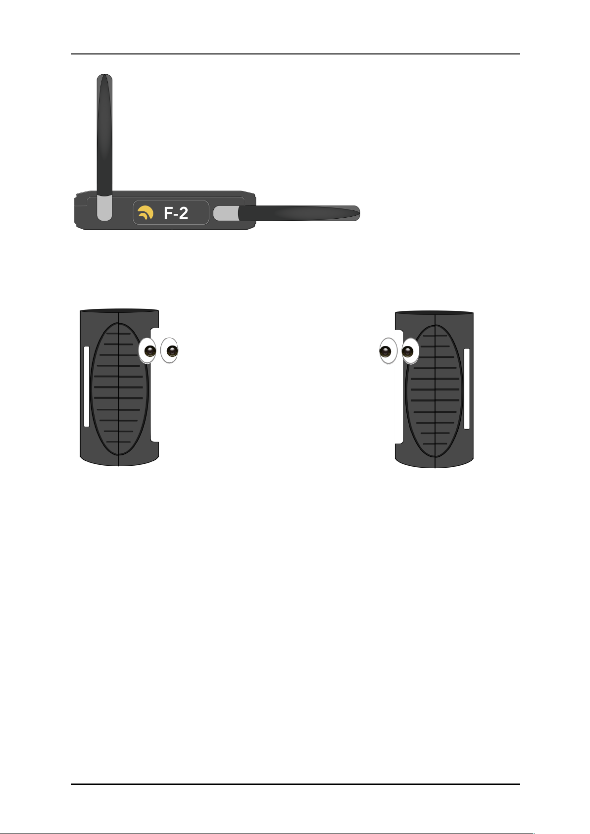
Fig.3:
It’s possible to increase performance of dual-universe devices just by rotating one of the
antennas to a different axis. This will avoid the radio-waves of both transmissions to interference with
each other.
Fig.4:
Micros like to be seen – just because it’s small, don’t throw it inside a box! They have a very
sensitive antenna that doesn’t like barriers. And most of all, always point their display to each other –
that’s where their optimum performance is!
Page 20

 Loading...