

Page 1

MS4000
Gigabit Ethernet Switch
MS4000 Installation Guide
Page 2

Page 3

MS4000 Installation Guide
Page 4

MS4000 Installation Guide
WS-DOC-MS4K-INSTALL. Published February 14, 2019.
Copyright and Legal notice
Copyright 2012-2019 Waystream AB. All rights reserved.
iBOS, the ASR Bootloader, program models and other software content and this documentation
(“the Intellectual Property Rights”) are protected by the Swedish Copyright Act (Sw: Upphovsrättslagen) and, if applicable, the Swedish Patents Act (Sw: Patentlagen). All and any copying and distribution of the Intellectual Property Rights, without authorization by Waystream is prohibited. The
prohibition includes every form of reproduction and distribution.
Every effort was made to ensure that the information in this document was complete and accurate
at the time of printing. However, information is subject to change without notice. Waystream assumes no liability for damages incurred directly or indirectly from errors, omissions or discrepancies
between the software and this document.
iBOS, ServiceEngine, MS4000-series switches and ASR are trademarks of Waystream.
All other trademarks, service marks and trade names are proprietary to their respective owner.
Purchasers, licensees and users accept and acknowledge that the products contain components
(including components carrying certain firmware) and combinations of components that constitute
trade secrets protected by Waystream or its partners. Purchasers, licensees and users warrant that
the delivered products will not be opened or dismantled, copied, altered or in any other way modified. Furthermore, purchasers, licensees and users agree not to attempt to reverse engineer, disassemble, modify, translate, create derivate works, rent, lease, loan, or without written permission
distribute or sublicense the software, in whole or in part.
The products and its hardware, firmware and software, including technical data, may be subject to
EU and U.S export control laws, including the U.S Export Administration Act and its associated
regulations and the International Traffic in Arms Regulations administered by the US Department
of State, and may be subject to export or import regulations in other countries. Purchasers and
licensees agree to comply strictly with all such regulations and acknowledges that it has the responsibility to obtain licenses to export, re-export, or import hardware, firmware and software.
Purchasers and licensees are not entitled to, and Waystream is not in any event liable to pay,
compensation for damages which delivered products or software has caused to other property or
to persons or any other consequential damages, including but not limited to loss of profit, loss of
production or any other indirect damages.
Page 5

Contents
Introduction . . . . . . . . . . . . . . . . . . . . . . . . . . . . . . . . . . . . . . . . . . . . . . . . . . . . . . . . . 3
Product Overview . . . . . . . . . . . . . . . . . . . . . . . . . . . . . . . . . . . . . . . . . . . . . . . . . . . . . 5
Product Models . . . . . . . . . . . . . . . . . . . . . . . . . . . . . . . . . . . . . . . . . . . . . . . . . . . . . . . . . . . . . . . 6
MS4026. . . . . . . . . . . . . . . . . . . . . . . . . . . . . . . . . . . . . . . . . . . . . . . . . . . . . . . . . . . . . . . . . . 6
MS4126. . . . . . . . . . . . . . . . . . . . . . . . . . . . . . . . . . . . . . . . . . . . . . . . . . . . . . . . . . . . . . . . . . 7
MS4226. . . . . . . . . . . . . . . . . . . . . . . . . . . . . . . . . . . . . . . . . . . . . . . . . . . . . . . . . . . . . . . . . . 7
MS4326. . . . . . . . . . . . . . . . . . . . . . . . . . . . . . . . . . . . . . . . . . . . . . . . . . . . . . . . . . . . . . . . . . 8
The MS4000 Front Panel . . . . . . . . . . . . . . . . . . . . . . . . . . . . . . . . . . . . . . . . . . . . . . . . . . . . . . . . 9
LED Panel . . . . . . . . . . . . . . . . . . . . . . . . . . . . . . . . . . . . . . . . . . . . . . . . . . . . . . . . . . . . . . . . 9
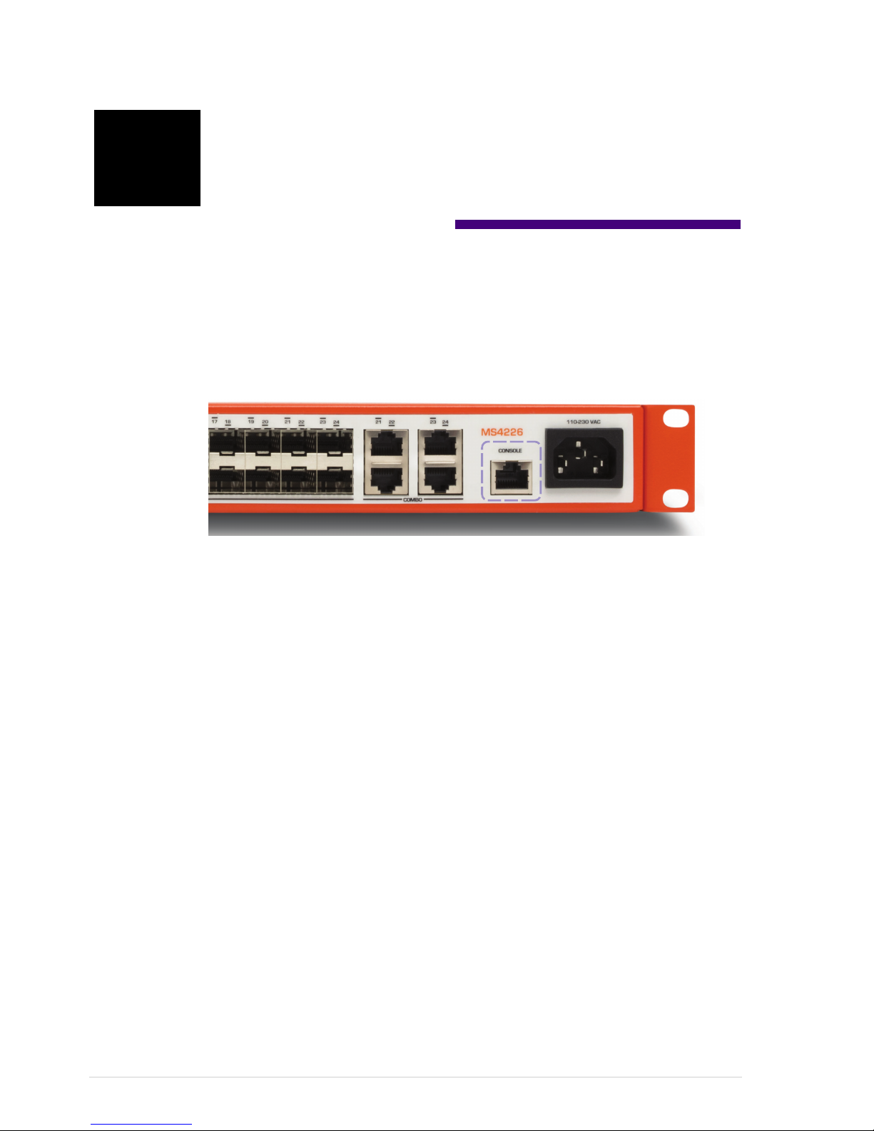
Console Port . . . . . . . . . . . . . . . . . . . . . . . . . . . . . . . . . . . . . . . . . . . . . . . . . . . . . . . . . . . . . 13
MS4000 Power Connector . . . . . . . . . . . . . . . . . . . . . . . . . . . . . . . . . . . . . . . . . . . . . . . . . . . 13
MS4000 Ground Connectors . . . . . . . . . . . . . . . . . . . . . . . . . . . . . . . . . . . . . . . . . . . . . . . . . . . . 14
Installing the MS4000 . . . . . . . . . . . . . . . . . . . . . . . . . . . . . . . . . . . . . . . . . . . . . . . . 15
Tools Required. . . . . . . . . . . . . . . . . . . . . . . . . . . . . . . . . . . . . . . . . . . . . . . . . . . . . . . . . . . . . . . 15
Safety Guidelines. . . . . . . . . . . . . . . . . . . . . . . . . . . . . . . . . . . . . . . . . . . . . . . . . . . . . . . . . . . . . 15
General Safety . . . . . . . . . . . . . . . . . . . . . . . . . . . . . . . . . . . . . . . . . . . . . . . . . . . . . . . . . . . . 15
Operating Safety . . . . . . . . . . . . . . . . . . . . . . . . . . . . . . . . . . . . . . . . . . . . . . . . . . . . . . . . . . 16
EMC Notice . . . . . . . . . . . . . . . . . . . . . . . . . . . . . . . . . . . . . . . . . . . . . . . . . . . . . . . . . . . . . . 16
Equipment List. . . . . . . . . . . . . . . . . . . . . . . . . . . . . . . . . . . . . . . . . . . . . . . . . . . . . . . . . . . . . . . 17
MS4000 Environment . . . . . . . . . . . . . . . . . . . . . . . . . . . . . . . . . . . . . . . . . . . . . . . . . . . . . . . . . 18
Ventilation of MS4000 . . . . . . . . . . . . . . . . . . . . . . . . . . . . . . . . . . . . . . . . . . . . . . . . . . . . . . 19
Rack Installation of MS4000 . . . . . . . . . . . . . . . . . . . . . . . . . . . . . . . . . . . . . . . . . . . . . . . . . 19
Connecting Power to the MS4000 . . . . . . . . . . . . . . . . . . . . . . . . . . . . . . . . . . . . . . . . . . . . . 20
Installing SFP Modules. . . . . . . . . . . . . . . . . . . . . . . . . . . . . . . . . . . . . . . . . . . . . . . . . . . . . . 21
Connecting the MS4000 to the Network. . . . . . . . . . . . . . . . . . . . . . . . . . . . . . . . . . . . . . . . . 21
Checking the Switch Installation. . . . . . . . . . . . . . . . . . . . . . . . . . . . . . . . . . . . . . . . 23
Connecting to the Console Interface Port . . . . . . . . . . . . . . . . . . . . . . . . . . . . . . . . . . . . . . . . . . . 23
The Boot Process. . . . . . . . . . . . . . . . . . . . . . . . . . . . . . . . . . . . . . . . . . . . . . . . . . . . . . . . . . . . . 24
Troubleshooting the Bootloader . . . . . . . . . . . . . . . . . . . . . . . . . . . . . . . . . . . . . . . . . . . . . . . . . . 24
No Uplink during Boot . . . . . . . . . . . . . . . . . . . . . . . . . . . . . . . . . . . . . . . . . . . . . . . . . . . . . . 24
No valid iBOS Image during Boot . . . . . . . . . . . . . . . . . . . . . . . . . . . . . . . . . . . . . . . . . . . . . . 25
Troubleshooting iBOS . . . . . . . . . . . . . . . . . . . . . . . . . . . . . . . . . . . . . . . . . . . . . . . . . . . . . . . . . 26
Check System . . . . . . . . . . . . . . . . . . . . . . . . . . . . . . . . . . . . . . . . . . . . . . . . . . . . . . . . . . . . 26
Check Available PFDP Devices . . . . . . . . . . . . . . . . . . . . . . . . . . . . . . . . . . . . . . . . . . . . . . . . 27
Check SFP Interfaces. . . . . . . . . . . . . . . . . . . . . . . . . . . . . . . . . . . . . . . . . . . . . . . . . . . . . . . 27
Check the Uplink Interface . . . . . . . . . . . . . . . . . . . . . . . . . . . . . . . . . . . . . . . . . . . . . . . . . . . 28
Check VLAN Interfaces. . . . . . . . . . . . . . . . . . . . . . . . . . . . . . . . . . . . . . . . . . . . . . . . . . . . . . 29
Page 6

Appendix A – MS4000 Product Description . . . . . . . . . . . . . . . . . . . . . . . . . . . . . . . 31
MS4000 Interfaces . . . . . . . . . . . . . . . . . . . . . . . . . . . . . . . . . . . . . . . . . . . . . . . . . . . . . . . . . . . 31
Interface Specification . . . . . . . . . . . . . . . . . . . . . . . . . . . . . . . . . . . . . . . . . . . . . . . . . . . . . . 31
Technical Data. . . . . . . . . . . . . . . . . . . . . . . . . . . . . . . . . . . . . . . . . . . . . . . . . . . . . . . . . . . . . . . 32
Physical Dimensions . . . . . . . . . . . . . . . . . . . . . . . . . . . . . . . . . . . . . . . . . . . . . . . . . . . . . . . 32
Power and Safety. . . . . . . . . . . . . . . . . . . . . . . . . . . . . . . . . . . . . . . . . . . . . . . . . . . . . . . . . . 32
Environmental . . . . . . . . . . . . . . . . . . . . . . . . . . . . . . . . . . . . . . . . . . . . . . . . . . . . . . . . . . . . 32
Appendix B – SFP Products . . . . . . . . . . . . . . . . . . . . . . . . . . . . . . . . . . . . . . . . . . . 33
Overview . . . . . . . . . . . . . . . . . . . . . . . . . . . . . . . . . . . . . . . . . . . . . . . . . . . . . . . . . . . . . . . . . . . 33
Safety . . . . . . . . . . . . . . . . . . . . . . . . . . . . . . . . . . . . . . . . . . . . . . . . . . . . . . . . . . . . . . . . . . . . . 35
Insertion and Removal . . . . . . . . . . . . . . . . . . . . . . . . . . . . . . . . . . . . . . . . . . . . . . . . . . . . . . . . . 37
Inserting an SFP module . . . . . . . . . . . . . . . . . . . . . . . . . . . . . . . . . . . . . . . . . . . . . . . . . . . . 37
Removing an SFP Module . . . . . . . . . . . . . . . . . . . . . . . . . . . . . . . . . . . . . . . . . . . . . . . . . . . . . . 37
Page 7

3
Introduction
The MetroStar 4000 (MS4000) is a versatile accesslayer switch for broadband
networks. The switch is available in two models with different interface types that make
it possible to use the MS4000 for all types of network access solutions.
This manual is intended for persons installing MS4000 units in a network. You will
need to be familiar with the Waystream products including iBOS, and the hardware
used in your networking system.
After reading this manual, you will be able to install, power up and handle basic
troubleshooting of the MS4000 series switch.
This manual describes the following:
• “Product Overview” on page 5
• “Installing the MS4000” on page 15
• “Checking the Switch Installation” on page 23
• “MS4000 Product Description” on page 31
• “SFP Products” on page 33
For complete information of the product, including specifications for hardware and
software functionality, refer “MS4000 Product Specification”.
For more information on configuring the boot options of the MS4000, refer “MS4000
Bootloader User Guide”.
Page 8

MS4000 Installation Guide
4
Page 9
5
Product Overview
This chapter provides an overview of the MS4000 for installation purposes only.
For a complete specification of the product, refer “MS4000 Product Description” on
page 31.
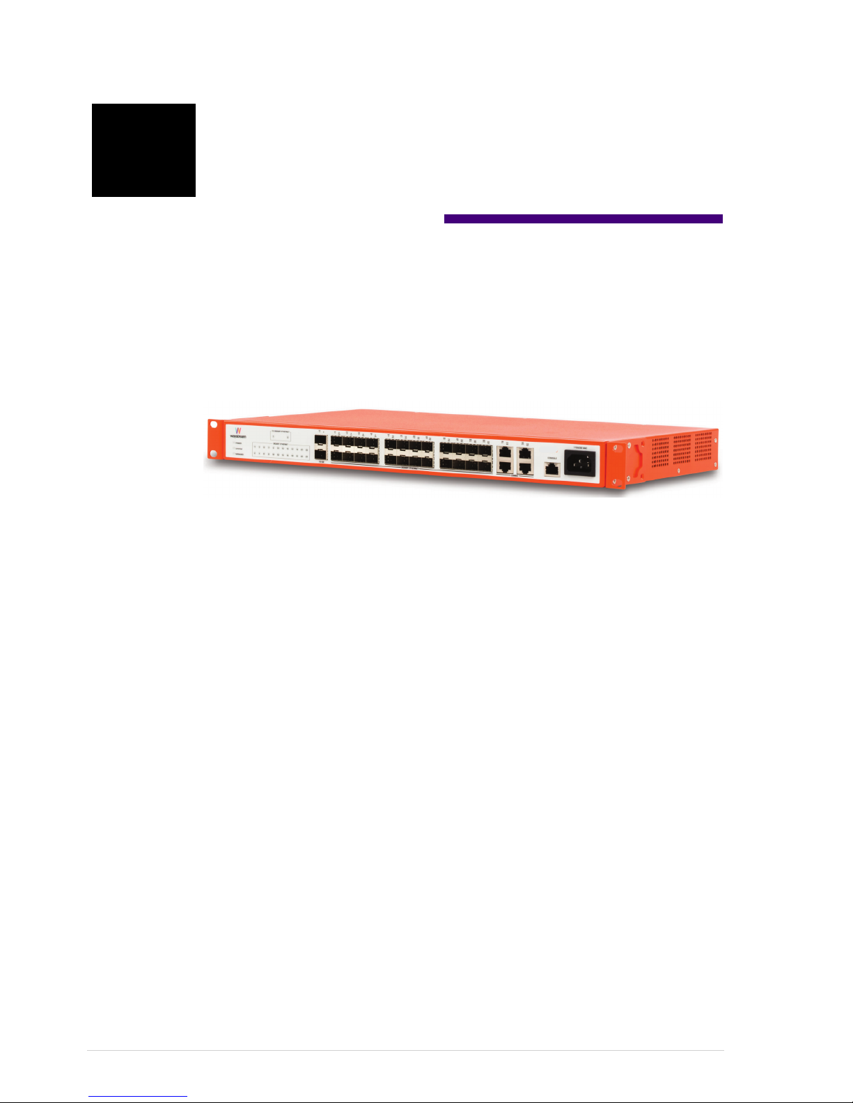
Figure 1 MS4000 Series Switch
The MS4000 is designed for installation in a standard 19” rack.
Page 10
MS4000 Installation Guide
6
Product Models
The MS4000 series switches are fancooled, and are designed for central office
environments.
This installation guide covers the following models of the MS4000 series router.
• MS4026
• MS4126
• MS4226
• MS4326
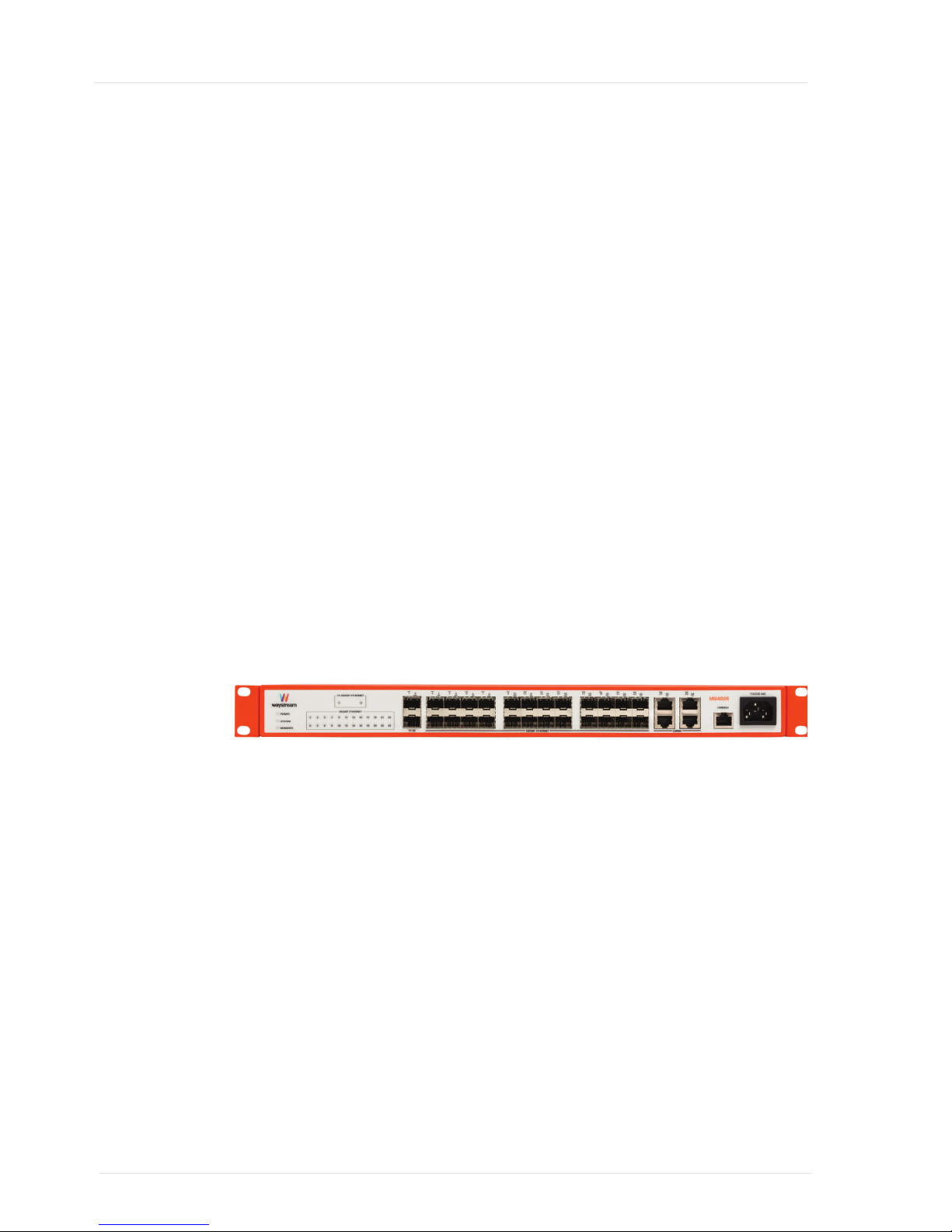
MS4026
The MS4026 has the following interfaces:
• Two (2) 10 GigabitEthernet SFP+ uplink slots
• One (1) RJ45 serial console port
• Twenty Four (24) GigabitEhernet SFP downlink slots
• Twenty (20) GigabitEthernet SFP downlink slots along with Four (4) RJ45 ports
The MS4026 is available as an AC model.
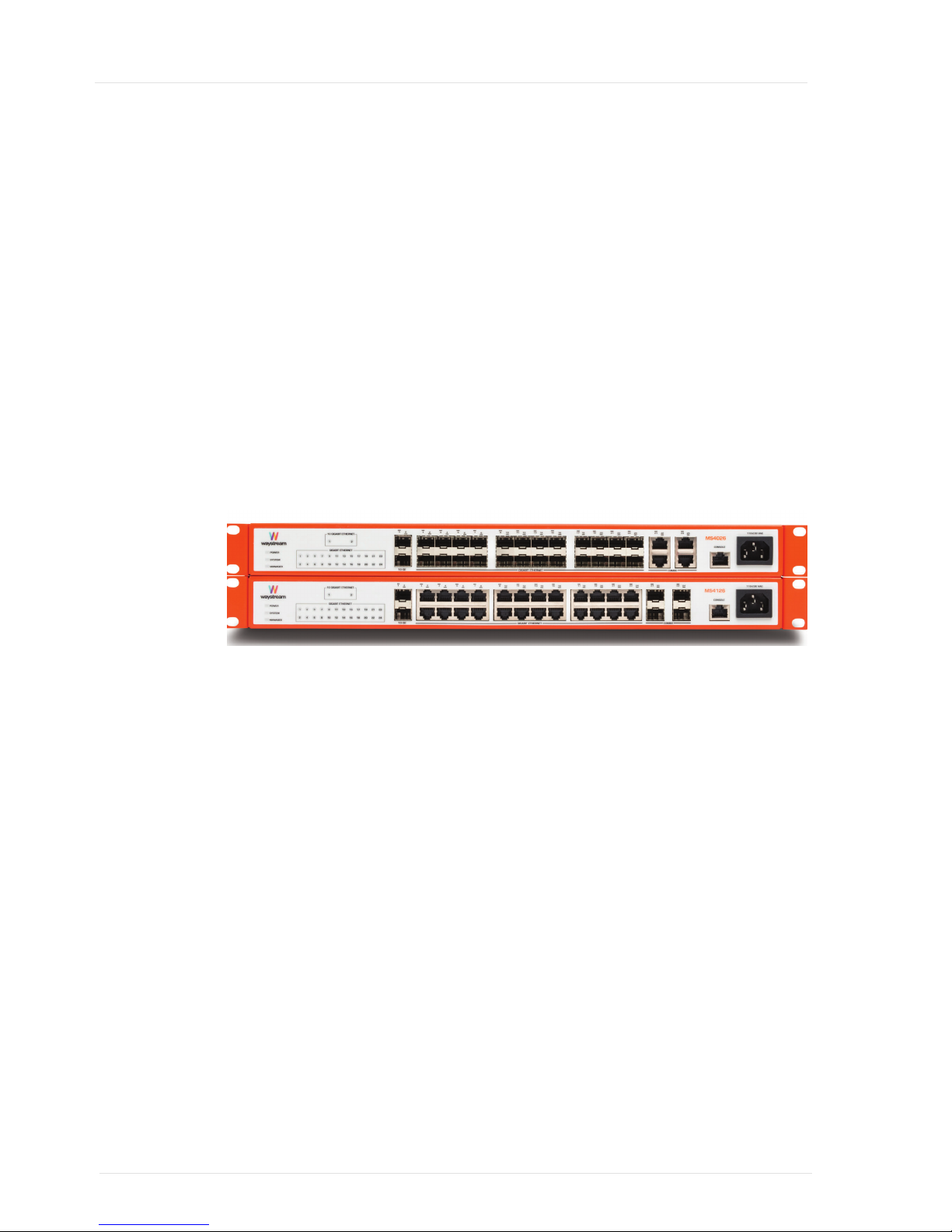
Figure 2 MS4026
The 24 GigabitEthernet interfaces are capable of running 100/1000 Mbps on fibre
cables. In addition, there are four RJ45 interfaces that can be used with twisted pair
(TP) Category 36 UTP/STP cables.
Page 11
Product Overview
7
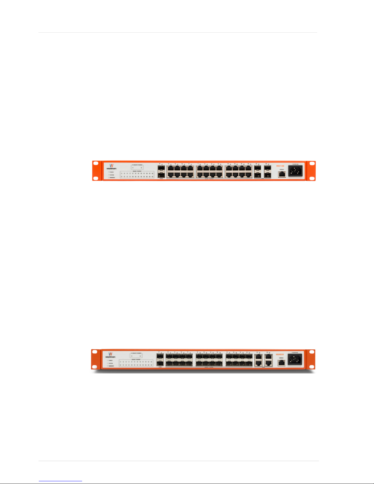
MS4126
The MS4126 series has the following interfaces:
• Two (2) 10 GigabitEthernet SFP+ uplink ports
• One (1) RJ45 serial console port
• Twenty Four (24) GigabitEhernet RJ45 downlink ports
• Four (4) SFP combo ports
The MS4026 is only available as an AC model.
Figure 3 MS4126
The 24 GigabitEthernet interfaces are RJ45 ports that are capable of running 10/100/
1000 Mbps on twisted pair (TP) Category 36 UTP/STP cables. In addition, there are
four SFP combo ports that can be used with fiber connectors at 100/1000 Mbps.
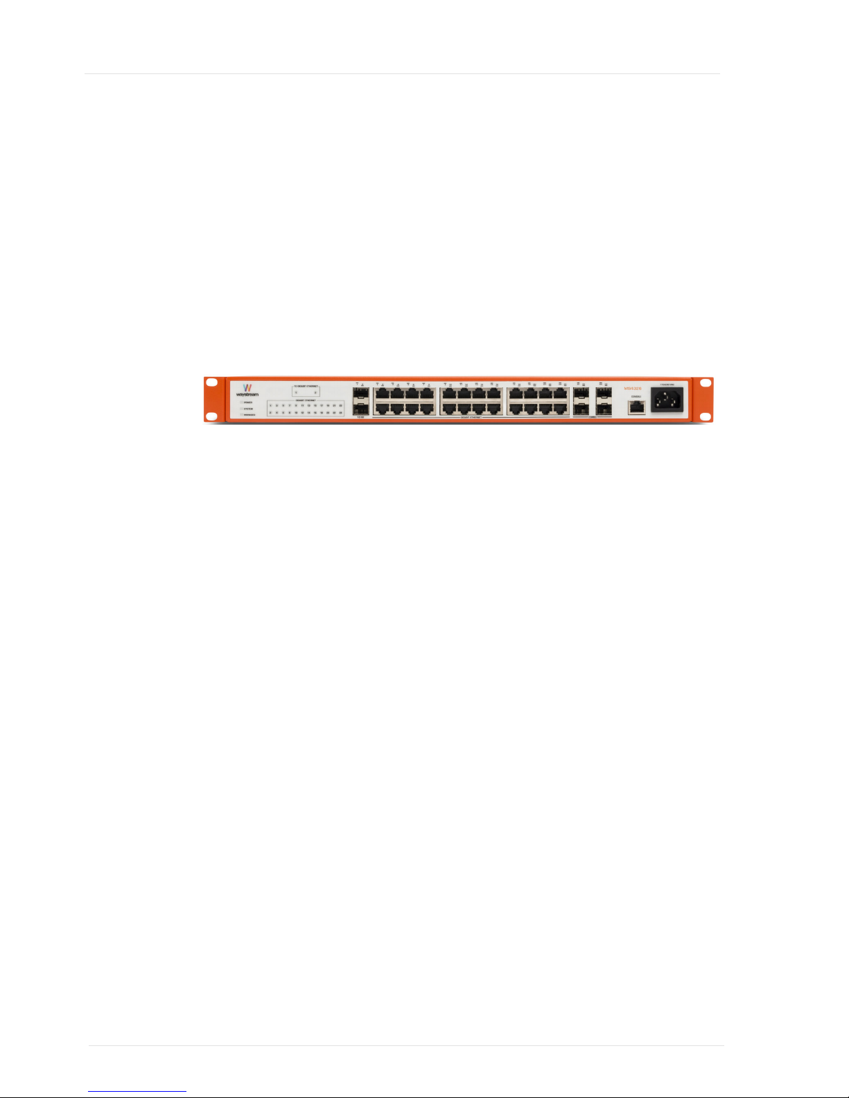
MS4226
The MS4226 series has the following interfaces:
• Two (2) 10 GigabitEthernet SFP+ uplink ports
• One (1)RJ45 serial console port
• Twenty Four (24) GigabitEhernet RJ45 downlink ports
• Four (4) RJ45 combo ports
The MS4226 is only available as an AC model.
Figure 4 MS4226
Page 12
MS4000 Installation Guide
8
MS4326
The MS4326 series has the following interfaces:
• Two (2) 10 GigabitEthernet SFP+ uplink ports
• One (1) RJ45 serial console port
• Twenty Four (24) GigabitEhernet RJ45 downlink ports
• Four (4) SFP combo ports
The MS4326 is only available as an AC model.
Figure 5 MS4326
Page 13
Product Overview
9
The MS4000 Front Panel
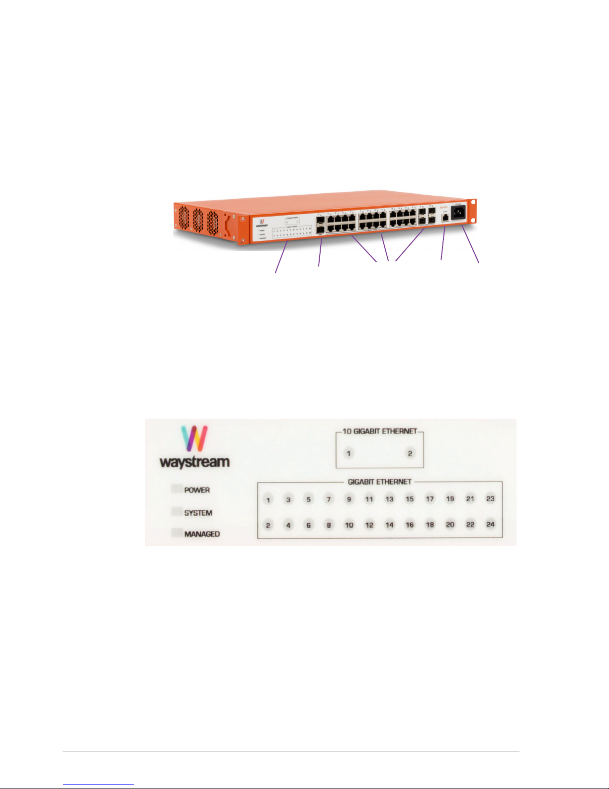
All connectors are placed in the front of the switch for easy operation. There is also an
LED panel that shows the status for all interfaces and the power supply.
Figure 6 MS4000 Front Panel
LED Panel
The LED panel displays the status of power supply, system, remote management, as
well as uplink and downlink interfaces.
Figure 7 MS4000 LED Panel
Uplink
Interfaces
Downlink
Interfaces
LED Panel
Console
Interface
Power
Connector
Page 14

MS4000 Installation Guide
10
System LEDs
The MS4000 has three LEDs for showing system status; POWER, SYSTEM and
MANAGED. Refer for more information.
Figure 8 System status Indicators
Table 1 System Status LED Status
LED STATE Description
POWER OFF
ON
FLASHING
Power is OFF
Power is ON.
switch is overheating.
SYSTEM OFF
ON
FLASHING
System is not loaded
System successfully booted.
System is booting
MANAGED OFF
ON
FLASHING
iBOS has started
Connected to remote management system
Manual configuration
Page 15
Product Overview
11
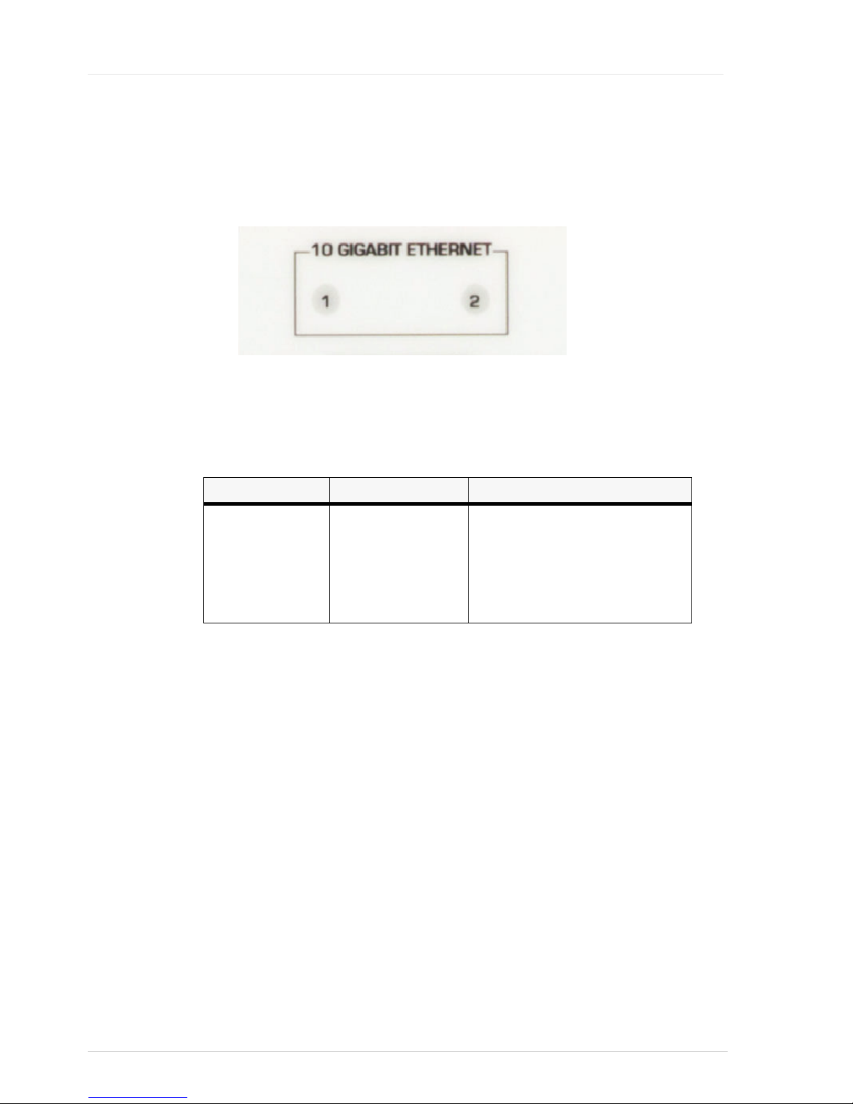
LED for Uplink Interfaces
For the uplink interfaces, the unit has two slots for SFP+ modules that can reach speeds
of upto 10 Gbps. Read more about the SFPs in “SFP Products” on page 33.
Figure 9 Uplink LEDs
When an uplink interface is active, the status is shown on the LED panel. Refer q~ÄäÉ
O.
Table 2
Uplink LED Status
10 GE LED STATE Description
12 OFF
ON
FLASHING
No uplink established
Uplink is established
GREEN=10 Gbps
AMBER= 1 Gbps
Uplink port is active, packets sent on port
GREEN= 10 Gbps
AMBER=1 Gbps
Page 16
MS4000 Installation Guide
12
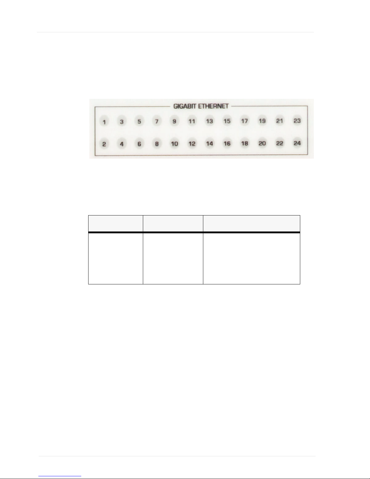
LED for Downlink Interfaces
For the downlink interfaces, the unit has 24 LEDs. The number corresponds to the
downlink port.
Figure 10 Downlink LEDs
Depending on the model and usage of the combo ports, these interfaces can operate at
10, 100 or 1000 Mbps. Refer q~ÄäÉ=P for description of the different states:
Table 3 Downlink LED Status
GIGABITETHERNET
LED
STATE Description
124 OFF
ON
FLASHING
No downlink established.
Downlink is established
GREEN= 1 Gbps
AMBER=10100Mbps
Downlink port is active , packets sent on port
GREEN= 1 Gbps
AMBER=10100Mbps
Page 17
Product Overview
13
Console Port
The MS4000 has one serial console port for management of the unit that is able to
operate from 9600 to 115200 bps. The connector type is RJ45. Default speed is
115200 bps, but can be changed through the command line interface of the Bootloader
or iBOS software. See the "MS4000 Bootloader Configuration Guide” and/or the
bootloader section of the "iBOS Command Reference Guide” for more information.
To connect to the console port, a RS232 RJ45 to 9 pin DSub cable is supplied.Your
terminal software should be configured to 8 data bits, no parity and 1 stop bit (8N1).
No flowcontrol or hardware flowcontrol (RTS/CTS) should be used.
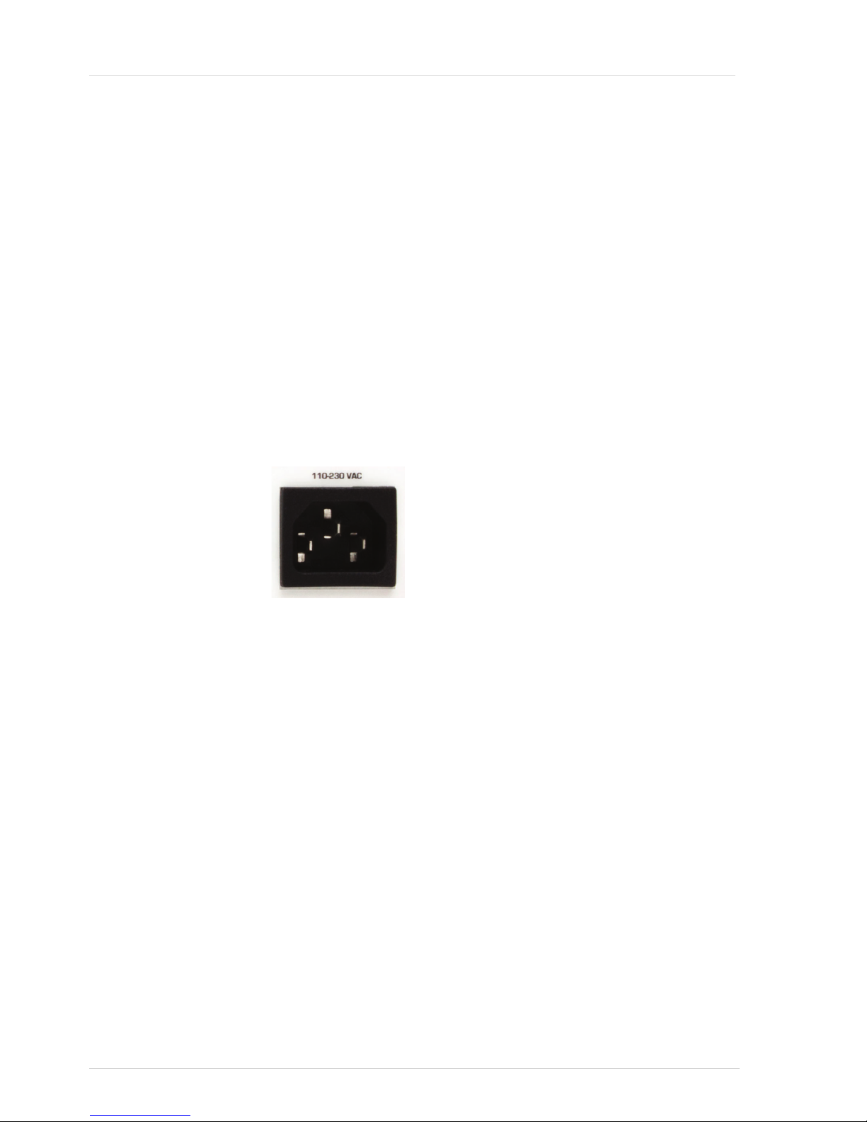
MS4000 Power Connector
The power connector is located at the front of the MS4000. A standard IEC C13 EU
power cable is supplied.
Figure 11 MS4000 AC Power Connector
Page 18
MS4000 Installation Guide
14
MS4000 Ground Connectors
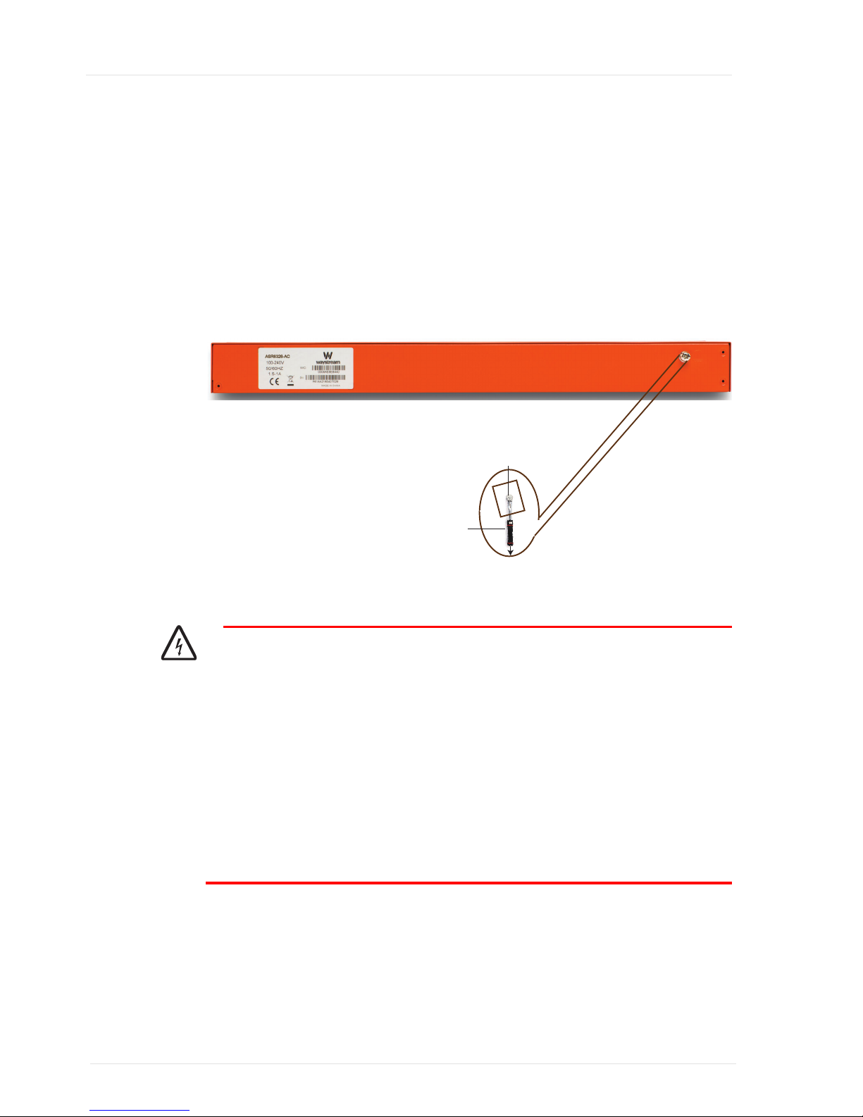
If required, ground connector screwholes are located at the front of the MS4000. Using
the ground screws and washer supplied, fasten the ground cable to the casing in the
following way:
1. Loosen the ground terminal screw
2. Insert an earthing wire connected to earth
3. Tighten screw and check that the earthing wire is securely fixed
Figure 12 MS4000 Ground Screws
Warning
• Connect the switch casing to earth before the switch is powered on for the first time,
• Proper grounding (connection to earth) is very important to protect the switch from
bad effects of external noise and to reduce the risk of electrocution in the event of a
direct lightning strike.
• For removal of the switch, disconnect the earthing wire after the power is switched
off and all other cables are disconnected.
• For the earthing wire, green and yellow insulation is required and the crosssectional
area of the conductor must not be less than 0.75 mm2 or 18 AWG.
Screw
To Earth
Earthing Wire
Page 19

15
Installing the MS4000
Tools Required
The MS4000 does not include any tools required to install the units. Appropriate
screwdrivers, ratchets etc. must be obtained elsewhere.
To complete this installation, the following extra materials are also needed:
• 10GigabitEthernet (SFP+) or GigabitEthernet (SFP) modules for uplink ports
• 12 patch cables, fibre for uplink ports
• GigabitEthernet SFP modules (depending on model)
• 124 patch cables, UTP/STP or SC/LC fibre for downlink ports (depending on
model)
Safety Guidelines
Follow these guidelines to ensure the required level of safety.
General Safety
• Keep the chassis area clear and dustfree during, and after, installation
• Do not wear loose clothing or jewellery that could get caught in the chassis. Fasten
your tie or scarf and roll up your sleeves.
• Wear safety glasses if you are working under any conditions that might be hazardous
to your eyes.
• Do not perform any action that creates a potential hazard to people or that makes
the equipment unsafe.
• Disconnect all power by turning off the power and unplugging the power cord
before installing or removing a chassis or working near power supplies.
• Do not work alone if potentially hazardous conditions exist.
• Never assume that power is disconnected from a circuit; always check the circuit
first.
Page 20

MS4000 Bootloader User Guide
16
Operating Safety
• Electrical equipment generates heat. Ambient air temperature may not be adequate
to cool equipment to acceptable operating temperatures without adequate
circulation. Be sure that the room in which you choose to operate your system has
adequate air circulation.
• Ensure that the chassis cover is secure. The chassis design allows cooling air to
circulate effectively. An open chassis permits air leaks, which may interrupt and
redirect the flow of cooling air from internal components.
• Electrostatic discharge (ESD) can damage equipment and impair electrical circuitry.
ESD damage occurs when electronic components are improperly handled and can
result in complete or intermittent failures. Be sure to follow ESDprevention
procedures when removing and replacing components to avoid these problems.
• Wear an ESDprevention wrist strap, ensuring that it has good skin contact, If no
wrist strap is available, ground yourself by touching the metal part of the chassis.
• Periodically check the resistance value of the antistatic strap, which should be
between 1 and 10 megaohms (Mohms).
EMC Notice
This equipment has been tested and found to comply with the limits for a Class A
digital device, pursuant to EN 55022. These limits are designed to provide reasonable
protection against harmful interference when the equipment is operated in a
commercial environment. This equipment generates, uses, and can radiate radio
frequency energy and, if not installed and used in accordance with this document, may
cause harmful interference to radio communications. Operation of this equipment in
a residential area is likely to cause harmful interference in which case owners will be
required to correct the interference at their own expense.
Page 21

Installing the MS4000
17
Equipment List
The following table lists the typical quantities of items supplied with each MS4000
unit.
• MS4000 unit
• One (1) 180 cm EU power cable with mains plug
• One (1) 180 cm RS232 cable (DB9 female to RJ45)
• Rack kit (preinstalled) including ;
–Two (2) angle brackets
– Eight (8) screws for angle bracket
– Four (4)cage nuts and screws (M6) with plastic washers
• Grounding kit including:
– Two (2) screws for grounding (M5) with lock washers
Page 22
MS4000 Bootloader User Guide
18
MS4000 Environment
The MS4000 is designed to be mounted in a 19inch rack in a restricted access
location. For restricted access locations, the following applies:
• Access can only be gained by SERVICE PERSONS or by USERS who have been
instructed about the reasons for the restrictions applied to the location and about
any precautions that shall be taken
• Access is through the use of a TOOL or lock and key, or other means of security,
and controlled by the authority responsible for the location
The switch is designed to be mounted in a single shelf of a 19inch rack. The cooling
fans are located on the side of the of the unit so ventilation must be available to allow
free airflow so that the fans can maintain a persistent and satisfactory ambient
temperature.
Figure 13 MS4000 in Rack
For rack installations, the following considerations must be taken:
• Elevated Operating Ambient Temperature When installed in a closed or multi
unit rack assembly, the operating ambient temperature of the rack environment may
be greater than the room ambient. Therefore, consideration should be given to
installing the equipment in an rack environment compatible with the maximum
ambient temperature, refer=“MS4000 Product Description” on page 31.
• Reduced Air Flow Installation of the equipment in a rack should be such that the
amount of air flow required for safe operation of the equipment is not
compromised.
• Mechanical Loading Mounting of the equipment in the rack should be such that
a hazardous condition is not achieved due to uneven mechanical loading.
• Circuit Overloading Consideration should be given to the connection of the
equipment to the supply circuit and the effect that overloading of the circuits might
have on overcurrent protection and supply wiring. Appropriate consideration of
equipment nameplate ratings should be used when addressing this concern.
• Reliable Earthing Reliable earthing of rackmounted equipment should be
maintained. Particular attention should be given to supply connections other than
direct connections to the branch circuit (e.g. use of power strips).
Page 23
Installing the MS4000
19
Ventilation of MS4000
The MS4000 is cooled by three builtin fans. Ensure that air can flow freely from right
toleft in the cabinet. To extend the lifetime of the fans, ensure that the air is filtered
and free from dust particles.
Rack Installation of MS4000
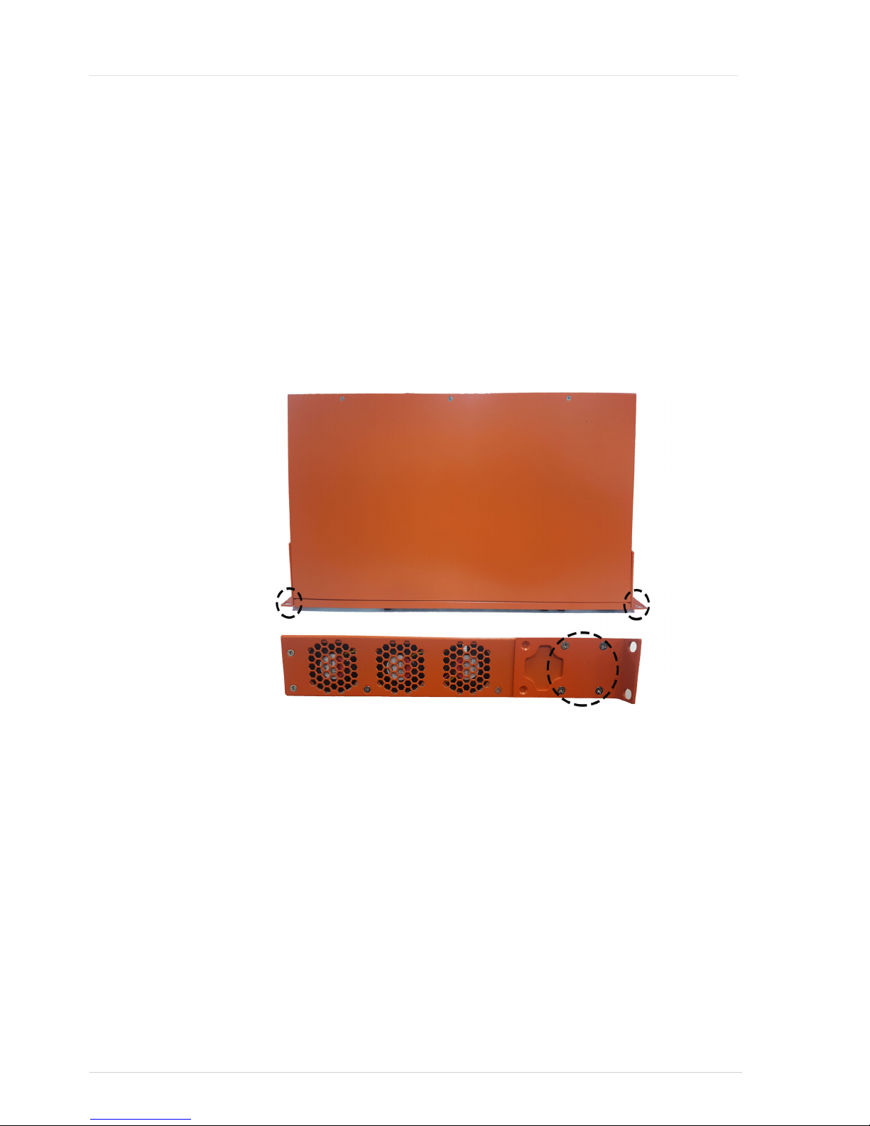
As shown in Figure 13, multiple MS4000 units can be mounted in a 19inch rack on
top of each other. All connectors are located in the front of the MS4000 for easy access.
The rack brackets are preattached for fast installation. When the switch is installed, the
front panel will be flush with the front of the rack frame, see Figure 14.
Figure 14 Default Rack Bracket on Switch
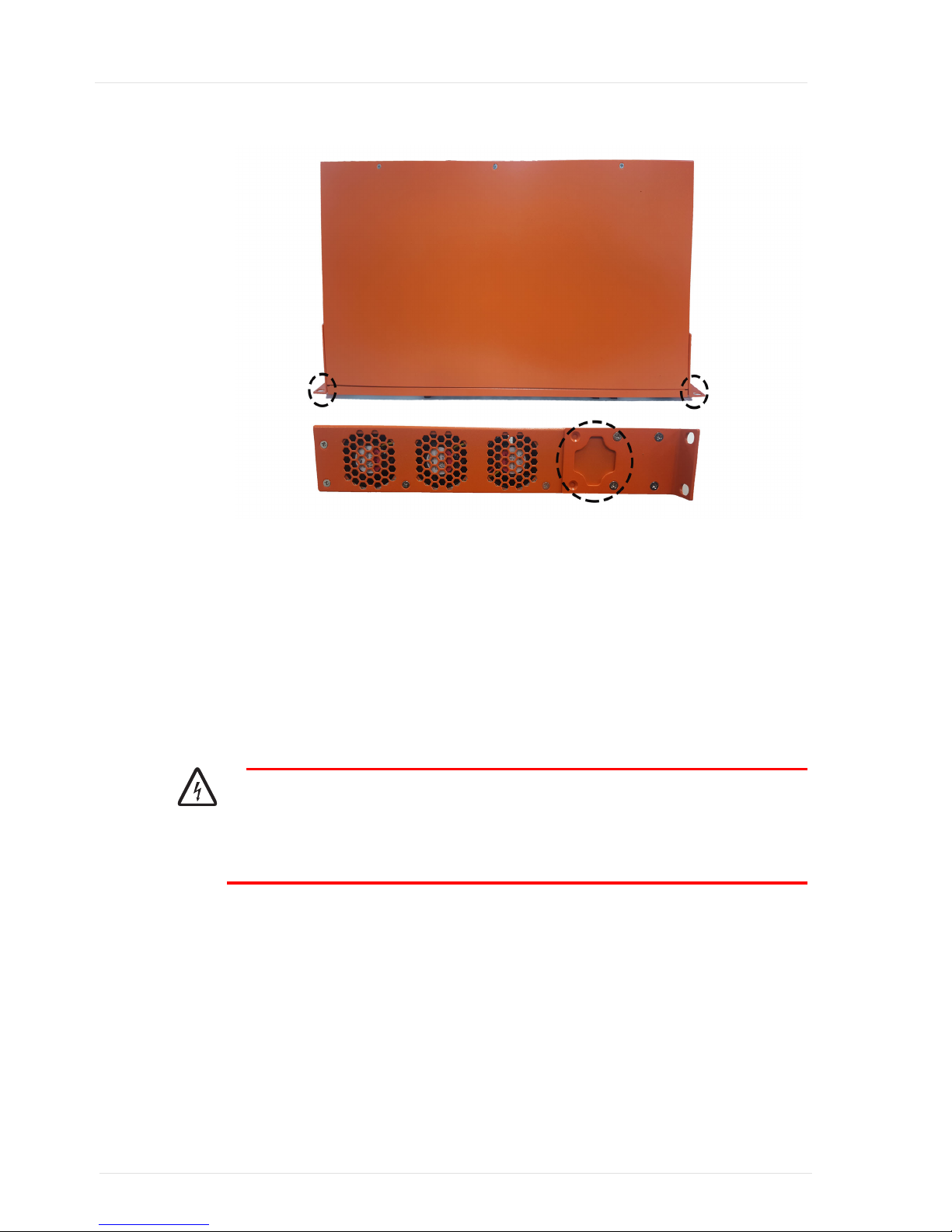
For cabinets with doors that require more space for cables etc in front of the unit, it is
possible to remove the four bracket screws and reposition the brackets using the extra
screwholes to provide 25 mm space in front of the switch, see Figure 15.
Page 24
MS4000 Bootloader User Guide
20
Figure 15 Rack Bracket Installed for Extra Space
To install the switch in the rack, hold the MS4000 firmly in position and use the
supplied screws and nut baskets to fix the unit in the 19inch rack space.
Connecting Power to the MS4000
The information below is valid for all MS4000 units.
The MS4000 runs on 110/240V 5060Hz AC. Installation of 110/220V mains power
outlets must be performed by a licensed electrician.
Warning
The MS4000 unit must be connected to ground before power supply units,
computers or other electrical or electronic equipment is connected to the MS4000
(including the serial console port).
Page 25

Installing the MS4000
21
Power ON
When the mains power is connected to the MS4000, the MS4000 will automatically
boot and attempt to establish the uplink connection with the network.
To power up the MS4000, do the following:
1. Connect the mains power cable to the MS4000 power connector.
2. Connect the mains power cable to the power socket.
3. If there is an ON/OFF switch, then flip the ON/OFF switch to ON.
The MS4000 power LED will now light up.
Note: The fans take 56 seconds before starting.
Installing SFP Modules
The MS4000 is designed to use Small Form Factor Pluggables (SFP+) modules for 10
GigabitEthernet uplinks. For information about insertion and removal of SFP+
modules and important safety information, please refer “SFP Products” on page 33.
Connecting the MS4000 to the Network
In most network topologies, the 10 GigabitEthernet SFP+ modules will be used as
uplinks, connecting the MS4000 to the network.
Connecting Uplink Interfaces
To connect the uplink interfaces to the switch:
1. Select the appropriate patch cables for the SFP modules installed.
2. Remove dust cover on SFP and connect the patch cable to the SFP
3. Connect the patch cable to the network fibre patch panel or fibre connector
If the switch establishes an uplink, connection the uplink LED will light up.
Page 26

MS4000 Bootloader User Guide
22
Connecting Downlink Interfaces
Determine what type of downlink interfaces are used by the unit. Depending on the
switch model, different connectors and cable types are used.
1. Connect the patch cables to the MS4000 interfaces
2. Connect the patch cable to the network patch panel
If the MS4000 gets a configuration and there are client devices connected to the
subscriber side of the connection, the LED panel will indicate that link is present on
the corresponding MS4000 downlink interface.
Table 4 Downlink Interfaces
Model Patch cable type Connector type
MS4126 20 Cat5e or Cat6 Twisted Pair (TP) RJ45
MS4026 20 SFP SFP (see “SFP Products” on page 33
Page 27
23
Checking the Switch Installation
The MS4000 router has a console interface that is used to view configuration
information when the switch is running. During the boot process, the switch outputs
information about the boot progress, and if any problems are encountered.
Figure 16 Console Interface
To connect to the console port, you need the RJ45 to 9 pin DSub cable supplied with
the unit.
Connecting to the Console Interface Port
1. Connect your terminal to the console port using the supplied cable.
Configure your terminal software using the following settings:
– 8 data bits, no parity and 1 stop bit (8N1)
– No flowcontrol or hardware flowcontrol (RTS/CTS)
– 115200 bps send rate
Page 28

MS4000 Bootloader User Guide
24
The Boot Process
When the power is first turned on, the MS4000 immediately starts the bootloader
software. The bootloader performs basic system initialization, decompresses, and runs
the iBOS software image that is stored on flash memory. The boot process can be
followed on the console.
The Bootloader locates a bootable image either on the flash memory (if it exists), or in
the network if BOOTP options provided to the switch by the network so indicate. The
image is compressed to conserve file system space, and must therefore be decompressed
when read into memory. The Bootloader displays the following message when it is de
compressing the iBOS image:
Decompressing ibos-ms4k-6.3.0-ED-R.bz2 (press any key to abort)
Note:
The local filename of the image being decompressed is displayed, e.g. the image
filename is ibosms4k6.3.0EDR.bz2.
When the iBOS image has been loaded into RAM, the Bootloader will start the main
software. The following message is displayed:
Running ELF executable at address: 0x80200000
Troubleshooting the Bootloader
When a terminal is connected to the switch console port, pressing any key aborts the
boot process and enters the bootloader command line interface. Situations where the
bootloader fails to complete the boot process are:
• If the boot process is looping, it may be necessary to download new software or to
make changes to the boot configuration if the switch is not able to complete the boot
process.
• If there is no valid iBOS image on the flash file system, the boot process will
continue to loop until there is an active uplink and contact is established with a boot
server.
No Uplink during Boot
If the boot process is looping because of no link on the uplink interfaces, the bootloader
will print the following to the terminal:
..
Autoboot in progress (press any key to abort).
Scanning boot image information on flash.
No image found.
Trying BOOTP over tengigabitethernet1 and tengigabitethernet2.
No link on tengigabitethernet1.
No link on tengigabitethernet2.
BOOTP failed.
Retrying BOOTP (press any key to abort).
Trying BOOTP over tengigabitethernet1 and tengigabitethernet2.
Page 29

Checking the Switch Installation
25
No link on tengigabitethernet1.
No link on tengigabitethernet2.
BOOTP failed.
Retrying BOOTP (press any key to abort).
...
The example above shows that no link was detected on the tengigabitethernet1 or
tengigabitethernet2 interfaces. Check that the SFP is properly inserted and that the
fiber is connected. If no problem can be found in the connections the probable cause
is the other end of the fiber.
No valid iBOS Image during Boot
If a default image is found in the flash file system and one BOOTP attempt fails to get
a new image name from the boot server, the selected image is booted (or if it is damaged
the newest image found on the flash is used instead). The following text is printed on
the terminal
..
Autoboot in progress (press any key to abort).
Scanning boot image information on flash.
Found image version ibos-ms4k-6.3.0-ED-R
Trying BOOTP over tengigabitethernet1 and tengigabitethernet2.
BOOTP failed.
Decompressing ibos-ms4k-6.3.0-ED-R (press any key to abort).
...
If no image is selected for default boot, but at least one image is found and no
connectivity with boot server is acquired within ten BOOTP attempts, the newest
image found on the flash is booted. The following text will be printed on the terminal
...
Autoboot in progress (press any key to abort).
Scanning boot image information on flash.
Found fallback image version ibos-ms4k-6.0.1-ED-R
Trying BOOTP over tengigabitethernet1 and tengigabitethernet2.
BOOTP failed.
Retrying BOOTP, 9 attempts left.
...
Retrying BOOTP, 2 attempts left.
Trying BOOTP over tengigabitethernet1 and tengigabitethernet2.
BOOTP failed.
Retrying BOOTP, 1 attempts left.
Trying BOOTP over tengigabitethernet1 and tengigabitethernet2.
BOOTP failed.
No file to boot.
Trying to find another image to boot.
Booting ibos-ms4k-6.3.0-ED-R.
Decompressing ibos-ms4k-6.3.0-ED-R (press any key to abort).
...
For more information on the Bootloader CLI, refer “MS4000 Bootloader User Guide”.
Page 30

MS4000 Bootloader User Guide
26
Troubleshooting iBOS
The iBOS software is the switch operating system that enables services and also has
internet connection features. When connected to the switch using the console port or
the management port, an iBOS command line interface appears after a successful boot
process.
Access to iBOS command line normally requires login. There is no default username
or password configured, and if the switch is unconfigured simply press the Enter key
when prompted for username and password.
Note: If local or remote user authentication has been configured in the switch, the correct
username and password must be used to gain access to the command line interface
via the console port.
The command line interface displays the switch hostname (if configured), the CSAR
connection status, the system uptime etc.
Check System
To display the system information, use the show version command. The information dis
played includes the version of iBOS running in the system, the system hostname and
uptime, the model and characteristics of the switch including the serial number and
other device information.
Example 1 show version
ms> show version
Intelligent Broadband Operating System (iBOS), Version 6.3.0-ED-R
Copyright (c) 2001-2016 by Waystream AB
Routing Engine Copyright (C) 2001-2009 IP Infusion, Inc.
Compiled Tue Apr 30 16:31:05 HKT 2013 by builder
Source ID: e55c2413110ac36de6ee61f1964230754a72514e
ms uptime is 0 minutes
Last boot: warm start
System image file is "ibos-ms4k-6.3.0-ED-R.bz2", version ibos-ms4k-
6.3.0-ED-R
System: MS4026-AC, 2 1/10GE SFP+, 20 100/1000 SFP Slots, 4 BaseTX/
SFP combo, AC
Bootloader version: msboot-ms4k-3.6.1-R
PCBA revision: 0.2
Product ID: 791-1230
Serial number/Base MAC address: 0008AE8709A0
Processor: CN6230 [pass 2.2] (mipseb)
262144K bytes CPU RAM
ms>
Page 31

Checking the Switch Installation
27
Check Available PFDP Devices
The PacketFront Device Protocol is exchanged between all PFNP products. The com
mand show pfdp neighbours displays a summary of all known PFDP devices (ASR, SE,
DRG etc.) that are connected this switch.
Example 2 show pfdp neighbours
ms> show pfdp neighbours
gigabitethernet23 with 1 neighbour(s):
"DRG800" running "drgosl-drg800-1.1.0-RC3" on model "DRG886"
remote interface uplink1, last activity 0s ago, unidirectional
gigabitethernet24 with 1 neighbour(s):
"DRG508s_MK1" running "DMA0081-R2N20" on model "DRG508s_MK1"
remote interface wan1, last activity 53s ago, unidirectional
tengigabitethernet1 with 1 neighbour(s):
"Small-BTU1-2" running "iBOS 3.21.4-ED-R" on model "switch4124C"
remote interface gigabitethernet2, last activity 22s ago,
bidirectional
tengigabitethernet2 with 1 neighbour(s):
"Small-BTU1-8" running "iBOS 6.1.0-ED-RC2" on model "switch5124CCO"
remote interface gigabitethernet1, last activity 28s ago,
bidirectional
ms>
Check SFP Interfaces
To examine the uplink gigabit interface sfp statistics, use the iBOS command show
interface sfp
for the uplink interface. (Pay special attention to the TX/RX input/output
power details).
Example 3 show interface sfp
ms# show interface tengigabitethernet1 sfp
Small Form-factor Pluggable (SFP) at tengigabitethernet1
LC connector
10000-SR capable
64B/66B encoding, nominal bitrate: 10300 Mbps
Supported links
50um multi mode fiber: 80 m
62.5um multi mode fiber: 30 m
Laser wavelength: 850 nm
Diagnostics Normal Warning
Entity Status Unit Current Low High Low
High
------------------------------------------------------------------
--------
Operating temp: OK C 40.88 -3.00 73.00 -5.00
75.00
Page 32

MS4000 Bootloader User Guide
28
Supply voltage: OK V 3.27 3.14 3.47 2.97
3.63
TX current: OK mA 5.30 2.00 11.00 1.00 12.00
TX output power: OK mW 0.55 0.32 0.66 0.25
0.83
RX input power: ALRM(L) mW 0.00 0.02 0.79 0.01
1.00
ms
Check the Uplink Interface
To check that the uplink interface gets an IP address from the network boot server, use
the command show ip bootp.
Example 4 show ip bootp
ms> show ip bootp
BOOTP Client state: Standby
mode: Persistent
serial: 0008.ae86.0440
protos: http,tftp
version: ibos-ms4k-6.3.0-ED-R
Interface tengigabitethernet2
BOOTP mode is Standby, interface is Up
Last assigned: 10.130.1.29/30 gateway 0.0.0.0 server 10.66.110.10
(1D17h49m41s
ago)
Packet counters:
1 sent, 1 received
0 dropped due to erroneous data
0 dropped because we couldn't comply
0 with matching addresses, 1 used assignments
Interface tengigabitethernet1
BOOTP mode is Standby, interface is Up
Last assigned: 10.130.1.2/30 gateway 10.130.1.1 server
10.66.110.10 (1D17h49m4
0s ago)
Packet counters:
1 sent, 1 received
0 dropped due to erroneous data
0 dropped because we couldn't comply
0 with matching addresses, 1 used assignments
ms#
Page 33

Checking the Switch Installation
29
Check VLAN Interfaces
By default, the uplink interfaces are assigned to VLAN1 and all downlink interfaces are
assigned to VLAN2. To check the VLAN connections, use the command show vlan
Example 5 show vlan
ms# sh vlan
VLAN Interfaces
-----------------------------------------------------------------
1 tengigabitethernet1 tengigabitethernet2
2 gigabitethernet1 gigabitethernet2 gigabitethernet3
gigabitethernet4 gigabitethernet5 gigabitethernet6
gigabitethernet7 gigabitethernet8 gigabitethernet9
gigabitethernet10 gigabitethernet11 gigabitethernet12
gigabitethernet13 gigabitethernet14 gigabitethernet15
gigabitethernet16 gigabitethernet17 gigabitethernet18
gigabitethernet19 gigabitethernet20 gigabitethernet21
gigabitethernet22 gigabitethernet23 gigabitethernet24
ms#
Check CSAR
To check CSAR connection for a BECS3 network and to ensure there is a service pro
vision, use the command show csar.
Example 6 show csar
MS4k# show csar
Server Address State Flags
------------------------------------------------------------------
-------------em-ibos@small-.. 10.66.110.10 Up Connected,Learned
Active server: em-ibos@small-cell-1-p
Page 34

MS4000 Bootloader User Guide
30
Page 35

31
Appendix A – MS4000 Product Description
This appendix describes product details for specific models that may be required while
installing the MS4000.
MS4000 Interfaces
• Two (2) SFP+ module slots for 10 GigabitEthernet uplink ports (all models)
• 24 (24) SFP module slots for GigabitEthernet downlink ports (4026 only)
• Two (2) RJ45 combo ports for GigabitEthernet downlink ports 2124 (4026 only)
• 24 (24) RJ45 GigabitEthernet downlink ports (4126 only)
• Two (2) SFP module slots for GigabitEthernet combo ports 2124 (4126 only)
Interface Specification
For a detailed specification and pictures of the interfaces for each specific model, refer
“Product Overview” on page 5.
Page 36

MS4000 Installation Guide
32
Technical Data
Physical Dimensions
Table 5 Physical Dimensions
Power and Safety
• Single power input 100 – 240V, 50 – 60 Hz, compliant with ETSI EN 300132
V2.1.1 Part1.
• CE mark
• IEC/EN/UL 60950
• IEC/EN/UL 60826
• CB certificate
• ETSI EN 300386
• FCC Part 15 Subpart B
• RoHS directive 2002/95/EC
Environmental
All MS4000 models:
• Operating temperature: 0° to 45° C
• Storage temperature: 10° to 70° C
• Operating humidity: 5% to 95%, noncondensing
• Heat dissipation: max 46 watts
MS4000CO
H*W*D (mm) = 43 x 441 x 240
Weight: 4 kg
Standard 19inch rack mounting
Page 37
33
Appendix B – SFP Products
Overview
The Waystream SFP (Small Formfactor Pluggable) GigabitEthernet interfaces are a
series of optical transceiver modules that enable the switch to be fitted with suitable
network interfaces for different needs.
Using standardized safety requirements, the modules are certified for use together with
the Waystream switch series switches.
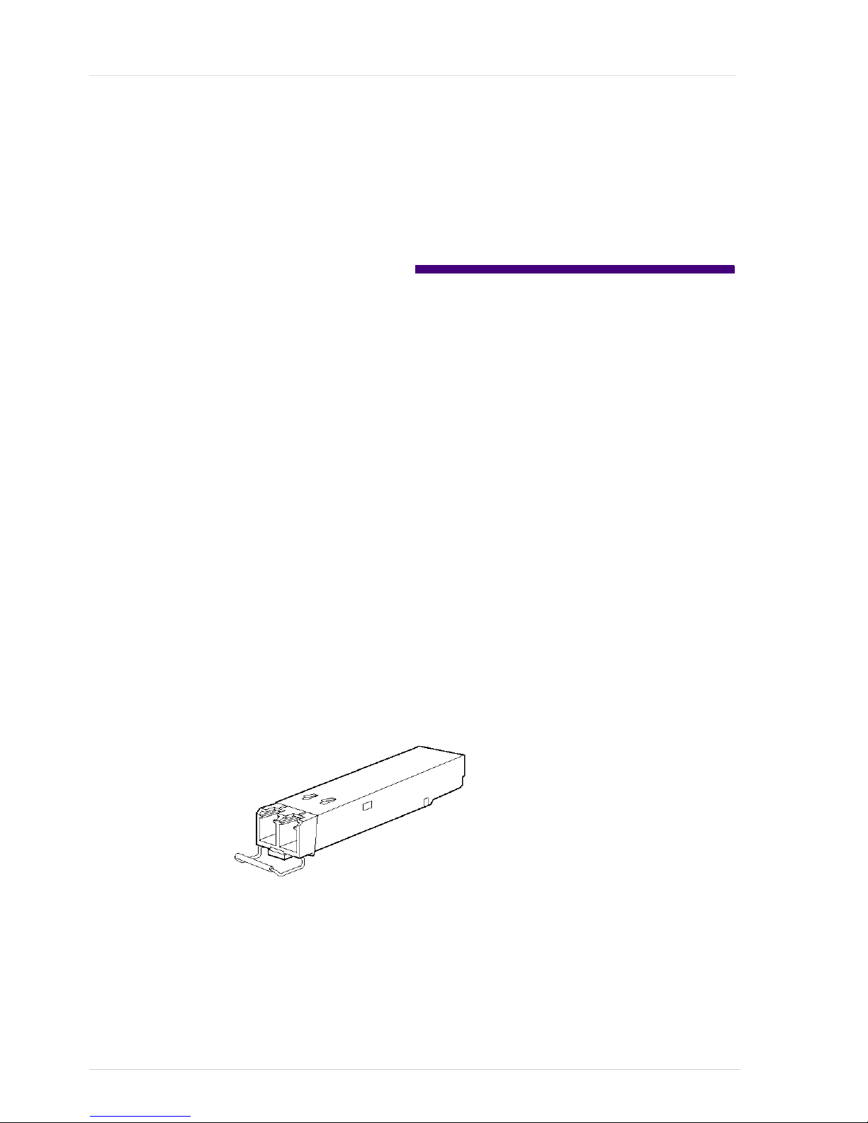
Waystreamapproved SFP modules have a serial EEPROM that contains the module
serial number, the vendor name and ID, a unique security code, and cyclic redundancy
checksum (CRC).
This manual does not describe the full product specifications for each SFP module.
Models and data for Waystream SFPs is listed in separate data sheets. The SFPs named
in this document are used for examples only, and are not ranked in any preferential
order.
All SFPs have baleclasp latches for safe operation.
Figure 17 SFP with baleclasp latch
Page 38

MS4000 Installation Guide
34
Table 6 PFNP SFP Products
Note: The selection of Waystream SFP products is being constantly improved, please
contact your local sales representative for an uptodate list of PFNP approved
SFPs.
When the SFP is inserted in the switch, the switch software reads the EEPROM to
check the serial number, vendor name and ID, and recomputes the security code and
CRC.
The SFP also provides link status information and other valuable statistics to determine
the operation and quality of the connection to the adjacent device. This information is
displayed using the iBOS command show interface sfp.
Caution
Use of nonWaystream approved SFPs will void the product warranty.
Waystream SFP
Product Name
Wavelength Connector Fibre type Speed
(Mbps)
SFP1000BASEBXD TX:1490nm
RX:1310nm
SC Simplex Single mode 1000
SFP1000BASEBXU TX:1310nm
RX:1490nm
SC Simplex Single mode 1000
SFP1000BASEBX10
D1550LC
TX:1550nm
RX:1310nm
LC Simplex Single mode 100/1000
SFP1000BASEBX10
D1550SC
TX:1550nm
RX:1310nm
SC Simplex Single mode 100/1000
SFP1000BASEBX10
U1550LC
TX:1310nm
RX:1550nm
LC Simplex Single mode 100/1000
SFP1000BASEBX10
U1550SC
TX:1310nm
RX:1550nm
SC Simplex Single mode 100/1000
SFP1000BASELX 1310 nm LC Duplex Single mode 1000
SFP1000BASELXM 1310nm LC Duplex Single mode 100/1000
SFP1000BASESX 850 nm LC Duplex Multimode 1000
SFP1000BASESXM 850nm LC Duplex Multimode 100/1000
SFP1000BASET N/A RJ45 N/A 10/100/1000
SFP1000BASEZX 1550 nm LC Duplex Single mode 1000
SFP10GELR 1310nm LC Duplex Single mode 10000
SFP10GESR 850nm LC Duplex Multimode 10000
Page 39
35
Safety
Before installing an SFP module or attempting to handle a PFNP broadband router
equipped with SFP slots, you should read and understand the safety information in this
document. Laser warnings only apply to fiberoptic SFP modules.
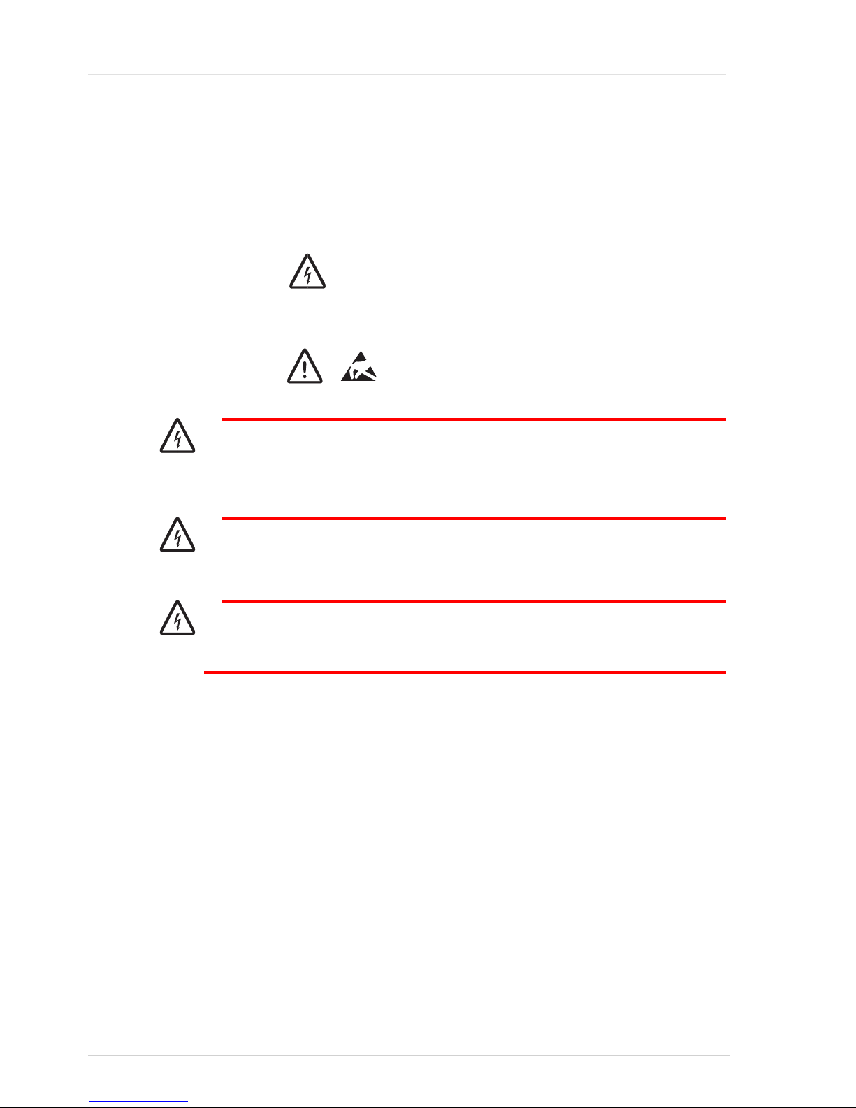
Figure 18 Warning Symbol
Figure 19 Caution Symbols
Warning
Class 1 laser product. Do not position your eye directly in front of the SFP if the
dust plugs are not installed!
Warning
Laser beam is exposed when dust plug is removed and fiber not installed.
Warning
Only trained staff should install or replace SFPs.
Page 40
MS4000 Installation Guide
36
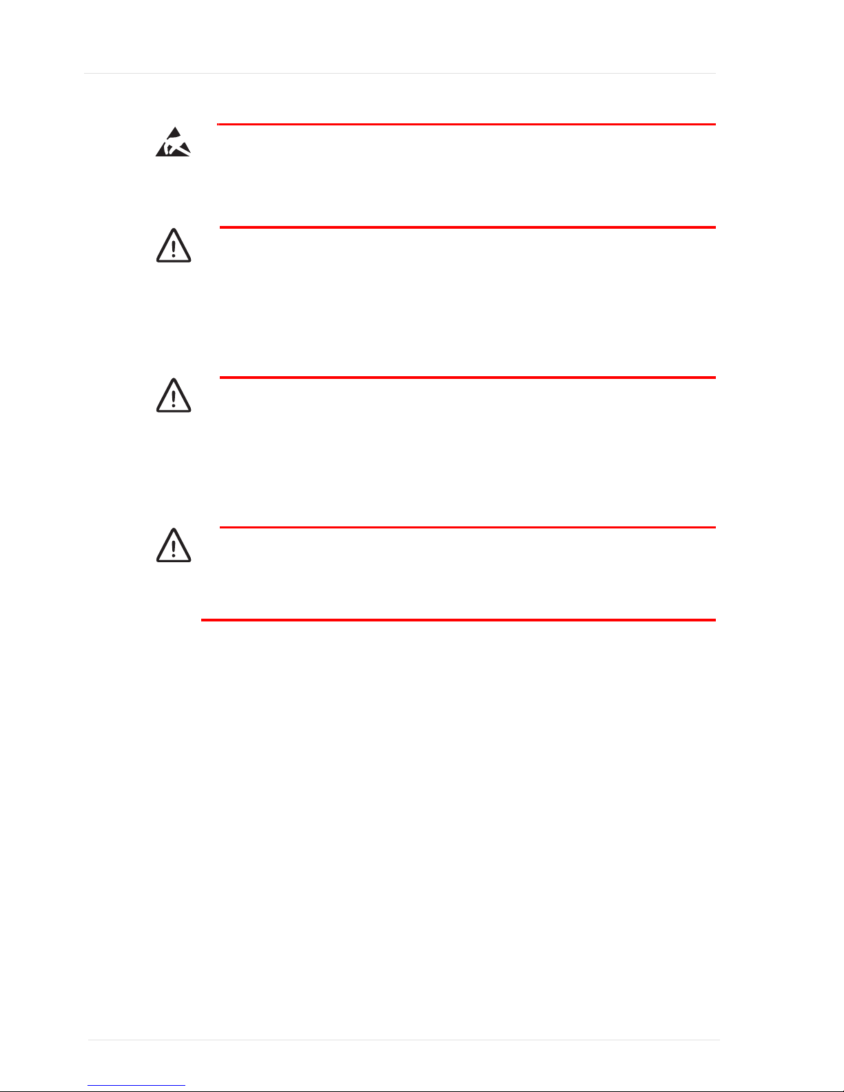
Caution
SFPs are electronic devices and sensitive to static electricity. Always use an ESD
preventive wrist strap when handling an SFP. ESD damages can cause performance
and lifetime degradation.
Caution
Protect your fiberoptic components, like SFPs and cables, by inserting clean dust
plugs when not connected to other equipment. Clean the optic components
whenever you intend to connect them. Avoid getting dust and other contaminants
into the optical receptacles, as fibre optics do not work correctly when obstructed
with dust.
Caution
When using shorter distances of singlemode fiber cable, you may need to insert an
inline optical attenuator in the link to avoid overloading the receiver. When the
fiberoptic cable is less than 20 km and the link budget is more than 15dB, insert a
5 to 10 dB optical attenuator between the fiberoptic cable plant and the receiving
port of the SFP.
Caution
Under no circumstances should the SFP insertion or removal require physical force.
handling. Always be gentle and use only your thumb and index finger!
Page 41

37
Insertion and Removal
When inserting or removing SFPs, always observe the following precautions:
• Attach an ESDpreventive wrist strap to your wrist and to a bare metal surface on
the chassis or the common ground connector at the back of the module.
• Hold the SFP modules by the side only and do not touch the connectors on the
insertion end of the module
Note: For other SFPs, please see the manufacturer instructions for installation and
removal.
Inserting an SFP module
1. Align the SFP module in front of the SFP slot. Note that the top side (with PFNP
sticker) faces up for upper row slots but faces down for lower row slots. This allows
more space for connecting the cables to the SFPs.
2. Carefully slide the SFP module into the slot until you feel the connector on the
module snap into place.
3. Push the baleclasp latch up until it locks the SFP in position.
4. Remove the dust plugs from the cable and the SFP. Clean the connectors and the
SFP with dedicated fibre cleaning tools and carefully insert the cable(s) until they
snap into place.
5. The SFP is now ready. The SFP state is indicated by the port LED
Note: Do not remove the dust plugs from the fiberoptic SFP module port or the rubber
caps from the fiberoptic cable until you are ready to connect the cable. The plugs
and caps protect the SFP module ports and cables from contamination and
ambient light.
Removing an SFP Module
1. Disconnect the cable from the SFP module and reinstall the dust plugs.
2. All Waystream SFPs have baleclasp latches. Gently pull the baleclasp latch out and
down until the SFP releases.
Note: For other SFPs, please see the manufacturer instructions for installation and
removal
3. Place the removed SFP module in an antistatic bag or other protective environment.
Page 42

MS4000 Installation Guide
38
Page 43

Page 44

 Loading...