

Page 1

MPC480 Installation Guide
Page 2

Page 3

MPC480 Installation Guide
Page 4

MPC480 Installation Guide
WS-DOC-MPC480-INSTALL. Published June 14, 2016.
Copyright and Legal notice
Copyright 2015 Waystream AB. Alll rights reserved.
MPC, iBOS, and Bootloader are tradenames of Waystream.
All other trademarks, service marks and trade names are proprietary to their respective owner.
iBOS, the Bootloader, program models and other software content and this documentation (“the Intellectual
Property Rights”) are protected by the Swedish Copyright Act (Sw: Upphovsrättslagen) and, if applicable,
the Swedish Patents Act (Sw: Patentlagen). All and any copying and distribution of the Intellectual Property
Rights, without authorization by Waystream is prohibited. The prohibition includes every form of reproduction
and distribution.
Every effort was made to ensure that the information in this document was complete and accurate at the
time of printing. However, information is subject to change without notice. Waystream assumes no liability
for damages incurred directly or indirectly from errors, omissions or discrepancies between the software and
this document.
Purchasers, licensees and users accept and acknowledge that the products contain components (including
components carrying certain firmware) and combinations of components that constitute trade secrets protected by Waystream or its partners. Purchasers, licensees and users warrant that the delivered products
will not be opened or dismantled, copied, altered or in any other way modified. Furthermore, purchasers,
licensees and users agree not to attempt to reverse engineer, disassemble, modify, translate, create derivate
works, rent, lease, loan, or without written permission distribute or sublicense the software, in whole or in
part.
The products and its hardware, firmware and software, including technical data, may be subject to EU and
U.S export control laws, including the U.S Export Administration Act and its associated regulations and the
International Traffic in Arms Regulations administerd by the US Department of State, and may be subject
to export or import regulations in other countries. Purchasers and licensees agree to comply strictly with all
such regulations and acknowledges that it has the responsibility to obtain licenses to export, re-export, or
import hardware, firmare and software.
Purchasers and licensees are not entitled to, and Waystream is not in any event liable to pay, compensation
for damages which delivered products or software has caused to other property or to persons or any other
consequential damages, including but not limited to loss of profit, loss of production or any other indirect
damages.
Page 5

Contents
Introduction. . . . . . . . . . . . . . . . . . . . . . . . . . . . . . . . . . . . . . . . . . . . . . . . . . . . . . . . . . 1
Getting started . . . . . . . . . . . . . . . . . . . . . . . . . . . . . . . . . . . . . . . . . . . . . . . . . . . . . . . 3
Overview. . . . . . . . . . . . . . . . . . . . . . . . . . . . . . . . . . . . . . . . . . . . . . . . . . . . . . . . . . . . . . . . . . . . .3
MPC480 packages . . . . . . . . . . . . . . . . . . . . . . . . . . . . . . . . . . . . . . . . . . . . . . . . . . . . . . . . . . . . .4
Installing MPC480 chassis. . . . . . . . . . . . . . . . . . . . . . . . . . . . . . . . . . . . . . . . . . . . . . . . . . . . . . . .5
Attach rack brackets to MPC480 . . . . . . . . . . . . . . . . . . . . . . . . . . . . . . . . . . . . . . . . . . . . . . . .6
Mount chassis in rack cabinet . . . . . . . . . . . . . . . . . . . . . . . . . . . . . . . . . . . . . . . . . . . . . . . . . .6
Ground chassis to rack . . . . . . . . . . . . . . . . . . . . . . . . . . . . . . . . . . . . . . . . . . . . . . . . . . . . . . .8
Installing mainboard . . . . . . . . . . . . . . . . . . . . . . . . . . . . . . . . . . . . . . . . . . . . . . . . . . . . . . . . . . . .8
Installing linecard . . . . . . . . . . . . . . . . . . . . . . . . . . . . . . . . . . . . . . . . . . . . . . . . . . . . . . . . . . . . . .9
Installing power supply unit(s) . . . . . . . . . . . . . . . . . . . . . . . . . . . . . . . . . . . . . . . . . . . . . . . . . . . .10
Connecting power to the MPC . . . . . . . . . . . . . . . . . . . . . . . . . . . . . . . . . . . . . . . . . . . . . . . . .11
Setup the MPC480 . . . . . . . . . . . . . . . . . . . . . . . . . . . . . . . . . . . . . . . . . . . . . . . . . . . . . . . . . . . .11
Log in to the MPC480 operating system . . . . . . . . . . . . . . . . . . . . . . . . . . . . . . . . . . . . . . . . .12
Set the login password . . . . . . . . . . . . . . . . . . . . . . . . . . . . . . . . . . . . . . . . . . . . . . . . . . . . . .12
Set IP address on management interface. . . . . . . . . . . . . . . . . . . . . . . . . . . . . . . . . . . . . . . . .12
Save your changes . . . . . . . . . . . . . . . . . . . . . . . . . . . . . . . . . . . . . . . . . . . . . . . . . . . . . . . . .13
Check installed ports. . . . . . . . . . . . . . . . . . . . . . . . . . . . . . . . . . . . . . . . . . . . . . . . . . . . . . . . . . .13
Configuring the MPC480. . . . . . . . . . . . . . . . . . . . . . . . . . . . . . . . . . . . . . . . . . . . . . . 15
Connecting to the console interface port . . . . . . . . . . . . . . . . . . . . . . . . . . . . . . . . . . . . . . . . . . . .15
The bootloader process . . . . . . . . . . . . . . . . . . . . . . . . . . . . . . . . . . . . . . . . . . . . . . . . . . . . . . . . .15
Connect network interfaces. . . . . . . . . . . . . . . . . . . . . . . . . . . . . . . . . . . . . . . . . . . . . . . . . . . . . .16
Troubleshooting iBOS . . . . . . . . . . . . . . . . . . . . . . . . . . . . . . . . . . . . . . . . . . . . . . . . . . . . . . . . . .16
Check system software . . . . . . . . . . . . . . . . . . . . . . . . . . . . . . . . . . . . . . . . . . . . . . . . . . . . . .16
Check installed ports. . . . . . . . . . . . . . . . . . . . . . . . . . . . . . . . . . . . . . . . . . . . . . . . . . . . . . . . . . .17
MPC480 Overview . . . . . . . . . . . . . . . . . . . . . . . . . . . . . . . . . . . . . . . . . . . . . . . . . . . . 19
Restricted access location. . . . . . . . . . . . . . . . . . . . . . . . . . . . . . . . . . . . . . . . . . . . . . . . . . . . . . .19
Ventilation of MPC480 . . . . . . . . . . . . . . . . . . . . . . . . . . . . . . . . . . . . . . . . . . . . . . . . . . . . . . .20
MPC480 components . . . . . . . . . . . . . . . . . . . . . . . . . . . . . . . . . . . . . . . . . . . . . . . . . . . . . . . . . .21
MPC chassis . . . . . . . . . . . . . . . . . . . . . . . . . . . . . . . . . . . . . . . . . . . . . . . . . . . . . . . . . . . . . .21
Installation kit . . . . . . . . . . . . . . . . . . . . . . . . . . . . . . . . . . . . . . . . . . . . . . . . . . . . . . . . . . . . .24
MPC mainboard. . . . . . . . . . . . . . . . . . . . . . . . . . . . . . . . . . . . . . . . . . . . . . . . . . . . . . . . . . . .25
MPC480 linecard. . . . . . . . . . . . . . . . . . . . . . . . . . . . . . . . . . . . . . . . . . . . . . . . . . . . . . . . . . .26
MPC480 PSU. . . . . . . . . . . . . . . . . . . . . . . . . . . . . . . . . . . . . . . . . . . . . . . . . . . . . . . . . . . . . .26
MPC480 Front Panels . . . . . . . . . . . . . . . . . . . . . . . . . . . . . . . . . . . . . . . . . . . . . . . . . . . . . . . . . .28
Mainboard front panel . . . . . . . . . . . . . . . . . . . . . . . . . . . . . . . . . . . . . . . . . . . . . . . . . . . . . . .28
Mainboard LED . . . . . . . . . . . . . . . . . . . . . . . . . . . . . . . . . . . . . . . . . . . . . . . . . . . . . . . . . . . .28
Mainboard ports . . . . . . . . . . . . . . . . . . . . . . . . . . . . . . . . . . . . . . . . . . . . . . . . . . . . . . . . . . .29
Console and Ethernet management ports . . . . . . . . . . . . . . . . . . . . . . . . . . . . . . . . . . . . . . . .30
Linecard front panel . . . . . . . . . . . . . . . . . . . . . . . . . . . . . . . . . . . . . . . . . . . . . . . . . . . . . . . .30
Page 6

MPC480 power connectors . . . . . . . . . . . . . . . . . . . . . . . . . . . . . . . . . . . . . . . . . . . . . . . . . . . . . .30
MPC480 rear panel . . . . . . . . . . . . . . . . . . . . . . . . . . . . . . . . . . . . . . . . . . . . . . . . . . . . . . . . . . . .31
Fan trays. . . . . . . . . . . . . . . . . . . . . . . . . . . . . . . . . . . . . . . . . . . . . . . . . . . . . . . . . . . . . . . . .31
Power button. . . . . . . . . . . . . . . . . . . . . . . . . . . . . . . . . . . . . . . . . . . . . . . . . . . . . . . . . . . . . .33
Power modules . . . . . . . . . . . . . . . . . . . . . . . . . . . . . . . . . . . . . . . . . . . . . . . . . . . . . . . . . . . .33
Appendix A – MPC480 Technical Specification 35
Physical . . . . . . . . . . . . . . . . . . . . . . . . . . . . . . . . . . . . . . . . . . . . . . . . . . . . . . . . . . . . . . . . . . . .35
Mainboard. . . . . . . . . . . . . . . . . . . . . . . . . . . . . . . . . . . . . . . . . . . . . . . . . . . . . . . . . . . . . . . .35
Linecard . . . . . . . . . . . . . . . . . . . . . . . . . . . . . . . . . . . . . . . . . . . . . . . . . . . . . . . . . . . . . . . . .35
Technical data. . . . . . . . . . . . . . . . . . . . . . . . . . . . . . . . . . . . . . . . . . . . . . . . . . . . . . . . . . . . . . . .36
Appendix B – SFP Products 37
Overview. . . . . . . . . . . . . . . . . . . . . . . . . . . . . . . . . . . . . . . . . . . . . . . . . . . . . . . . . . . . . . . . . . . .37
Safety . . . . . . . . . . . . . . . . . . . . . . . . . . . . . . . . . . . . . . . . . . . . . . . . . . . . . . . . . . . . . . . . . . . . . .39
Insertion and removal . . . . . . . . . . . . . . . . . . . . . . . . . . . . . . . . . . . . . . . . . . . . . . . . . . . . . . . . . .41
Inserting an SFP module . . . . . . . . . . . . . . . . . . . . . . . . . . . . . . . . . . . . . . . . . . . . . . . . . . . . .41
Removing an SFP module . . . . . . . . . . . . . . . . . . . . . . . . . . . . . . . . . . . . . . . . . . . . . . . . . . . . . . .41
Page 7

1
Introduction
The MPC480 is a multipurpose edge router for service provider ethernet networks.
This edge router supports both Layer 2 and Layer 3 networking.
This manual is intended for persons installing MPC480 units in a network. You will
need to know the network topology and be familiar with the products used in your net
work.
After reading this manual, you will be able to install, power up and perform basic trou
bleshooting of the MPC480.
This manual describes the following:
• “Getting started” on page 3
• “MPC480 Overview” on page 19
• “Configuring the MPC480” on page 31
• “MPC480 Technical Specification” on page 35
• “SFP Products” on page 37
Page 8

2
Page 9

3
Getting started
Overview
This chapter describes how to install the MPC480 hardware and to prepare it for net
work operation.
The MPC480 is designed for simple and fast installation and does not include any tools
to install the units. In fact, the only tools required are a Phillips screwdriver and an op
tional ESD wrist strap!
The installation procedure is described in the following steps:
1. “MPC480 packages” on page 4
2. “Installing MPC480 chassis” on page 5
3. “Installing mainboard” on page 8
4. “Installing linecard” on page 9
5. “Installing power supply unit(s)” on page 10
6. “Setup the MPC480” on page 11
7. “Check installed ports” on page 13
For a description of each MPC480 product, see “MPC480 Overview” on page 19.
Page 10

4
MPC480 packages
The MPC480 components are shipped in separate packages:
• chassis including installation kit and grounding cable
• mainboard
• linecard
• power supply unit with EU cable
• SFP+ optical transcievers
At a minimum, you will require one chassis, one PSU, one mainboard and one SFP+
tranceiver with applicable patch cable. To check your MPC480 packages, see
“MPC480 Overview” on page 19
For future transportation of MPC480 components, save the shipping packaging.
Page 11

Getting started
5
Installing MPC480 chassis
The MPC480 is designed to be installed in a standard 19” rack cabinet. The chassis
requires 4 rack units and requires space for airflow at front and rear for the fantrays to
provide sufficient cooling during operation. For more details on the operating environ
ment, see
To install the chassis, the following tasks must be performed:
1. Attach the rack brackets to chassis
2. Mount chassis into rack cabinet
3. Ground chassis to rack
4. Install power supply unit(s) and connect power
Page 12
6
Attach rack brackets to MPC480
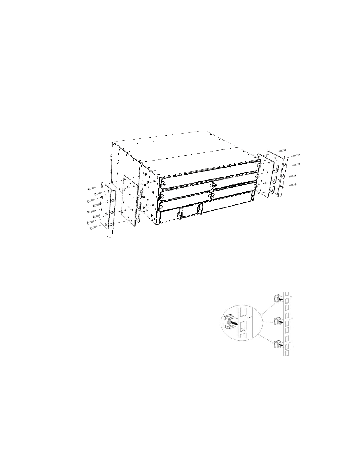
To mount the MPC480 in the rack cabinet, four rack mounting brackets are supplied
with the MPC480; two cable brackets and two angle brackets. There are different ways
to attach the brackets to the chassis. For more details, see “Installation kit” on page 24.
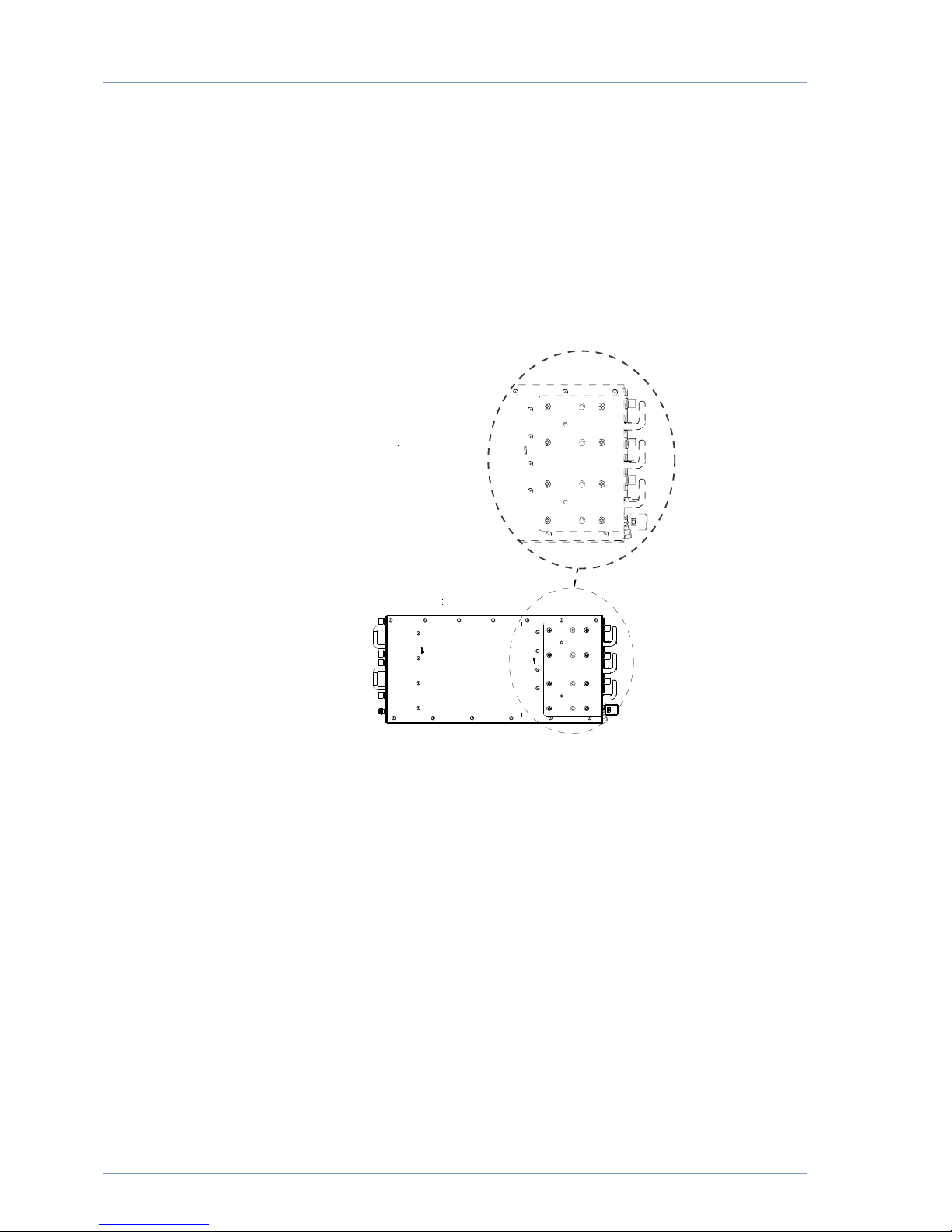
The standard option for attaching the brackets is shown in figure below. Using the
screws provided to attach the brackets to the MPC480 chassis. You will need eight
screws for each side.
Figure 1 Attach rack brackets to MPC 480 chassis
Mount chassis in rack cabinet
On standard rack cabinets, there are markings to indicate the distance for each rack unit
(RU). If possible, use these markings as a reference to correctly position the chassis.
1. Clip the six cage nuts into the rear of a hole in
the rack cabinet (if possible, select a hole with
a reference mark), using three cage nuts on
each side of the cabinet. The distance between
each cage nut is 1 RU.
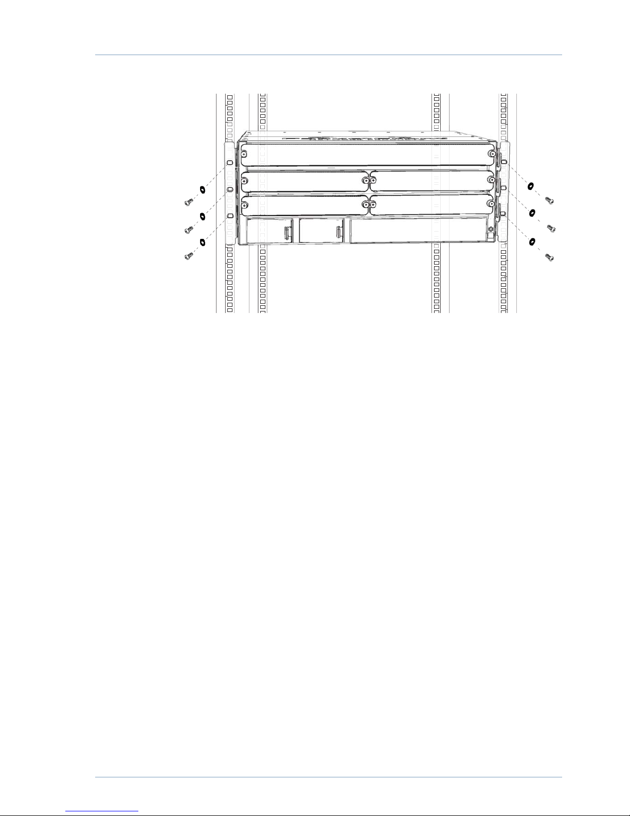
2. Lift the chassis into the rack cabinet and align
the six angle bracket holes with the cage nuts.
Note: While it is possible for a single person to
lift the empty MPC480 chassis, it is recommended that a second person assist in
this procedure. Alternatively, a cabinet shelf can be temporarily mounted to
support the chassis in the rack cabinet and subsequently removed after the chassis
is secured.
3. Using the washers and screws provided, attach the MPC480 to the cabinet rack.
Page 13
Getting started
7
Figure 2 Attach MPC480 to rack cabinet
Page 14
8
Ground chassis to rack
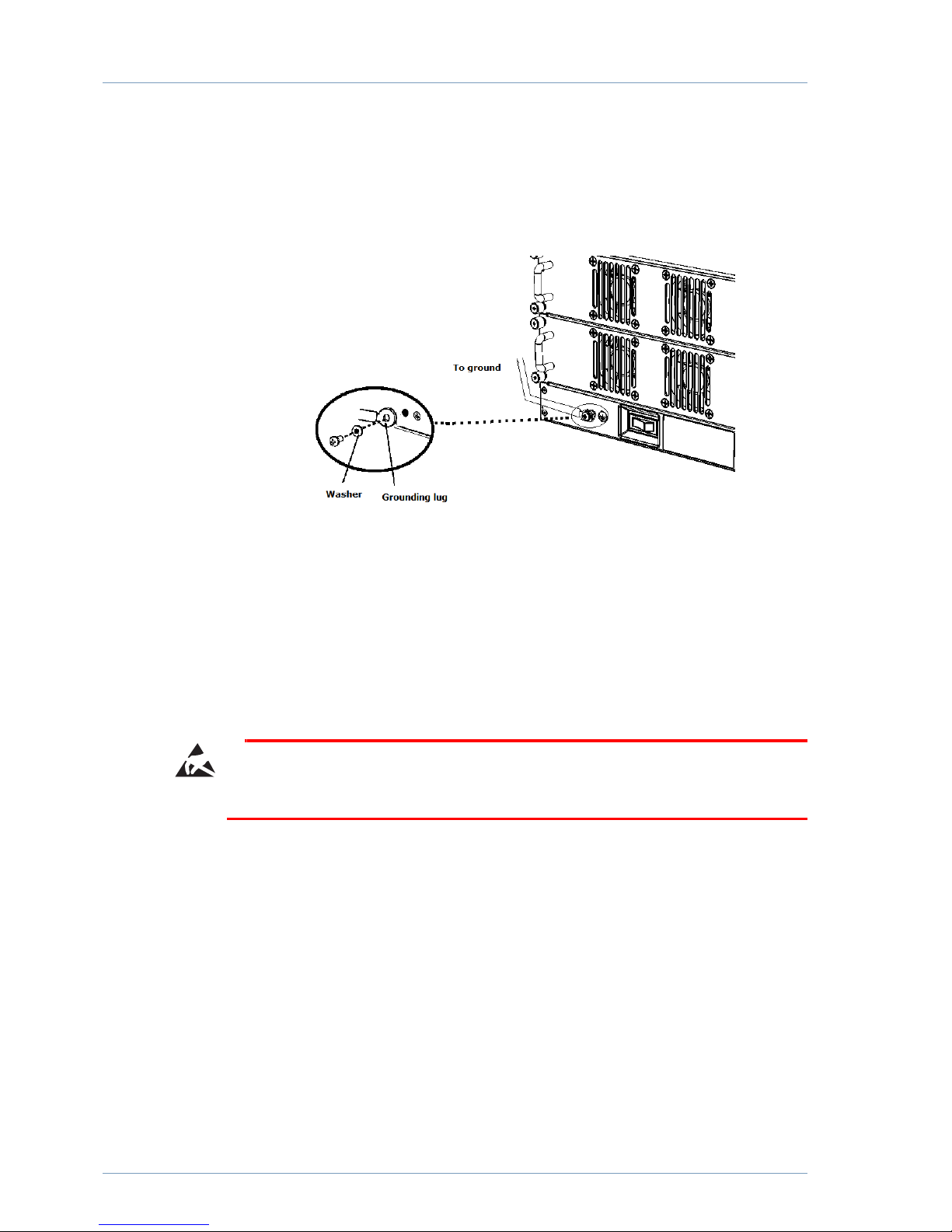
The grounding kit contains the grounding cable and a screw with washer. Locate the
grounding socket at the rear of the chassis and connect the grounding cable lug using
the screw provided.
Figure 3 Connect grounding cable
Connect the other end of the cable to rack or other external GND for the installation
site.
Installing mainboard
The mainboard is designed for simple and foolproof installation and does not require
any tools.
Caution
It is recommended to use a ESD protection wrist strap during installation.
To install the mainboard:
1. Remove the cover plate from the mainboard slot of the MPC480 chassis by releasing
the locking screws on both sides.
2. If available, plug an ESD protection wrist strap into the ESD socket on the front of
the MPC480 before you remove the ESD protection bag from the mainboard.
Page 15
Getting started
9
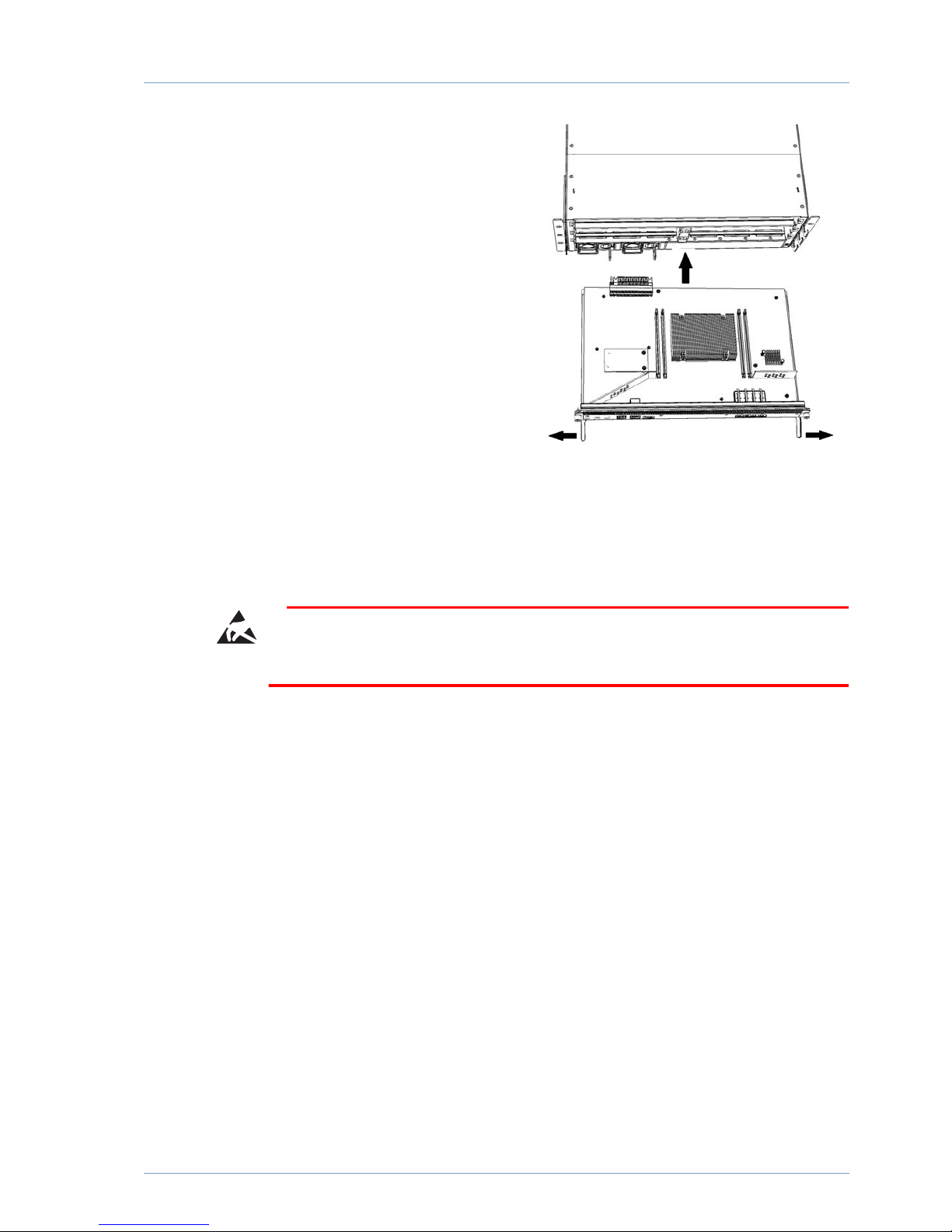
3. Gently open the locking levers on
the mainboard until fully extended
and firmly slide the mainboard into
slot 0 of the MPC480 chassis until
the locking levers snap into place.
4. Tighten the two nuts to secure the
mainboard.
The mainboard is ready to be equipped
with fiber transceivers. See “SFP Prod
ucts” on page 37 on how to install the
appropriate tranceivers.
Installing linecard
The linecard is designed for simple and foolproof installation and does not require any
tools. The linecard is installed in the slots 1 to 4.
Caution
It is recommended to use a ESD prevention wrist strap during installation.
To install the MPC480 linecard:
1. Remove the cover plate from one of the linecard slots by releasing the nuts on both
sides.
2. If available, plug an ESD protection wrist strap into the ESD socket located on the
MPC480 front panel before you remove the ESD protection bag from the linecard.
Page 16
10
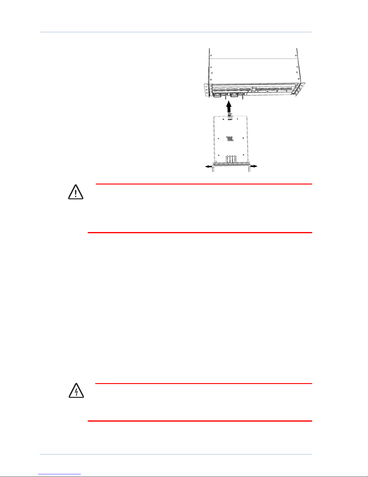
3. Open the locking levers on the
MPC480 linecard and firmly slide the
board into a linecard slot of the
MPC480 chassis until the locking
levers snap into place.
4. Tighten the two nuts to secure the
linecard.
The linecard is ready to be equipped with
fiber transceivers. See “SFP Products” on
page 37 on how to install the appropriate
tranceivers.
Caution
Cover plates for the linecard slots are only to be removed when installing a linecard.
If the linecard slots are not covered, the cooling airflow over the backplane may be
adversely affected and cause a system shutdown.
Installing power supply unit(s)
The MPC480 power supply unit (PSU) is designed for simple and foolproof installa
tion and does not require any tools.
To install the PSU:
1. Remove the cover plate from one of the PSU slots of the MPC480 chassis by
pressing the locking lever outwards and gently pulling the cover plate.
2. Insert the PSU into the MPC480 chassis.
3. Gently slide the board all the way into the chassis until the locking handle snaps into
place.
4. Plug in the power cable provided in the PSU socket.
Warning
Ensure that the power supply cable is not connected to mains power supply when
inserting/removing plug from PSU socket.
Page 17

Getting started
11
Connecting power to the MPC
The MPC runs on 90/264V 5060Hz AC, or 48V DC depending on the power unit
supplied. Installation of the mains power sockets must be performed by a licensed elec
trician.
Turn power on
To power up the MPC:
1. Connect the mains power cable to the MPC power connector.
2. Connect the mains power cable to the power socket.
3. When the mains cable is connected, the MPC480 power button at the rear of the
device can be pressed to position “I”. Depending in which slot the PSU is installed,
the power LED marked PSUA or PSUB will light up.
The MPC480 will now automatically boot and the “System” LED will start to flash.
The MPC480 is now installed and you can connect the appropriate patch cables to the
installed transceivers. To establish connectivity with the network, at least one port must
be connected with a network cable.
Setup the MPC480
The MPC480 mainboard is loaded with a default configuration. You will have to make
some basic configuration settings to enable network connectivity. The following tasks
must be performed before the MPC480 can communicate with the network:
• Log in to the MPC480 operating system
• Set the login password
• Set the IP address on a management interface
• Save your changes
Page 18

12
Log in to the MPC480 operating system
To login to the MPC480 for the first time, connect your PC to the console port on the
mainboard using a suitable cable. See
Using your favorite terminal software, open a window to connect to the MPC480.
You will see a command line prompt for the user name.
username:
By default, there is no authentication configured on the MPC480 so just press the Enter
key to continue.
You will be prompted for a password. Press the Enter key again.
password:
The welcome screen text will be now be displayed indicating the software version run
ning on the MPC480:
Intelligent Broadband Operating System (iBOS), Version 7.0.0-ED-R
Copyright (c) 2015 by Waystream AB
Routing Engine Copyright (c) 2015 IP Infusion Inc.
mpc>
Set the login password
It is recommended that a local user account is created to prevent unauthorised changes
to the MPC480.
To configure a new user account, use the username command.
mpc> enable
mpc# configure terminal
mpc(config)# username <username> password <password> encrypted
The <username> and <password> strings can be any combination of alphanumeric
characters (az, 09) and a maximum eight characters. The encrypted keyword stores
the password as an encrypted entry.
Set IP address on management interface
The mainboard has one management ethernet port (ethernet0) which is normally used
for the initial remote configuration. The four 10Gbit/s ports on the mainboard can also
be used as management interfaces and the ports 1,2,3 and 4 are denoted as tengiga
bitethernet0/1, tengigabitethernet0/2, tengigabitethernet0/3 and tengigabitethernet0/
4 respectively.
To connect with your network, the designated management port needs to have an IP
address configured.
To configure the IP address on the management port, enter the following configuration
commands:
mpc# configure terminal
mpc(config)# interface ethernet0
mpc(config-eth)# ip-address 10.0.0.1/16
mpc(config-eth)# no shutdown
mpc(config-eth)# exit
mpc#
Note: The output differs depending on the ports installed and configuration thereof.
Page 19

Getting started
13
Save your changes
To save your configuration changes, use the write command.
mpc# write mem
Check installed ports
To verify that the installed MPC480 ports are installed and operating correctly, the fol
lowing checks should be performed:
Check interfaces
To view a summary of all installed interfaces, use the show interface brief command.
mpc> show interface brief
Interface Admin Link Oper Lastchange
-------------------------------------------------------------------------------downstream0 Up Up Yes 1h
ethernet0 Up Up Yes 1h
tengigabitethernet0/1 Up Down No 1h
tengigabitethernet0/2 Up Down No 1h
tengigabitethernet0/3 Down Down No 1h
tengigabitethernet0/4 Up Down No 1h
tengigabitethernet1/1 Down Down No 1h
tengigabitethernet1/2 Down Down No 1h
tengigabitethernet1/3 Down Down No 1h
tengigabitethernet1/4 Down Down No 1h
tengigabitethernet2/1 Down Down No 1h
tengigabitethernet2/2 Down Down No 1h
tengigabitethernet2/3 Down Down No 1h
tengigabitethernet2/4 Down Down No 1h
tengigabitethernet4/1 Up Down No 1h
tengigabitethernet4/2 Up Down No 1h
tengigabitethernet4/3 Up Down No 1h
tengigabitethernet4/4 Up Down No 1h
mpc>
To view the detailed configuration of a specific interface, use the show interface <inter
face>
command:
mpc> show interface tengigabitethernet0/1
tengigabitethernet0/1 is administratively up, line protocol is down (1h ago)
Duplex auto (n/a), Speed auto (n/a)
Hardware address 0008.ae8f.0400
Interface availability is 0.0%
Created 1D4h ago, 0s of accumulated uptime
IP MTU 1500 bytes, Ethernet MTU 1538 bytes
Inet6 address fe80:3::208:aeff:fe8f:400/64
10 seconds input rate 0 bits/sec, 0 packets/sec
10 seconds output rate 0 bits/sec, 0 packets/sec
0 packets input, 0 bytes, 0 input errors
0 input queue drops, 0 unknown protocols
0 broadcasts, 0 multicasts, 0 pause
0 runts, 0 oversized, 0 CRC
0 jabbers, 0 fragments, 0 symbol, 0 alignment
0 packets output, 0 bytes, 0 output errors
0 output queue drops
0 broadcasts, 0 multicasts, 0 pause
0 collisions, 0 deferred
Page 20

14
To view the current routing information for connected interfaces, use the show ip route
command:
mpc> show ip route
Codes: K - kernel, C - connected, S - static, CL - client, B - BGP
O - OSPF, IA - OSPF inter area
N1 - OSPF NSSA external type 1, N2 - OSPF NSSA external type 2
E1 - OSPF external type 1, E2 - OSPF external type 2
* - candidate default
Gateway of last resort is 10.0.0.254 to network 0.0.0.0
Codes Destination
-------------------------------------------------------------------------------S* 0.0.0.0/0 [1/0] via 10.0.0.254, ethernet0, 1d04h36m
C 10.0.0.0/24 is directly connected, ethernet0, 1d04h36m
C 10.22.6.1/32 is directly connected, loopback1, 1d04h36m
C 10.22.6.4/32 is directly connected, loopback2, 1d04h36m
mpc>
Page 21
15
Configuring the MPC480
The MPC480 mainboard has a console port that is used to set configuration
information when the MPC480 is upandrunning. During the boot process, the
MPC480 outputs information about the boot progress, and if any problems are
encountered.
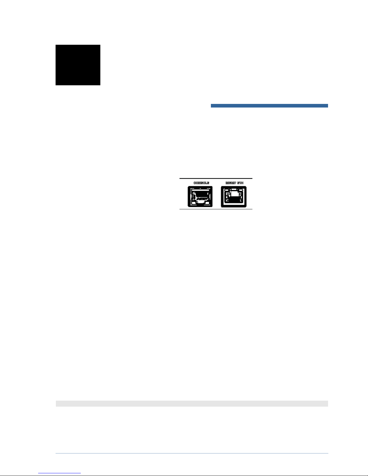
Figure 4 Management interfaces on mainboard
To connect to the console port, you typically need a RS232 to 9 pin DSub cable to
the serial port connector on your terminal.
Connecting to the console interface port
Connect your terminal to the console port using the appropriate cable.
Configure your terminal software using the following settings:
• 8 data bits, no parity and 1 stop bit (8N1)
• No flowcontrol or hardware flowcontrol (RTS/CTS)
• 115200 bps baudrate rate
The bootloader process
When the power is first turned on, the MPC480 immediately starts the bootloader
software. You can follow this boot process on the console.
The bootloader locates a bootable image stored either on a USB drive or from the on
board memory. The image is decompressed when read into memory. The bootloader
displays the following message when it is decompressing the iBOS image:
Decompressing ibos-mpc480se-7.0.0-ED-R.bz2 (press any key to abort)
The local filename of the image being decompressed is displayed, e.g. the image file
name is ibosmpc480se7.0.0EDR.bz2.
When the iBOS image has been loaded into RAM, the Bootloader will start the main
software. The following message is displayed:
Page 22

16
Running ELF executable at address: 0x80200000
Note:
Pressing any key aborts the boot process and enters the Bootloader command line
interface. To restart the Bootloader, enter the command boot.
Connect network interfaces
The procedure to connect the network interfaces on the MPC480 is as follows:
1. Identify the port to be configured.
2. Determine the type of SFP to be used, and what model of patch cable to use
3. Insert the SFP module into the MPC480 SFP port
4. Connect the fiber cable to the SFP, and then to the network fiber patch panel or fiber
connector
If the MPC480 has received configuration and there are neighbouring devices connect
ed on the link, the MPC 480 will indicate that link is present on the interface and it is
possible to see link status indicated by the LEDs above the SFP port.
Troubleshooting iBOS
iBOS is a complex software with many configurable features. Some useful commands
to perform basic troubleshooting are described in this manual. For more details on
configuration, see the iBOS 7 Configuration Guide.
The command line interface displays the MPC480 hostname as the prompt.
Check system software
To display the system information, use the show version command. The information
displayed includes the version of iBOS running in the system, the system hostname and
uptime, the model and characteristics of the MPC, its serial number, and other infor
mation.
Example 1 show version
mpc> show version
Intelligent Broadband Operating System (iBOS), Version 7.0.0-ED-R
Copyright (c) 2015 by Waystream AB
Routing Engine Copyright (c) 2015 IP Infusion Inc.
Compiled Fri Feb 4 14:23:07 CEST 2015 by builder Source ID:
1b6b1a17fc5b734f5a2e363be337c2bb6e1ba136
MPC uptime is 0 minutes
Last boot: warm start
System image file is "ibos-MPC-7.0.0-R.bz2", version ibos-MPC-7.0.0-ED-R
System: MPC, 8 10/100/1000BaseTX ports
Central Office Bootloader version: boot-MPC-4.0.0-R
Supported IPD1248 firmware version: 6.5.*
Suggested IPD1248 firmware image: VE_6_5_17_IP_2_4_1_tco.bin
Board revision: 0
Product ID: FLF501NC
Serial number/Base MAC address: 00900B10D2C0
Page 23

Configuring the MPC480
17
Processor: CN5860-1 (mipseb)
262144K bytes CPU RAM
mpc>
Check installed ports
To verify that the installed MPC480 ports are installed and operating correctly, the fol
lowing checks should be performed:
Check interfaces
To view a summary of all installed interfaces, use the show interface brief command.
mpc> show interface brief
Interface Admin Link Oper Lastchange
-------------------------------------------------------------------------------downstream0 Up Up Yes 1h
ethernet0 Up Up Yes 1h
tengigabitethernet0/1 Up Down No 1h
tengigabitethernet0/2 Up Down No 1h
tengigabitethernet0/3 Down Down No 1h
tengigabitethernet0/4 Up Down No 1h
tengigabitethernet1/1 Down Down No 1h
tengigabitethernet1/2 Down Down No 1h
tengigabitethernet1/3 Down Down No 1h
tengigabitethernet1/4 Down Down No 1h
tengigabitethernet2/1 Down Down No 1h
tengigabitethernet2/2 Down Down No 1h
tengigabitethernet2/3 Down Down No 1h
tengigabitethernet2/4 Down Down No 1h
tengigabitethernet4/1 Up Down No 1h
tengigabitethernet4/2 Up Down No 1h
tengigabitethernet4/3 Up Down No 1h
tengigabitethernet4/4 Up Down No 1h
mpc>
To view the detailed configuration of a specific interface, use the show interface <inter
face>
command:
mpc> show interface tengigabitethernet0/1
tengigabitethernet0/1 is administratively up, line protocol is down (1h ago)
Duplex auto (n/a), Speed auto (n/a)
Hardware address 0008.ae8f.0400
Interface availability is 0.0%
Created 1D4h ago, 0s of accumulated uptime
IP MTU 1500 bytes, Ethernet MTU 1538 bytes
Inet6 address fe80:3::208:aeff:fe8f:400/64
10 seconds input rate 0 bits/sec, 0 packets/sec
10 seconds output rate 0 bits/sec, 0 packets/sec
0 packets input, 0 bytes, 0 input errors
0 input queue drops, 0 unknown protocols
0 broadcasts, 0 multicasts, 0 pause
0 runts, 0 oversized, 0 CRC
0 jabbers, 0 fragments, 0 symbol, 0 alignment
0 packets output, 0 bytes, 0 output errors
0 output queue drops
0 broadcasts, 0 multicasts, 0 pause
0 collisions, 0 deferred
To view the current routing information for connected interfaces, use the show ip route
command:
mpc> show ip route
Codes: K - kernel, C - connected, S - static, CL - client, B - BGP
Page 24

18
O - OSPF, IA - OSPF inter area
N1 - OSPF NSSA external type 1, N2 - OSPF NSSA external type 2
E1 - OSPF external type 1, E2 - OSPF external type 2
* - candidate default
Gateway of last resort is 10.0.0.254 to network 0.0.0.0
Codes Destination
-------------------------------------------------------------------------------S* 0.0.0.0/0 [1/0] via 10.0.0.254, ethernet0, 1d04h36m
C 10.0.0.0/24 is directly connected, ethernet0, 1d04h36m
C 10.22.6.1/32 is directly connected, loopback1, 1d04h36m
C 10.22.6.4/32 is directly connected, loopback2, 1d04h36m
mpc>
Page 25
19
MPC480 Overview
This chapter provides an overview of the MPC480 product for installation purposes
only.
The MPC480 edge router chassis is designed for installing in a standard 19” rack, for
example in a data center or central office (CO) environment.
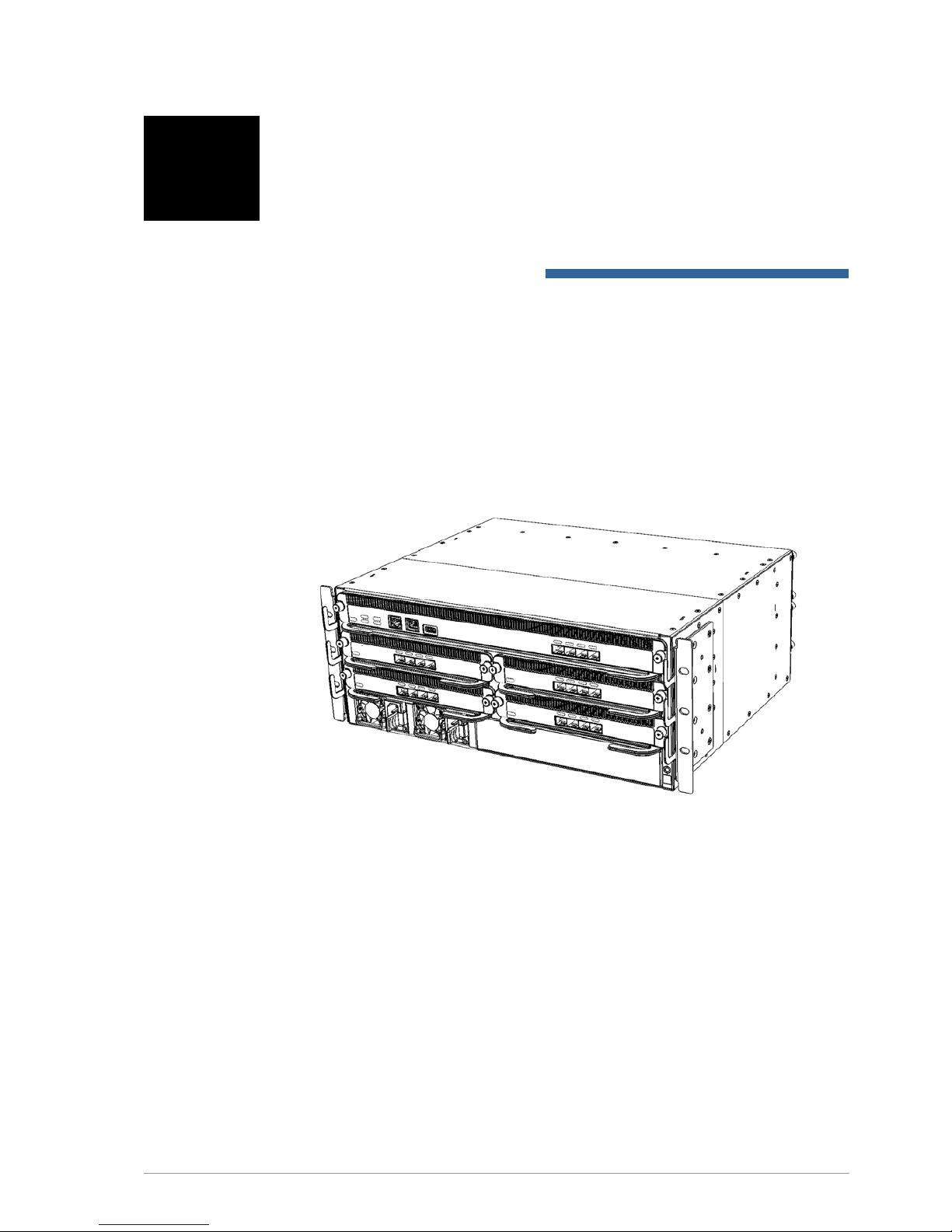
Figure 5 MPC480 Edge Router
For a complete specification of the MPC480 products, see “MPC480 Technical Spec
ification” on page 35.
Restricted access location
The MPC480 is designed to be mounted in a 19inch rack in a restricted access loca
tion. For restricted access locations, the following applies:
• access can only be gained by SERVICE PERSONS or by USERS who have been
instructed about the reasons for the restrictions applied to the location and about
any precautions that shall be taken
• access is through the use of a TOOL or lock and key, or other means of security,
and controlled by the authority responsible for the location
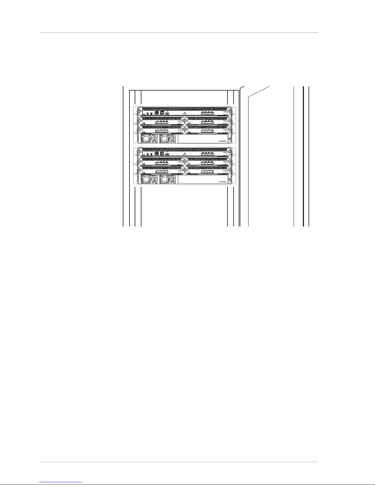
The MPC480 cooling fans are located at the back of the of the unit so ventilation must
be available through the front of the cabinet to allow free airflow so that the MPC can
Page 26
20
maintain a persistent and satisfactory ambient temperature.
Figure 6 MPC rack installation
For rack mounting, the following considerations must be taken:
• Elevated Operating Ambient Temperature When installed in a closed or multi
unit rack assembly, the operating ambient temperature of the rack environment may
be greater than the room ambient. Therefore, consideration should be given to
installing the equipment in an rack environment compatible with the maximum
ambient temperature, see the “MPC480 Technical Specification”
on page 35
.
• Reduced Air Flow Installation of the equipment in a rack should be such that the
amount of air flow required for safe operation of the equipment is not
compromised.
• Mechanical Loading Mounting of the equipment in the rack should be such that
a hazardous condition is not achieved due to uneven mechanical loading.
• Circuit Overloading Consideration should be given to the connection of the
equipment to the supply circuit and the effect that overloading of the circuits might
have on overcurrent protection and supply wiring. Appropriate consideration of
equipment nameplate ratings should be used when addressing this concern.
• Reliable Earthing Reliable earthing of rackmounted equipment should be
maintained. Particular attention should be given to supply connections other than
direct connections to the branch circuit (e.g. use of power strips).
Ventilation of MPC480
The MPC480 is cooled by two internal fan trays. Ensure that air can flow freely from
the front and back of the cabinet.
Page 27
MPC480 Overview
21
MPC480 components
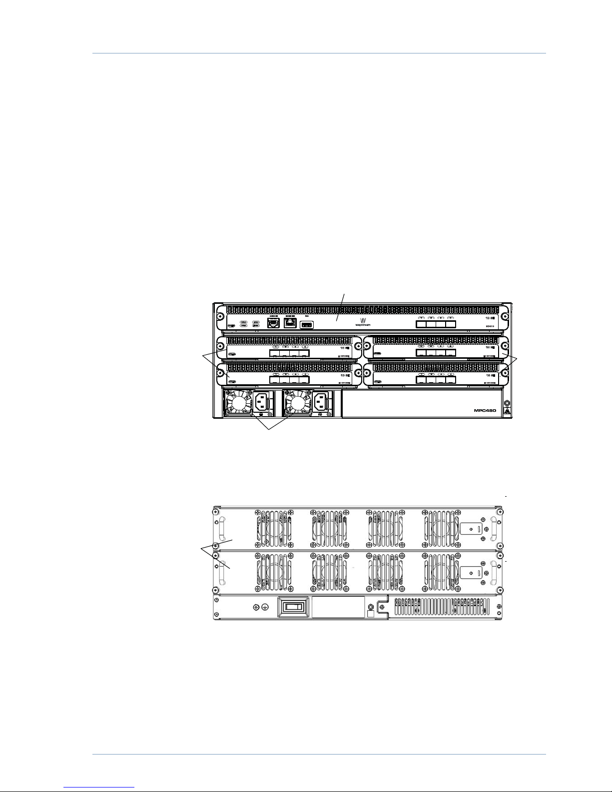
The MPC480 edge router is a 4U rack device which includes the following compo
nents:
• one MPC480 chassis with two preinstalled fan trays (required)
• one mainboard (required)
• up to four linecards (optional)
• primary AC or DC power supply unit (required)
• redundant AC or DC power supply unit (optional, must be same type as primary
PSU)
Figure 7 MPC480 components
Figure 8 MPC480 components rear view
MPC chassis
The following contents are included in the MPC480 Edge Router chassis package:
Mainboard
Linecard
Linecard
PSU
Fantr ay
Page 28
22
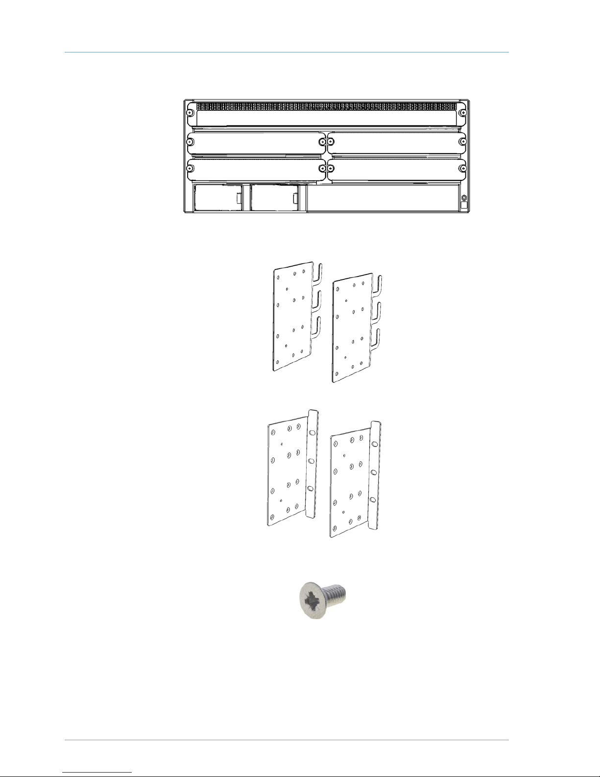
• one (1) MPC480 Edge Router chassis with slot cover plates
• one (1) installation kit including:
– two (2) pcs cable brackets
—two (2) pcs angle brackets
– 16 pcs Phillips screws (M4xL8) for attaching the brackets to the MPC480 (8 per
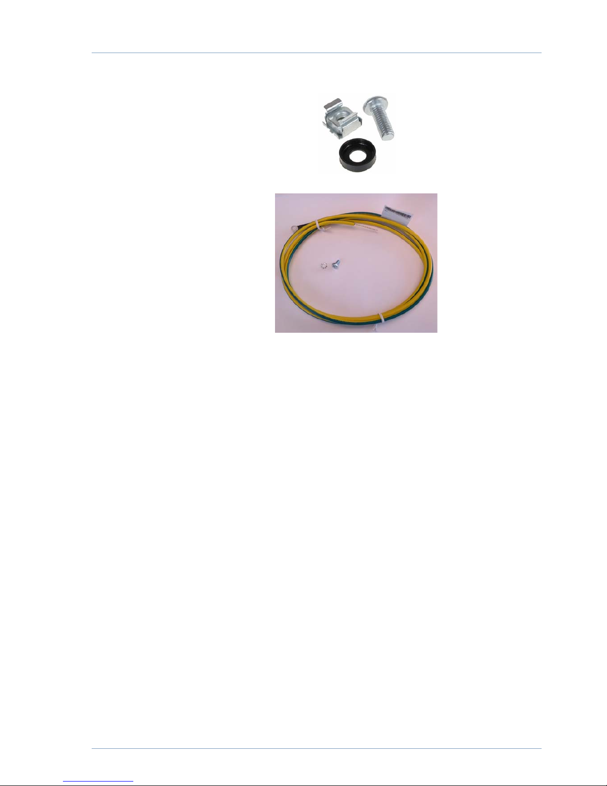
bracket)
– six (6) pcs round 10 mm screws (M4xL8), washers and cage nuts for fixing the
Page 29
MPC480 Overview
23
angle brackets to the rack cabinet
—one (1) earth grounding cable with lock washer and M4L8 screw with tooth washer
Page 30
24
Installation kit
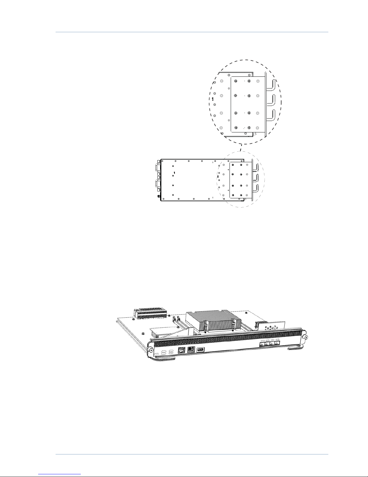
The installation kit includes two types of brackets supplied with the MPC480; cable
brackets and angle brackets;
• cable brackets are used for organizing the cables attached to the front panel
connectors. These are brackets are optional.
• angle brackets are required for mounting the MPC480 to the rack cabinet.
There are two position options for the brackets:
—aligned with front panel
Page 31
MPC480 Overview
25
—recessed to allow a one inch gap to the front of the rack
Note: The cable brackets are optional and may be excluded.
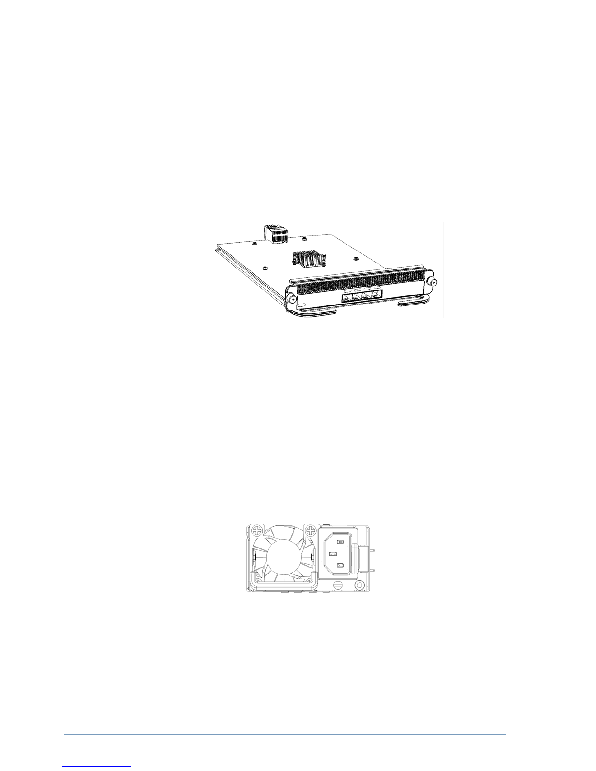
MPC mainboard
The MPC480 mainboard contains the system’s forwarding and control plane and runs
the system firmware. The mainboard is required for the MPC480 to operate. If re
moved, the system will halt until a mainboard is inserted.
Figure 9 MPC480 mainboard
For details on the different mainboards, see “MPC480 Technical Specification” on
page 35.
The physical interfaces for the different mainboards are identical and include:
• one RS232 serial console port
• one remote management port
• one USB port
Page 32
26
• four 10GE (SFP+) ports
MPC480 linecard
Linecards provide extra interface options and features and are used to connect the
MPC480 to other systems in the network. There are four linecard slots numbered
from14. Linecards are optional and can be inserted or removed while the system is
running.
Figure 10 MPC480 linecard
For details on the different linecard models, see “MPC480 Technical Specification” on
page 35.
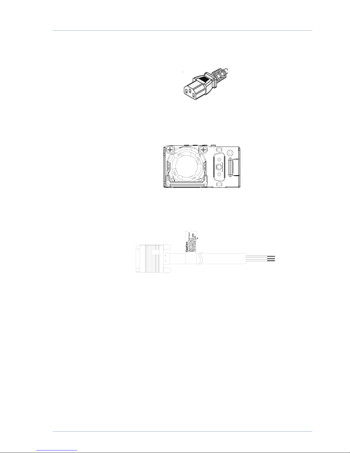
MPC480 PSU
The MPC480 has two slots for hotswappable power modules.
The available PSU models are:
• 100250 VAC, 800 W supplied with EU mains cable
Figure 11 MPC480 AC PSU
A cable with a standard IEC C13 line connector and mains plug (EU) is also supplied.
Page 33
MPC480 Overview
27
Figure 12 AC power cable connector
• 48 VDC, 800W supplied with 800W DC cable
Figure 13 MPC480 DC PSU
A cable with a Positronic 3pin line connector is supplied.
Figure 14 DC power cable connector
The cable is ready to be connected to a grounded DC power supply.
For details on the different PSU models, see “MPC480 Technical Specification” on
page 35.
Page 34
28
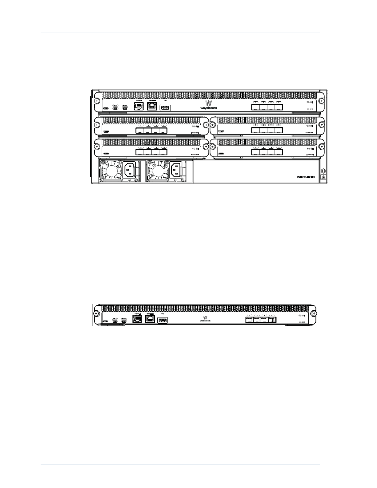
MPC480 Front Panels
For easy access, all MPC480 interfaces are positioned on the front of the chassis.
Figure 15 MPC480 front panel
Mainboard front panel
As the management interfaces for the MPC480 mainboards are identical, the Servi
ceEngine mainboard (MPCSE4818) is used in this manual.
The MPC480 mainboard front panel has the following interfaces:
• one RS232 console port
• one GigabitEthernet management port
• one interface for USB devices
• five mainboard LEDs
Figure 16
MPC480 mainboard front panel
Mainboard LED
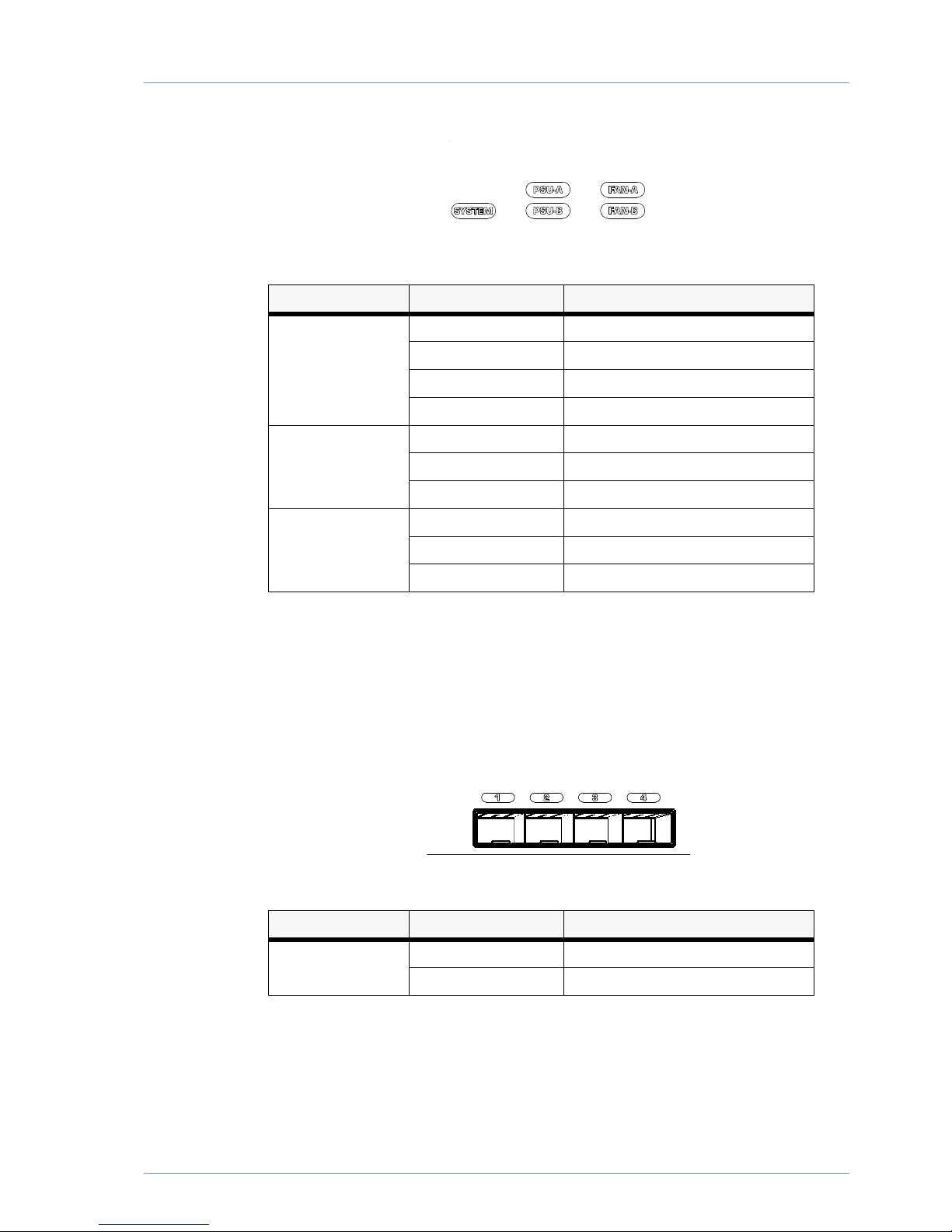
The mainboard has five LEDs that show the mainboard status; System, PSUA and
PSUB,FanA and FanB. See Table 1 for more information.
Page 35
MPC480 Overview
29
Figure 17 Mainboard system LEDs
Table 1 Mainboard LED states
Note: FLASHING interval is approximately 500 ms.
Mainboard ports
There are four ports for 10 GE SFP+ optical transceiver modules. Each port has a num
bered LED that indicates if the link status of the port.
Figure 18 Mainboard ports
Table 2 Mainboard port LED states
LED STATE DESCRIPTION
SYSTEM GREEN MAINBOARD RUNNING
GREEN FLASHING BOOTING FIRMWARE
RED SYSTEM ERROR
OFF MAINBOARD NOT STARTED
PSUA / PSUB GREEN POWER ON
RED PSU FAILURE
OFF NO POWER
FANA / FANB GREEN FAN RUNNING
RED FAN ERROR
OFF MAINBOARD NOT STARTED
LED STATE DESCRIPTION
1 thru 4 ON LINK UP
OFF LINK DOWN
Page 36
30
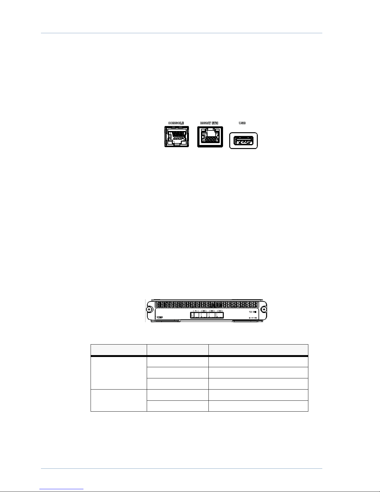
Console and Ethernet management ports
The MPC has one serial console port for management of the unit, able to operate in
9600 to 115200 bps. The connector type is RS232. Default speed is 115200 bps, but
this can be changed using the Bootloader or iBOS software. See the "MPC Bootloader
User Guide" and/or the configuration register settings section of the "iBOS Command
Reference Guide".
Figure 19 Console port and Ethernet management ports
For the console port, a RJ45 console cable is connected to the serial port connector on
your terminal.
Configure your terminal software to 115200 bps, 8 data bits, no parity and 1 stop bit
(8N1). No flowcontrol or hardware flowcontrol (RTS/CTS) should be used.
The Ethernet management port uses a Cat5 or higher Ethernet cable to connect to the
network and allows remote management of the MPC480.
Linecard front panel
The following linecards are available:
Except for the physical ports, the front panel design for MPC480 linecards is identical.
and the MPC4X10GEETH is used in this manual.
The linecard front panel has four slots for SFP+ ports. In addition, there are also system
and port LED indicators.
Figure 20
MPC480 4x10GE linecard front panel
Table 3 Linecard system LED states
MPC480 power connectors
The power socket is located on the front of the MPC480 PSU.
LED STATE DESCRIPTION
SYSTEM GREEN LINECARD RUNNING
RED LINECARD ERROR
OFF LINECARD NOT STARTING
Port LEDs 1 thru 4 OFF LINK DOWN
ON LINK UP
Page 37
MPC480 Overview
31
MPC480 rear panel
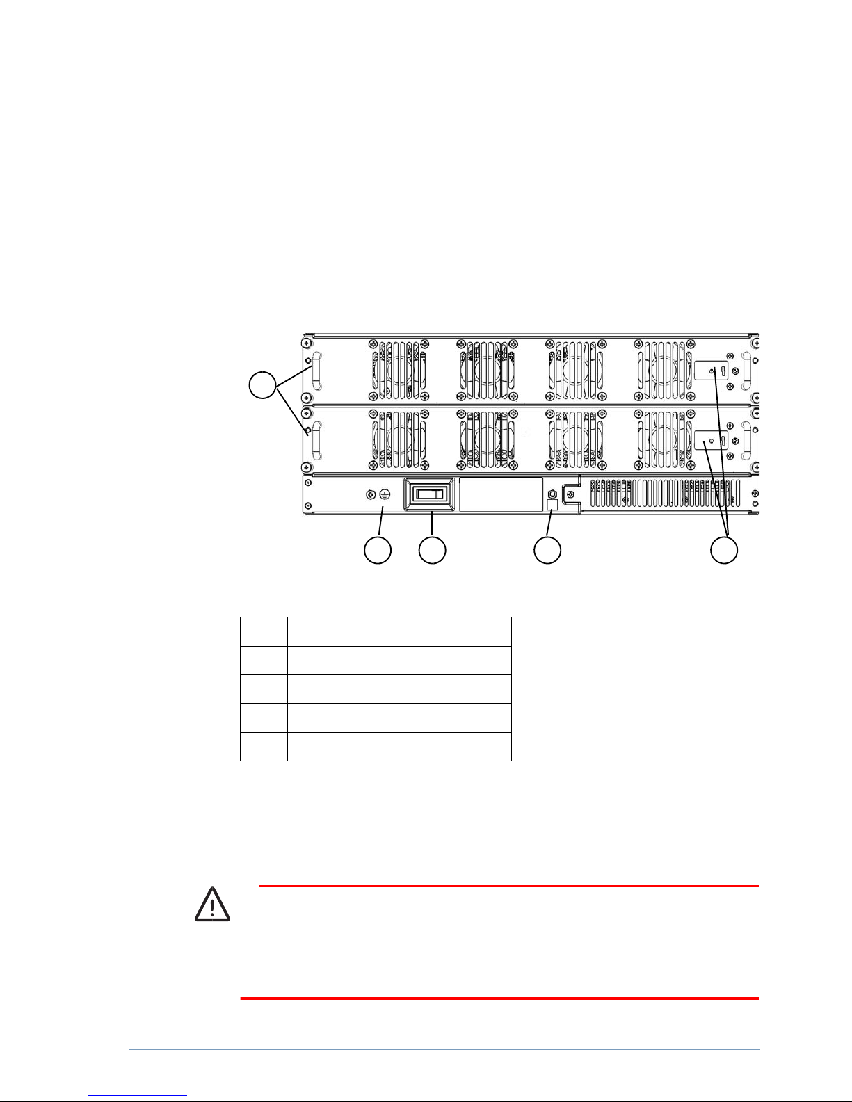
The rear of the MPC480 includes:
• cooling fan trays with LEDs
• power button
• grounding socket
Figure 21 Backplane of MPC
Fan trays
There are two cooling fan tray units preinstalled that can be individually replaced. The
unit does not need to be powered off when the fans unit is being replaced.
Caution
The MPC480 may overheat and shutdown if it is operating without proper cooling
for more than 120 seconds. Ensure that the replacement fan can be installed
immediately when you are hot swapping a fan tray.
1 Fan tray
2 GND socket
3 ON/OFF button
4 ESD protection socket
5 Fan tray LED
1
2 3 4 5
Page 38
32
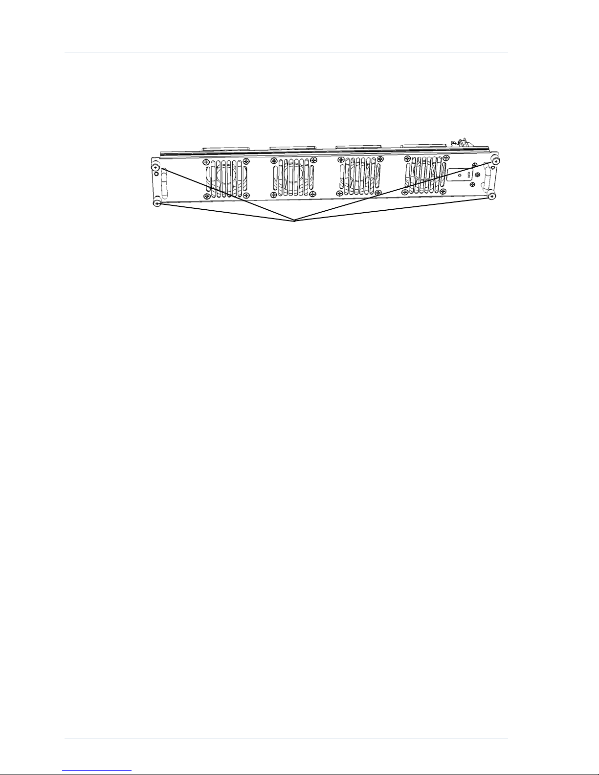
Figure 22 Fan tray
There are four locking screws fitted to the fan tray that lock the unit in position.
To replace a fan tray, do the following:
1. Unscrew the locking nuts and gripping the two handles gently pull the fan tray out
of the chassis.
2. Align the replacement fan tray alignment pins in the corresponding holes on the
chassis and push the fan tray into the slot. The green fan tray LED lights up and the
fans start.
3. Insert and tighten the restraining screws.
Locking screws
Page 39
MPC480 Overview
33
Power button
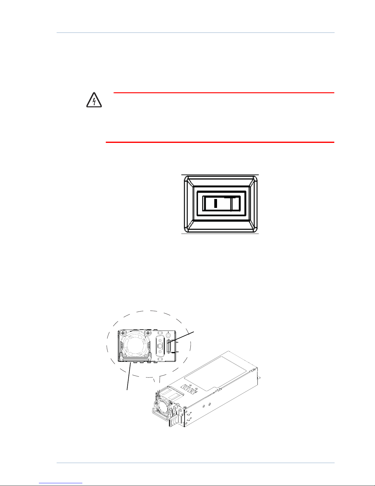
There is a main power button located on the rear of the MPC480. The button turns
on mains power to both PSUs simultaneously.
Warning
This button cuts mains power to the backplane. The PSU will still be connected to
mains power and there may still be some residual charge in some components.
To completely isolate the MPC480, all power cables must be disconnected.
Figure 23 Power button
Power modules
There are slots for two power supply modules. The modules can be replaced while the
unit is still running, socalled “hotswapping”.
Figure 24 MPC480 PSU
To remove the power module,
Handle
Lock lever
Page 40

34
1. Remove the power cable
2. Lift the handle.
3. Firmly grip the module handle while pressing the locking lever and pull the PSU out
from the chassis slot
The new PSU can then be inserted. Remember to push the handle down before con
necting the mains power.
Page 41

35
Appendix A – MPC480 Technical
Specification
This appendix contains relevant technical specifications for MPC480 products covered
in this installation guide.
Physical
Mainboard
The physical specifications for MPC480 mainboards are as follows:
Linecard
The physical specifications for MPC480 linecards are as follows:
Mainboard model MTBF Power Weight Interfaces
MB 4816 578,193 hours Normal: 84.7W
Full: 99.22W
2.95 kg Mainboard with 1.6 GHz CPU incl:
1 console port
1 RJ45 GE outofband management port
4 x 10GE SFP+
1 USB 2.0 port (DISABLED)
MB 4818 578,193 hours Normal: 84.7W
Full: 99.22W
2.95 kg Mainboard with 1.8 Ghz CPU incl:
1 console port
1 RJ45 GE outofband management port
4 x 10GE SFP+
1 USB 2.0 port (DISABLED)
Linecard model MTBF Power Weight Interfaces
LC4X10GE 4,484,291 hours 10.23W 1.0 kg 4 x 10GE SFP+
LC40X1GE 4,484,291 hours 10.23W 1.0 kg 20 x 1GE SFP linecard
40 x 1GE CFSP linecard
MPC4801X40GE 4,484,291 hours 10.23W 1.0 kg 1 x 40GE QSFP+ linecard
Page 42

36
Technical data
Physical dimensions
H*W*D (mm) 170 * 440 * 360
Weight 14.9 kg (empty chassis with fan trays)
21.45 kg (fully equipped)
Standard 19inch rack units 4
Power and Safety
MPC480AC800 100 – 240 VAC 50 – 60 Hz, 800W
MPC480DC800 48 VDC, 800W
Weight: 0.8 kg
Power consumption Normal load: 102.8W
Full load: 221.8W
Standards compliant CE, FCC, ETL
Environmental
Storage temperature 10° to 70° C
Operating humidity 10% to 90%, noncondensing
Heat dissipation max 46 watts
Operating temperature 0° to 45° C
Airflow Min: 123 CFM
Max: 402 CFM
Page 43
37
Appendix B – SFP Products
Overview
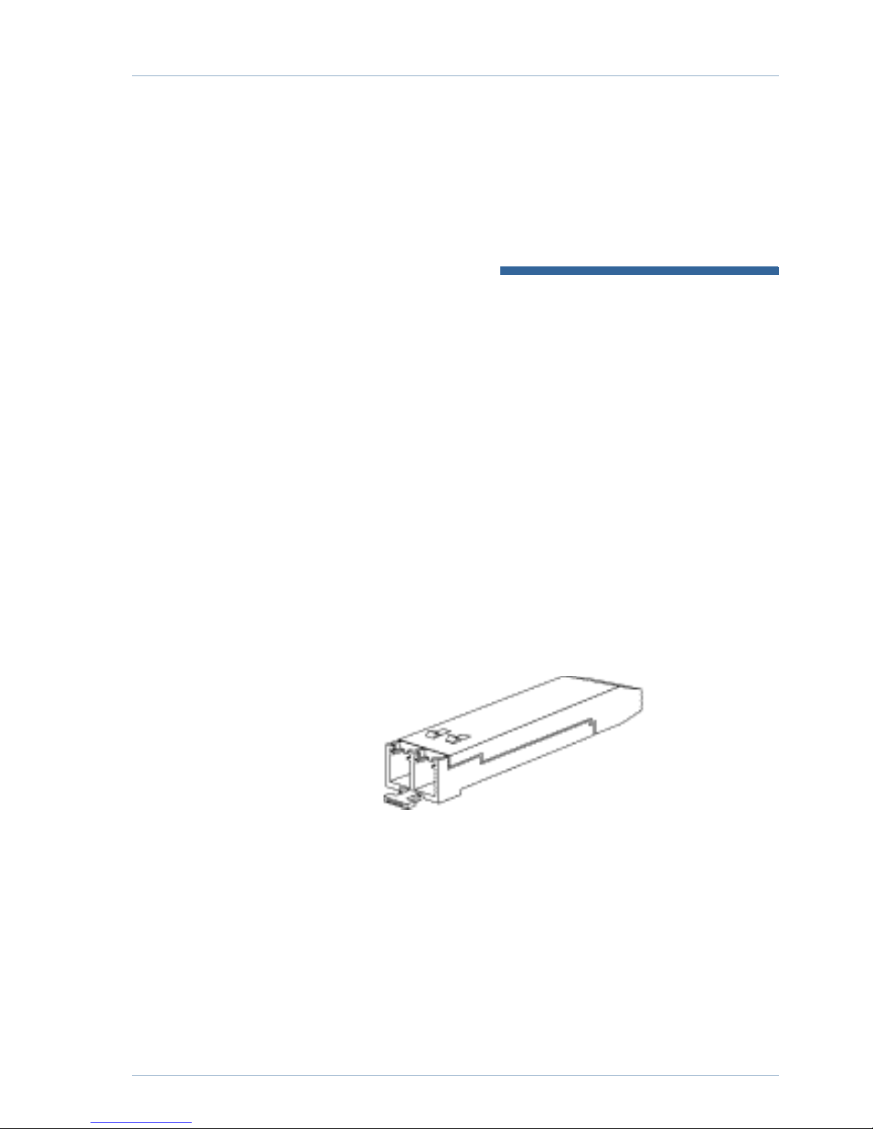
The SFP (1GE) and SFP+ (10GE) interfaces are a series of optical transciever modules
that enable the hardware to be fitted with suitable network interfaces for different
needs.
By using standardized safety requirements, Waystream SFPs are certified together with
the Waystream hardware. Waystream hardware is aware of the certified SFPs and will
issue a warning when noncertified SFPs are connected.
This manual does not describe the product specifications for the Waystream SFP
modules. Models and data for Waystream SFPs can be found in separate data sheets.
SFPs named in this document are used for examples only, and do not constitute a
preference.
Figure 1 SFP optical tranceiver
Note: Detailed information about installed SFPs is shown by running the show
interface sfp
command from the iBOS prompt.
When a Waystream SFP is inserted in the router, the router software reads the EE
PROM to check the serial number, vendor name and ID, and recomputes the security
code and CRC. If the serial number, vendor name or ID, security code, or CRC is in
valid, the switch places the interface in an errordisabled state.
The SFP also provides link status information and other valuble statistics to determine
the operation and quality of the connection to the adjacent device. This information is
available through the iBOS CLI.
Note: If you are using a nonWaystream approved SFP module, Waystream extends
Page 44

MPC480 Installation Guide
38
no warranty for the operation of the device with this interface. The following
warning message will be generated by iBOS during startup:
Non-Waystream SFP
Any damage incurred on this unit due to the use of
non-Waystream SFP is not covered by warranty.
Vendor: WTD
Part number: RTXM228-551
Serial number: 500008990041
Date code: 110903
Page 45
39
Safety
Before installing an SFP module or attempting to handle a Waystream broadband rout
er equipped with SFP slots, you should read and understand the safety information in
this document. Laser warnings only apply to fiberoptic SFP modules.
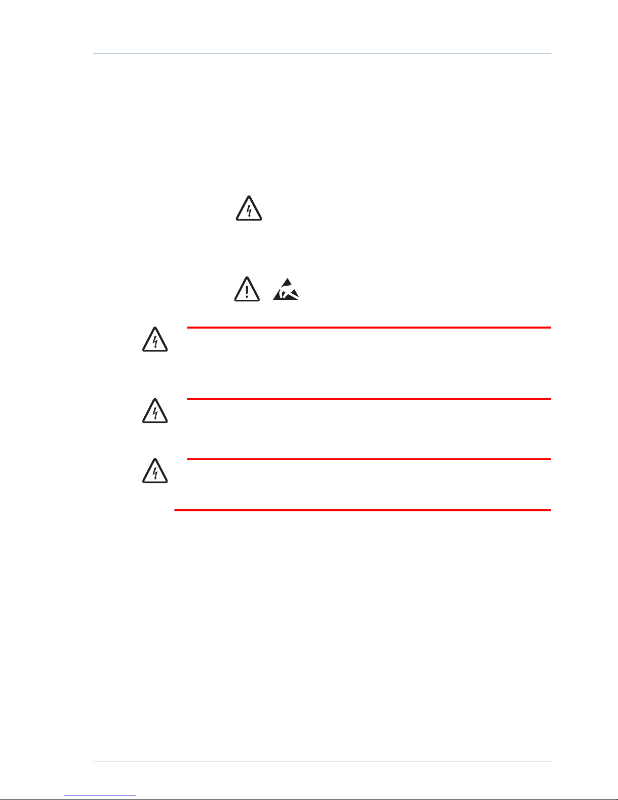
Figure 2 Warning symbol
Figure 3 Caution symbols
Warning
Class 1 laser product. Do not position your eye directly infront of the SFP if the dust
plugs are not installed!
Warning
Laser beam is exposed when dust plug is removed and fiber not installed.
Warning
Only trained staff should install or replace SFPs.
Page 46

MPC480 Installation Guide
40
Caution
SFPs are electronic devices and sensitive to static electricity. Always use an ESD
preventive wrist strap when handling an SFP. ESD damages can cause performance
and lifetime degradation.
Caution
Protect your fiberoptic components, like SFPs and cables, by inserting clean dust
plugs when not connected to other equipment. Clean the optic components
whenever you intend to connect them. Avoid getting dust and other contaminants
into the optical receptacles, as fibre optics do not work correctly when obstructed
with dust.
Caution
When using shorter distances of singlemode fiber cable, you may need to insert an
inline optical attenuator in the link to avoid overloading the receiver. When the
fiberoptic cable is less than 20 km and the link budget is more than 15dB, insert a
5 to 10 dB optical attenuator between the fiberoptic cable plant and the receiving
port of the SFP.
Caution
Under no circumstances should the SFP insertion or removal require physical force.
handling. Always be gentle and use only your thumb and index finger!
Page 47

41
Insertion and removal
Inserting an SFP module
1. Attach an ESDpreventive wrist strap to your wrist and to a bare metal surface on
the chassis or the common ground connector at the back of the module.
2. Find the send (TX) and receive (RX) markings that identify the top side of the SFP
module.
3. Align the SFP module in front of the SFP slot opening with top side facing upwards.
4. Carefully insert the SFP module into the slot until you feel the connector on the
module snap into place.
5. Remove the dust plugs from the cable and the SFP. Clean the connectors and the
SFP with dedicated fibre cleaning tools and carefully insert the cable(s) until they
snap into place.
6. The SFP is now ready. The operating status is shown by the port LEDs.
Note: Do not remove the dust plugs from the fiberoptic SFP module port or the
rubber caps from the fiberoptic cable until you are ready to connect the cable.
The plugs and caps protect the SFP module ports and cables from
contamination and ambient light.
Removing an SFP module
1. Attach an ESDpreventive wrist strap to your wrist and to a bare metal surface on
the chassis or the common ground connector at the back of the module.
2. Disconnect the cable from the SFP module and reinstall the dust plugs.
3. Depending on the type of SFP there are different locking mechanisms:
A baleclasp latch that should be gently pulled outanddown until the SFP releases.
A small button that should be gently pressed until the SFP releases.
4. Place the removed SFP module in an antistatic bag or other protective environment.
Page 48

MPC480 Installation Guide
42
Page 49

MPC480 Installation Guide
1
Index
B
boot process . . . . . . . . . . . . . . . . . . . . . . . . . . 15
boot progress. . . . . . . . . . . . . . . . . . . . . . . . . . 15
boot progress, display information . . . . . . 15
bootloader software. . . . . . . . . . . . . . . . . . . . 15
C
Check SFP interfaces . . . . . . . . . . . . . . . 13, 17
command line interface prompt . . . . . . . . 16
command line interface, iBOS. . . . . . . . . . 16
command., use the show version iBOS . . 16
configure your terminal software. . . . . . . . 15
connect your terminal to the console port15
Connecting the uplink interfaces. . . . . . . . 16
connecting to the console interface port . 15
connector on your terminal, serial port . . 15
console interface port, connecting to the.15
console port, connect your terminal to the15
D
display information about the boot progress15
F
filename of the image, local . . . . . . . . . . . .15
I
iBOS command line interface . . . . . . . . . . 16
iBOS command., use the show version . . 16
iBOS software. . . . . . . . . . . . . . . . . . . . . . . . . 16
image, local filename of the . . . . . . . . . . . . 15
information about the boot progress, display
15
installing the SE1 . . . . . . . . . . . . . . . . . . . . . . 3
interface port, connecting to the console.15
interface prompt, command line . . . . . . . . 16
interfaces, management . . . . . . . . . . . . . . . . 15
interface, iBOS command line. . . . . . . . . . 16
introduction . . . . . . . . . . . . . . . . . . . . . . . . . . . 1
L
line interface prompt, command. . . . . . . . 16
line interface, iBOS command. . . . . . . . . . 16
local filename of the image . . . . . . . . . . . . . 15
M
management interfaces . . . . . . . . . . . . . . . . 15
P
port connector on your terminal, serial. . 15
port, connect your terminal to the console15
port, connecting to the console interface 15
process, boot. . . . . . . . . . . . . . . . . . . . . . . . . . 15
progress, display information about the boot
15
prompt, command line interface. . . . . . . . 16
S
serial port connector on your terminal . . 15
SFP . . . . . . . . . . . . . . . . . . . . . . . . . . . . . . . . . . 37
show version. . . . . . . . . . . . . . . . . . . . . . . . . . 16
show version iBOS . . . . . . . . . . . . . . . . . . . . 16
show version iBOS command . . . . . . . . . . 16
software, Bootloader. . . . . . . . . . . . . . . . . . . 15
software, configure your terminal . . . . . . . 15
software, iBOS. . . . . . . . . . . . . . . . . . . . . . . . 16
T
terminal, configure your software . . . . . . . 15
terminal, connect to the console port . . . 15
terminal, serial port connector. . . . . . . . . . 15
Y
your terminal software, configure . . . . . . . 15
your terminal, serial port connector on . . 15
Page 50

2
Page 51

Page 52

 Loading...