

Page 1
Wayne-Dalton Corp.
P.O. Box 67 Mt. Hope, OH 44660
(888) 827-3667
www.wayne-dalton.com
Installation Instructions and Owner’s Manual
EXTENSION
Model 3982 idrive™ Extension Spring Kit.
Use these instructions to install the extension spring kit with idrive™ Models: 3660-372/ 3661-372/ 3662-372/ 3760-372
Covered under one or more of the following U.S. patents: D413,579;D466,141; D472,568; D472,910;D473,573; D473,574;
D474,215; D505,393; D517,580; 5,929,580; 6,078,249; 6,145,570; 6,164,014; 6,253,824; 6,263,947; 6,325,134; 6,326,751;
6,326,754; 6,401,792; 6,561,255; 6,561,256; 6,568,454; 6,588,156; 6,605,910; 6,667,591; 6,739,372; 6,845,804; 6,851,465;
6,873,127; 6,880,609; 6,903,650; 7,053,571; 7,061,197; 7,075,256; 7,109,677; 7,123,128; 7,143,804; 7,173,389; 7,173,514;
7,173,516; 7,183,732; 7,190,266; 7,193,502; 7,207,142; 7,211,975. other U.S. and foreign patents pending
Important Notice!
Use these instructions instead of the manual included with your idrive™. Read
the enclosed instructions carefully before installing/operating this garage door
opener. Pay close attention to all warning labels and notes. This manual should
be attached to the wall in close proximity to the garage door opener.
© Copyright 2007 Wayne-Dalton Corp. Rev1
Part No. 306436
7/6/2007
Page 2
Table of Contents
System Requirements 2.
Important Safety Instructions 3.
Package Contents 4. - 5.
Tools Needed 6.
Available Accessories 6.
idrive™ Retro-fi t Installation 7.
Extension idrive™ Installation 7. - 14.
Pre-Operation Installation 15. - 29.
Operation 30. - 32.
Maintenance 33.
Troubleshooting 34. - 35.
Warranty 36.
Customer Service Number 36.
System Requirements
WARNING To reduce the risk of severe injury or death,
use this kit only with the following openers:
idrive™ Models 3660-372, 3661-372, 3662-372, 3760-372 or 3760N-372 can be
installed on a garage door with an extension spring counterbalance system and
standard lift track, ONLY when installed with the Infrared Safety Sensors Accessory;
Model 3965.
idrive™ Model 3660-372, 3661-372, 3662-372, 3760-372 & 3760N-372 can be
installed on a garage door with an extension spring counterbalance system and
standard 6” low headroom track, ONLY with the Low Headroom Kit, Model 3980 (not
included).
After installation is complete, fasten this manual near garage door. Perform monthly maintenance (see Maintenance section page 33 of your idrive™ Installation Instructions and Owners Manual) and periodic checks, as
recommended.
NOTE:
high.
FCC and IC Statement
FCC Regulatory Information:
This device complies with Part 15 of the FCC Rules. Operation is subject to the following two
conditions: (1) this device may not cause harmful interference, and (2) this device must accept any
interference received, including interference that may cause undesired operation.
Extension spring kit, model 3982 is designed for garage doors 7’-0” wide to 10’-0” wide and up to 8’-0”
IC Regulatory Information:
Operation is subject to the following two conditions: (1) this device may not cause interference,
and (2) this device must accept any interference, including interference that may cause undesired
operation of the device.
2
Page 3
NOTE: This equipment has been tested and found to comply with limits for a Class B digital device,
pursuant to Part 15 of FCC Rules. These limits are designed to provide reasonable protection against
harmful interference in a residential installation. This equipment generates, uses and can radiate radio frequency energy and, if not installed and used in accordance with these instruction, may cause
harmful interference to radio communication; however, there is no guarantee that interference will not
occur in a particular installation. If this equipment does cause harmful interference to radio or television reception, which can be determined by turning equipment off and on, user is encouraged to try to
correct interference by one or more of the following measures: Reorient or relocate receiving antenna.
Increase separation between equipment and receiver. Connect equipment into an outlet on a circuit
different from that which receiver is connected. Consult your dealer or/and experienced radio/television
technician for help. WARNING: Changes or modifi cations to this unit not expressly approved by party
responsible for compliance could void user’s authority to operate this equipment.
IMPORTANT SAFETY INSTRUCTIONS FOR
IMPORTANT SAFETY INSTRUCTIONS FOR
INSTALLATION AND USE
INSTALLATION AND USE
WARNING: INCORRECT
INSTALLATION CAN
LEAD TO SEVERE OR
FATAL INJURY. FOLLOW
INSTRUCTIONS.
READ AND FOLLOW ALL
INSTALLATION INSTRUCTIONS.
Do not connect the opener to a
power source until instructed to do
so.
Install the entrapment warning
label next to the wall station in
a prominent location. Install the
emergency release marking on or
next to the emergency disconnect.
Remove all ropes and remove
or make inoperative all locks
connected to the garage door before
installing the opener.
Do not wear rings, watches or loose
clothing when installing or servicing
a garage door system.
WARNING: IT IS VITAL
FOR THE SAFETY OF
PERSONS TO FOLLOW
ALL INSTRUCTIONS. SAVE
THESE INSTRUCTIONS.
Install only on a properly balanced
garage door. An improperly
balanced door could cause severe
injury. Have a qualifi ed service
person make repairs to cables,
spring assemblies, and other
hardware before installing the
opener.
Where possible, install the opener
seven feet or more above the fl oor.
Mount emergency release six feet
above the fl oor.
Locate the wall station: (a) within
sight of door, (b) at a minimum
height of fi ve feet, so small children
cannot reach it, and (c) away from
all moving parts of the door.
After installing the opener, the door
must reverse when it contacts a
1-1/2” high object (or 2 x 4 board
laid fl at) on the fl oor.
Wear safety glasses for eye
protection when installing or
servicing the opener or door.
Installation and wiring must comply
with local building and electrical
codes. Connect power cord to a
properly grounded outlet. Do not
remove the ground pin from power
cord.
3
Page 4
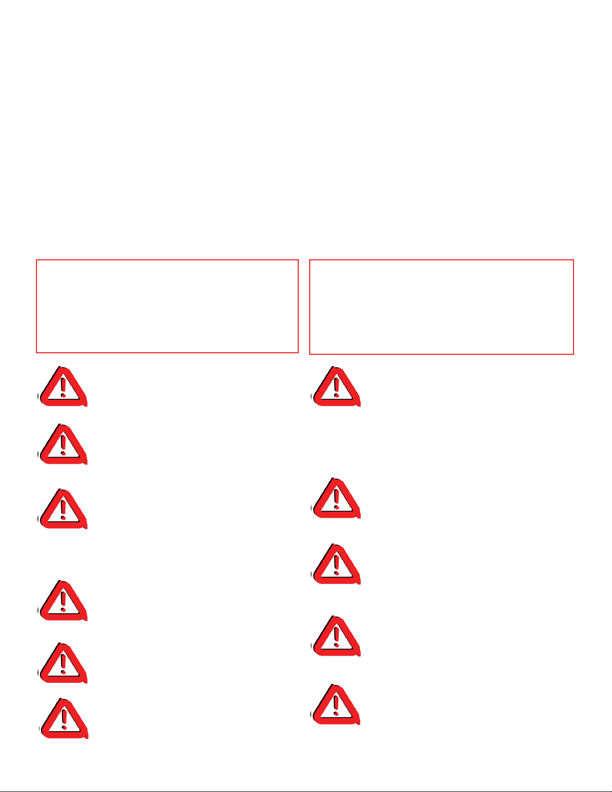
Package Contents: 3982 idrive™ Extension Spring Kit
RH.
LH.
RH.
LH.
Flag Brackets
Photoelectric Safety Sensors
W/Hardware
Owners Manual
Cable/Drum
Assembly
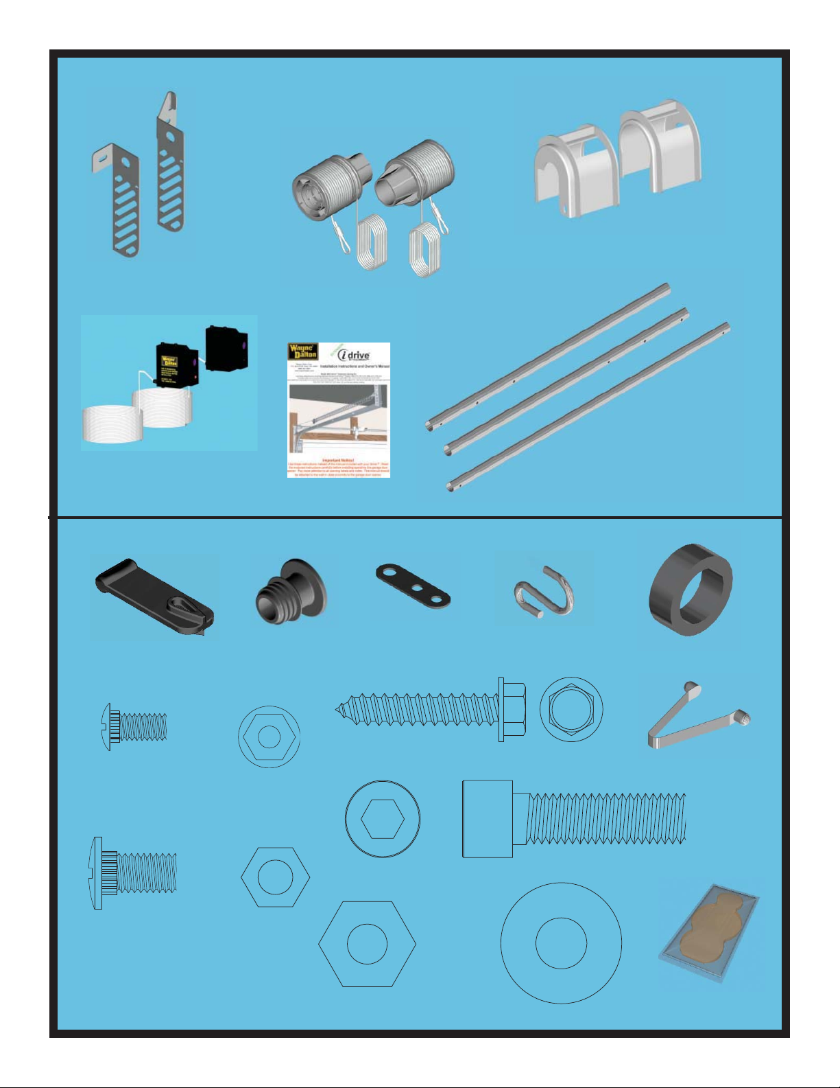
Hardware Kit: 3982 idrive™ Extension Spring Kit
RH.
LH.
Drum Wrap Set
(3) Cam Tubes
Cable Loop Tool
(2) 1/4-20 x 9/16”
Track Bolt
(4) 3/8-16 x 3/4” Truss
Head Bolt
(2) Drum Shafts
(2) 1/4-20
Flange Hex Nut
(4) 3/8-16
Hex Nut
(2) 1/2-13 Lock Nut
(2) 3-Hole Clip
(2) 5/16” x 1-5/8” Hex Head Lag Screw
(2) 1/2-13 x 2” Socket Head Cap Screw
(2) Large S-Hook
(4) 1/2” Flat Washer
(4) spacers
(2) Snap Buttons
Grease Packet (1)
4
Page 5
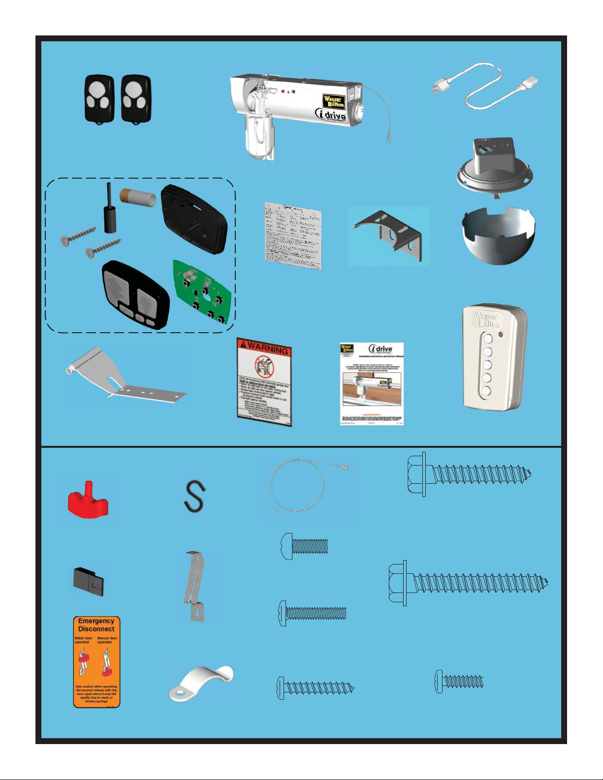
idrive™ Package Contents:
Three-button
Transmitter (2)
Wall Station Assembly
6’ Power Cord (1)
Opener
Lock Arm Assembly
Entrapment Label
idrive™ Hardware Kit:
“S” Hook (1)
Disconnect
Handle (1)
Wall Station
Reference Label
Owners Manual
Disconnect Cable (1)
Support
Bracket
1/4 x 1-1/2” Hex Head Lag Screws (4)
Light Fixture Assembly
w/ Screw & Diffuser
Jumpers (3)
Emergency
Disconnect Label (1)
Handle Bracket (1)
Cable Clips (4)
M5 x .8 x 12 Phillips
Pan Head Screw (1)
(For Lock Arm)
#6-32 x 3/4” Phillips
Pan Head Screw (1)
(For Light Fixture)
#6 x 7/8” Phillips Pan
Head Screws (4)
5
1/4 x 2” Hex Head Lag Screws (2)
#6-20 x 1/2” Phillips Pan
Head PL Screw (1)
(for disconnect handle)
Page 6
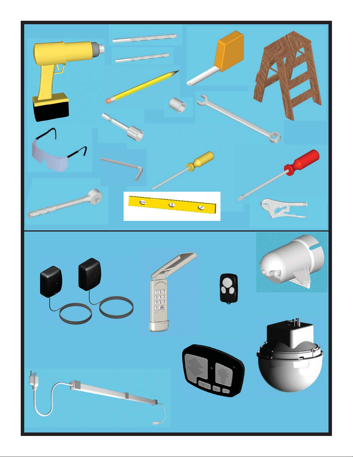
Tools Needed:
1/8” Drill Bit
3/32” Drill Bit
Power Drill
Pencil
7/16” Socket
1/2” Socket
9/16” Socket
3/4” Socket
7/16” Socket Driver
Safety Glasses
3/8” Hex Wrench
Ratchet
Level
Available Accessories: For idrive™
Tape Measure
Step Ladder
7/16” Wrench
1/2” Wrench
9/16” Wrench
3/4” Wrench
Flat Head Screw-
driver
Phillips Head
Screwdriver
Locking Pliers (2)
3-Button Mini RF Trans-
mitter
Model no: 3973
Part no: 302083
Infrared Safety Sensor
Model no: ML2
Part no: 301674
Power Cord Extender
Model no: 3960M, Part no: 302616
Keyless Entry RF
Transmitter
Model no: KEP2
Part no: 302078
5-Button Wall-Station RF
Transmitter
Model no: 3975
Part no: 302090
6
Low Headroom Kit
Part no: 302883
Deluxe Wireless Light Kit
Model no: 3950-ULDRE
Part no: 302097
Page 7
idrive™ Retro-fi t Installation
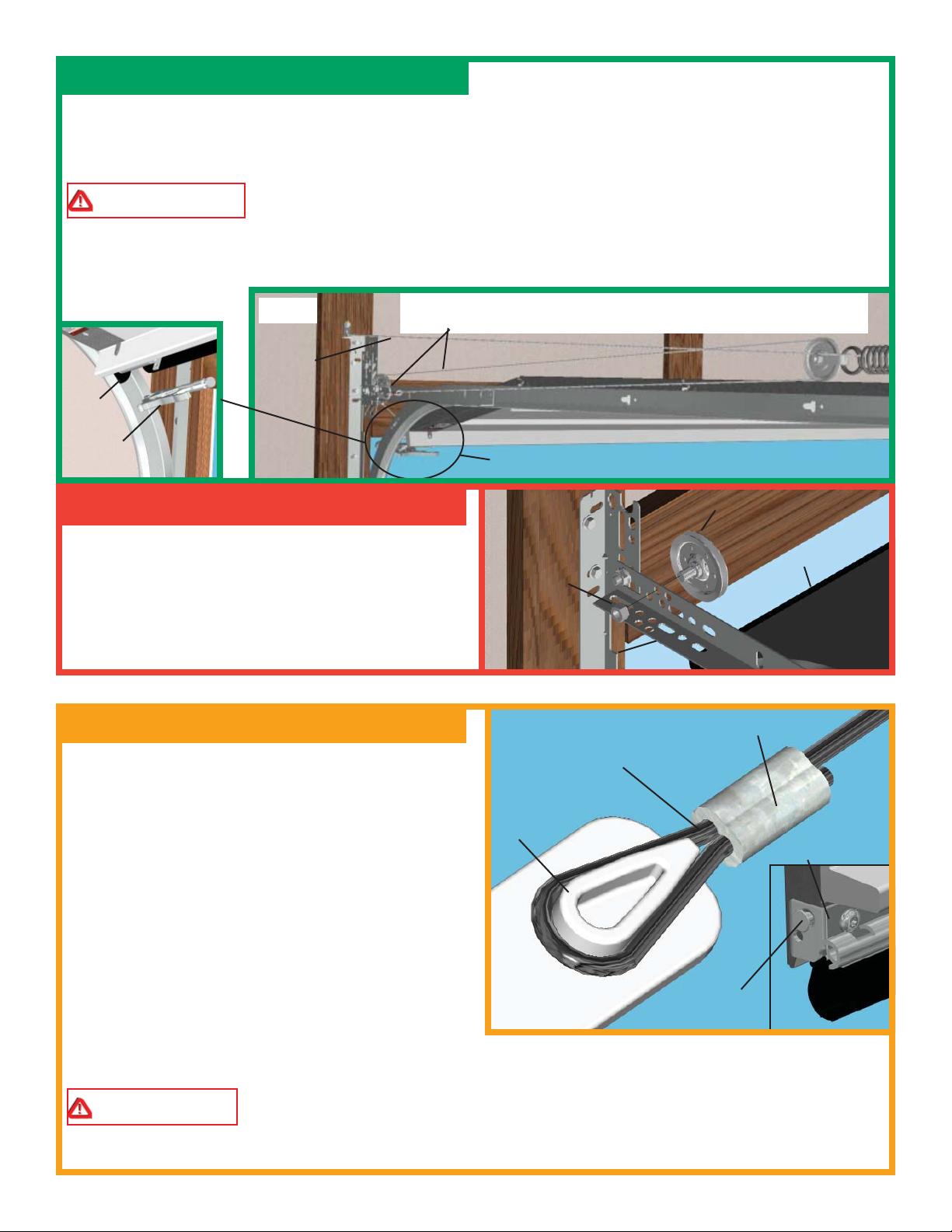
Step 1: Extension Spring Relief
Raise the door to the fully open position and clamp locking pliers to the back legs of both vertical tracks, below
the bottom rollers to prevent the door from falling (see Fig. 1). By opening the door, you release most of the
spring tension. Carefully unfasten the S-hook from the horizontal angle. Remove the counterbalance cable.
Leave extension spring with it’s sheave installed. Repeat for the other side.
WARNING COUNTERBALANCE SPRING TENSION MUST BE RELIEVED BEFORE RE-
MOVING ANY HARDWARE. A POWERFUL SPRING RELEASING IT’S ENERGY SUDDENLY CAN
CAUSE SEVERE, EVEN FATAL INJURY.
NOTE: Only remove springs when door is in the up position and visegrip pliers are attached to the
track.
BOTTOM
ROLLER
LOCKING
PLIERS
FIG. 1
SAFETY
CABLE
(LEAVE INSTALLED)
CAREFULLY REMOVE THE “S” HOOK AND COUNTERBALANCE
CABLE (REPEAT FOR THE OTHER SIDE)
ATTACH LOCKING PLIERS TO BACK LEG OF
TRACK BELOW ROLLER (BOTH SIDES)
Step 2: Remove Front Sheave
Disassemble the existing front cable sheaves. Typically the front sheave is secured with a bolt and nut to
the horizontal angle. Repeat for other side. (NOTE:
NUT
FRONT CABLE
SHEAVE
BOTTOM DOOR
SECTION
It may be helpful to refer to the original garage
door’s owner’s manual for removing parts from
the original door.)
HORIZONTAL
ANGLE
Extension idrive™ Installation
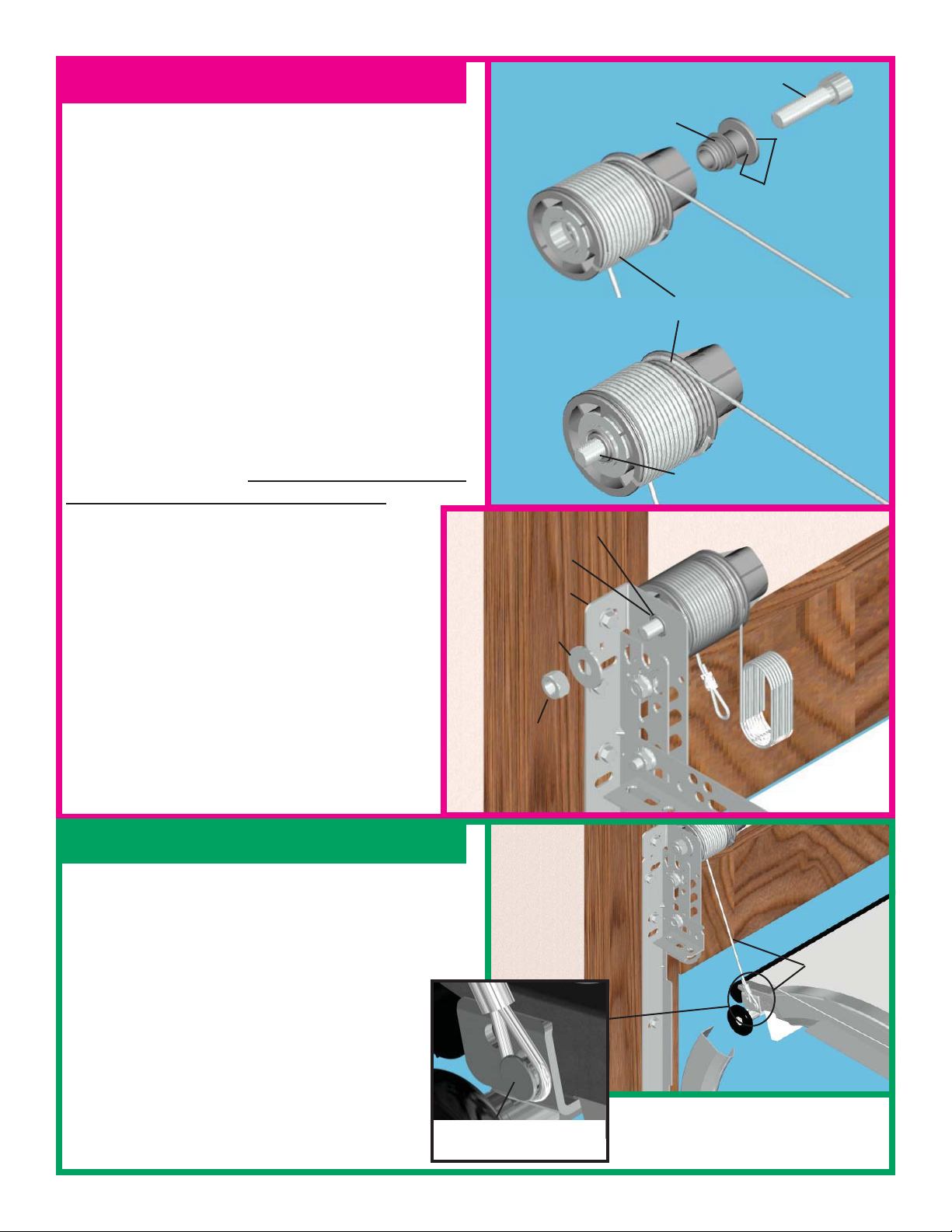
Step 3: Lifting Cable Loop
Locate the bottom bracket at the lower edge of the bottom
section. The lift cable will be attached to the brackets
milford pin. Measure the diameter of the head of the pin
and record the measurement. Locate the drum assemblies
provided with the kit. They will have a cable attached
with a loop formed on the end of the cable.
Locate the cable loop tool and install the loop over the
shape that corresponds to the milford pin head size you
measured. Use the larger size if the milford pin head size
is greater than or equal to 1/2”, and the smaller size if the
diameter is less than 1/2”. With the cable installed onto
the tool, pull the cable tight, forming it around the loop
tool. Remove the cable from the tool while holding the
cable so it does not slip in the crimp sleeve. Place the
crimp sleeve on a hard surface and using a hammer, hit
the crimp sleeve until it is squeezed tightly around the cable. Verify the loop has been set securely by pulling
on the loop. Repeat for the other cable. Set the drum/cable assemblies aside until needed.
PULL LIFTING CABLE
TIGHT SNUGGING THE
CABLE TO SIZE AROUND
THE FIXTURE
LOOP
TOOL
MILFORD PIN
CRIMP SLEEVE
BOTTOM
BRACKET
WARNING FAILURE TO CRIMP SLEEVE SECURELY TO CABLE, CAN CAUSE CABLE
TO SLIP OUT, ALLOWING DOOR TO FALL DURING OPERATION, RESULTING IN SEVERE OR
FATAL INJURY.
7
Page 8
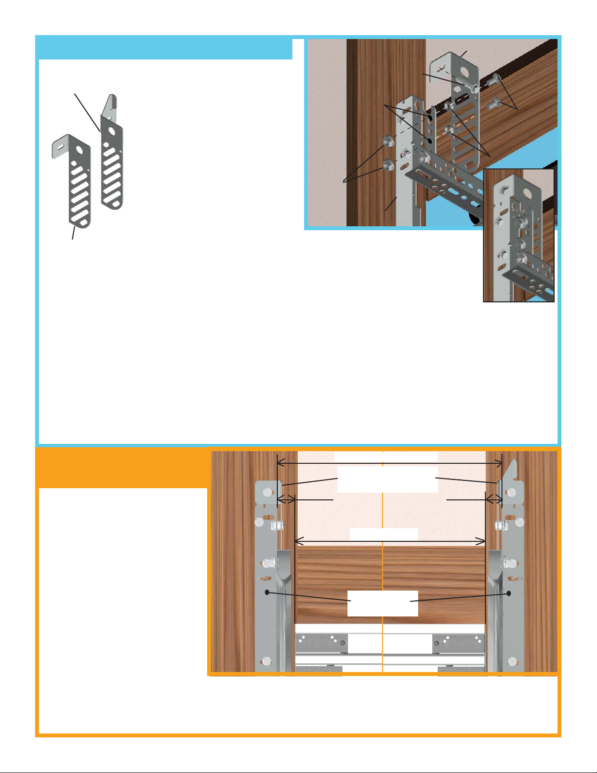
Step 4: Flag Bracket Installation
RIGHT HAND
FLAG BRACKET
There are two fl ag brackets (left
and right) provided. The right side
bracket has an extended fl ange at the
top. Align the left hand fl ag bracket
to the existing left fl ag angle, so the
top fl ange will be located to the top
edge of the existing fl ag angle.
Identify two locations that will allow the 3/8” bolts to go through both
the fl ag bracket and the existing fl ag
5/16 X 1-5/8”
LAG SCREW
DRILL (2) 3/8” DIA.
HOLES TO MATCH
SLOTS IN FLAG
BRACKETS
(2) 3/8”
NUTS
FLAG
BRACKET
(2) 3/8-16 X 3/4”
TRUSS HEAD
BOLTS
(2) SPACERS
angle.
FLAGANGLE
NOTE: In some instances there
LEFT HAND
FLAG BRACKET
may not be any holes in the existing fl agangles to mount the fl ag brackets. It will be necessary to drill two 3/8” dia. holes that will allow the
3/8” bolts to go through both the existing fl ag angles and the new fl ag
brackets. Once the holes are drilled proceed with the installation of the fl ag brackets as
shown in step 4.
BRACKET
INSTALLED
Insert the 3/8” bolts into the previously identifi ed slot in the fl ag bracket, insert a spacer onto the bolt and position the fl ag bracket to the existing fl ag angle. Attach the 3/8” nut and tighten. Secure the second bolt, spacer
and nut in the same manner. Make sure that the fl ag bracket is parallel with the existing fl ag angle.
IMPORTANT! Flag brackets must be level and plumb. Secure the top of the fl ag bracket with a 5/16” lag
screw in the slot provided. Repeat the procedure for the right hand bracket.
NOTE: Right and Left hand is determined from inside the garage, looking out.
Step 4A: Track Width
Conformation
For the extension spring torsion
1-3/4”
DOOR WIDTH + 3-1/2”
EXTENSION SPRING
FLAG BRACKETS
1-3/4”
tube to install correctly it is necessary that the distance between the
fl ag angles be correct. Measure the
DOOR WIDTH
distance between the existing fl ag
angles. The dimension needs to be
the width of the door + 3-1/2”. If
this is not what the track is set to,
then you must adjust the track so
that the mounting brackets meet
EXISTING
FLAG ANGLES
the requirment.To move the track it
may be necessary to loosen the bolts
in the fl ag angles and the brackets
mounting it to the jamb. Set the
track so it is 1-3/4” from the edge
of the door on both sides. Reinstall bolts in the jamb brackets and fl ag angles. Recheck dimensions before go-
ing to the next step.
8
Page 9
Step 5: Cable Drum Installation
NOTE: Do not remove shrink wrap from cable
drums until instructed to do so.
1/2-13 X 2” SOCKET
HEAD CAP SCREW
DRUM SHAFT
Cable drums are right and left. Be sure to check the
identifi cation on each drum to make sure the correct
drum is installed on its corresponding side.
Apply grease to both sides and outer diameter of the
fl ange of the drum shaft.
Insert the 1/2-13 x 2” socket head cap screw into the
drum shaft. Then insert the screw and shaft into the
drum so that the screw threads and drum shaft are
showing out past the drum bearing.
Install the drum/shaft/screw assembly into the 3/4”
hole in the fl ag bracket. Be sure the end of the shaft
is inserted into the hole in the fl ag angle.
Secure assembly with a 1/2” washer and 1/2”
lock nut.
Check to make sure the drum will rotate freely
on the shaft. If not, loosen 1/2” lock nut until the
drum is free to rotate. Repeat for opposite side.
DRUM SHAFT
3/4” HOLE
FLAG
BRACKET
1/2” WASHER
APPLY GREASE
TO DRUM SHAFT
FLANGE
CABLE DRUM
1/2-13 X 2” SOCKET
HEAD CAP SCREW
DRUM ASSEMBLY
(SHRINK WRAPPED)
Step 6: Bottom Bracket Lifting Cables
Locate the end of the lifting cable where the custom loop
was made earlier in the instructions. Carefully pull the
cable, bringing the loop to the milford pin located in the
bottom bracket on the edge of the bottom section. Secure
the cable loop around the milford pin, making
sure the loop is over the head of the milford pin
and around the smaller diameter. Repeat for the
other side.
MILFORD PIN ON
BOTTOM BRACKET
1/2” LOCK
NUT
LIFTING
CABLE
9
Page 10
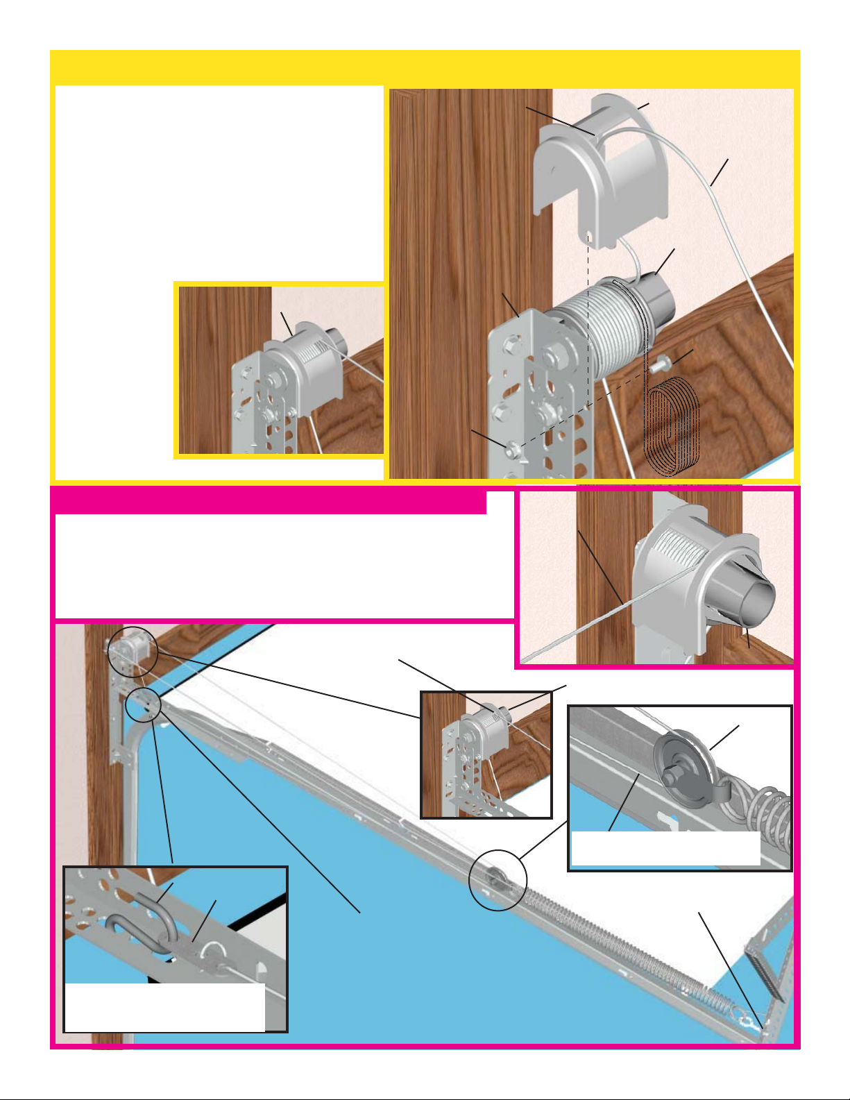
Step 7: Drum Wrap Installation
NOTE: Right and Left hand is determined
from inside the garage, looking out.
Drum wraps are right and left. Take the
extension spring cable and unroll it, thread
the free end of the cable through the
rectangular window of the drum wrap.
Position the drum wrap as shown
DRUM WRAP INSTALLED
RECTANGULAR
WINDOW
FLAG
BRACKET
1/4-20
FLANGE NUT
LEFT HAND
DRUM WRAP
EXTENSION
SPRING CABLE
CABLE
DRUM
1/4-20 X 9/16”
TRACK BOLT
Step 8: Extension Spring Counterbalance
NOTE: The door lifting cable and the extension spring cable are
wrapped oppositely on the drum.
Take the end of the extension spring cable, thread it through and
around the sheave located on the extension spring, then bring the
cable to the front of the track.
COUNTERBALANCE
CABLE ON DRUM
GROOVES
S-HOOK
3-HOLE
CLIP
ADJUST CABLE SO THAT
SPRING STRETCHES 1”, BY
RELOCATING S-HOOK OR ADJUSTING THE CABLE IN THE 3-HOLE CLIP
SECURE COUNTERBALANCE
CABLE WITH S-HOOK AND 3HOLE CLIP
EXTENSION SPRING
COUNTERBALANCE
CABLE
CABLE DRUM
COUNTERBALANCE CABLE
ON SPRING SHEAVE
SECURED TO FRAMING
MEMBERS
REVERSE
ANGLE
CABLE DRUM
SHEAVE
10
Page 11
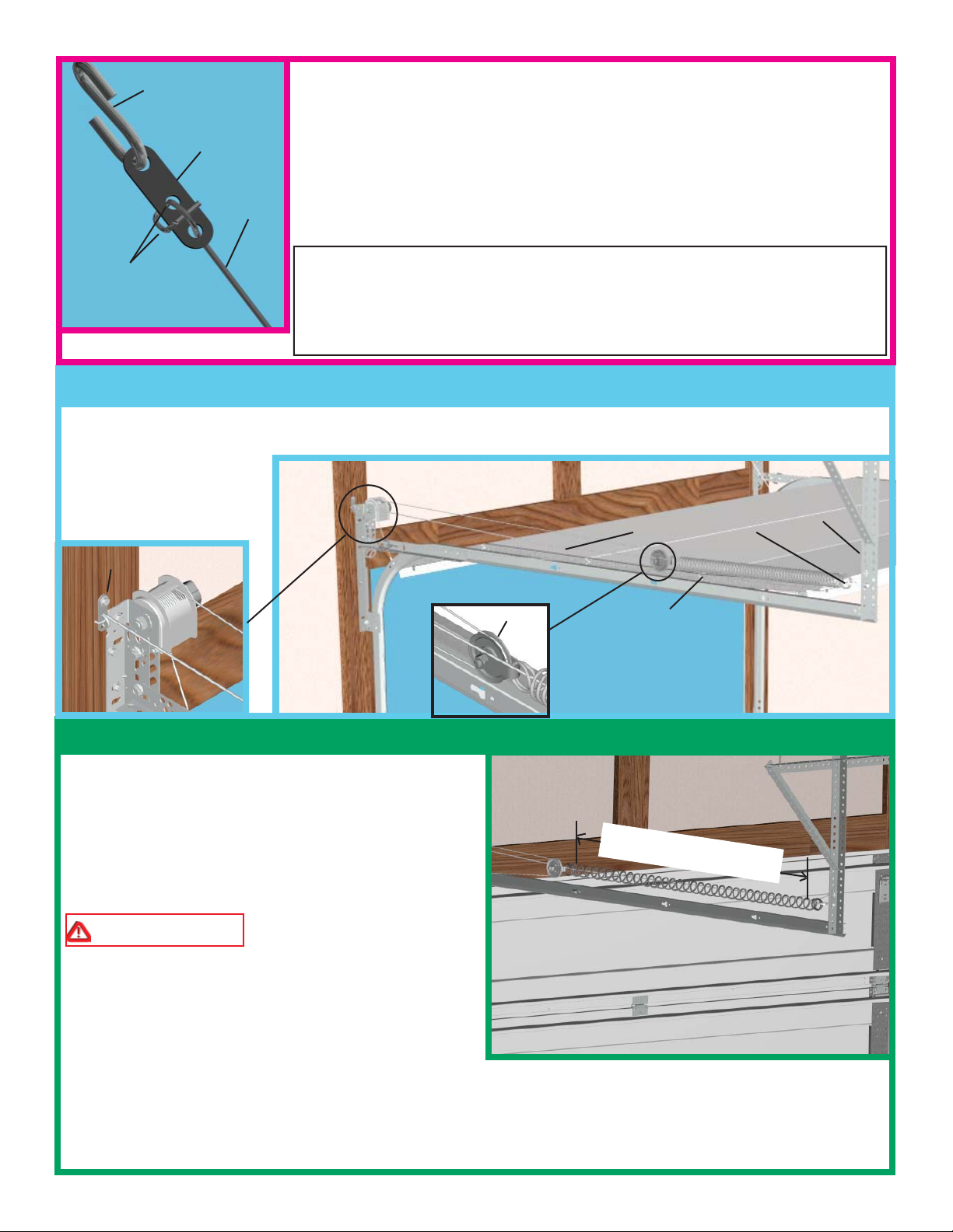
Attach the 3-hole clip as shown. Insert the S-hook into the 3-hole clip. Pull the
S-HOOK
3-HOLE
CLIP
cables taut ensuring the cable is on the sheave. Connect the cable to the horizontal angle. Repeat Step 8 for the opposite side of the door.
After the counterbalance cables are installed on both sides of the track, lift the
drum wrap to remove the shrink wrap from the cable drums. Re-insert the drum
wrap and match the hole in the drum wrap with the hole in the fl ag bracket.
CABLE
Secure the drum wrap to the fl ag bracket using (1) 1/4-20 x 9/16” track bolt and
1/4-20 fl ange nut (see Fig.7). Repeat for the other side.
SPRING ADJUSTMENTS: Adjust the counterbalance cables so that there is
TIE CABLE
THROUGH THE (2)
SMALLER HOLES
no more than 1” of spring stretch. This is done by adjusting the cable in the 3hole clip and/or moving the S-hook to another location on the horizontal angle.
Be sure that the left and right side counterbalance cables are adjusted to provide
the same amount of spring pre-tension on each side.
Step 9: Safety Cable Installation
Ensure that the safety cables installed on your door are not tangled with the extension spring cables. Contact
a professional garage door service technician if safety cables are not installed through each of the extension
springs on your door.
REAR SUPPORT
SAFETY CABLE
3 HOLE CLIP
Step 10: Lower the Door
Now that the counterbalance system is installed to the
garage door, remove the locking pliers and carefully
lower the door to the fully closed position. Be sure
the door descends uniformly by pulling the door down
from the center of the door and using correct gripping
points, such as a lift handle or lock handle.
WARNING TO AVOID SEVERE IN-
JURY DO NOT PLACE FINGERS OR HAND
BETWEEN SECTION JOINTS.
SHEAVE
EXTENSION SPRING
SPRING TENSION
EQUAL ON BOTH SIDES
Once the door is closed, measure the spring length on
both springs and verify the spring tension length is the
same for both springs. If they are not, raise the door,
re-attach locking pliers and repeat the CABLE ADJUSTMENT process in Step8.
IMPORTANT! Do not try to adjust springs while the door is in the closed (Down) position.
11
Page 12

Step 11: idrive™ Opener/Torque Tube Assembly
Locate the (3) pieces of cam shaped tube (Torque Tube).
Notice that one piece is smaller and will fi t inside the other two
pieces.
NOTE: Right and left hand are always determined from inside
the garage looking out.
Locate the idrive™ opener in the operator box. Look into the
opener’s left side to ensure the left hand bearing and the internal
(black) sleeve are aligned with the torque tube profi le. Once
aligned, slide the opener onto the smaller piece of tubing.
IMPORTANT! To avoid damage, tube must be assembled enter-
ing left side of opener and exiting right side.
NOTE: Hold the opener by the main
body. Do not hold by the motor.
As the right end of the torque tube enters the internal (black) sleeve, rotate
the opener back and forth slightly to
help aid alignment.
LEFT HAND
BEARING
TORQUE TUBE
AND BEARING PROFILES
ALIGNED
RIGHT HAND
BEARING
NOTE: Do not force the opener onto
the tube if misalignment occurs.
Continue sliding the opener onto the
torque tube. Align the right hand bearing with the torque tube and slide the
opener completely onto the torque
tube until the torque tube exits the
SMALL
TORQUE
TUBE
opener right hand bearing. Continue
sliding the opener to the center of the
torque tube.
Install the snap buttons into each end of the tube.
Take the two larger torque tubes and slide one over each end
of the smaller torque tube. Be sure that the end with the 3
sets of holes is toward the opener.
OPENER
POWER
CORD
MOTOR
SNAP BUTTONS
12
SMALL TORQUE
TUBE
Page 13

Step 12: idrive™ Opener/Torque Tube Assembly Installation
Push the outer torque tubes in until they are touching the opener. Be sure that the snap buttons are not engaged
in any of the outer tube holes. This will make the torque tube the shortest in length and allow enough room to
get the tubes into the drums. The torque tube can be adjusted to fi t a door width of 8’ to 10’ in 6” increments.
See fi gure above.
8’-0”
LEFT HAND
TORQUE TUBE
Door
Width
8’-0” hole 1 hole 1
8’-6” hole 2 hole 1
9’-0” hole 2 hole 2
9’-6” hole 3 hole 2
10’-0” hole 3 hole 3
Left Hand
Torque Tube
Right Hand
Torque Tube
1
3
2
SNAP BUTTONS
ENGAGED
10’-0”
Lift the iDrive™ opener/ torque tube assembly up to the drums. It may be
necessary to disconnect the motor from the torque tube to get the tube into
the drum. To disconnect, pull the cable coming out of the top right hand
side of the opener. This will disconnect the motor and allow the torque
tube to rotate inside the opener. Align one end of the tube to the “cam”
shaped hole in the drum. Once aligned, slide the tube into the
cable drum. Make sure it is all the way into the drum. Now take the op
posite end of the tube and slide it into the other drum. Extending the tube
so that the tube is all the way in both drums. When correct, the snap buttons will engage the set of holes for your door width.
Step 13: Secure idrive™ Opener
1
2
3
RIGHT HAND
TORQUE TUBE
TORQUE TUBE
PARALLEL AND
LEVEL WITH
TOP OF DOOR
MOTOR
(2) 1/4 X 2” LAG SCREWS
SPRING PAD
OPENER
SUPPORT BRACKET
TORQUE TUBE
PARALLEL AND
LEVEL WITH
TOP OF DOOR
MOTOR
OPENER
SPRING PAD
(2) 1/4-20 FLANGE HEX NUTS
Locate the spring pad. The spring pad is a vertical running board above the center of the door. Remove
(2) 1/4-20 fl ange nuts from bottom of opener. NOTE: Do not discard fl ange nuts. Place the support bracket
(in idrive™ hardware bag) underneath the opener, to the right side of motor, centered on spring pad. Level
the torque tube to the top of the door section with the idrive™ resting on the support bracket. Once torque
tube is level, secure support bracket to the spring pad with (2) 1/4 x 2” lag screws(operator hardware). Lift and
slide the opener over the support bracket, aligning the mounting studs with the bracket slots. Loosely fasten to
mounting studs with the (2) 1/4-20 fl ange nuts.
NOTE: Do not tighten 1/4-20 fl ange nuts to opener studs
at this time.
13
Page 14

Step 14: Disconnect Installation
Attach the loose disconnect cable
(located in opener hardware bag)
to the opener with the S-hook.
Close both ends of the S-hook to
lock assembly together.
Thread the disconnect cable
through the hole in right hand
fl ag bracket and remove all slack
between opener and right hand
fl ag bracket.
Mark a location on the right
jamb, 6 feet above the fl oor to
mount the handle bracket. Align
top of the bracket with the mark.
Fasten bracket to the jamb with
(2) 1/4 x 1-1/2” lag screws. Start the #6-20 x 1/2”screw
into the handle. Thread the disconnect cable through the
top of the handle bracket and then the handle. Locate
the handle in full upper position of handle bracket. Then
remove all cable slack between the opener and the top
of the handle bracket. Tighten #6-20 x 1/2” screw into
the handle until snug, and then tighten screw an additional 1 to 1-1/2 turns to secure cable to handle. Trim
off excess cable from bottom of the handle.
OPENER
CABLE
#6-20 X 1/2”
HANDLE
1/4 X 1-1/2”
LAG SCREW
S-HOOK
DISCONNECT
CABLE
RIGHT HAND
FLAG BRACKET
6’
(To bottom
of door)
NOTE: It is recommended that 1/4” lag screw loca-
tion be pilot drilled using 1/8” drill bit.
CAUTION: Pull cable only enough to remove the
cable slack. Pulling the cable more could cause opener
to disconnect from the torque tube.
Apply emergency disconnect label next to the mounted
bracket. Use mechanical fasteners if adhesive will not
adhere.
Using the emergency disconnect, pull disconnect handle
downwards and place it in the manual door operated
position. Use disconnect label for reference. Motor
will be rotated 90° from its packaged position.
NOTE: If motor does not pivot 90°, Refer to trouble-
shooting pages 34 and 35 of the iDrive™ Instructions
and Owner’s Manual.
14
HANDLE
BRACKET
MOUNTED
BRACKET
MANUAL DOOR OPERATED POSITION
EMERGENCY
DISCONNECT
CABLE
Page 15

Pre-Operation Installation
Step 15: Wall Station Installation
Locate a convenient place to mount wall station within
sight of the garage door. To keep wall station out of the
reach of children, measure at least fi ve feet up from the
fl oor and secure wall station base into wood wall framing using (2) phillips head screws. Use 2 of 3 holes
that best align with wood framing. Use anchors (not
included) when fastening to drywall or concrete.
CAUTION: Over tightening screws into wood could
deform plastic base and interfere with circuit board
snaps.
NOTE: Pilot drill mounting holes using a 3/32”
(3mm) bit.
Insert bottom of circuit board behind bottom snap of
wall station base. Pivot circuit board up and snap into
place. For best results, press on circuit board between
battery terminals.
(2) PHILLIPS HEAD
SCREWS
ALTERNATE SCREW LOCATION
CIRCUIT
BOARD
BOTTOM
SNAP
Insert battery onto circuit board being careful to match
(+) positive battery marking with (+) circuit board
marking. Align wall station cover/button assembly
with base. Press cover assembly over base until cover
BASE
COVER
ASSEMBLY
snaps into place. A uniform seam between the cover
and base indicates a proper installation.
BATTERY TERMINALS
PRESS HERE
WALL STATION
REFERENCE LABEL
ENTRAPMENT
LABEL
Apply wall station reference label and entrapment label
in a convenient location next to the wall station.
15
Page 16

Step 16: Multi-Opener/Light Fixture Programming
NOTE: Skip this step if installing only one idrive™ opener.
Switch Settings: Light Fixture
If installing more than one opener in the same garage, the light fi xtures can be set to function only with a selected
opener. Leaving the light fi xture as is from the factory may cause all light fi xtures to light when any one of the
openers are activated. The opener jumpers and light fi xture switches need to be matched to allow for the opener
to activate a specifi c light fi xture. To adjust switch
location on light fi xture, slide switches on top of light
fi xture housing.
LIGHT FIXTURE
-A- -B-
-C-
-D-
SWITCHES
Jumper Settings: Opener
On the right side of the opener, insert jumper(s) provided
in the hardware pack, to match the switch setting of the
light fi xture.
-A- -B- -C- -D-
NO JUMPERS
FOR PINS 1 & 2
PIN 1
-A-
SWITCH 1 (OFF)
SWITCH 2 (OFF)
(FACTORY
SETTING)
-B-
SWITCH 1 (ON)
SWITCH 2 (OFF)
PINS 1 & 2
-C-
SWITCH 1 (ON)
SWITCH 2 (ON)
-D-
SWITCH 1 (OFF)
SWITCH 2 (ON)
PIN 2
Jumper Settings
Light Fixture
Detail
-A- = -A-
-B- = -B-
-C- = -C-
-D- = -D-
Opener
Detail
OPENER
When the light fi xture switches and the opener jumpers are matched, the light fi xture will respond to its
matched opener.
16
Page 17

Step 17: Light Fixture Installation
IMPORTANT! The light is turned on and off by an infrared (IR) signal sent from the opener to the light.
Therefore, the light must be mounted in a location where it can always “see” the front face of the opener.
Locate a duplex receptacle within line of sight of opener, when the door is in the open position.
Disconnect power to the receptacle at the fuse/breaker box before proceeding.
WARNING TO REDUCE THE RISK OF ELECTRICAL SHOCK, THIS EQUIPMENT HAS A
GROUNDING TYPE PLUG, THAT HAS A THIRD
(GROUNDING) PIN. THIS PLUG WILL ONLY FIT
INTO A GROUNDING TYPE OUTLET. IF THE
NOTE: RECEPTACLE COVER MUST BE INSTALLED
IN-BETWEEN THE LIGHT FIXTURE AND THE CEILING
PLUG DOES NOT FIT INTO THE OUTLET, CONTACT A QUALIFIED ELECTRICIAN TO INSTALL
DUPLEX
RECEPTACLE
THE PROPER OUTLET. DO NOT CHANGE THE
PLUG IN ANY WAY.
LIGHT FIXTURE
WARNING TO AVOID ELECTRICAL
SHOCK, DISCONNECT POWER TO THE RECEPTACLE AT THE FUSE/BREAKER BOX BEFORE
PROCEEDING.
WARNING DO NOT INSTALL THE
LIGHT FIXTURE INTO A RECEPTACLE WITH A
METAL FACEPLATE.
NOTE:
is in the open position. There must be no obstruction
between the light fi xture and the opener for light fi xture
to work properly.
CEILING MOUNTING
Remove the center screw in the receptacle cover. Holding receptacle cover in place, insert light fi xture into
the receptacle that has the ground hole farthest from
center screw hole. Remove center hole plug from light
fi xture to expose the screw hole. Secure light fi xture to
receptacle with a #6-32 x 3/4” phillips pan head screw.
Replace hole plug into the screw hole in the light fi xture.
plug must be in place prior to using the light fi xture.
Loosen thumb screw and rotate light fi xture’s bottom
section to align the receiving module, side to side,
with the sending LED on the opener. Re-tighten thumb
screw, don’t over tighten. Rotate receiving module to
align, up and down, with the sending LED.
Door must clear light fi xture when the door
NOTE: For temperature protection, the hole
HOLE PLUG
75W (MAX)
LIGHT BULB
(NOT INCLUDED)
THUMB
SCREW
ALIGN
RECEIVING
MODULE
AIM AT
IR LED
#6-32 X 3/4”
PHILLIPS
PAN HEAD
SCREW
DIFFUSER
OPENER
Screw a maximum 75W light bulb into light socket and
snap diffuser into light fi xture. Turn receptacle power
back on at fuse/breaker box. The light should blink
one time when the power is re-established.
NOTE: An accessory power outlet receptacle (600 Watt
Maximum) is provided on the light fi xture.
SENDING IR
LED
17
Page 18

Light Fixture Installation (Continued)
WALL MOUNTING
Depending on location, the light
fi xture may need to be adjusted from
its packaged position.
When mounting on a wall parallel
to the opener, rotate the receiver
module inward to a maximum of
90° until the receiver module is
best aligned with the sending LED.
Mount light to a receptacle and align
the receiving module per previous
instructions.
To mount the light fi xture on a wall
perpendicular to the opener, leave
receiving module in the factory
position.
Mount the fi xture to a receptacle
and align receiving module per
previous instructions. Insert hole
plug into the screw hole.
NOTE: RECEPTACLE COVER MUST BE INSTALLED IN BETWEEN THE
LIGHT FIXTURE AND THE WALL
LIGHT BULB - 75W
MAX. (NOT INCLUDED)
#6-32 X 3/4”
PHILLIPS PAN
HEAD SCREW
DIFFUSER
HOLE PLUG
RECEIVING
MODULE
DUPLEX RECEPTACLE
ROTATE 90°
(IF NECESSARY)
LIGHT
FIXTURE
SOCKET
NOTE: For temperature protection, the hole plug must be in place prior to using the light fi xture.
Screw in a maximum 75W light bulb into light socket and snap diffuser into light fi xture. Turn receptacle
power back on at fuse box.
Final alignment of the light fi xture to the opener may be needed once the opener is electrically connected.
18
Page 19

Step 18: Photoelectric Safety Sensor Installation
Select a mounting position 5 inches above the fl oor
to center line of wall mounting bracket. The sending and receiving units should be mounted inside the
door opening to minimize any interference by the sun.
However, the sensors should be mounted as close to the
door track or inside edge of the door as possible to offer
maximum entrapment protection. It is very important
that both wall brackets be mounted at the same height
for proper alignment.
The brackets may be temporarily mounted to the jamb
with a 1” fl at head nail (provided) using the small hole
above the slot. Using two 5/16 x 1-1/2” lag screw (provided), permanently mount the wall mounting brackets
to both door jambs. In some installations it may be necessary to attach a wooden spacer to the wall to achieve
the required clearance.
(1) 5/16 X 1-1/2”
LAG SCREWS
NUT
WASHER
WALL
MOUNTING
BRACKET
“U”
BRACKET
NAIL
5”
Attach the “U” brackets to the wall brackets with a
1/4-20 carriage bolt, washer and nut (provided). Insert
the bolt from the inside of the “U” bracket and hand
tighten only at this time.
Identify which side of the garage door opening (if any)
is “likely” to be exposed to the sun. Since sunlight
may affect photoelectric sensors, you should mount the
sending unit (not the receiving unit) on the side of the
door opening most exposed to the sun.
NOTE: If wires must be lengthened or spliced into
prewired installation, use wire nuts or suitable connectors.
Attach the sending and receiving units to the “U” brackets by inserting their tabs into the respective holes.
1/4-20 X 1/2”
CARRIAGE BOLT
RECEIVING UNIT
LED ALIGNMENT
LIGHT
TAB HOLES
BOTTOM & TOP
SENDING UNIT
HAS NO LED
LIGHT
19
TABS
BOTTOM & TOP
Page 20

Photoelectric Safety Sensor
Installation Continued
Uncoil wires from photoelectric sensors and route
wires up garage wall and along door header towards
.
the right side of the opener
tube and tack wires in place with insulated staples (not
supplied). Take care to run wires in a location where
they will not interfere with the operation of the door
and do not staple through wire.
Connect photoelectric sensors to the opener terminal
block in right side of the opener. Separate wire ends
and strip about 1/2” of insulation off each of the wire
ends. Insert a 3/32” (2,5 mm) max. width fl athead
screwdriver into the lower hole #1 of the terminal
block. Twist screwdriver to open wire clamp in upper hole #1 of terminal block. Insert both sender and
receiver solid white wires into upper hole #1 until the
wires bottom out and release screwdriver tension. Insert both sender and receiver wires (white with black
strip) into upper hole #2 by the same process on lower
hole #2 of terminal block. Once wires are connected
install jumper on to the left most set of pins labeled
“PE”, located on the front of the opener.
Route wires above torque
WIRE ROUTING
INSERT SENDER
WIRES
IMPORTANT! Keep sender/receiver wires away
from moving members.
Be sure to observe polarity. Pull on external wires to
test for secure connection. Check that the wires are
stapled in place and staples have not cut wire insulation.
INSERT WIRES INTO
UPPER HOLES
OPENER
SENDING IR LED
INSERT
RECEIVER
WIRES
RIGHT HAND SIDE
VIEW OF OPENER
SOLID
WHITE WIRES
WHITE WIRES
WITH BLACK
STRIPES
INSERT SCREWDRIVER INTO
LOWER HOLES
VIEW OF THE OPENER
FROM THE FRONT
JUMPER INSTALLED
ON PINS “PE”
20
Page 21

Step 19: Power Connection (Standard Wiring)
Plug the female end of power cord into the inlet connector on the right side of opener. Plug the other end of
the opener power cord into the nearest convenient power receptacle. (If the power cord is not long enough
to reach the closest receptacle, the idrive™ Powercord Extender kit is available, otherwise contact a service
person for further options.) As soon as power is applied to the opener, the light fi xture will light up. If the
light fi xture does not light, adjust the receiver module alignment. Unplug, then plug back in the power cord.
Repeat this process until the light comes on. Ensure there is no obstruction between the opener and the light
fi xture. Refer to Step 17: Light Fixture Installation for the alignment procedure.
Excess power cord length must be routed and contained safely away from any moving members.
NOTE: Do not permanently attach power cord to building!
Use only the fl exible plastic clips supplied with the opener
WARNING TO REDUCE THE RISK OF
ELECTRICAL SHOCK, THIS EQUIPMENT HAS A
GROUNDING TYPE PLUG, THAT HAS A THIRD
(GROUNDING) PIN. THIS PLUG WILL ONLY FIT
INTO A GROUNDING TYPE OUTLET. IF THE
PLUG DOES NOT FIT INTO THE OUTLET, CONTACT A QUALIFIED ELECTRICIAN TO INSTALL
THE PROPER OUTLET. DO NOT CHANGE THE
PLUG IN ANY WAY.
LIGHT FIXTURE
PLUG INTO NEAREST
PLASTIC CLIPS
CONVENIENT POWER
OUTLET
#6 X 7/8 WOOD
SCREWS
POWER CORD
FEMALE END
OPENER
POWER OUTLET
RECEPTACLE
21
POWER CORD
DISCONNECT
CABLE
NO INTERFERENCE BETWEEN
POWER CORD AND DISCONNECT
CABLE
Page 22

Step 20: Power Connection (Permanent Wiring Option)
Where required by local codes, the opener can be permanently wired. Services of a licensed electrician can
be obtained to perform the following permanent wiring procedure.
WARNING DISCONNECT POWER AT FUSE/BREAKER BOX BEFORE PROCEEDING.
Using a phillips head screwdriver, remove the two screws from the right hand cover and unplug motor power
cable. Remove right hand cover from the opener to expose electronics and wiring.
Remove potentiometer gear and fi nishing plug. Unsnap the circuit board from the chassis stand-offs and
remove the circuit board as shown. NOTE: Do not disconnect the two ground wires (A & B) from the circuit board or the chassis. Cut three wires, leading to the inlet connector, at the base of the connector. Route
wires inside of the conduit through the top hole in the opener Using wire nuts, splice each conduit wire with
the corresponding wire inside the opener as follows: opener black (line), opener white (neutral), and opener
yellow and green (ground). Reinstall the circuit board back into the opener chassis and snap the board back
into the chassis stand-offs. NOTE: Make sure antenna wire is routed through the chassis grommet when
board is installed. Confi rm pot position* shown below. Reinstall the potentiometer gear, right hand cover,
and screws. Plug in the motor power cable.
ANTENNA
GROMMET
POTENTIOMETER GEAR
GREEN &
YELLOW
(GROUND)
“A”
“B”
REMOVE AND DISCARD FINISHING
PLUG
INLET
CONNECTOR
CUT
WIRES
HERE
CHASSIS
STANDOFF
*POTENTIOMETER
GEAR CLIP
*POSITION POT NUT 1/16” - 1/8”
AWAY FROM LEFT STOP
22
WHITE
(NEUTRAL)
BLACK
(LIVE)
Page 23

Step 21: Securing the Opener
With the emergency disconnect still in the
manual door operated position: Manually
raise the door to the full upward position.
Then, manually lower the door to the full
closed position verifying freedom of movement and good door balance.
Tighten both 1/4-20 fl ange nuts, securing the
opener to the support bracket.
NOTE: Good door balance and freedom of
movement are critical to the safety and performance of the door opener. If door is very heavy
to lift or if springs are too tight making door hard
to close or if door sticks or binds in the track,
now is the time to correct it.
1/4-20 FLANGE NUTS
SUPPORT BRACKET
Step 22: Photoelectric Safety Sensor Alignment
IMPORTANT! - This infrared safety sen-
sor sends an invisible beam of light from
IN
the sending unit to the receiving unit across
the pathway of the door. The door opener
will not operate until the safety sensor is
connected to the power unit and properly
aligned. If the invisible beam of light is obstructed, an open door cannot be closed by
OUT
1/4-20 CARRIAGE BOLTS
the transmitter or a momentary activation of
the wall mounted push button. However, the
door may be closed by holding your fi nger
on the wall push button (constant pressure)
For this adjustment bend bracket at
until the door travels to a fully closed position. The safety sensors must be aligned by
moving the sending and receiving units in
or out (see Fig. 1) until the alignment light
on the receiving unit comes on. The
1/4-20” carriage bolt can be loosened to
move the unit in or out, as required. If you have diffi culty aligning beams, check that both brackets are mounted
at the same height and remount if necessary. Additional minor adjustments can be made by lightly bending the
mounting brackets (see Fig. 2).
FIG. 1
Top View
Align in Center
(In/Out)
FIG. 2
wall mount
Top View
Align in Center
IN
OUT
WARNING FAILURE TO MAKE ADJUSTMENTS COULD RESULT IN SEVERE OR FATAL
INJURY.
Once the alignment light comes on, tighten all bolts and mounting screws. Finish securing all wire making sure
not to break or open any of the conductors. Loop and secure any extra wire.
23
Page 24

Step 23: Wall Station Security Code Change and Programming
NOTE: The user must change the wall station’s security code before using the wall station.
This code setting sequence is only required the fi rst time the wall station is used.
Overview: When changing the wall station’s security code, the user will have to hold the light button down
for approximately 10 seconds, then release the button momentarily, and fi nally hold the button down again
for approximately 5 seconds.
Changing the wall station’s security code:
1. Press and hold the wall station’s light button for ap-
proximately 10 seconds until the wall station’s LED
begins to blink rapidly. Once the LED starts blinking
release the wall station’s light button; the LED will
turn off.
2. Press and hold the wall station’s light button again
(LED will light) for approximately 5 seconds. After
approximately 5 seconds the LED will begin to blink
on and off. Release the light button. The wall station’s
LED will blink on and off three times indicating a successful security code change.
The wall station is now ready to be programmed to
the opener.
Wall Station Programming
To program wall station:
1. Verify the emergency disconnect handle is in the
manual door operated position (lower position). This
is for safety reasons.
2. On the front cover of the opener, press and release
the red program button; the opener will beep once,
indicating activation of the program mode. The opener
will remain in program mode for 30 seconds.
3. Press and hold the wall station light button until the
opener beeps one time. The wall station is now
programmed.
4. Return the emergency disconnect handle to the motor operated position (upper position).
LIGHT BUTTON
LED
MOTOR IN UP POSITION
OPENER
RED PROGRAM
BUTTON
No beeping response of the opener during the wall
station programming indicates a programming failure.
Repeat programming Steps 1-4.
NOTE: Programming failure can occur during the
wall station programming if the remote control is too
close to the opener during the programming sequence.
Perform the programming with a minimum of six feet
between the remote control and the opener.
HANDLE IN MANUAL OPERATED POSITION
24
LIGHT
BUTTON
Page 25

NOTE: The fi rst wall station command, after programming, will only move the door through
a six-inch up/down cycle. Normal door operation will occur on the second usage of the wall
station.
NOTE: The opener can be activated by up to six remote control devices (including wall sta-
tion, transmitter, and keyless entry devices.) If a seventh control is programmed, the fi rst of the
programmed controls will be overridden and will no longer activate the opener.
CAUTION: For safety reasons, manually disconnect the opener from the door using the
emergency disconnect handle prior to erasing remote controls. To clear programming of
MOTOR
OPERATED
POSITION
all remote control devices, press and hold the opener’s program button for approximately ten
seconds. When the opener beeps three times, all remote controls are erased.
Step 24: Install Routine
The install routine automatically sets the door open and
close limits and calibrates obstruction sensing. During
install routine, the door will move up and down twice.
Always keep a moving door in sight and away from
people and objects until it is completely closed.
WARNING TO AVOID INJURY, NO
ONE SHOULD CROSS THE PATH OF A MOVING
DOOR!
NOTE:
However, if an object such as a ceiling beam obstructed the door from opening completely, set a custom upper
limit during the install routine, Step 24 b.
NOTE: The door must be in its fully closed position and the disconnect handle must be in the motor operated
position (upper position) to initiate the install routine.
If no obstructions interfere with the door when manually opened and closed, proceed to Step 24 a.
UP/DOWN
BUTTON
PROFILE
BUTTON
Step 24 a: Install routine with standard upper limit
Press and hold the profi le button for fi ve (5) seconds. The opener will beep twice, indicating the activation of
the install routine, release the profi le button. The door will now move to the full open position and stop. Then,
the door will close completely. Next, the door will go through one more up/down cycle. Once this is complete,
the door limits are set and the installation is complete.
Step 24 b: Install routine with custom upper limit
Press and hold the profi le button for fi ve (5) seconds. The opener will beep twice, indicating the activation of the
install routine. When the door moves to the desired height, at least four feet off the ground, press the up/down
button on the wall station. The door will stop and then close completely. Next, the door will go through one
more up/down cycle. Once this is complete, the door limits are set and the installation is complete. Alternately:
After an install routine has been completed, the door can be disconnected and manually moved to the desired
upper limit. Reconnect door and initiate a new install routine from the new upper position.
25
Page 26

Step 25: Detent Adjustment (if required)
IMPORTANT! - FOR SYSTEM SECURITY: The motor is de-
signed to pivot down after the door closes completely. If the motor
does not pivot or pivots too soon, the detent may need to be adjusted
in order for the door lock feature to work properly.
IMPORTANT! Before making any detent pin adjustments, check
and adjust door balance. Door should not raise off of fl oor with
spring tension alone, nor should it free fall from any open position.
The normal amount of pressure the opener uses to pivot the motor
downward is preset at the factory via the detent pin adjustment
screw. Due to variations in door installations, a detent pin adjustment may be needed in order to properly pivot the motor.
A.) If the motor does not pivot down, or pivots down only partially, the detent pin is set too hard. Using a fl at
head screwdriver, turn the detent pin COUNTER CLOCKWISE in 1/4 turn increments. Operate the door to
confi rm each adjustment. If the motor does not pivot on door closing adjust detent pin again. Repeat procedure
until motor pivots to full down position when the door is completely closed.
B.) If the motor pivots down prematurely (before the door is completely closed) or if the motor is “slapping”
too aggressively against the top of the door, the detent pin is set too soft. Using a fl at head screwdriver, turn
the detent pin CLOCKWISE in 1/4 turn increments. Operate the door to confi rm each adjustment. If the motor
pivots to soon, adjust detent pin again. Repeat procedure until motor pivots to full down position when the
DETENT PIN
Step 26: Lock Arm Installation
Place the emergency disconnect in the
manual operated
position, motor will
pivot to the up position. Insert the lock
arm into the motor
1
3
2
4
MOTOR
LOCK
ARM
groove and align the
lock arm to the #4 hole.
Secure the lock arm to the motor with (1) M5 x 0.8 phillips
pan head screw. After assembly of the lock arm, manually
M5 X 0.8 PHILLIPS PAN HEAD SCREW
MOTOR
GROOVE
raise and lower the door and verify that the lock arm does
not interfere with the door. If there is interference between
the door and the lock arm, remove the pan head screw and align to the #3hole. Secure with the phillips pan head
screw. Try manually raising and lowering the door until there is clearance between the door and the lock arm.
NOTE: Do not operate the door if there is interference between the lock arm and the door. Reconnect the
Step 27: Custom Settings
Custom pet position: Normal install routine sets the pet position to approximately eight inches above the ground. The pet opening height may be
changed to open anywhere between 8” and 30” above the ground. To change
the automatic pet opening height refer to the following procedure:
1. After completion of the normal install routine, with the door in the closed
position, place the disconnect handle in the manual operated position.
26
UP/DOWN
BUTTON
PET BUTTON
Page 27

Manually position the door to the desired pet opening height (between 8” and 30” above ground) and return
disconnect handle to the motor operated position.
2. Simultaneously depress the pet and up/down buttons on the wall station. The opener will beep once. The
pet button is now programmed to automatically open the door to this custom height.
NOTE: The opener will NOT accept programmed pet lock position if door is below 8” or higher than 30”.
NOTE: Activation of the normal install routine will reset the pet position to the default eight inch target
height. For use of the pet button see Operation section.
Step 28: Photoelectric Obstruction Sensor Test
Starting with the door in the fully open
position, place a 6” high object on the
fl oor progressively one foot from the left
side of the door, center of door and one
foot from the right side of the door. In
each position, activation of the opener
with the wallstation up/down button
should cause the door to move no more
than one foot, stop and then reverse to
fully open position. The same 6” high
object when placed on the fl oor, while
door is closing, should also cause the door to reverse.
6”
12”
12”
WARNING WHEN PERFORMING THIS PART OF THE TEST, DO NOT PLACE YOURSELF
UNDER DESCENDING DOOR, OR SEVERE OR FATAL INJURY MAY RESULT.
WARNING IF THE OPENER DOES NOT RESPOND PROPERLY, OR FAILS THESE TEST,
HAVE A QUALIFIED SERVICE PERSON MAKE NECESSARY ADJUSTMENTS/REPAIRS. FAILURE
TO MAKE ADJUSTMENTS COULD RESULT IN SEVERE OR FATAL INJURY.
Step 29: Contact Obstruction Test
After installing the opener, the door must reverse
when it: contacts a 1-1/2” (38mm) high object (or a
2 x 4 board laid fl at) on the fl oor. To verify proper
operation:
1. Using the wall station, activate the door to the fully
open position .
2. Place a 2 x 4 board laid fl at on the garage fl oor
under the door path.
3. Activate the door to the closed position with the
wallstation; upon contacting a solid object, the door will stop, then reverse direction within two seconds and
travel to the full open position.
If the door does not respond to the required tests, remove 2 x 4 and repeat install routine making sure the
door is in the fully closed position prior to activation. If problem persists contact Wayne Dalton Customer
Service (888) 827-3667
CENTER OF
DOOR
2 X 4 LAID FLAT
ON FLOOR
WARNING IF OPENER DOES NOT RESPOND PROPERLY AND FAILS EITHER OF THE
TWO TESTS (28 AND 29), DOOR MAY CAUSE A SEVERE OR FATAL INJURY. HAVE A QUALIFIED
27
Page 28

Step 30: Transmitter Security Code
Change and Programming
NOTE: The user must change the transmitter’s security
code before using the transmitter.
This code sequence is only necessary the fi rst time the
transmitter is used.
Overview: When changing the transmitter’s security
code, the user will have to hold the large button down
for approximately 10 seconds, then release the button
momentarily, and fi nally hold the button down again for
approximately 5 seconds.
CHANGING THE TRANSMITTER’S SECURITY
CODE:
1. Press and hold the large transmitter button for approxi-
mately 10 seconds until the transmitter’s LED begins to
blink rapidly. Once the LED starts blinking, release the
large transmitter button; the LED will turn off.
2. Press and hold the large transmitter button again
(LED will light) for approximately 5 seconds. After approximately 5 seconds the LED will begin to blink on
and off. Release the large button. The transmitter’s LED
will blink on and off three times indicating a successful
security code change. The transmitter is now ready to
be programmed to the opener.
MOTOR IN UP POSITION
OPENER
RED PROGRAM
BUTTON
LARGE
BUTTON
TRANSMITTER PROGRAMMING:
HANDLE IN MANUAL
OPERATED POSITION
To program transmitter:
1. Place the emergency disconnect handle in the manual door operated position. This is for safety reasons.
2. On the front cover of the opener, press and release the red program button; the opener will beep once, indi-
cating activation of the program mode. The opener will remain in program mode for 30 seconds.
3. Press and hold the desired transmitter button until; the opener beeps once. The transmitter is now programmed.
4. Return the emergency disconnect handle to motor operated position.
NOTE: No beeping response of the opener during the transmitter programming indicates a programming fail-
ure. Repeat programming 1-4.
NOTE: Programming failure can occur during the transmitter programming if the remote control is too close
to the opener during the programming sequence. Perform the programming with a minimum distance of six
feet between the remote control and the opener.
NOTE: The fi rst transmitter command, after programming, will only move the door through a six-inch up/down
cycle. Normal door operation will occur on the second usage of the transmitter.
NOTE: The opener can be activated by up to six remote control devices (including wall station, transmitter,
and keyless entry devices.) If a seventh control is programmed, the fi rst of the programmed controls will be
overridden and will no longer activate the opener.
CAUTION: For safety reasons, manually disconnect the door from opener using the emergency discon-
nect handle prior to erasing remote controls. To clear programming of all remote control devices, press
and hold the opener’s program button for approximately ten seconds. When the opener beeps three times, all
remote controls are erased.
28
Page 29

Step 31: Programming HomeLink™ to idrive™
NOTE: This step can only be done on automobiles equipped with the HomeLink™ System.
CAUTION:
During programming, the garage door may operate. Pull the emergency disconnect handle to put the operator
in the manually operated position. Make sure people and objects are out of the way of the moving door to
prevent potential harm or damage.
NOTICE: Programming HomeLink™ requires Wayne-Dalton transmitter that is programmed to the id-
rive™
per Step 30.
ATTENTION:
Use the programming instructions provided with your vehicle fi rst. Follow these instructions if the HomeLink™
unit does not learn the transmitter.
PROGRAMMING
Training HomeLink™ Unit
1. Pull the emergency disconnect handle to the manually operated position.
2. Press and hold the two outside buttons on the HomeLink™ unit for approximately 20 seconds until the
HomeLink™ light begins to fl ash (approx. 1 fl ash per second), then release both buttons. (Do not perform this
step to train additional hand-held transmitters.) Note that this operation erases all previously learned transmitters
and that you need to re-teach any other transmitters to your HomeLink™ unit by repeating steps 3 - 6 below.
3. Hold the end of the Wayne-Dalton® hand-held transmitter approximately 1 to 3 inches away from the
HomeLink™ surface – keeping the HomeLink™ indicator light in view.
4. Press and hold the Wayne-Dalton hand-held transmitter’s large center button. The transmitter’s red LED
indicator will turn on. After 10 seconds the red indicator will blink rapidly for 5 seconds and then turn off,
continue to hold the transmitter’s button, the LED will remain off for approximately 5 seconds and then
come
on steady. Do not release the button.
5. While still holding the Wayne-Dalton transmitter button (red indicator on steady), immediately press the
desired HomeLink™ button. Keep pressing the buttons until step 6 has been completed.
6. The HomeLink™ indicator light will be blinking during the training operation. When the HomeLink™ indicator light fl ashes rapidly or turns off (approx. 5 to 60 seconds), both buttons may be released. The HomeLink™
light fl ashing rapidly or turning off indicates successful programming of the new frequency signal.
Teaching Power Unit
7. Now press the PROGRAM SWITCH button located on the idrive™ opener. The idrive™ unit will beep,
indicating that it is ready to learn.
8. Now press the HomeLink™ button used in Step 5 above for 1 to 3 seconds. idrive™ will beep once indicating a successful learn.
9. Return the emergency disconnect handle to the motor operated position.
10. Press the HomeLink™ button once more to operate the door. The fi rst door operation after programming
29
Page 30

Operation:
Important Safety Instructions
WARNING TO REDUCE THE RISK OF SEVERE OR FATAL INJURY:
1. READ AND FOLLOW ALL INSTRUCTIONS.
2. Never let children operate or play with the door controls. Keep remote controls away from children.
3. Always keep a moving door in sight and away from people and objects until it is completely closed. NO ONE
SHOULD CROSS THE PATH OF A MOVING DOOR.
4. NEVER GO UNDER A STOPPED, PARTIALLY OPEN DOOR.
5. Test the door opener monthly. The garage door MUST reverse on contact with a 1-1/2 inch high object (or a
2 x 4 board laid fl at) on the fl oor. After adjusting the limit of travel or profi ling (install routine) retest the door.
Failure to adjust the opener properly may cause severe or fatal injury.
6. When possible, use the emergency disconnect only when the door is in the closed position. Use caution when
using the emergency disconnect when the door is open. Weak or broken spring(s) may allow the door to fall
rapidly, causing a severe or fatal injury.
7. KEEP THE GARAGE DOOR PROPERLY BALANCED. See the owner’s manual included with the door.
An improperly balanced door could cause a severe or fatal injury. Have a qualifi ed service person make repairs
to the cables, spring assemblies, and other hardware.
8.
SAVE THESE INSTRUCTIONS.
Door activation: Upon activation by either the wall station up/down button or transmitter, the door will move in
the following manner:
1. If closed, the door will open. If open, the door will close.
2. If closing, the door will stop, reverse, and return to the open position. Next activation will close the door.
3. If opening, the door will stop. Next activation will close the door.
4. If an obstruction is encountered or an out-of-balance condition is detected while the door is closing, the door
will reverse, return to the open position, and the opener will beep (3) or (4) times. The next activation will close
the door.
5. If an obstruction is encountered or an out-of-balance condition is detected while opening the door, the door will
stop. The next activation will close the door.
6. When door is in motion any button on the wall station functions the same as the up/down button.
WARNING NEVER LET CHILDREN OP-
ERATE OR PLAY WITH THE DOOR CONTROLS.
KEEP REMOTE CONTROLS AWAY FROM CHILDREN. FATAL INJURY COULD RESULT SHOULD
A CHILD BECOME TRAPPED BETWEEN THE
DOOR AND THE FLOOR.
WARNING ALWAYS KEEP A MOVING
DOOR IN SIGHT AND KEEP PEOPLE AND OBJECTS AWAY UNTIL IT IS COMPLETELY CLOSED.
TO PREVENT A SEVERE OR FATAL INJURY, AVOID
STANDING IN A OPEN DOOR WAY OR WALKING
THROUGH THE DOORWAY WHILE THE DOOR IS
MOVING.
Transmitter Operation:
Momentarily pressing the large transmitter button, or the button programmed in the transmitter programming step, activates the door. Other buttons can also be programmed to activate
different doors, for multi-door installations. Each button or a combination of two buttons
pressed simultaneously can be programmed to activate a different door. Only one button at a
time can be programmed to activate a specifi c opener. The transmitter LED will light while
any transmitter button remains pressed.
NOTE: Refer to Step 30 for transmitter programming instructions.
30
LARGE
BUTTON
LED
Page 31

Wall Station Operation:
Momentarily pressing the up/down button activates
the door. If an out-of-balance condition causes the
door to stop while opening or reverses the door while
closing, applying constant pressure to the up/down
button until the door is fully open or closed will allow
the opener to move the door in this condition until the problem is
corrected. See Troubleshooting.
LIGHT
LED
UP/DOWN
If a severe out-of-balance condition causes the door to stop while
closing, the door can ONLY be lowered by the following procedure:
Multiple activations of the up/down button will lower the door
incrementally. Continue this process until the door is completely closed.
TIMER
PET
PROFILE
WARNING FAILURE TO MAKE ADJUSTMENTS/REPAIRS, COULD RESULT IN SEVERE OR
FATAL INJURY.
WARNING DO NOT USE THE EMERGENCY DISCONNECT TO LOWER THE DOOR. THE
DOOR COULD FALL RAPIDLY CAUSING A SEVERE OR FATAL INJURY.
The severe out-of-balance condition must be corrected before the door can be reactivated: Contact a qualifi ed
service person immediately.
Momentarily pressing the light button turns on the light fi xture. The light fi xture will remain on until
either the light button is pressed again or the door is activated. The light fi xture automatically turns
on with a door activation and remains on for fi ve minutes thereafter. Pressing the light fi xture button
before the fi ve minutes has elapsed will turn off the light fi xture. While the door is in motion, the light
button functions identically as the up/down button, stopping or reversing the door immediately.
Momentarily pressing the timer button causes a delayed activation of a stationary fully open door.
The opener will signal seven beeps (approx. 8 seconds) then beep constantly for two seconds prior to
closing the door. Allow enough time to exit the garage when the opener is in the timer mode. Pressing
any button, except for the profi le button while the opener is beeping cancels the timer mode.
The timer feature will only function with the door in the full open position. Pressing the timer
button with a stationary door in any other position will cause the opener to beep four times and the door
will not be activated. While the door is in motion, the timer button functions identically as the up/down button,
stopping or reversing the door immediately.
NOTE:
Pressing the pet button opens a closed door to a preset position between eight and thirty inches above
the fl oor, allowing pets to enter and exit the garage without the door being fully open. The door must
be fully closed to activate the pet open feature. Pressing the pet button with a stationary door in the
pet open position will cause the door to close. Pressing the up/down button while the door is in the
pet position will cause the door to open. While the door is in motion, the pet button functions identically to the
up/down button, stopping or reversing the door immediately. The pet feature allows for custom setting of the pet
position door height. See Step 27: Custom Settings.
NOTICE: A door in the “pet position” (open 8-30 inches) is not locked and should not be used as a secured
door position.
Pressing and holding the profi le button for fi ve (5) seconds will initiate the “Install Routine”. Refer
back to Step 24 for complete Install Routine instructions and functions. The wall station LED will
light while any wall station button remains pressed. See Maintenance section for battery replacement.
NOTE: Refer to Step 23 for wall station programming instructions.
31
Page 32

Manual Door Operation Emergency Disconnect:
WARNINGKEEP THE GARAGE DOOR PROPERLY BALANCED. AN IMPROPERLY BALANCED
DOOR COULD CAUSE A SEVERE INJURY. HAVE A QUALIFIED SERVICE PERSON MAKE REPAIRS
TO CABLES, SPRING ASSEMBLIES, AND OTHER HARDWARE.
WARNING THE EMERGENCY DISCONNECT SHOULD ONLY BE USED WHEN THE DOOR IS
CLOSED. USE EXTREME CAUTION IF OPERATING THE EMERGENCY DISCONNECT ON AN OPEN
DOOR. WEAK OR BROKEN SPRING(S) MAY ALLOW THE DOOR TO FALL RAPIDLY, CAUSING A
SEVERE OR FATAL INJURY.
The opener is equipped with an emergency disconnect that allows the door to be moved manually and independent
from the opener.
With the door closed, pull down on the disconnect handle and place the handle under the lower section of the
handle bracket. This motion causes the motor on the opener to pivot upwards and the opener to disconnect from
the torque tube.
Releasing the disconnect handle from the lower section on the handle bracket and returning the handle to its original
position will reconnect the opener to the torque tube.
NOTE: The motor will not pivot down completely when the handle is released. After one motorized up/down
door cycle, the motor will once again pivot down, and all cable slack will be taken up. The garage door is
not locked, secure from forced entry, until the motor is back in the down position.
MOTOR DOWN POSITION (DOOR LOCKED)
Disconnect Label: The label is located next to the disconnect handle.
The adjacent view shows the handle in both the motor operated and
manual operated positions. View on the left side of the label shows the
handle position when the opener is engaged to the torque tube. The
view on the right side of the label shows the handle when the opener is
disconnected from the torque tube.
DISCONNECTED, MOTOR UP POSITION
NOTE: Use extreme caution if disconnecting. The emergency discon-
nect should not be used when the door is in the open position. Weak
or broken spring(s) may allow the door to fall rapidly causing a severe
or fatal injury.
32
Page 33

Maintenance:
Monthly Maintenance:
1. With door fully closed, manually operate the door with the emergency disconnect in the manual door operated position. If the door feels unbalanced or binds, have a qualifi ed service person repair or make adjustments
to the door.
2. Perform the contact/obstruction tests. See Step 29 for the contact/obstruction test instructions. Inability to
activate a door using the transmitter or wall station may be caused by a weak or dead battery. Press and hold
the activation button on either the transmitter or the wall station. If the LED does not light, this is an indication that the battery is weak or dead. Replace the battery.
NOTE: Dispose of dead batteries properly.
Battery replacement:
Insert a coin in the coin slot of the transmitter or wall station and twist coin to access the dead battery. Replace
the battery, being careful to match the positive (+) symbols on the circuit boards with the battery.
COIN SLOT
LED
COIN SLOT
NOTE: Use only MN21 or
equivalent 12-volt batteries.
LED
NOTE: Some transmitters use two CR2016
or equivalent batteries while others use a
single MN21 or equivalent battery.
33
Page 34

Troubleshooting
SYMPTOM PROBABLE CAUSE CORRECTIVE ACTION
Opener does not respond to the wall
station or transmitter?
Opner works from the wall station but
not the transmitter?
Opener works from the transmitter but
not from the wall station?
Door does not move and the opener
beeps two times?
Door does not move with the remote
control command and no beeps come
from the opener?
Door does not move with a remote
control command and opener beeps
one time?
No power to the opener.
Controls are not programed.
Transmitter is not programmed.
Weak or dead wallstation battery.
Wall station is not programmed.
Weak or dead wallstation battery.
The install routine has not been
perfomed.
Blown fuse or tripped circuit breaker.
No power to the opener.
Possible damaged motor wiring.
Check the opener power cord to outlet connection.
See code change and programming section.
See code change and programming section.
See maintenance section for battery replacement.
See code change and programming section.
See maintenance section for battery replacement.
Perform the install routine.
Reset the circuit breaker or contact a qualifi ed service person for fuse information.
Check power cord connection.
Call a qualifi ed service person.
Door stops or reverses, and the opener
beeps three or four times?
Door does not close properly?
Door will not close?
Door does not travel to a full open or full
close position?
Door is not sealing to the fl oor? Bottom door limit is set too high.
Door is reversing at or near the fl oor?
Motor does not pivot up fully when door
is opening?
Obstruction encountered.
Out-of-balance condition detected.
Counterbalance cables are not on
the drums properly.
Thermal delay: The door has cycled
eight times in a fi ve minute period.
Contact obstruction test failure.
Door is out of balance.
Door limits are set improperly.
Counterbalance springs have too
much tension.
Clear the door path.
Contact a qualifi ed service person.
Apply constant pressure to the wall station’s
up/down button to close the door.
Door will operate after a oneminute waiting
period.
Repeat the install routine or contact a qualifi ed service person.
Call a qualifi ed service person.
Repeat the install routine.
Disconnect the opener and force the door to
the fl oor by rotating the torque tube.
Reconnect the opener and activate the
install routine.
Call a qualifi ed service person.
Install routine may have to be repeated.
34
Page 35

Troubleshooting (continued...)
SYMPTOM PROBABLE CAUSE CORRECTIVE ACTION
Outside door seal is too tight against the
face of the door.
Door is reversing at or near the fl oor?
Light fi xture will not light during the door
operation or by pressing the wall station
light button?
Vertical track is spaced too close to the
bottom door section, causing the door to
bind.
Misalignment of the light fi xture to the
opener.
Obstruction between light & opener.
Sending LED blocked by opener cover.
Reinstall the door seal so as to be not so
tight against the face of the door.
Contact a qualifi ed service person.
Adjust light fi xture alignment of the
receiver module with the sending LED on
the opener.
Remove obstruction.
Repostion LED to protrude through cover
hole.
Motor does not pull fully up when using
the emergency disconnect?
Motor starts but the door will not move?
Motor does not pivot down?
Motor pivots partially after the door
closes?
Motor pivots down prematurely (before
the door closes completely)?
Disconnect cable has slipped inside of
handle.
Opener is disconnected from the torque
tube.
Detent pin is set too hard.
Detent pin is set too soft.
Lock Arm Troubleshooting
SYMPTOM PROBABLE CAUSE CORRECTIVE ACTION
Re-install handle per instruction in Step
14.
Ensure disconnect handle is in the “motors operated” position.
Re-install handle per instructions in Step
14.
Using a screwdriver, rotate the detent pin
counterclockwise in 1/4 turn increments
until the motor fully pivots down after the
door closes.
Refer to step 25.
Using a screwdriver, rotate detent pin
clockwise in 1/4 turn increments; until
motor fully pivots down after door closes,
and opener immediately shuts off.
See step 25.
35
Page 36

LIFETIME LIMITED WARRANTY
The Manufacturer warrants that the idrive™ garage door opener will be free from defects in materials and workmanship including
electronic components for a period of FIVE YEARS from the date of installation, provided it is properly installed, maintained and cared
for under specifi ed use and service. The motor has an extended LIFETIME warranty against defects in materials and workmanship.
This Warranty extends to the original homeowner, providing the garage door opener is installed in his/her place of primary residence.
It is not transferable. The warranty applies to residential property only and is not valid on commercial or rental property.
NO EMPLOYEE, DISTRIBUTOR, OR REPRESENTATIVE IS AUTHORIZED TO CHANGE THE FOREGOING WARRANTIES
IN ANY WAY OR GRANT ANY OTHER WARRANTY ON BEHALF OF MANUFACTURER.
The Manufacturer shall not be responsible for any damage resulting to or caused by its products by reason of installation, improper
storage, unauthorized service, alteration of products, neglect or abuse, any acts of nature beyond Manufacturer’s control (such as, but not
limited to, lightning, surges, water damage, etc.), or attempt to use the products for other than the customary usage or for their intended
purposes. The above warranty does not cover normal wear or any damage beyond Manufacturer’s control or replacement labor.
THIS WARRANTY COVERS A CONSUMER PRODUCT AS DEFINED BY THE MAGNUSON-MOSS WARRANTY ACT. NO
WARRANTIES, EXPRESSED OR IMPLIED, (INCLUDING, BUT NOT LIMITED TO, THE WARRANTY OF MERCHANTABILITY OR FITNESS FOR A PARTICULAR PURPOSE), SHALL EXTEND BEYOND THE APPLICABLE TIME PERIOD STATED IN
BOLD FACE TYPE ABOVE.
Claims for defects in material and workmanship covered by this warranty shall be made in writing to the dealer from whom the product was purchased within the warranty period. Manufacturer may either send a service representative or have the product returned to the
Manufacturer at Buyer’s expense for inspection. If judged by Manufacturer to be defective in material or workmanship, the product will
be replaced or repaired at the option of the Manufacturer, free from all charges except authorized transportation and replacement labor.
THE REMEDIES OF BUYER SET FORTH HEREIN ARE EXCLUSIVE AND ARE IN LIEU OF ALL OTHER REMEDIES, THE
LIABILITY OF MANUFACTURER, WHETHER IN CONTACT, TORT, UNDER ANY WARRANTY OR OTHERWISE, SHALL
NOT EXTEND BEYOND ITS OBLIGATION TO REPAIR OR REPLACE, AT ITS OPTION, ANY PRODUCT OR PART FOUND
BY MANUFACTURER TO BE DEFECTIVE IN MATERIAL OR WORK SHALL NOT BE RESPONSIBLE FOR ANY DIRECT,
INDIRECT, SPECIAL OR CONSEQUENTIAL DAMAGES OF ANY NATURE.
This Warranty gives you specifi c legal rights and you may have other rights, which may vary from state to state. However, some
states do not allow limitation on how long an implied warranty lasts or the exclusion or limitation of incidental or consequential damages
so the above limitations or exclusions may not apply to you.
Questions??
For quick answers and helpful advise, call
Wayne-Dalton Customer Service
(888) 827-3667
© Copyright 2007 Wayne-Dalton Corp.
36
 Loading...