

Page 1
Rim Cylinder/Night Latch
Double Lockbar ECR Lock
Wayne-Dalton Corp.
P.O. Box 67 Mt. Hope, OH 44660
www.wayne-dalton.com
Models: 260597, 260600
All Residential Door Models: 8000/9000 Series & Wood Doors
Installation Instructions and Owner’s Manual
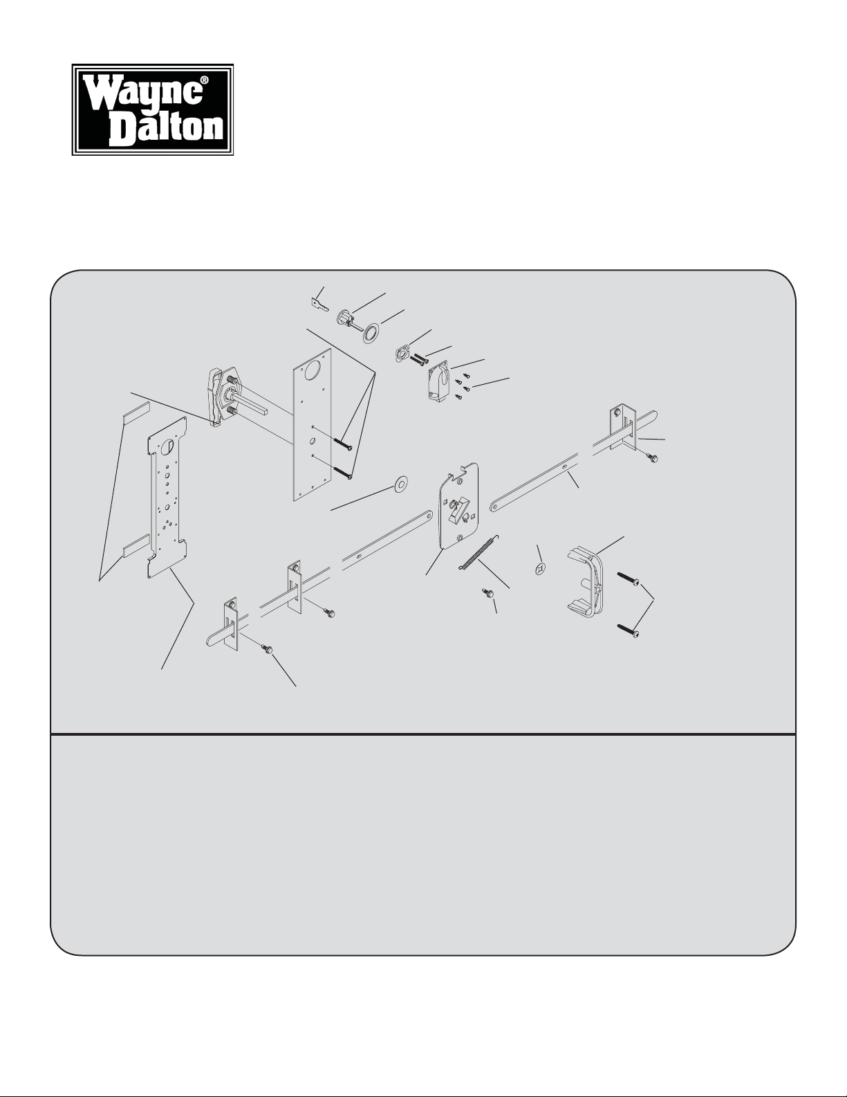
PHILLIPS HEAD MACHINE SCREWS
(2) 1” (9100) #306564
(2) 1-1/4” (9600/8300 & WOOD)#306565
(2) 1-1/2” (9900/9700) #306566
(2) 1-3/4” (8000/PR9000/8500) #306567
OUTSIDE HANDLE
#255544
3/8”X 1” USS WASHER
#100264
(2) KEYS*
RIM CYLINDER*
TRIM RING*
INSIDE LOCK PLATE*
*PART OF #316860 RIM CYLINDER LOCK KIT
(2) #12 PAN HEAD SCREWS*
NIGHT LATCH ASSEMBLY*
(4) #8 X 1/2” PAN HEAD SCREWS*
LOCK BAR GUIDE
(2/4) #254799
LOCK BAR
RETAINER NUT
#100280
INSIDE DOOR
HANDLE #128563
(2) FOAM TAPE
(9100/9600/9900)
3/4” X 2-1/2”
#306653
UNIVERSAL LOCK STILE
(9000 ONLY)
#261964
RELEASE DISK
#320284
1/4-20 X 11/16”
SELF DRILLING SCREWS
(2 PER GUIDE)#300723
Required Tools
(1) Electric Drill
(1) 1/8” Drill Bit
(1) 3/4” Dia. Hole Saw
(1) 1-1/4” Dia. Hole Saw
(1) 7/16” 6 Point Nut Driver
(1) 7/16” Wrench Or Socket
(1) Pliers/Wire Cutter
(1) Phillips Screw Driver
(1) Standard Screw Driver
(1) Center Punch
SPRING
#102834
1/4-20 X 11/16”
SELF DRILLING SCREW
#300723
1/4-14 X 1”
LAG SCREWS
OR
(WOOD DOORS ONLY)
#107584
1/4-20 X 1-3/4”
SELF TAPPING
SCREWS
(2)#129023
Important Notice!
REFER TO THE DOOR MODEL INSTALLATION INSTRUCTIONS MANUAL FOR
IMPORTANT SAFETY NOTICES.
© Copyright 2007 Wayne-Dalton Corp. Rev5 07/03/2007
Part No: 307899
Page 2
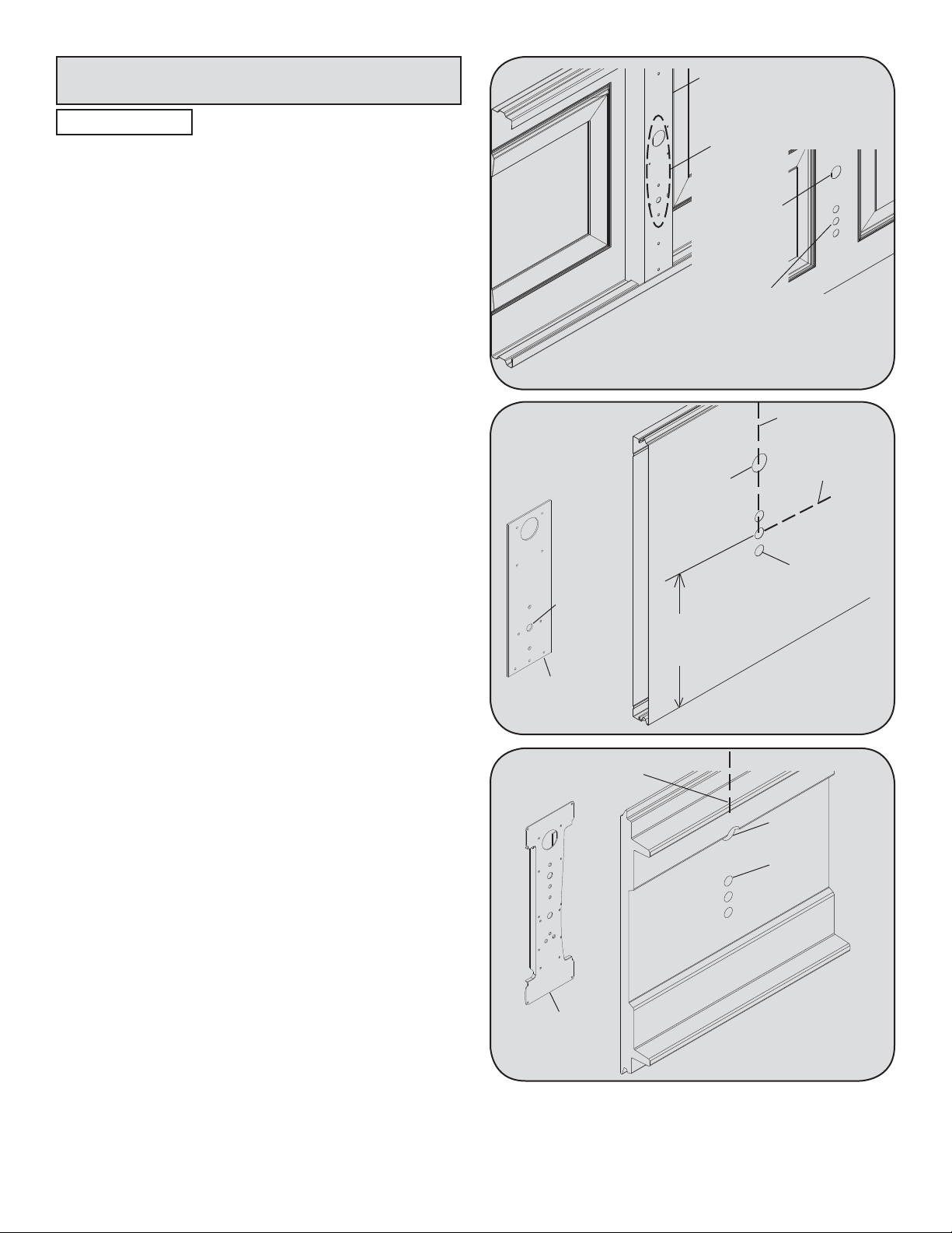
Step 1: Installing the ECR Lock
CENTER STILE
CAUTION
DO NOT DRILL LOCK SECTION
OR INSTALL LOCK ON DOORS WITH OPENERS.
THE DOOR AND/ OR OPENER MAY BE DAMAGED IF THE OPENER IS USED WHILE THE
DOOR IS LOCKED.
NOTE: Common practice for doors with the odd
number of raised panels is to mount the lock towards
the right side of the section when looking out.
IMPORTANT: Remove all burrs from the drilled
holes before installing the lock to the section.
8000/8100/8200/PR9000 & PR9050 Series doors (see
Fig.1), place the lock section face down on (2) padded
sawhorses for a single car door or (3) padded sawhorses
for a double car door. locate the (4) hole pattern in the
center stile of the lock section. Use the (4) holes as a
template to drill (4) 1/8” holes through the section. Flip
the section over, face up. With the section face up, enlarge the (3) bottom holes to 3/4” diameter and the top
hole to 1-1/4” diameter, pay close attention not to drill
completely through the section into the center stile.
NOTE: Do not drill through or enlarge holes in the
center stile.
8300/8500/9700 Series & Wood doors (see Fig.2), place
the lock section face up on (2) padded sawhorses for a
single car door or (3) padded sawhorses for a double
car door. Locate the middle of the center stile, measure
the distance from the end of the section to the middle of
the center stile. Turn the section face down, transfer the
measurement and mark a light vertical line, then mark a
horizontal line at half the section height. Align the 7/16”
diameter hole of the lock backup plate at the intersection
point of the horizontal and vertical marks, use the lock
backup plate as a template to mark the (4) holes, remove
the lock backup plate and drill the (3) bottom holes to
3/4” diameter and the top hole to 1-1/4” diameter, drilling
all (4) holes completely through the section.
FACE DOWN
7/16” DIA.
HOLE
LOCK BACKUP
PLATE
VERTICAL
LINE
(4)PRE-PUNCHED
HOLES
(1) 1-1/4” DIA.
HOLE
(3) 3/4” DIA.
HOLES
Fig. 1
(1) 1-1/4” DIA.
HOLE
1/2 THE
SECTION
HEIGHT
Fig. 2
FACE UP
VERTICAL
LINE
HORIZONTAL
LINE
(3) 3/4”DIA.
HOLES
FACE DOWN
(1) 1-1/4” DIA.
HOLE
(3) 3/4” DIA.
HOLES
9000 Series doors (see Fig.3), place the lock section
face up on (2) padded sawhorses for a single car door or
LOCK STILE
FACE DOWN
(3) padded sawhorses for a double car door. Locate the
middle of the center stile, measure the distance from the
Fig. 3
end of the section to the middle of the center stile. Turn
the section face down, transfer the measurement and mark a light vertical line. Align the center of the lock stile with
vertical mark, use the lock stile as a template to mark the (4) holes, remove the lock stile and drill the (3) bottom
holes to 3/4” diameter and the top hole to 1-1/4” diameter, drilling all (4) holes completely through the section.
2
Page 3

Step 2: Outside Lock Handle Assembly
8000/PR9000 & PR9050 Series doors (see Fig. 4),
align the outside handle assembly with the handle pointing towards the fl oor and insert the assembly through
the previously drilled 3/4” diameter holes in the section.
Secure the outside lock handle to the section with (2)
#10 phillips head screws.
9000 Series & Wood doors (see Fig. 5), align the outside handle assembly with the handle pointing towards
the fl oor and insert the assembly through the previously
drilled 3/4” diameter holes in the section. With the
outside lock placed in the section, place the center lock
stile over the shank of the outside lock handle, secure
the center lock stile with foam tape (8300/8500/9700
Series & Wood doors will use the lock backup plate
with no foam tape). Secure the outside lock handle to
the section by placing the (2) #10 phillips head machine
screws through the lock stile into the lock section.
Note: For 5140/9400 series doors, seal the v-groove
with a bead of clear silicone caulk.
OUTSIDE
HANDLE
3/4” DIA.
HOLES
3/4” DIA.
HOLES
OUTSIDE
HANDLE
HANDLE
SHANK
Fig. 4
FOAM TAPE
Fig. 5
#10 PHILLIPS
HEAD SCREWS
HANDLE
SHANK
LOCK
STILE
#10 PHILLIPS
HEAD SCREWS
Step 3: Inside Handle/ Lock Assembly
All 8000/9000 Series & Wood doors (see Fig.6-8),
hold the disk with the large notch of the release disk
pointing up. Using 1/4 - 20 carriage bolts and nylon
locking nuts, fasten lockbars to disk. Do not overtighten
nuts, bars must be free to rotate. (see Fig. 6).
First place the 3/8” x 1” USS Washer over the square
steel shank. Hold the handle which is pointing towards
the fl oor with one hand and place the disk over the
square steel shank of the outside handle. Push the
retainer nut onto the shank until the freeplay in the
assembly is taken up. Operate the lock to make sure it
functions properly. If the lock operates too hard, loosen
the retainer nut slightly.
Place the inside handle over the extruded holes in the
release disk (see Fig.8). Secure the handle with (2)
1/4-20 x 1-3/4” self tapping screws. Insert the rim
cylinder through the trim ring and into the section
with the teeth side of the key pointing away from the
outside handle.
PLACE 2nd LOCKBAR
1/4 - 20 CARRIAGE
BOLTS
1/4 - 20 NYLON
LOCKING NUTS
RELEASE DISK
LARGE NOTCH “UP”
PLACE 1st LOCKBAR
Fig. 6
SHANK
(OUTSIDE HANDLE)
RELEASE DISK
RETAINER
NUT
3/8” x 1” USS Washer
Fig. 7
3
Page 4

Step 3 : Continued
RIM CYLINDER
TRIM RING
Place the lock plate over the 1-1/4”diameter center
stile hole and fasten with (2) #12 pan head screws into
the rim cylinder. In addition, align the night latch slide
with the notch in the top of the release disk. Fasten the
night latch to the center stile with (4) #8 x 1/2” pan
head screws.
NOTE: Rotate the inside handle clockwise and tape
the lockbar to the section on both sides. Follow the
Main Installation Instructions Manual to install the
remaining door sections and track. After the sections
and track are installed, continue with Step 4.
RELEASE
DISK
EXTRUDED HOLES
IN RELEASE DISK
Fig. 8
LOCK PLATE
(2) #12 PAN
HEAD SCREWS
NIGHT LATCH
(4) #8 X 1/2”
PAN HEAD
SCREWS
(2) 1/4-20 X 1-3/4”
SELF TAPPING
SCREWS
INSIDE HANDLE
Step 4 : Installing The Lockbar Guides
Remove the tape attaching the lockbars to the section. Using slot #2, slide the required number of lockbar guides
over the lockbars with the mounting fl ange towards the center of the section. Lockbars 5’ or less require (1) guide
each and over 5’ require (2) guides each. Position, as level as possible, the ends of the lockbars into the square
slots of the vertical track. Turn the inside handle counterclockwise until the notch in the release disk aligns with the
slide of the night latch. Turn the key in the night latch to secure the lock assembly. Verify the lockbar ends engage
the vertical track slots. Position the lockbar guides at the end of the section, 1/8” back from the edge. Attach the
lockbar guide to the end stile with (2) 1/4-20 x 11/16” self drilling screws each (Wood doors use 1/4-20 x 1” lag
screws). For lockbars over 5’, position the second lockbar guide in the middle of the lockbar and secure the guide
with (2) 1/4-20 x 11/16” self tapping screws each (Wood doors use 1/4-20 x 1” lag
screws). Unlock the night latch and turn the inside handle clockwise. Hook the open
loop of the release spring into the slot of the right lockbar. Insert the 1/4-20 x 11/16”
self drilling screw through the closed loop of the release spring and secure it into
the lock backup plate hole below the lock assembly. Operate the lock several times
to make sure the lockbars move in and out of the vertical track smoothly. Adjust the
lockbar guides up or down, if necessary.
SECOND LOCKBAR GUIDE
REQUIRED FOR LOCKBARS
OVER 5’ IN LENGTH.
(9100 SERIES WILL USE EXTRA
STILES AND 1/2” SCREWS).
VERTICAL TRACK LOCKBAR SLOTS - USE THE
SLOT THAT WILL LEVEL
THE LOCKBAR THE
BEST
STRIKER
PLATE
“SLIDE” OF
NIGHT LATCH
SLOT #1
SLOT #2
CENTER STILE
1/8” OFFSET FROM
EDGE OF DOOR
END STILE
INSIDE
HANDLE
LOCKBAR
END STILE
LOCKBAR
GUIDE (UPSIDE
DOWN)
LOCKBAR
THROUGH
END STILE
(2)1/4-20 X 11/16”
SELF DRILLING SCREWS
9900 SERIES ONLY
LOCKBAR GUIDE
(MOUNTING FLANGE
TOWARDS CENTER)
1/4-20 X 11/16”
SELF DRILLING SCREWS
(2 PER GUIDE)
(WOOD DOORS USE
1” LAG SCREWS)
(2) 1/4”-20X9/16”TRACK
BOLTS
9700 SERIES ONLY
“NOTCH” OF
RELEASE DISK
RELEASE SPRING
1/4-20 X 11/16”
SELF DRILLING SCREWS
4
 Loading...