

Page 1

S T E E L S E C T I O N A L D O O R S
2411
W A Y N E - D A L T O N C O M M E R C I A L D O O R S Y S T E M S
2411
STEEL SECTIONAL DOORS
STRONG,VISUALLY APPEALING DOORS FOR MODERATE
COMMERCIAL APPLICATIONS
The Wayne-Dalton 2411 steel sectional door, available in a variety
of sizes, is an excellent value. Featuring nominal 24-gauge ribbed
steel sections, the 2411 is available with a number of lite and
insulation options.
• NOMINAL 24-GAUGE STEEL
CONSTRUCTION
• STANDARD SIZES UP TO
20'2"WIDE & 16'1"HIGH
• VALUE PRICED CHOICE
• DESIGNED FOR MODERATE
COMMERICAL APPLICATIONS
Page 2
SECTIONAL DOOR SYSTEMS
MODEL 2411
The Wayne-Dalton 2411 Steel Sectional Door is
designed to provide commercial strength at a
very competitive price. The embossed exterior
skin features a stucco finish to enhance the
building’s appearance, while “C”-shaped vertical
stiles on the door’s interior provide added
strength and allow quick, secure hinge
attachment. End stiles wrap around the exterior
of each section to protect the section face from
wear caused by the door jambs.
Materials & Construction
Wayne-Dalton’s 2411 features nominal 24-gauge
ribbed steel sections with vertical stiles attached
to the interior. These 20-gauge stiles are
securely attached with No. 8 screws and
adhesive and have prelocated, extruded holes
for hinge attachment. The exterior ribbing
consists of two deep and four shallow ribs in
each section, making it ideal for moderate use.
The bottom section features a vinyl bulb-shaped
astragal, held by a roll-formed, hot-dipped
galvanized steel retainer.
Additional options include top head seal, joint
seals and jamb seals. Optional insulation,
consisting of 1
covered with .015" minimum embossed
pre-painted white steel provides an R-value of
up to 7.64 and a U-value as low as 0.13. Lite
options include insulated or non-insulated
factory-installed vision lites or aluminum fullview sections for maximum visibility.
Contact Wayne-Dalton for additional sizes and
colors.
Color Options
9
/16" expanded polystyrene and
Operation Options
• Chain Hoist Operation
• Motor Operation
Performance Options
• High Cycle Spring (25K, 50K,100K)
• 3"Track Option
• Solid Shafts
• PerimeterWeatherseal
• Insulation
Window Options
Safety Options
• Broken Cable Devices
• Safety Edges
• Safety Photo Eyes
Special Application Options
• SpecialTrack Designs
• Mullions
Brown Embossed
Stucco Finish
White Embossed
Stucco Finish
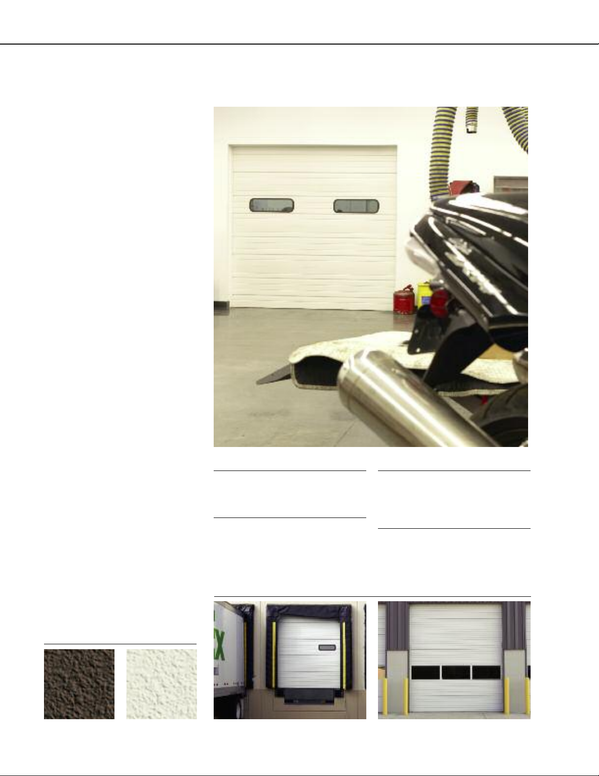
Vision Lites allow for visibility while
maintaining security
www.wayne-dalton.com/commercial
Aluminum full view sections allow for maximum
natural light and visibility
Page 3

STANDARD SIZES UP TO:
20' 2" WIDE & 16' 1" HIGH
NOMINAL 24-GAUGE STEEL SECTIONS
WINDLOAD:
MEET OR EXCEED
ANSI/DASMA 102-2003
IN ACCORDANCE WITH
ASTM E-330-70.
BEST APPLICATIONS:
Where usage requirements are moderate.
General Operating Clearances
Headroom*** Sideroom** Depth Into Room Center Line of Springs
Type 2" track 3" track 2" track 3" track 2" & 3" track 2" track 3" track
Standard Lift Manual12"R 121⁄2-17" NA Opening Height +12" NA
Standard Lift Manual15"R 141⁄2-20" 151⁄2-21" Opening Height +13" Opening Height +14"
Standard Lift Motor Oper. 12"R 15-191⁄2" NA 41⁄2"5
Standard Lift Motor Oper. 15"R 15-191⁄2" 18-231⁄2" Opening Height +13" Opening Height +14"
High Lift Manual
High Lift Motor Oper. 24" One Side
Vertical Lift Manual 12"R 41⁄2"5
Vertical Lift Motor Oper. 12"R 24" One Side
Low Headroom Manual* 6-141⁄2" 6-141⁄2" Opening Height +20" - 26"
Low Headroom Motor Oper.* 81⁄2-17" 81⁄2-17" Opening Height +66"
Door Height
+12"
Door Height
+20"
6" 9"
Opening Height +18"
1
⁄2" Opening Height +12" NA
Opening Height +66"
Opening Height – Lift +30"
1
⁄2"
Opening Height +18"
Opening Height
1
⁄2"
+Lift +6
Double Door Height
Opening Height
+Lift +7
+13"
Does Not Apply
1
⁄2"
Panel/Section Selection Guide
Door Section and Lite Selection Door Height and Section Selection
DoorWidth No.Panels Max. No.Windows Door Height No.Sections
Up to 9'2" 22Up thru 8'1" 4
9'3" to 12'2" 338'2" thru 10'1" 5
12'3" to 16'2" 4410'2" thru 12'1" 6
16'3" to 19'2" 5512'2" thru 14'1" 7
19'3" to 20'2" 6714'2" thru 16'1" 8
For Larger Sizes – See Model 2415
Track Selection Guide
Standard Lift High Lift
(break-away is
standard, straight
incline is available)
Roof Pitch
(standard or high lift)
*Note: Rear mount torsion requirements shown on chart.See
drawings for front mount torsion clearances.
**Note: 8” sideroom required,one sidefor doors having chain
hoist. 24" side room required,one side for doors having
jackshaft operators.
***Note: Clear headroom is based on cable size so please contact
factory for specific headroom for your door.
Vertical Lift Low Headroom
(rear mount torsion)
Low Headroom
(front mount torsion)
www.wayne-dalton.com/commercial
Page 4

SECTIONAL DOOR SYSTEMS
MODEL 2411
Note to specifiers: Words in parentheses indicate frequently specified and highly recommended options.
PART I – GENERAL
1.01 Section Includes
A. Sectional overhead doors [manually] [motor]
operated with accessories and components.
1.02 Related Work
A. Opening preparation,miscellaneous or structural
steel work,access panelsfinish or field painting are in
the scope of work of other trades and divisions of
these specifications.
1.03 Reference Standards
A. ANSI/DASMA 102 – American National
Standards Institute [A216.1] Specifications for
sectional overhead doors published by Door &
Access Systems ManufacturersAssociation
International in bulletin102-1990.
B. ASTMA123 – Zinc [hot-dipped galvanized]
coatings on iron and steel products.
C. ASTM A216 – Specifications for sectional
overhead type doors.
D. ASTM A229 – Steel wire, oil-tempered for
mechanical springs.
E. ASTM A-653-94 – Steel sheet, zinc-coated
[galvanized] by the hot-dipped process,
commercial quality.
F. ASTM E330 – Structural performance of
exterior windows,curtain walls,and doors by
uniform static air pressure difference.
G. ASTM E413-87 – Sound transmission class.
Acoustical performance value = 24 per. J.
H. ASTM E1332-90 – Outdoor-indoor
transmission class. Acoustical performance value = 20.
1.04 Quality Assurance
A. Sectional overhead doors and all accessories and
components required for complete and secure
installations shall be manufactured as a system from
one manufacturer.
1.05 Systems Description
A. Sectional Overhead Door:Type:
Model 2411
B. Mounting:Continuous angle mounting for [steel]
[wood] jambs [bracketmounting for wood jambs]
C. Operation:[manual push-up][chain hoist] [motor]
[motor withchain hoist]
D. Material:Galvanized steel withpolyester finish paint
E. Insulation:Optional [polystyrene] [polyurethane]
1.06 Submittals
A. Shop Drawings:Clearly indicate the following:
1. Design and installation details to withstand
standard windload.
2. All details required for complete operation
and installation.
3. Hardware locations.
4. Type of metal and finish for door sections.
5. Finish for miscellaneous components and
accessories.
B. Product Data:Indicating manufacturer’s product
data,andinstallation instructions.
1.07 Delivery, Handling,Storage
A. Deliver products in manufacturer’s original
containers,dry, undamaged,seals and labels intact.
B. Store and protect products in accordance with
manufacturer’s recommendations.
1.08 Warranty
A. Standard manufacturer’sTENYEAR warranty against
cracking, splitting or deterioration due to rust-through.
PART I I – PRODUCTS
2.01 Manufacturer
A. Wayne-Dalton or approved equal Model 2411
insulated sectional overhead doors of steel
construction complete as specified in this section and
as manufactured by Wayne-Dalton Corp.,
Mt.Hope,Ohio.
2.02 Materials
A. Door Sections:Shall be ofroll formed steel typewith
“c” shaped 20 ga.[intermediate and end stiles
construction] and calculated materials“R”- value of
7.64 [optional] in accordance with industry guidelines.
1. Exterior Skin:Structural quality, hot-dipped
galvanized steel, with embossed stuccofinish
nominal24 ga.with baked-on polyester primer and
[white][brown]polyester finish coats with
non-repeating random stucco texture and
2 deep and 4 shallowpinstripes.
2. Insulation:Cavity shall be filled withlaid-in-place
[polyurethane] [expanded polystyrene] and
covered with [vinyl] [ 0.022” minimum embossed
steel] heldin place with polymer clips.
B. Track:Track design shall be [standard lift] [high lift]
[vertical lift] [low headroom].Vertical mounting angles
shall be hot-dipped galvanized.Track size shall be [2"]
[3"].Vertical track shall be graduated to provide wedge
type weathertight closing with continuous angle
mounting for [steel] [wood] jambs,andshall be fully
adjustable to seal door at jambs [bracket mount for
wood].Horizontal track shall be reinforced with
continuous angle of adequate lengthand gauge to
minimize deflection.
Note: Horizontal track applies to standard lift,high lift, low
headroom and follow-the-roof designs only.
C. Hardware:Hinge and RollerAssembly:
1. Hinges and brackets shall be made from hotdipped,galvanized steel.
2. Track rollers shall be case-hardened inner
steel races with 10-ball [2"][3"] rollers.
3. All factory authorized attachments shall be
made at locations indicated.
D. Counterbalance:
1. Springs shall be torsion type,low-stress,helical
wound,oil-tempered spring wire to provide
minimum [10,000 standard] [25,000] [50,000]
[100,000] cycles of use,on continuous steel [solid].
2. Spring fittings and drums made of die cast,high
strength aluminum.
3. Pre-formed galvanized steel aircraft cableshall
provide a minimum of a 5:1safety factor.
2.03 Operation
A. Operation shall be [manual push-up] [chain
hoist] [motor] [motor with chain hoist].
Note: Manufacturer does not recommend chain
hoists or jack shaft operators on the following
track applications.
• 15" radius standard lift with roof pitch
less than2:12
• Hi-lift less than 24"
• Hi-lift between 12" – 23" withroof pitch
less than1:12
• Low headroom track
Specialchain hoist assemblies (usinga trolley rail)
are available for the above track systems.
2.04 Locks
A. Locks shall engage the right-hand vertical track and
utilize[aninterior side lock] [standard size rim
cylinder].
2.05 Weatherstripping
A. Doors shall be equippedwith vinylbulb shaped astragal
as standard on the bottom section. Optional joint,top.
head and jamb seal are available.
2.06 Glazing
A. Optional.
2.07 Windload
A. Windload – per DASMA 102-2003 and as required by
local codes.
PART III – EXECUTION
3.01 Installation
A. General:
1. Install doorsin accordance with manufacturer’s
instructions and standards.Installation shall be by an
authorizedWayne-Daltonrepresentative.
2. Verify that existingconditions are ready to receive
sectional overhead door work.
3. Beginning of sectional overhead door work means
acceptance of existing conditions.
B. Install door complete withnecessary hardware,jamb
and head mold strips,anchors,inserts,hangers,and
equipment supports in accordance with final shop
drawings,manufacturer’s instructions,and as specified
herein.
C. Fit,align and adjust sectional overhead door assemblies
level and plumb for smooth operation.
D. Upon completion of final installation,lubricate,test and
adjust doors to operate easily, free from warp,twist or
distortion and fitting for entire perimeter.
Note: Architect may consider providing a schedule when
more than one sectional overhead door or opening
type is required.
3.02 Materials (See note above.)
Specifications and technical information also available at www.arcat.com, SpecWizard™, and Sweets.com®.
Distributed By:
For technical information, visit:
www.wayne-dalton.com/commercial
© 2007 Wayne-Dalton Corp. • One Door Drive • Mt. Hope, Ohio 44660 • 800-764-1457
Mt. Hope, OH • Dalton, OH • Trail, OH • Pensacola, FL • Portland, OR
Printed in U.S.A.
Item #332542 Revised 9/2007
 Loading...