

Page 1
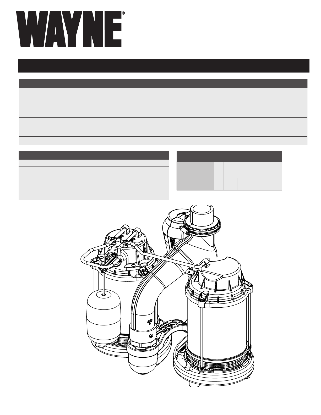
Submersible Sump Pump System
Please read and save these instructions. Read carefully before attempting to assemble, install,
operate or maintain the product described. Protect yourself and others by observing all safety
information. Failure to comply with instructions could result in personal injury and/or property
damage! Retain instructions for future reference.
Operating Instructions and Parts Manual WSS30Vn
SPECIFICATIONS AC SPECIFICATIONS DC SPECIFICATIONS
POWER SUPPLY REQUIREMENTS 120 V, 60 Hz 12 V, DC*
MOTOR Single Phase, Dielectric Oil Filled Permanent Magnet DC
POWER
CIRCUIT REQUIREMENTS 15 A (minimum) 15 A (minimum)
DIMENSIONS
ON LEVEL Approximately 9 in. 10-12 in.
OFF LEVEL
11 ½ in. high x 9 ¾ in. base 11 ½ in. high x 9 ¾ in. base
1/2 HP 100 Watts
Approximately 4 in. N/A
CONSTRUCTION AC DC
MOTOR HOUSING Coated Steel
VOLUTE
IMPELLER Glass Reinforced Thermoplastic
SHAFT Steel Stainless Steel
DISCHARGE 1-1/2 in. NPT
Cast Iron
PERFORMANCE GAL/HR
Model HP
WSS30Vn AC 1/2 5100 4500 3840 3060
WSS30Vn DC 12V 2700 2130 1500 720
* Battery not included. Wayne WSB1275 is
recommended
Discharge Head (Lift Distance)
0 ft 5 ft 10 ft 15 ft
© 2018, WAYNE/Scott Fetzer Company
Intended for Indoor Use Only
www.waynepumps.com
670001-001 F 07/19
Page 2
Operating Instructions and Parts Manual
SYSTEM DESCRIPTION
This product is fully assembled and pre-plumbed ½ HP primary &
12 Volt backup sump system. The pumps are designed for use in
residential basements to remove groundwater and prevent flooding.
The pumps are designed for clear water only. LED indicator lights
inform the howeowner of the charge status of the battery. Wayne
recommends the WSB1275, 75 AMP hr maintenance free battery
(sold seperately), to complete the sytem. Designed for 15 in. diameter
or larger sump basins. This system is intended for indoor use only.
Installation of this pump outdoors, unprotected from the weather,
may cause hazardous conditions and will void warranty. If using
outdoors, protect pump from direct weather elements such
as sun, rain, sleet, snow, and extreme temperature changes.
Water inside the pump may freeze, limiting its performance and
damaging the pump and pipes.
UNPACKING
Inspect this unit before it is used. Occasionally, products are damaged
during shipment. If the pump or components are damaged, return
the unit to the place of purchase for replacement, or call Customer
Support (800-237-0987).
SAFETY SIGNAL WORDS
This manual contains information that is very important to know and
understand. This information is provided for SAFETY and to PREVENT
EQUIPMENT PROBLEMS. To help recognize this information, observe
the following symbols.
IMPORTANT SAFETY INFORMATION
RISK OF ELECTRIC SHOCK. TO REDUCE THIS RISK,
OBSERVE THE FOLLOWING WARNINGS:
RISQUE DE CHOC ÉLECTRIQUE. POUR RÉDUIRE CE RISQUE,
TENIR COMPTE DES AVERTISSEMENTS SUIVANTS :
MAKE SURE THERE IS A PROPERLY GROUNDED RECEPTACLE
AVAILABLE. The AC pump & transformer are supplied with a
grounding conductor and grounding-type attachment plug. To
reduce the risk of electric shock, be certain that it is connected
only to a properly grounded, grounding-type receptacle.
S’ASSURER QU’UNE PRISE DE MISE À LA TERRE EST DISPONIBLE. Cette
pompe et le transformateur c.a. sont fournis avec un conducteur
et une fiche de type mise à la terre. Pour réduire le risque de choc
électrique, s’assurer qu’elle est branchée seulement à une prise de
courant correctement mise à la terre.
FOR ADDED SAFETY the receptacle must be protected with a ground
fault circuit interrupter (GFCI). All wiring must be performed by a
qualified licensed electrician and comply with the National Electric
Code and all applicable local codes and ordinances.
POUR PLUS DE SÉCURITÉ, la prise de courant doit être protégée par
un disjoncteur de fuite à la terre. Tout le câblage doit être effectué
par un électricien qualifié et être conforme au Code électrique
national et à tous les codes et règlements locaux applicables.
NEVER REMOVE THE GROUND PRONG from the plug or bypass the
grounding wires.
NE JAMAIS RETIRER LE CONNECTEUR DE MISE À LA TERRE de la prise
ou contourner les fils de mise à la terre.
Danger indicates an imminently hazardous
situation which, if NOT avoided, WILL result in death or serious injury.
La mentio ger indique une situation dangereuse
imminente qui, si elle n’est pas évitée, ENTRAÎNE la mort ou des blessures
graves.
Warning indicates a potentially hazardous situation
which, if NOT avoided, COULD result in death or serious injury.
La mention avertissement indique une situation
potentiellement dangereuse qui, si elle n’est pas évitée, risque d’entraîner
des lésions corporelles graves ou même la mort.
Caution indicates a potentially hazardous situation
which, if NOT avoided, MAY result in minor or moderate injury.
MISE EN GARDE
situation potentiellement dangereuse qui, si elle n’est pas évitée, pourrait
entraîner des blessures mineures ou modérées.
followed, MAY cause damage to equipment.
La mention mise en garde indique une
Notice indicates important information, that if NOT
THIS SYSTEM IS NOT DESIGNED TO HANDLE SALT WATER,
BRINE, LAUNDRY DISCHARGE, WATER SOFTENER, SEWAGE,
GREY WATER, OR ANY OTHER APPLICATION WHICH MAY
CONTAIN CAUSTIC CHEMICALS AND/OR FOREIGN MATERIALS.
PUMP AND/OR PROPERTY DAMAGE COULD OCCUR IF USED IN
THESE APPLICATIONS AND WILL VOID WARRANTY
DO NOT REMOVE POWER SUPPLY CORD and strain relief or connect
conduit directly to the pump.
NE PAS RETIRER LE CORDON D’ALIMENTATION ÉLECTRIQUE et le
réducteur de tension, ni connecter le conduit directement à la
pompe.
MAKE SURE THE POWER SUPPLY HAS A FUSE OR CIRCUIT BREAKER
rated to handle the current (amps) noted on the pump nameplate
or cord tag.
S’ASSURER QUE L’ALIMENTATION ÉLECTRIQUE EST MUNIE D’UN
FUSIBLE OU D’UN DISJONCTEUR d’une valeur nominale appropriée
pour supporter l’intensité du courant (ampérage) indiquée sur la
plaque signalétique ou l’étiquette du cordon de la pompe.
2
www.waynepumps.com
Page 3
IMPORTANT SAFETY INFORMATION (CONT’D)
ALWAYS DISCONNECT THE PUMP from power supply before installing,
servicing or making any adjustments.
TOUJOURS METTRE LA POMPE HORS TENSION avant de procéder à
l’installation, à l’entretien ou à des réglages.
DO NOT WALK on the floor when water is present until all power is
turned off. If the electric panel is in the basement, call an electrician.
NE PAS MARCHER sur un sol mouillé avant que l’alimentation
générale ne soit coupée. Si le tableau électrique est en sous-sol,
appeler un électricien.
WSS30VnOperating Instructions and Parts Manual
DO NOT USE AN EXTENSION CORD OR SURGE PROTECTOR.
Extension cords and/or surge protectors could present a safety
hazard if not sized properly, become damaged or the connection
falls into the sump. If receptacle is not within reach of the pump’s
power cord, contact a qualified licensed electrician to install a new
receptacle.
NEVER HANDLE A PUMP or motor with wet hands or when standing
on a wet or damp floor while the pump is plugged into the power
supply.
NE JAMAIS MANIPULER UNE POMPE ou un moteur de pompe avec
les mains mouillées ou debout dans l’eau ou sur une surface
humide.
RISK OF ELECTRIC SHOCK. This system has not been investigated for
use in swimming pool and marine areas.
RISQUE DE CHOC ÉLECTRIQUE. Ce système n’a pas fait l’objet de
vérification pour une utilisation dans les piscines ou les aires
marines.
DO NOT USE TO PUMP FLAMMABLE OR EXPLOSIVE FLUIDS such as
gasoline, fuel oil, kerosene, etc. Do not use in a flammable and/
or explosive atmosphere. System should only be used to pump
clear water. Personal injury and/or property damage could result
and void warranty.
NE PAS UTILISER POUR POMPER DES FLUIDES INFLAMMABLES OU
EXPLOSIFS tels que l’essence, le mazout, le kérosène, etc. Ne pas
l’utiliser dans un environnement inflammable et/ou explosif. La
pompe DOIT être utilisée uniquement pour pomper de l’eau claire.
Des blessures corporelles et/ou des dégâts matériels pourraient en
résulter et annuler la garantie.
PUMPS ARE NOT DESIGNED TO TRANSFER WATER INTENDED FOR
DRINKING. Do not use the pumps for moving water that will be
used for portable/drinking water. Pumps should only be used in
applications for which it is designed.
LES POMPES NE SONT PAS CONÇUES POUR L’ACHEMINEMENT
D’EAU DESTINÉE À LA CONSOMMATION. Ne pas utiliser la pompe
pour transporter de l’eau qui sera utilisée comme de l’eau
potable/destinée à la consommation. La pompe doit être utilisée
uniquement dans les applications pour lesquelles elle est conçue.
NE PAS UTILISER DE RALLONGE NI DE PROTECTEUR DE
SURTENSION. Les rallonges et/ou les protecteurs de surtension
peuvent présenter un danger pour la sécurité s’ils ne sont
pas correctement calibrés, s’ils sont endommagés ou si le
raccordement tombe dans le puisard. Si la prise n’est pas à portée
du cordon d’alimentation de la pompe, contacter un électricien
qualifié pour installer une nouvelle prise.
TO REDUCE THE RISK OF HAZARDS THAT CAN CAUSE
INJURY OR PROPERTY DAMAGE, OBSERVE THE
FOLLOWING WARNINGS:
POUR RÉDUIRE LE RISQUE DE DANGERS POUVANT
CAUSER DES BLESSURES OU DES DÉGÂTS MATÉRIELS,
RESPECTER LES MISES EN GARDE SUIVANTES :
IT IS THE INSTALLER’S RESPONSIBILITY TO MAKE SURE THE PUMPS
AUTOMATIC SWITCHES ARE ABLE TO OPERATE WITHOUT ANY
OBSTRUCTIONS WITHIN THE BASIN. It is recommended that the
installer test and observe the operation for several cycles after
installation.
IL EST DE LA RESPONSABILITÉ DE L’INSTALLATEUR DE S’ASSURER
QUE LES INTERRUPTEURS AUTOMATIQUES DE POMPE PEUVENT
FONCTIONNER SANS AUCUN BLOCAGE À L’INTÉRIEUR DE LA CUVE. Il est
recommandé que l’installateur teste et observe le fonctionnement
de la pompe pendant plusieurs cycles après l’installation.
IT IS REQUIRED TO USE RIGID PIPING AND FITTINGS to secure the
system in the basin and reduce pump movement. Pump movement
can prevent the switch from operating correctly. Do not use flexible
hose.
IL EST NÉCESSAIRE D’UTILISER DES TUYAUX ET DES RACCORDS
RIGIDES pour fixer la pompe dans la cuve et réduire les mouvements
de la pompe. Les mouvements de la pompe peuvent empêcher
l’interrupteur de fonctionner correctement. Ne pas utiliser de
tuyaux flexibles.
www.waynepumps.com
DO NOT INSTALL OR OPERATE THE PUMPS IF THEY HAVE BEEN
DAMAGED IN ANY WAY.
NE PAS INSTALLER OU FAIRE FONCTIONNER LA POMPE SI ELLE A ÉTÉ
ENDOMMAGÉE DE QUELQUE MANIÈRE QUE CE SOIT.
DO NOT LIFT OR CARRY THE SYSTEM BY THE POWER CORDS.
NE PAS SOULEVER OU PORTER LE SYSTÈME PAR LE CORDON
D’ALIMENTATION.
3
Page 4
AVERTISSEMENT
Operating Instructions and Parts Manual
IMPORTANT SAFETY INFORMATION (CONT’D)
DO NOT USE THIS SYSTEM IN MUD, SAND, CEMENT, OIL CHEMICALS,
GREY WATER, OR ANY OTHER WATER THAT IS NOT CLEAR GROUND
WATER.
NE PAS UTILISER CE SYSTÈME DANS LA BOUE, LE SABLE, LE CIMENT,
LES PRODUITS CHIMIQUES À L’HUILE, DE L’EAU GRISÂTRE OU TOUTE
AUTRE EAU QUI N’EST PAS DE L’EAU CLAIRE SOUTERRAINE.
DO NOT USE SUMP PUMPS TO HANDLE RAW SEWAGE.
NE PAS UTILISER DE POMPES DE PUISARD POUR POMPER LES
EFFLUENTS.
This product can expose you to chemicals, including DEHP, which
is known to the State of California to cause cancer, birth defects
and reproductive harm. For more information, go to www.
P65Warnings.ca.gov.
Ce produit peutvous exposer à des produits chimiques,
notamment du DOP, reconnus par l’État de Californie comme
étant cancérigènes et à l’origine d’anomalies congénitales et de
problèmes de l’appareil reproductif. Pour plus de renseignements,
visiter le site www.P65Warnings.ca.gov.
BATTERY INFORMATION
The system is designed to operate most efficiently with an AGM
battery. A WAYNE WSB1275 is recommended. The oversize battery
case (included) will accommodate a 12 Volt AGM battery (up to a
group 27-frame size).
Be certain that the area around the battery is well
ventilated. Before servicing the battery, blow away gasses by waving a piece of
cardboard near the batteries.
AVIS
ventilée. Avant d’effectuer l’entretien des batteries, évacuer les gaz en agitant un
morceau de carton près des batteries.
while charging. Sparks can ignite the gas in an enclosed space. Wear safetly goggles
when connecting battery. Battery connections should be made in a well ventilated
area.
pendant le chargement. Les étincelles peuvent enflammer le gaz dans un espace
clos. Porter des lunettes de sécurité pour brancher les batteries. Les connexions de la
batterie doivent être effectuées dans un endroit bien ventilé.
dangerous. Before making the connections or servicing the batteries, read and follow
instructions on all applicable instruction manuals. To reduce the risk of battery
explosion, follow the instructions in this manual and those published by the battery
manufacturer, as well as those of any other equipment used in the surrounding area.
S’assurer que la zone autour des batteries est bien
Dangerous hydrogen gas can be released from the battery
De l’hydrogène dangereux peut s’échapper des batteries
Working in the vicinity of a lead acid battery can be
VERTICAL FLOAT SWITCH This float is not adjustable. Any
modifications or alterations will void the warranty and/or
cause premature failure of the pump, which could lead
to property damage.
INTERRUPTEUR À FLOTTEUR VERTICAL. Ce flotteur n’est
pas réglable. Toute modification ou altération peut
entraîner une défaillance prématurée de la pompe avec
pour conséquences des risques de dégâts matériels.
Ces modifications ou altérations annuleront la garantie
du matériel.
An assistant should be present or close enough to come
to your aid in the event of an emergency. Have a reliable source of fresh water and
soap nearby in case batttery acid contacts skin or eyes.
Wear eye and clothing protection when working around
lead acid batteries. Avoid touching your eyes when working around lead acid
batteries.
If battery acid contacts your eye(s), flush with cold
running water for 10 minutes and seek immediate medical attention. If acid contacts
your skin or clothing, wash immediately with soap and water.
Si de l’acide de batterie entre en contact avec les
yeux, les rincer avec de l’eau courante froide pendant 10 minutes et consulter
immédiatement un médecin. Si l’acide entre en contact avec la peau ou les
vêtements, les laver immédiatement avec de l’eau et du savon.
Never smoke or allow a spark or flame in the vicinity of
the battery.
Ne jamais fumer ou laisser une étincelle ou une flamme
près de la batterie.
Avoid dropping metal tools on the battery posts because
they may spark or short-circuit the system or battery, causing an explosion.
Éviter de faire tomber des objets en métal sur les bornes
de la batterie: cela pourrait créer des étincelles ou des courts-circuits du système ou
de la batterie, provoquant une explosion.
4
www.waynepumps.com
Page 5

Operating Instructions and Parts Manual
WSS30Vn
INSTALLATION
INSTALLATION OF THIS UNIT MAY TAKE
SEVERAL HOURS. BEFORE DISABLING YOUR MAIN PUMP, HAVE READY AN
APPROPRIATE MEANS OF EVACUATING THE SUMP.
1. Turn power to main pump off.
2. Pump must be installed using 1-1/4 in. or 1-1/2 in. rigid
PVC piping. Do not use flexible hose.
Figure 1: Submersible Sump System
1
13
1
9
8
7
10
4
2
3
12
11
14
MINIMUM
BASIN
DEPTH
(22 IN.)
AC
DC
5
ON
LEVEL
LEVEL
9"
10" NA
OFF
4"
6
15 IN. DIAMETER MIN.
15
4. Clean the basin/pit of all debris.
5. If using a basin, place the system directly on the bottom of
the basin.To prevent damage set the system on a solid, level
surface. Do not place units directly on clay, earth, gravel or
sand. A brick or blocks can be installed under the pumps to
provide a solid base.
6. Position system so the float switch is away from the inlet
so float switch is clear from incoming water. Verify the float
has at least 1 in. clearance to the side wall of the basin and
is free to move throughout its travel.
7. Install discharge plumbing according to local, regional
and state codes. Rigid PVC pipe is required. Do not
use flexible hose in a permanent application. A 1-1/2
PVC schedule 40 coupling is required on diverter valve
discharge. Do not use schedule 20 couplings or drainage
fittings.
8. Install removable check valve (8) (Wayne Part Number:
57028-001) positioned just above the basin to allow easy
removal of the system for cleaning
and service. Note: A check valve is required to prevent
back-flow.
9. Install a gate valve or ball valve if required by local, regional
or state code.
10. Connect pump power supply cord to a ground fault circuit
interrupter (GFCI) outlet (1).
1. GFCI GROUNDED OUTLETS
2. AC PUMP POWER CORD
3. DC PUMP POWER CORD
4. DISCHARGE PIPE
5. AC PUMP (Primary)
6. DC PUMP (Secondary)
7. VENT PIPE
8. REMOVABLE CHECK VALVE
THIS INSTALLATION MUST BE IN ACCORDANCE WITH
THE NATIONAL ELECTRIC CODE AND ALL APPLICABLE LOCAL CODES AND
ORDINANCES.
3. Use a basin (purchased seperately) or pit that is large enough
to accommodate the system. The minimum requirements for
the sump system are shown in Figure 1.
9. GASKET/BASIN LID
10. BATTERY BOX CONTROLLER
11. DC FLOAT SWITCH
12. DC FLOAT SWITCH CORD
13. TRANSFORMER
14. 1½” PVC SCHEDULE 40
COUPLING
15. DIVERTER VALVE
www.waynepumps.com
5
Page 6

Operating Instructions and Parts Manual
AC PUMP CHECK
1. Fill the basin/pit with water. The pump will start when the
water level has reached the float switch-on level.
2. The pump will stop when the water level has reached the
switch-off level.
3. Verify the switch is operating without any obstruction from
the pump, piping and basin.
4. Fill the basin/pit with water again. While the system is
draining the basin/pit, verify the discharge pipe is carrying
the water to a point at least 3 ft. away from the foundation.
If the discharge line is exposed to freezing temperatures,
the pipe must be positioned in a downward slope away
from the foundation so any remaining water will drain away
and not freeze.
CONTROL BOX INSTALLATION
FLOOR JOIST
TRANSFORMER
REQUIRED
CHECK VALVE
(SEE STEP 3 & 7)
45º elbow
SLOPE
PIPE
DOWN
"Y"
CONNECTOR
REQUIRED
CHECK VALVE
(SEE STEP 3)
RIGID
PVC
PIPE
1. Place battery in box, attach red cable to positive battery
post and black cable to negative battery post.
If cables are reversed, damage to the control box or
battery will result, and void warranty.
MISE EN GARDE
contrôle ou la batterie pourrait être endommagée et la garantie annulée.
Si les câbles sont inversés, la boîte de
2. Plug the float pump system and transformer into the
appropriate connectors. The connections are all unique
and cannot be interchanged.
BATTERY BOX
FLOAT SWITCH
PRIMARY AC PUMPBACKUP DC PUMP
Figure 2 - Method 2
3. Put lid on box, and place the battery within six feet of the
sump and a 115 VAC separately fused outlet. The
outlet must be protected by a ground fault circuit
interrupter (GFCI) The area must also be clean, dry and
well ventilated.
Do not allow battery box to get wet, or expose it to
moisture. Electronics will be damaged and void warranty.
MISE EN GARDE
être mouillé ou exposé à l’humidité. Les appareils électroniques seront
endommagés et la garantie sera annulée.
Ne pas laisser le coffre de la batterie
BACK UP PUMP CHECK
1. Test system operation by filling the sump with water
while the main pump is unplugged. If the pump operates
properly, plug the transformer into the GFCI protected
outlet to begin charging the battery.
2. Protect electrical cord from sharp objects, hot surfaces,
oil and chemicals. Avoid kinking the cord.
3. Secure power supply cord to discharge pipe using cable or
zip ties to prevent possible switch entanglement.
6
www.waynepumps.com
Page 7

Operating Instructions and Parts Manual
WSS30Vn
OPERATION
Always disconnect the power source before
attempting to install, service, relocate or maintain the pump. Never touch
sump pump motor, water or discharge piping when pump is connected to
electrical power. Never handle a pump or pump motor with wet hands or
when standing on wet or damp surface or in water. Fatal electric shock
could occur.
Toujours débrancher le cordon d’alimentation
avant d’essayer d’installer, de réparer, de déplacer ou de faire l’entretien
de la pompe. Ne jamais toucher le moteur de la pompe de puisard, l’eau
ou les tuyaux d’évacuation lorsque la pompe est branchée à une source
d’alimentation électrique. Ne jamais manipuler une pompe ou le moteur
d’une pompe avec les mains humides, ou debout sur une surface mouillée
ou humide ou dans l’eau. Cela pourrait occasionner un choc électrique.
Risk of electrical shock! Use a gfci receptacle
to reduce the risk of fatal electric shock. Cutting the cord will void the
warranty and make the pump inoperable.
Risque de choc électrique! Utiliser une prise avec
disjoncteur de fuite à la terre pour réduire le risque de choc électrique.
Couper le cordon annulera la garantie et rendra la pompe inutilisable.
1. After installation, the backup pump will start
when the water level rises above the backup float switch.
Risk of electrical shock! Unplug main
ac pump and the transformer.
Risque de choc électrique!
Débrancher la pompe principale et le transformateur de
courant c.A.
a. After main pump and transformer are unplugged, a
power off alert tone will sound for 30 seconds.
b. Press and release the self test button to activate the back
up pump.
c. When the pump stops, read the charge indicator lights:
Green: Indicates the battery is fully charged.
Yellow: Indicates battery partially charged, still operable.
Red: Battery is completely discharged or defective.
Red blinking: Battery discharged below level where
pumping can occur. Motor is locked out by controller
until battery is sufficiently charged to run pump.
2. The control box has a DC charger designed to
shorten the recharging time of your battery, and to
prevent overcharging. In addition, the control box has
a time delay which keeps the pump from repeated,
short cycles when it shuts off. The time delay feature
will allow the pump to run 20-25 seconds after the
switch reaches the off position.
3. The control box contains multi-colored indicator
lights. When AC power is present, the lights will
indicate the charging state, and not reflect actual
battery voltage, particularly with a defective battery. In
order for the indicator light to provide an accurate
reading, steps “a” through “d” must be followed.
d. Plug in transformer and main AC pump.
When main AC power is out, and when pump has been
running, the lights will indicate battery status.
4. A chirping sound from the control box will accompany
the red light, indicating that the battery may require
attention or replacement. Voltage is only an indicator
of battery condition and may not reflect the true
condition of the battery. See maintenance for
instruction on assessing battery condition.
5. A single thirty (30) second tone will sound when
power to the system is interrupted and the power
failure light will illuminate. The unit will reset and the
light will go out automatically when power is
restored.
6. A three (3) second tone will sound every time
the
pump starts.
Secure the basin cover and gasket to the basin to
prevent debris from falling into the basin, prevent personal injury, and to
contain gases and/ or odors.
MISE EN GARDE
d’étanchéité à la cuve pour éviter que des débris ne tombent dedans,
prévenir les blessures corporelles et contenir les gaz et les odeurs
Fixer le couvercle de cuve et le joint
www.waynepumps.com
7
Page 8

Operating Instructions and Parts Manual
TROUBLESHOOTING WARNINGS
LET PUMP COOL FOR A MINIMUM OF 2 HOURS BEFORE
ATTEMPTING TO SERVICE. Submersible pumps contain oil that
become pressurized and hot under normal operating conditions.
LAISSER REFROIDIR LA POMPE PENDANT AU MOINS 2 HEURES
AVANT D’ESSAYER DE LA RÉPARER. Les pompes submersibles
contiennent de l’huile qui devient pressurisée et chaude dans des
conditions normales de fonctionnement.
1. Submersible pump models have permanently lubricated
bearings and require no additional lubrication.
2. Submersible pump contains dielectric oil for cooling.
Dielectric oil can be harmful to the environment. Follow
state environmental laws when disposing of pump.
3. The AC pump motor is equipped with automatic resetting
thermal protector and may restart unexpectedly. Protector
tripping is an indication of motor overloading as a result of
operating the pump at low heads, excessively high or low
voltage, inadequate wiring, incorrect motor conditions, or at
the end of its life.
AC ROUTINE SUMP MAINTENANCE
The pump system should be inspected 3-4 times per year for
movement or buildup of debris on the switch or float. Reposition system if it has moved. Remove any debris that could
interfere with the operation of the switches. Lack of proper
routine maintenance will void warranty.
• Make sure the system is plugged in to a working ground fault
circuit interrupter (GFCI) outlet and the cord is in good shape.
In damp areas, GFCI breakers may trip, effectively shutting off
the sump pump. Check in on your sump pump and reset the
GFCI if necessary. Replace pump if GFCI continues to trip.
• Ensure the system is upright. Vibrations during operation can
cause it to fall or tilt onto one side. This can jam the float so it
can’t activate the pump.
• Pour a bucket of water into the pit to make sure the AC
pump starts automatically and the water drains quickly once
the pump is on. If the pump doesn’t start, have it serviced or
replaced.
• Check the inlet screen and clear away any small stones or
debris.
8
www.waynepumps.com
Page 9

Operating Instructions and Parts Manual
AC TROUBLESHOOTING CHART
Symptoms Possible Cause(s) Suggested Remedies
Pump will not
start or run
1. Water level too low
2. Blown fuse or tripped circuit breaker
3. Low supply voltage
4. Motor
5. Switch
6. Inlet screen clogged
7. Switch obstruction
1. Water must be at the appropriate level to activate switch
2. If blown, determine cause and then either replace with proper
sized fuse or reset breaker
3. Contact an electrician
4. Replace pump
5. Replace unit if switch is broken
6. Remove debris
7. Remove obstruction to ensure free motion of switch
WSS30Vn
Pump starts and
stops too often
Pump shuts off
and turns on
independently
of switch (trips
thermal overload
protection)
Pump operates
noisily or vibrates
excessively
Pump will not
shut off
Pump operates
but delivers little
or no water
Pump trips GFCI
1. Back-flow of water from discharge
pipe
2. Switch
3. Check valve not functioning properly
or leaking
1. Excessive water temperature
2. Switch
3. Switch obstruction
4. Obstruction in discharge pipe
5. Low supply voltage
1. Worn bearings
2. Impeller broken
3. Piping attachments to building
structure too rigid or too loose
1. Switch
2. Switch obstructions
3. Restricted discharge (obstruction in
piping)
4. Excessive inflow or pump not
properly sized for application
1. Low supply voltage
2. Inlet screen clogged
3. Pump not properly sized for
application
4. Check valve stuck closed or
installed backwards
5. Shut off valve closed
1. Bad GFCI
2. Bad pump
1. Install check valve
2. Replace unit if switch is broken
3. Remove and examine check valve for prop er in stal la tion and free
operation. Replace check valve if necessary.
1. Pump should not be used for hot water
2. Replace pump
3. Remove obstruction to ensure free motion of switch
4. Remove obstruction in discharge piping
5. Contact an electrician.
1. Replace pump
2. Replace pump
3. Install rubber coupling (available at local hardware stores) to
isolate pump vibration from discharge plumbing
1. Replace unit if switch is broken
2. Remove obstruction to ensure free motion of switch
3. Remove obstruction from discharge piping
4. Recheck all sizing calculations to determine proper pump size
1. Contact an electrician
2. Remove debris
3. Recheck all sizing calculations to determine proper pump size
4. Remove and examine check valve for proper installation and free
operation
5. Open valve
1. Contact and electrician to replace GFCI
2. Replace pump
www.waynepumps.com
9
Page 10

Operating Instructions and Parts Manual
DC ROUTINE SUMP MAINTENANCE
Once a month, check the battery condition. To check battery condition follow steps Listed below:
1. Unplug the transformer.
NOTE: An inexpensive hydrometer can be purchased at an automotive parts dealer.
2. Inspect the terminals and clamps for corrosion and
tightness. Clean and tighten as required.
3. Unplug the main pump and fill sump with water until backup pump turns on. Repeat process two times to make sure pump is
operating normally.
4. If pump operates normally, plug transformer into wall outlet, turn on main pump. If pump fails to operate normally, see Troubleshooting guide and correct problem.
DC TROUBLESHOOTING CHART
Symptoms Possible Cause(s) Suggested Remedies
Pump will not
start or run
Motor hums but
won’t run
1. Connections not secure
2. Low or defective battery
3. Float switch stuck
4. Defective or blown fuse
5. Battery voltage below threshold,
motor locked out
1. Defective battery
2. Locked pump rotor
1. Check all connections
2. Check battery and replace as needed
3. Make sure nothing is interfering with operation of switch
4. Pull the transformer from the wall outlet and remove. Check the
20 Amp Automotive Sytle fuse located under the battery box lid
protruding from printed circuit board cover
5. Wait for battery to recharge or replace with fresh battery
1. Check battery and replace if low or defective
2. Check pump inlet for debris
Pump runs but
pumps very little
or no water
Pump cycles too
frequently
10
1. Check valve missing or improperly
installed
2. Obstruction in discharge pipe
3. Discharge length an/or height
exceeds capacity of pump
4. Low or defective battery
1. Check valve problem 1. Check to make sure check valve installed in discharge and line is
1. Check to make sure check valve installed in discharge and line is
functioning properly
2. Check for obstruction and clear if necessary
3. If discharge is too high, a seperate line may be required with a lower
discharge height
4. Check battery and replace as needed
functioning properly
www.waynepumps.com
Page 11

Operating Instructions and Parts Manual
3
WSS30Vn
ADDRESS PARTS CORRESPONDENCE TO:
WAYNE Water Systems
101 Production Drive
Harrison, OH 45030 U.S.A.
2
1
1
MODEL: ALL MODELS
REF. NO. DESCRIPTION PART NUMBER
1 FLOAT KIT 60038-WYN1
2 TRANSFORMER 60194-WYN1
3 BACK UP SWITCH Call for part #
REPAIR KITS
4
4 LID ASSEMBLY 60184-WYN1
www.waynepumps.com
11
Page 12

FOR REPLACEMENT
PARTS OR CUSTOMER SUPPORT,
CALL 1-800-237-0987
Please provide following information:
- Model number
- Serial number on cord tag (not to be removed)
- Part description and number as shown in parts list
Thank you for making Wayne Water Systems a key part of your
home maintenance program. If properly installed, maintained
and operated in accordance with Wayne Water Systems’ written
instructions, your pump should provide you with approximately
( * ) years of service.
Product Warranty ( * ) Expected Life
1 3
2 3
3 6
5 6
ADDRESS PARTS CORRESPONDENCE TO:
WAYNE Water Systems
101 Production Drive
Harrison, OH 45030 U.S.A.
LIMITED WARRANTY
For three years for WSS30Vn from the date of purchase, from an authorized dealer, Wayne Water Systems will repair or replace, at its option for the original purchaser, any part
or parts of its Sump Pumps or Water Pumps (“Product”) found upon examination by Wayne Water Systems to be defective in materials or workmanship. Please call Wayne
Water Systems (800-237-0987) for warranty instructions. Be prepared to provide the model number and the serial number when exercising this warranty. All transportation
charges on Products or parts submitted for repair or replacement must be paid by purchaser. This Limited Warranty is not transferrable.This Limited Warranty does not cover
Products which have been damaged as a result of accident, abuse, misuse, neglect, improper installation, improper maintenance, or failure to operate in accordance with
WAYNE’s written instructions.
This Limited Warranty does not cover Products which have been damaged as a result of accident, abuse, misuse, neglect, improper installation, improper maintenance, or
failure to operate in accordance with Wayne Water Systems’ written instructions.
THIS WARRANTY IS IN LIEU OF ANY AND ALL OTHER WARRANTIES, OBLIGATIONS OR AGREEMENTS, EXPRESSED OR IMPLIED, INCLUDING ANY IMPLIED WARRANTY OF
MERCHANTABILITY OR FITNESS FOR ANY PARTICULAR PURPOSE, AND ANY RIGHTS OR REMEDIES AGAINST ANY PERSON OR ENTITY UNDER THE UNIFORM COMMERCIAL
CODE OR OTHERWISE WITH RESPECT TO THE SALE OF THE PRODUCT. THE REMEDIES AND OBLIGATIONS STATED IN THIS WARRANTY ARE THE SOLE AND EXCLUSIVE
REMEDIES OF AND OBLIGATIONS TO THE OWNER FOR ANY AND ALL MATTERS ARISING WITH RESPECT TO OR IN ANY WAY CONNECTED WITH THE PRODUCT, REGARDLESS
OF THE SOURCE OR PROVIDER OF SUCH GOODS. IN NO EVENT, WHETHER AS A RESULT OF BREACH OF CONTRACT, WARRANTY TORT (INCLUDING NEGLIGENCE) OR
OTHERWISE, SHALL WAYNE WATER SYSTEMS OR ANY AFFILIATE BE LIABLE FOR ANY SPECIAL, INCIDENTAL OR CONSEQUENTIAL DAMAGES.
You MUST retain your purchase receipt along with this form. In the event you need to exercise a warranty claim, you MUST send a copy of the purchase receipt along with the
material or correspondence. Please call Wayne Water Systems (800-237-0987) for return authorization and instructions.
DO NOT MAIL THIS FORM TO Wayne Water Systems. Use this form only to maintain your records.
MODEL NO._____________________ SERIAL NO._________________________ INSTALLATION DATE __________________________
ATTACH YOUR RECEIPT HERE
12
www.waynepumps.com
 Loading...