

Page 1
12 Volt Advanced
Select Language
English Español
Français
Last Auto Test: --/--/--
MENU MUTE RESET
12.1 V
System Armed & Ready
100%
12
3
6
9
Notification System
OPERATING INSTRUCTIONS & PARTS MANUAL
READ, UNDERSTAND AND FOLLOW ALL INSTRUCTIONS IN THIS MANUAL - DO NOT DISCARD.
Failure to follow these instructions could result in property damage, bodily injury or death.
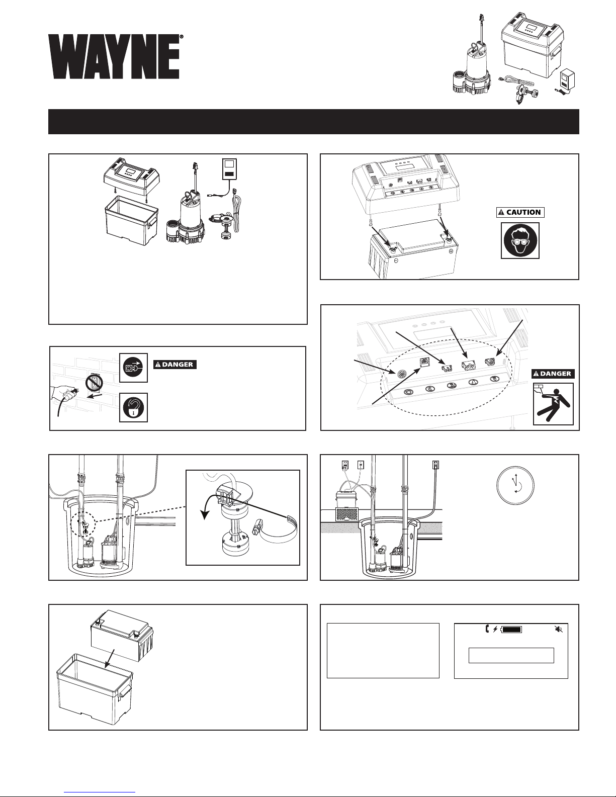
QUICK START INSTRUCTIONS WSM3300
STEP 1 - VERIFY PACKAGE CONTENTS
Transformer (1)
Lid and Controller Assembly (1)
Battery box (1)
12 Volt DC back-up pump (1)
Switch with clamp (1)
Requires active telephone land line service
Does not include:
12 Volt DC deep cycle
battery, phone jack,
phone line, pipe, and
necessary fittings.
STEP 2 - DISCONNECT POWER
If the power disconnect
is out of sight, lock in the open
position and tag it to prevent
unexpected application of power.
Failure to do so COULD result in fatal
electric shock!
STEP 5 - CONNECT LID TO BATTERY
Wear safety glasses when
connecting the battery
Red
Black
STEP 6 - CONNECT WIRES
Transformer
Security
Phone
Float Switch
DC Pump
STEP 3 - INSTALL BACK-UP AND FLOAT SWITCH
STEP 4 - INSTALL BATTERY
Acceptable Batteries
WAYNE - WSB1275
WAYNE - WSB1240
or
12 Volt Deep Cycle Marine Battery
12 Volt SLA (Sealed Lead Acid)
12 Volt Deep Cycle Battery
12 Volt Wet Cell Battery
Size = min 40Ah
STEP 7 - POSITION BATTERY AND CONTROLLER
Minimum charge time
before usage is 24 hours
Drain
Tile
STEP 8 - CONTROLLER SETUP
Home DisplayStartup Display
Select the starting language and follow the on-screen
instructions to set up the controller. Upon completion of
controller setup, restore AC power and test the main pump as
described in the operation section of the manual.
© 2012, WAYNE/Scott Fetzer Company.
For parts, product & service information
visit www.waynepumps.com
354100-001 10/12
Page 2
12 Volt Advanced
Notification System
OPERATING INSTRUCTIONS & PARTS MANUAL
READ, UNDERSTAND AND FOLLOW ALL INSTRUCTIONS IN THIS MANUAL - DO NOT DISCARD.
Failure to follow these instructions could result in property damage, bodily injury or death.
INSTALLATION AND OPERATING INSTRUCTIONS
DESCRIPTION
The 12 Volt Advanced Notification System includes a DC backup sump pump, an electronic controller with digital display, and
an auto-dialer. Optimal back-up power is supplied by a 12 volt
battery (not included). The system is designed for home sump
applications. When an electrical power outage occurs, the
electronic controller automatically switches the sump pump to
battery power. Power loss will initiate a phone call via the autodialer to the phone number(s) entered by the homeowner. With
a 24-hour monitor and a predetermined full system check, the
system tells you it’s status via a digital display and alerts you to
potential problems with an audible horn and phone call.
UNPACKING
Inspect this unit before it is used. Occasionally, products are
damaged during shipment. If the pump or components are
damaged, contact customer service at 1-800-237-0987.
SAFETY GUIDELINES
To help recognize this information, observe the following signal
words/hazard classifications.
This is the safety alert symbol. It is used to alert you to
potential bodily injury hazards. Obey all safety messages that
follow this symbol to avoid possible harm.
Danger indicates an imminently hazardous
in death or serious injury.
Warning indicates a potentially hazardous
result in death or serious injury.
Caution indicates a potentially hazardous
in minor or moderate injury.
Notice indicates important information, that if
situation which, if NOT avoided, WILL result
situation which, if NOT avoided, COULD
situation which, if NOT avoided, MAY result
NOT followed, MAY cause damage to equipment.
GENERAL SAFETY INFORMATION
combustible liquids vapors or dusts.
Do NOT use to pump flammable/combustible liquids vapors
or dusts. Do NOT use in a flammable and/or explosive
atmosphere. Pump SHOULD be used to pump clear water
ONLY. Failure to follow these instructions WILL result in bodily
injury or death.
Electric shock hazard.
power before servicing. Apply a fixed
lock or tag to prevent unexpected application of power.
Electric shock hazard. DO NOT walk
on wet floor until power is disconnected. Use a
licensed electrician to perform service in accordance with the National
Electrical Code and all local codes.
This pump is NOT rated for use with flammable/
Disconnect
NEVER allow children to use pump.
clothing. Eye protection MUST be worn when
handling the battery.
and back-up sump discharge.
water. This pump is NOT designed to handle
effluent, salt water, brine, laundry discharge, or any other application
which MAY contain caustic chemicals and/or foreign materials. Pump
damage MAY occur if used in these applications and WILL void warranty.
SPECIFICATIONS
Power Supply Requirements ......120 V, 60 Hz
Motor ..........................................12 V DC Motor
Pump Dimensions ......................11 in. high x 8 3/4 in. base
CONSTRUCTION
Motor Housing ...........................
Impeller ......................................
Shaft ..........................................
Discharge ..................................
Float Switch ..............................
BATTERY INFORMATION
The system is designed to operate most efficiently
deep cycle, sealed lead (Pb) acid (SLA) battery. A deep cycle
marine battery can also be used. Sealed lead acid batteries cost
slightly more, but they can last longer than a wet cell battery and
are maintenance free. The oversize battery case (included) will
accomodate one 12 Volt battery up to a 27-frame size. Use a new
battery. Chart 1 illustrates the expected performance with various
battery combinations. Do not use batteries rated below 40 amp
hours. Be certain that the area around the battery is well ventilated.
Before servicing the battery, blow away gasses by waving a piece
of cardboard near the battery. An assistant should be present or
close enough to come to your aid in the event of an emergency.
Have a reliable source of fresh water and soap nearby in case
battery acid contacts clothing, skin or eyes. Wear eye and clothing
protection when working around lead acid batteries. Avoid touching
your eyes when working around lead acid batteries.
Explosion hazard. Smoking and open flames
prohibited. Battery recharging and
connections MUST be performed in a well ventilated area
CALIFORNIA PROPOSITION 65
This product or its power cord MAY contain
chemicals, including lead, known to the
State of California to cause cancer and birth defects or other
reproductive harm. Wash hands after handling.
Chemical hazard. If battery acid contacts
your eyes, immediately flush eyes with
copious amounts of clean, tepid water for at least 30 minutes. Seek
medical attention.
WSM3300
Battery acid is corrosive. Avoid spilling on skin or
A check valve MUST be used on the primary
A ground fault circuit interrupter is required.
This pump MUST only be used to pump clear
Thermoplastic
Thermoplastic
Stainless Steel
1-1/2 in. NPT
Dual Reed
with a
.
REMINDER: Keep your dated proof of purchase for warranty purposes! Attach it to this manual or file it for safekeeping.
© 2012, WAYNE/Scott Fetzer Company.
www.waynepumps.com
2
Page 3
Operating Instructions and Parts Manual
WSM3300
TRANSFORMER FEATURES
• Whenpluggedinto120VAC,thetransformerautomatically
provides power to the battery charging circuitry.
• Thetransformercanbeleftconnectedtothewalloutlet
indefinitely.
• Thetransformerisdesignedforthesystemonly,DONOT
use for any other purpose.
CONTROL BOX FEATURES
CHART 1 - STANDBY POWER PUMPING CAPACITY
*Hours of Protection During A Rain Event
If Your Sump Pump Runs...
Deep Cycle
Battery Size
40 A-Hr
75 A-Hr
1X Per
Min
12 Hours
23 Hours
1X Every
5 Min
53 Hours
100 Hours
*Assumes a typical 10 ft. rise on the discharge pipe, and
17 in. diameter sump pit. Results may vary.
BACK-UP PUMP:
1. The pump will turn on when either the bottom or top float
rises.
2. The pump motor will keep running for 15 seconds after the
float drops.
3. An auto-test of the back-up pump will occur every 14 days
between the hours of 5pm-7pm. The controller will report
any known issues and record the date of the last auto-test
on the home screen.
4. The last known float activated back-up pump run date can
be found by scrolling through the main menu selections.
Before disabling your main pump, have a stand by
pump ready or an appropriate means of evacuating the sump.
before servicing. Apply a fixed lock or tag to
prevent unexpected application of power.
Installation of this unit MAY take several hours.
Electric shock hazard. DISCONNECT power
1X Every
10 Min
92 Hours
172 Hours
PUMP INSTALLATION
1. Turn power to main pump off.
2. Pump must be installed using 1-1/4 in. or 1-1/2 in. rigid
PVC piping.
PUMP INSTALLATION
The 12 Volt Advanced Notification System can be installed as
a back-up system with a separate dedicated discharge line
(Method 1), or tied into an existing sump pump line (Method 2).
1. Verify that the existing AC pump is in good working order. If
the AC pump is questionable, replace with the same HP
pump or increase the HP rating if you have experienced
flooding or the pump is not keeping up with the inflow of
water.
2. Remove any silt or accumulated debris from the sump pit
and surrounding area.
3. Make sure that disconnecting the AC pump will not create a
flood in your basement. A pump should be available to
evacuate water in the event incoming water rates should
change.
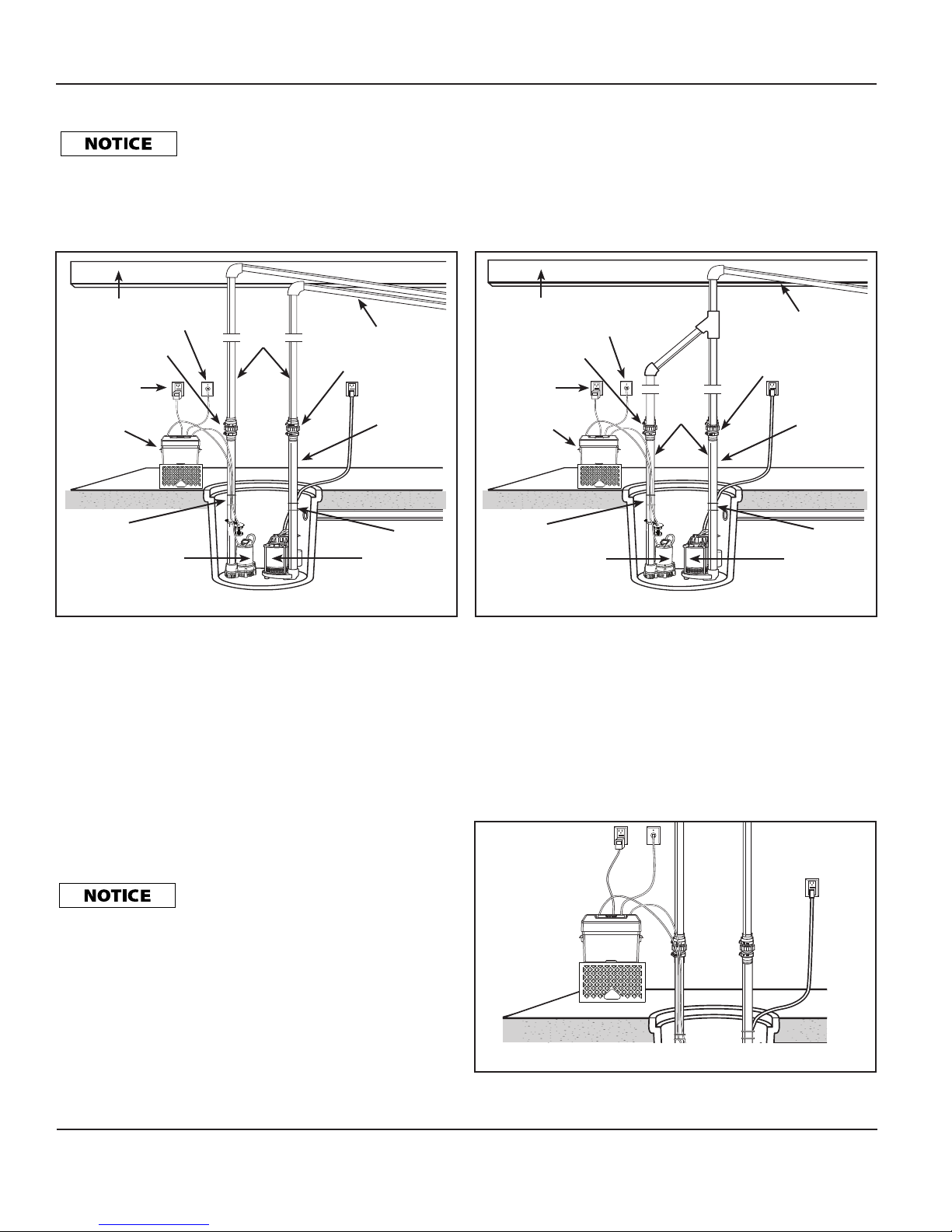
METHOD 1 (PREFERRED) - See Figure 1
discharge line of both the main AC pump and the
back-up DC pump. Failure to install the check valves MAY allow water to
recirculate into the sump pit. See Figures 1 and 2.
1. Locate the DC pump on a solid, level surface in the sump pit. Do
NOT place the pump on a loose or sandy surface. Small stones or
sand may damage the pump resulting in pump failure.
2. This pump has a 1-1/2 in. NPT discharge. If a 1-1/4 in.
discharge pipe is desired, an adapter (not included) will
be necessary. Smaller diameter piping will reduce pump
flow-rate and performance.
3. A check valve is required in the discharge line of both the
Main AC pump and the Back-Up DC Pump to prevent
recirculation of water into the sump pit. The system will not
function without two check valves.
4. Cut a 4 ft. section of 1-1/4 in. or 1-1/2 in. diameter rigid PVC
pipe. Cement 1-1/4 in. or 1-1/2 in. pipe to a threaded fitting.
Cement 1-1/4 in. or 1-1/2 in. pipe into pipe coupling. Attach
1-1/4 in. or 1-1/2 in. pipe section to the Back-Up DC Pump
discharge adapter.
5. Screw into pump discharge.
DO NOT over tighten or cross-thread plastic
fittings or check valves. USE rigid PVC or metal
pipe for permanent installation.
6. Place the pump with the 4 ft. section of PVC pipe on a solid,
level surface in the sump pit on an elevated surface.
7. Attach a rubber check valve (sold separately) to the top of
the discharge pipe. This will allow the pump or check valve
to be removed easily for servicing.
8. Check valve is recommended for effective operation of
system.
The remainder of the discharge pipe installation will vary
depending on individual circumstances. Using sound plumbing
practices, route the discharge pipe to an exterior wall by the
shortest path. Keep turns to a minimum because they reduce
flow output of the pump. The pipe that exits the building structure
should be sloped downward so that water will not freeze in the
pipe.
When installing the separate discharge pipe, drill through
the outside wall with appropriate drilling equipment. Seal the
hole to prevent water from entering.
Check valves MUST be installed in the
www.waynepumps.com
3
Page 4
Operating Instructions and Parts Manual
WSM3300
METHOD 2 - See Figure 2
discharge line of both the main AC pump and
the back-up DC pump. Failure to install the check valves MAY allow
water to recirculate into the sump pit. See Figures 1 and 2.
Check valves MUST be installed in the
If a separate, dedicated discharge is not possible as in Method
1, the Back-Up DC Pump can be tied into the AC-operated
pump’s discharge pipe by installing a “Y” or "T" connector.
Two check valves will be required.
Floor Joist
Phone Jack
Check Valve
Transformer
12 Volt
Advanced
Notification
System
Zip Tie
Back-Up DC Pump
Rigid
PVC
Pipe
Slope Pipe Down
Check Valve
1-1/4 in.
or
1-1/2 in.
PVC Pipe
Zip Tie
Primary Pump
9. Glue a 45º elbow to the short pipe on the Back-Up DC
Pump. Glue a “Y” adapter to the short pipe on the existing
pump, as shown in illustration for Method 2.
10. Glue a short piece of PVC pipe between the 45º elbow and the
“Y”.
The remainder of the discharge pipe installation will vary
depending on individual circumstances. Using sound plumbing
practices, route the discharge pipe to an exterior wall by the
shortest distance
Floor Joist
Check Valve
Transformer
12 Volt
Advanced
Notification
System
Zip Tie
Back-Up DC Pump
.
Phone Jack
Rigid
PVC
Pipe
Slope Pipe Down
Check Valve
1-1/4 in.
or
1-1/2 in.
PVC Pipe
Zip Tie
Primary Pump
Figure 1 - Method 1 (Preferred Installation)
1. Locate the Back-Up DC Pump on a solid, level surface in the
sump pit. Do not place the pump on a loose or sandy surface.
Small stones or sand may damage the pump resulting in
pump failure.
2. This pump has a 1-1/2 in. NPT discharge. If a 1-1/4 in.
discharge pipe is desired, an adapter (sold separately, part
#66002-WYN1 WAYNE adapter or equivalent) will be
necessary. Smaller diameter piping will reduce pump
flow-rate and performance.
3. A check valve will be required in the discharge line of both
the Main AC pump and the Back-Up DC pump to prevent
recirculation of water into the sump pit. System will not
Figure 2 - Method 2 (Alternate Installation)
METHODS 1 AND 2
Install float switch at least 10 in. -12 in. above bottom of sump
pit so that back-up unit turns on only when the water level is
higher than the normal “on” level for main pump. Make sure
power wires and hose clamp ends do not interfere with float
switch, pump inlet, or main pump operation. The back-up
pump must not be allowed to run dry except during the 20
second "auto-test. Incoming water can not flow directly onto
the float switch. Failure to position properly may cause improper
operation. Position the float switch so that it will not interfere
with any portion of the plumbing, wiring, or sump pit. Check for
clearance by lifting both floats.
function without two check valves.
4. Cut a 4 ft. section of 1-1/4 in. or 1-1/2 in. diameter rigid PVC
pipe. Cement 1-1/2 in. pipe to a threaded fitting. Cement
1-1/4 in. pipe into pipe coupling. Attach 1-1/4 in. pipe
section to the Back-Up DC Pump discharge adapter.
Do NOT strip or cross thread plastic
fittings or check valves. Flex hose is NOT
recommended. Rigid PVC or metal pipe is required for permanent installation.
5. Screw into pump discharge.
6. Place the pump with the 4 ft. section of PVC pipe on the
sump floor or on an elevated surface if required.
7. Attach a rubber check valve (sold separately) to the top of
the discharge pipe. This will allow the pump or check valve
to be removed easily for servicing.
8. Duplicate the discharge piping arrangement for the primary
AC pump if the existing discharge line has to be adjusted to
accommodate a second pump.
Figure 3 - 12 Volt Advanced Notification System elevated
www.waynepumps.com
4
Page 5

*
Operating Instructions and Parts Manual
WSM3300
CONTROL BOX INSTALLATION
result, and warranty WILL be void.
transformer to a properly grounded
GFCI (Ground Fault Circuit Interrupter) receptacle that is rated
for at least 5 amps. Test the operation of the GFCI receptacle
according to the manufacture's recommended intervals
DISCONNECT AC power before connecting or disconnecting the battery.
Use the system indoors, in a well ventilated
area. Do NOT expose to rain or snow. Do NOT use
an extension cord. Do NOT disassemble. Be sure battery box ventilation
holes are unobstructed. If dropped or damaged, do NOT operate; contact
manufacturer for service.
flames prohibited. Battery
recharging and connections MUST be performed in a well
ventilated area. Before servicing the batteries, blow away
the gases by waving a piece of cardboard near the batteries.
1. Place battery box and controller within six feet of the sump
and a 120 VAC separately fused outlet. The outlet must be
protected by a ground fault circuit interrupter (GFCI). The
area must also be clean, dry, and well-ventilated.
2. Wave cardboard over batteries to blow away any gas that
may be present.
3. Connect the power wires from the 12 Volt Advanced
Notification System to the battery terminals as shown in
(Figure 4). Connect the red wire to the positive
terminal of the battery and then connect the black wire
to the negative terminal of the battery. The display
should be lit up at this time. If connected improperly an
alarm will sound until corrected.
4. Plug the pump and float switch connectors into the
12 Volt Advanced Notification System. The connections are
marked. (See Step 6 in the Quick Start Guide)
5. Follow the on-screen instructions. Test pump operation
by filling the sump with water while the main pump is
unplugged. If the back-up pump operates properly, plug the
transformer into the GFCI protected outlet to begin charging
the battery.
surfaces, oil, and chemicals. Avoid kinking the
cord and replace damaged components immediately.
Black
Figure 4 - Battery terminal connection
If battery cables are reversed, damage to the
transformer
Electric shock hazard. Connect this
Explosion hazard. Smoking and open
Protect electrical cord from sharp objects, hot
, controller or battery COULD
.
Be sure to
connect the
cables as
shown, reversing
Red
the cables will
cause damage
to the product.
PHONE LINE INSTALLATION
PHONE SYSTEM INFORMATION
Sharing the phone jack:
The 12 Volt Advanced Notification System and your existing
phone/fax can share the same wall jack. A standard phone
jack splitter also known as a line splitter (not provided) can be
purchased at your local hardware store. Install as shown in
Figure 5. The splitter allows independent operation of both units
without interference.
Open
Phone Jack
If you have an
open phone
service jack
available, a line
splitter is not
required.
The phone cords
may need to be longer depending
upon the distance to the available
phone service jack.
Figure 5 - Phone line splitter/hookup
PHONE SERVICE AND POWER OUTAGES
The 12 Volt Advanced Notification System is designed and
certified by the FCC to operate on a standard telephone line and
connects to a standard phone jack. The System dials out using
touch tone dialing only. Must have an active phone line that is
detectable by the 12 Volt Advanced Notification System.
The 12 Volt Advanced Notification System does work with
DSL, Cable, or Digital phone services with the appropriate
in-line filters. If the modem doesn’t produce a “dial tone” it
will not be able to place a phone call. If the 12 Volt Advanced
Notification System is unable to place a call while using one of
these services, please contact your phone service provider for
assistance.
POWER OUTAGES: DSL, Digital, and Cable
provided phone services DO NOT WORK
when AC Power is lost. The 12 Volt Advanced Notification System
will NOT be able to call out if the power is out when using these
phone services. A back-up battery system (UPS-uninterrupted
power supply) is required to keep the modem and/or system active
for a minimum of 8 hours. Check with your phone service provider
for details regarding UPS sizing for your installation. Standard
telephone lines are self-powered by the telephone company and
usually not affected unless the phone service itself is interrupted.
PHONE NUMBER ENTRY AND STORAGE
The 12 Volt Advanced Notification System uses an onboard
auto-dialer and microprocessor to place pre-recorded phone
calls regarding the status of your back-up system. The System
is capable of notifying up to three phone numbers (60 digits
each) of your choice. The System stores each of your phone
numbers locally and will not lose or erase your phone numbers
due to a power outage or battery dying. Before you start
entering phone numbers, DO NOT enter phone numbers of
emergency services (fire, police, or ambulance).
CELL PHONES: The 12 Volt Advanced Notification System will
call all phones that a basic telephone will connect with. It does
not differentiate between a cellular phone or land line phone.
Cellular calls are based upon having adequate reception.
Shared
Phone Jack
Line Splitter
(not provided)
Phone/FAX
Cord
12 Volt Advanced
Notification System
www.waynepumps.com
5
Page 6

Operating Instructions and Parts Manual
WSM3300
CRITICAL STEP: It is recommended that a person at the call-to
location confirms receiving the test phone call. Validate all calls
before concluding that the system setup is finished.
ENTERING AND CHANGING PHONE NUMBERS
When programming phone numbers into the System, enter each
phone number into the phone setup screens exactly as you
would when making a personal phone call.
Two phone number entry methods:
1. As part of the Installation Setup procedure (follow the on
screen prompts) or,
2. From the “Home Screen”, select “MENU”, enter the security
code (if prompted), then locate the “Phone Setup” option
and then press the button for “ENTER”.
a. You can modify, delete, or verify within this selection.
b. To delete any number, simply press “DEL” and it will
backspace as needed.
c. To EDIT a number, re-enter the phone number and it
will overwrite the existing number.
PROPER PHONE NUMBER ENTRY
System can place local calls, long distance calls, and even
international calls. The use of calling cards is not recommended
for they are difficult to enter and can change without notice and
result in a phone call never being made.
Example:
*Local Number: 123-4567
*Long Distance: 1 (555) 123-4567
* International: Country code, followed by 1, then the
phone number. For proper dialing instructions or
further assistance, contact your service provider.
Enter the phone number exactly as you would when
dialing a call yourself. If your local number requires the
area code, enter as needed.
CREATING PAUSES WHEN ENTERING PHONE NUMBERS:
Some phone calls require accessing an outside telephone line
from a digital system. Obtain the digit(s) necessary to access
the outside line (dialing “9” to access an outside line is most
common). A time delay may be required to let the system fully
access the outside line and this is accomplished by entering
two “stars” (**) after dialing the 9.
The following examples use a “9” to access the outside phone
line followed by a 2 second delay before the auto-dialer is
initiated to place an automated phone call by the System:
Local call: 9** then 123-4567
Long distance call: 9** then 1 (555) 123-4567
TIME DELAYS
** = 2 seconds, **** = 4 seconds, ****** = 6 seconds
All stars (*) must be entered in multiples of 2 or the system will
not recognize them as actual time delays.
PHONE TEST
After entering all phone numbers, it is crucial that you test your
System to verify that it can reach the call list phone numbers.
System is in "test mode".
TESTING YOUR 12 VOLT ADVANCED NOTIFICATION SYSTEM
PHONE NUMBERS
To test the System, do the following:
1. Make sure the System is powered up, phone line is
connected, and the "Home Screen" has no error messages.
The CANCEL key does not function when the
To make sure all timers and errors are cleared from the
system memory, press and hold the "RESET" button for
a minimum of 3-5 seconds.
2. Press the MENU button followed by the “Phone Setup”
option.
3. Scroll to the desired phone number, hit ENTER, then select
the TEST option.
The system will immediately dial the desired phone number.
Upon answering, the unit will play the following message: “This
is a test of the back-up system.” It will repeat this message for
approximately “1” minute and then hang up. The display will
prompt you asking if the test was successful, if Yes, it returns to
the home screen. If “NO”, it will retest.
4. Repeat Steps 2 and 3 to test the remaining phone numbers.
The System does not provide any indication of call success;
therefore, you must verify that the call was made successfully.
TESTING FOR A SPECIFIC ALARM CONDITION
To test for a specific alarm condition you will have to simulate
that specific alarm condition and then verify if the alarm phone
calls went through. In those scenarios, you must cancel the
alarm call out sequence and correct the alarm condition by
pressing and holding the RESET button for a minimum of 5
seconds.
HOW THE SYSTEM WORKS WITH VOICE MAIL OR AN
ANSWERING MACHINE
When it is necessary to connect an answering machine or voice
mail device to the same phone line as the System, you can still
use all the features of these devices, along with being able to
check status and cancel an alarm call out of the System.
HOW THIS WORKS:
The System can answer incoming calls to check the system
status. To do this, the ring count must be set to answer on
either “5” or “10” rings (default setting is 10 rings, change this
setting from the Main Menu>Set Ring Count).
Set your answering machine or voice mail to answer in fewer
rings than the System. (For example, if the System is set to
answer on 5 rings, set the answering machine/voice mail to
answer in “4” or fewer rings.) Therefore, when a call comes into
the location of the System, the answering machine/voice mail
will respond first because it is set to answer in fewer rings than
the System.
RING COUNT TIMER
The ring count timer works in the following way: when the first
call comes in during an alarm event, the internal system timer
starts counting down for “3” continuous minutes. If the System
receives enough rings to answer (within “3” minutes), it will
respond, and the ring counter will reset to “0” regardless if the
three minutes have elapsed or not. Also, the timer will reset
to “0” if no additional calls are received during a three minute
period (multiple calls to the System within “3”minutes will not
reset the ring timer).
CALLING THE 12 VOLT ADVANCED NOTIFICATION SYSTEM
DURING AN ALARM EVENT
Example:
1) The back-up system is set to answer in 5 rings (ring count
setting).
2) The answering machine/voice mail is set to answer in "4"
rings or fewer.
To get the System to respond given the above example criteria,
do the following:
1. Call the phone number of the location where the
System is located, and let the phone ring “3” times
and then hang up. The internal 3-minute timer starts and
www.waynepumps.com
6
Page 7

Operating Instructions and Parts Manual
WSM3300
the System tallies and remembers the number of rings.
2. On your second call within “3” minutes, let the phone ring
until the System answers. The System will answer
first because it remembered the first “3” rings, and then
answers with an audible system status. If done properly, the
answering machine/voice mail will not answer.
If the System is set to answer in 10 rings (one of
the Menu selectable options), you will need to
place more calls within "3" minutes to get the System to eventually answer.
HOW TO CANCEL ALARM PHONE CALLS FROM YOUR
SYSTEM
To cancel the alarm phone call from one of the numbers in the
phone call list:
To cancel a call out sequence from the System while listening to
an alarm message, do the following:
1. Answer the phone call.
2. Listen to the alarm message.
3. When told, press the number “1” key followed by the
pound (#) key within “1” minute to cancel the alarm call
out. You can cancel the call at anytime during the
message.
4. You can listen until you hear the System say goodbye
or just hang up the phone.
5. If you do not cancel the call, the system will call the next
number in your phone number list. The first cancel will
stop all calls for all numbers. This sequence will repeat
every 15 minutes until a call is cancelled.
To cancel the alarm phone call using the System display:
Press and hold the RESET button once to cancel the call (phone
icon is present) and the RESET up to 5 seconds if multiple
errors/alarms are present on the display to stop receiving phone
calls. You will then be required to also clear/reset the message(s)
on the display.
Canceling the call out sequence does not
cancel an active alarm. System will continue
to beep and the alarm message will be displayed on the digital display
until you hit reset for each message/condition. If you do not hit reset, each
alarm message on the display system will recall the phone number(s) in
the last 72 hours as a reminder for the uncleared alarm conditions.
PLACE A PHONE CALL TO YOUR SYSTEM TO CANCEL AN
ALARM
To cancel a call out sequence during an active alarm condition,
do the following:
1. Make the call to the System (phone number at alarm
location)
2. Wait for the System to answer (5 or 10 rings Menu option
selectable)
3. Listen to the alarm message.
4. Press the number “1” key followed by the pound (#) key
anytime during the message to cancel the alarm call out
and then hang up the phone.
REMOTE STATUS CHECK
The System will answer incoming calls if a warning condition
exists on the display. When no alarm issue exists, you will get
a general status update. If the call out sequence has been
cancelled for an alarm by pressing "1" then "#" on the phone,
but the alarm condition still exists on the display, the System will
answer and describe the alarm condition.
CANCELING AN ALARM CALL OUT SEQUENCE WITH AN
ANSWERING MACHINE/VOICE MAIL DEVICE ON THE SAME
PHONE LINE
To cancel the alarm call out-sequence, do the following:
STEP ACTION
1. Make the call to the System (phone number at alarm
location).
2. Let the phone ring the desired number of times (before the
other in-line answering machine/voice mail can answer), Hang
the phone up.
3. Call the number a second time within three minutes (The
System keeps track of all the rings from the previous
calls, accumulates them until the total ring count matches its
ring count number, 5 or 10, and then it will answer). Listen to
the alarm message.
4. Press the number “1” key followed by the pound (#) key
anytime during the message to cancel the alarm call out. Hang
up the phone.
OPERATION
1. After installation, the back-up pump will start once the water
level raises the bottom float.
2. The System has a charging circuitry designed to optimize the
recharging time of your battery and to prevent overcharging.
In addition, the control box has a time delay which keeps the
pump from repeated, short cycles when it shuts off. This
time delay feature will allow the pump to run 15 seconds
after the switch reaches the off position.
3. MUTE FUNCTION: Press the mute button once to silence the
alarm for 12, 24, or 48 hours (menu selectable). To turn off the
mute timer, press and hold the RESET button down for 5
seconds.
BATTERY CARE AND MAINTENANCE
and open flames prohibited.
Battery recharging and connections MUST be performed
in a well ventilated area. Before servicing the batteries,
blow away the gases by waving a piece of cardboard near
the batteries.
1. Unplug the transformer.
2. For batteries with top caps that can be removed, the
electrolyte level should be checked and filled to
manufacturer’s specifications. The charge for each cell
should be checked with a hydrometer. A specific gravity of
1.265 indicates the battery is at full charge. If the specific
gravity of any of the cells varies more than .050, the battery
should be replaced.
3. If the battery fluid levels are low or battery plates are exposed,
refer to the manufacturer's recommendations on how to
replenish properly.
4. Inspect the terminals and clamps for corrosion and
tightness. Clean and tighten as required.
An inexpensive hydrometer can be purchased at
an automotive parts dealer.
EXTENSION CORDS
We DO NOT recommend using extension cords, but if you find it
absolutely necessary then:
1. Use at least a 16 gauge cord that does not exceed 50 feet
in length.
Explosion hazard. Smoking
www.waynepumps.com
7
Page 8

Operating Instructions and Parts Manual
ADVANCED NOTIFICATION
MESSAGE ON UNIT SCREEN
PRIMARY PUMP STATUS
AC Power Interrupted
Primary Pump Suspect
BACK-UP DC PUMP STATUS
DC Pump In Operation
DC Pump Not Operable (Failed Test)
Check Floats For Debris
Capacity Overflow Possible
DC Impeller Locked
BATTERY TRANSFORMER
Transformer Bad
Blown Controller Fuse
MICROPROCESSOR CONTROLLER
CONDITION
12 V BATTERY STATUS
DC Pump Under Test
Battery Fully Charged
Battery 80% Charged
Battery 60% Charged
Battery 40% Charged
Battery 20% Charged
Battery Dead
Battery Condition Questionable
CALL PHONE
AUDIBLE ALARM
SECURITY SYSTEM
Reverse Polarity
WSM3300
2. The extension cord must have a ground wire and plug pin
and be connected to a properly functioning GFCI
receptacle.
3. Make sure the connection between the transformer and
extension cord are elevated off the floor.
SECURITY SYSTEM INSTALLATION AND SETUP
Electric shock hazard.
power before servicing. Apply a fixed
lock or tag to prevent unexpected application of power.
The advanced notification system produces auto-dialer alerts
and can also notify your 3rd party home security system
provider (if available). A qualified home security technician is
required when making connections between the two systems.
An access port is available on the back of the lid in which
the qualified technician can properly connect the advanced
notification system to the security system. (See Figure 5)
Figure 5 - Security system setup
this step. Be sure not to damage any
components on the control board.
The inner shield will have to be removed during
Disconnect
FOR SIGNAL
USAGE ONLY. NC/NO Output:
12 Volt DC, 2 amp max.
must be provided to the telephone company.
PLUG AND JACK USE
A plug and jack used to connect this equipment to the premises
wiring and telephone network must comply with the applicable
FCC Part 68 rules and requirements adopted by the ACTA.
A compliant modular plug is provided with this product. It is
designed to be connected to a compatible modular jack that is
also compliant. See installation instructions for details.
RING EQUIVALENCE NUMBER (REN)
The REN is used to determine the number of devices that may be
connected to a telephone line. Excessive REN’s on a telephone line
may result in the devices not ringing in response to an incoming
call. In most, but not all areas, the sum of RENs should not exceed
five (5.0). To be certain of the number of devices that may be
connected to a line, as determined by the total REN’s, contact your
local telephone company. The REN for this product is listed on the
inside of the controller lid with the FCC identifier.
TELEPHONE NETWORK INTERFERENCES
If this System causes harm to the telephone network, the
telephone company will notify you in advance that temporary
discontinuance of service may be required. But if advance notice
isn’t practical, the telephone company will notify the customer
as soon as possible. Also, you will be advised of your right to
file a complaint with the FCC if you believe it is necessary. The
telephone company may make changes in its facilities, equipment,
operations or procedures that could affect the operation of the
equipment. If this happens, the telephone company will provide
advance notice in order for you to make necessary modifications
to maintain uninterrupted service. If the equipment is causing harm
to the telephone network, the telephone company may request
that you disconnect the equipment until the problem is resolved.
If your home has specially wired alarm equipment connected to
the telephone line ensure the installation of your System does not
disable your alarm equipment. If you have questions about what
will disable alarm equipment, consult your telephone company or a
qualified installer.
At this time, you may wish to change the system settings.
Since both the auto-dialer and security system cannot access
the phone line at the same time, you must choose which
system the software accesses first. If you wish the security
system to have first priority, on the main menu, scroll to and
select the "SECURITY SETUP" option, select "Security has
Priority" and hit "Enter" to confirm. The factory default setting
is "Back-up has Priority".
If you choose, you can test the security notification by
simulating any of the security notification alerts. (See Figure 6)
DO NOT overtighten screw.
Replace the inner shield once all connections and tests have
been validated.
OPERATING INSTRUCTIONS
1. To test the back-up pump, unplug the main pump and
transformer and fill sump with water until the water lifts the
bottom float therefore activating the back-up pump. Repeat
this process two times to be sure pump is operating
normally.
2. If pump operates normally, plug the transformer into wall
outlet and plug the main pump back in. Verify the main
pump is operational by repeating step 1 above.
FCC STATEMENT
This equipment complies with Part 68 of the FCC rules and
the requirements adopted by the ACTA (American Council
for Terminal Attachments). On the inside cover of your unit
is a label that contains, among other information, the FCC
registration number for this product. If requested, this number
www.waynepumps.com
Figure 6 -Notification alerts chart
8
Page 9

Operating Instructions and Parts Manual
Troubleshooting Chart
Message Possible Cause(s) Corrective Action
BACK-UP PUMP
Pump Won't Run 1. Connections not secure
2. Low or defective battery
3. Float switch stuck
4. Defective or blown fuse
Motor Hums But Pump
Won't Run
Pump Runs But Pumps
Very Little or No Water
Pump Cycles Too
Frequently
CONTROLLER
Flood Emergency 1. Inflow exceeds pump rating
Check AC Pump 1. Float stuck or obstructed
Check Back-up Pump 1. Defective pump
Check BU Pump Fuse 1. Fuse blown 1. Replace fuse
AC Power Failure 1. Defective wall transformer
Less Than 1 Hr Run Time 1. Power outage
Replace Battery 1. Battery weak
Replace/Inspect Float 1. Float stuck
Check Power Supply 1. Wall transformer defective 1. Replace wall transformer
1. Defective battery
2. Impeller is locked
1. Check valve missing or improperly installed
2. Obstruction in discharge pipe
3. Discharge pipe length and/or height exceeds
capacity of pump
4. Low or defective battery
5. Blocked vent hole
1. Check valve problem 1. Check to make sure check valves installed between
2. Inflow exceeds pump rating
3. Battery has become depleted
2. Switch defective
3. AC power interrupted
4. Inlet clogged
5. Defective pump
2. Pump jammed
2. GFCI Tripped
3. Circuit breaker tripped
4. Power outage
2. Extended power outage
2. Battery more than 5 years old
3. Discharged and left uncharged for more than 3 days
4. Charging cycles exceed max
2. Float defective
1. Check all connections
2. Check battery and replace if low or defective
3. Make sure nothing is interfering with operation of switch
4. Check internal fuse located inside the controller lid. Pull
the transformer from the wall outlet and remove. If the
fuse is blown, replace with onboard 20 amp automotive
type fuse or equivalent
1. Check battery and replace if low or defective
2. Unplug pump, remove screen, and check to see if
impeller is free to turn. If impeller is locked, remove
the 7 screws on the bottom of the pump to release the
housing around the impeller. Remove the obstruction.
Reassemble pump and reconnect
1. Check to make sure check valves installed between
primary pump discharge and back-up sump pump are
functioning properly
2. Check for obstruction and clear if necessary
3. If discharge is too high, a separate line may be required
with a lower discharge height
4. Check battery and replace if low or defective
5. Check to make sure the back-up pump is not air locked.
Locate the vent hole, inspect, and clear the hole using a
pipe cleaner
primary pump discharge and back-up sump pump are
functioning properly
1. Restore AC pump
2. Incorporate auxiliary pump
3. Replace battery
1. Free float
2. Replace switch
3. Reset breaker or GFCI outlet
4. Clear debris
5. Replace pump
1. Replace pump
2. Clear obstruction
1. Replace wall transformer
2. Check for moisture and reset
3. Reset breaker
4. Notify Utilities Company
1. Notify Utilities Company
2. Prepare spare battery
1. Replace battery asap
2. Replace battery
3. Replace battery
4. Replace battery
1. Clear float and debris
2. Replace float
WSM3300
www.waynepumps.com
9
Page 10

Operating Instructions and Parts Manual
WSM3300
For Replacement Parts or
Technical Assistance, call
1-800-237-0987
Please provide following information:
- Model number
- Serial number (if any)
- Part description and number as shown in parts list
Address parts correspondence to:
WAYNE Water Systems
101 Production Drive
Harrison, OH 45030 U.S.A.
Ref. No. Description Order No. Quantity
1 Lid/Controller Assembly 60157-001 1
2 Float Switch with Clamp 60158-001 1
3 Transformer 60159-001 1
4 Back-up Sump Pump 60160-001 1
Limited Warranty
1
4
3
2
For two years from the date of purchase, WAYNE Water Systems Division ("WAYNE Pumps") will repair or re place, at its
option, for the original purchaser any part or parts of its Water Pumps (“Product”) found upon examination by WAYNE to
be defective in materials or work man ship. Please call WAYNE Pumps (1-800-237-0987) for instructions. Be pre pared to
provide the model number and the serial number when exercising this warranty. All transportation charges on Products or
parts submitted for repair or replacement must be paid by purchaser.
This Limited Warranty does not cover Products which have been damaged as a result of accident, abuse, misuse,
neglect, improper application, improper maintenance, or failure to operate in accordance with WAYNE Pumps' written
instructions.
THERE IS NO OTHER EXPRESS WARRANTY. IMPLIED WARRANTIES, IN CLUD ING THOSE OF MER CHANTABIL I TY AND FITNESS FOR A PARTICULAR PUR POSE, ARE LIMITED TO ONE YEAR FROM THE DATE
OF PURCHASE. THIS IS THE EXCLUSIVE REM E DY AND ANY LIABILITY FOR ANY AND ALL INDIRECT OR
CONSEQUENTIAL DAM AG ES OR EXPENSES WHATSOEVER IS EXCLUDED.
Some states do not allow limitations on how long an implied warranty lasts, or do not allow the exclusions or limitations
of incidental or consequential damages, so the above lim i ta tions might not apply to you. This limited war ran ty gives you
specific legal rights, and you may also have other legal rights which vary from state to state.
In no event, whether as a result of breach of contract warranty, tort (in clud ing negligence) or otherwise, shall WAYNE
Pumps or its suppliers be liable for any special, consequential, incidental or penal damages including, but not limited to
loss of profit or revenues, loss of use of the products or any associated equipment, damage to associated equip ment,
cost of capital, cost of substitute products, facilities, services or replacement power, downtime costs, or claims of buyer’s
cus tom ers for such damages.
You MUST retain your purchase receipt along with this form. In the event you need to exercise a warranty claim, you
MUST send a copy of the purchase receipt along with the material or correspondence. Please call WAYNE Pumps (800237-0987) for return authorization and instructions.
DO NOT MAIL THIS FORM TO WAYNE PUMPS. Use this form only to maintain your records.
MODEL NO._______________ SERIAL NO.__________________________ DATE_____________
ATTACH YOUR RECEIPT HERE
www.waynepumps.com
10
Page 11

Operating Instructions and Parts Manual
Copy, cut out and save the following Quick Reference Cut-A-Way Card for your records. These are especially useful when you are not at home
and need to contact the System to check the status, retrieve or cancel messages and alarms. It would also be useful to give this card to others
who are on the call notification list for your System.
Quick Reference Cut-A-Way Card
WSM3300
CALL YOUR SYSTEM TO CHECK SYSTEM STATUS:
(no answering machine or digital voice mail service)
1. Make a phone call to the System (phone number at alarm location).
2. Wait for the System to answer (either five (5) or ten (10) rings).
3. Listen to the message(s). If no alarms, hang up.
4. If alarm(s) exist, cancel calls by pressing the "1" key then pound (#) key, hang up.
TO CANCEL A CALL FROM YOUR SYSTEM:
1. Listen to the message(s). If no alarms, hang up.
2. If alarm(s) exist, cancel calls by pressing the "1" key then pound (#) key, hang up.
CALL YOUR SYSTEM TO CHECK SYSTEM STATUS:
(answering machine/digital voice mail set to 4 rings, the System set to 5 rings)
1. Make a phone call to the System (phone number at alarm location), let ring three (3) times, hang up.
2. Make a second call to the System within 3 minutes, the System will answer on the second ring
(3 rings + 2 rings, System answers on fifth (5th) ring).
3. Listen to the alarm messages.
4. Press the "1" key then pound (#) key anytime during the message to acknowledge and cancel the alarm.
5. Note: if answering service answers before the System does, start over and adjust additive rings.
www.waynepumps.com
11
Page 12

Système de notification
Select Language
English Español
Français
Last Auto Test: --/--/--
MENU MUTE RESET
12.1 V
System Armed & Ready
100%
12
3
6
9
préalable de 12 volts
MODE D’EMPLOI ET LISTE DES PIÈCES
LIRE, S’ASSURER DE COMPRENDRE ET SUIVRE TOUTES LES INSTRUCTIONS DE CE MANUEL - NE PAS JETER.
Le non-respect de ces instructions pourrait entraîner des dommages matériels, des blessures corporelles ou la mort.
INSTRUCTIONS DE DÉMARRAGE RAPIDE WSM3300
DÉTACHÉES
ÉTAPE 1 : VÉRIFICATION DU CONTENU DE L’EMBALLAGE
N’inclut pas :
la batterie à décharge
poussée de 12
volts c.c., la prise
téléphonique, la ligne
téléphonique, le
tuyau et les raccords
nécessaires.
Transformateur (1)
Assemblage couvercle et contrôleur (1)
Boîte de batterie (1)
Pompe de secours de 12 volts c.c. (1)
Interrupteur avec pince (1)
Requiert un service de ligne terrestre téléphonique actif
ÉTAPE 2 - METTRE HORS TENSION
Si la source de courant
n’est pas visible, verrouiller en
position ouverte (arrêt) et étiqueter
pour éviter tout rétablissement
inattendu de l’électricité. Le nonrespect de cette directive POURRAIT
entraîner une décharge électrique
mortelle !
ÉTAPE 3 - INSTALLER LA POMPE DE SECOURS ET
L’INTERRUPTEUR À FLOTTEUR
ÉTAPE 5 - BRANCHER LE COUVERCLE À LA BATTERIE
MISE EN GARDE Porter
des lunettes de sécurité
au moment de brancher la
batterie
Rouge
Noir
ÉTAPE 6 - BRANCHER LES FILS
Interrupteur
à flotteur
Pompe c.c.
Transformateur
Sécurité
Téléphone
ÉTAPE 7 - POSITIONNER LA BATTERIE ET LE CONTRÔLEUR
ÉTAPE 4 - INSTALLER LA BATTERIE
Batteries adaptées
WAYNE - WSB1275
WAYNE - WSB1240
Batterie marine à décharge poussée
de 12 volts
Batterie au plomb-acide scellée de
12 volts
Batterie à décharge poussée de 12
Batterie à cellule humide de 12 volts
Capacité = 40 Ah minimum
© 2012, WAYNE/Scott Fetzer Company.
ou
volts
Le temps de charge
minimum avant utilisation
est de 24 heures
Tuile de
drainage
ÉTAPE 8 - CONFIGURATION DU CONTRÔLEUR
Affichage principalAffichage au démarrage
Sélectionner la langue de départ et suivre les instructions à
l’écran pour configurer le contrôleur. Une fois la configuration
du contrôleur terminée, rétablir l’alimentation c.a. et vérifier la
pompe principale conformément à la description donnée dans
la section Fonctionnement de ce manuel.
Pour des renseignements sur les pièces, les produits et l’entretien,
visiter www.waynepumps.com
 Loading...