

Page 1
Suction Outlet
(Main Drain)
Suction Outlet
(Main Drain)
Valves OK Between
Pump and Tee
Pump
At Least
3 Feet
ANSI/APSP-16 (2011) Certified
Component Anti-Entrapment
Cover/Grate or Suction Fitting
ANSI/APSP-16 (2011) Certified
Component Anti-Entrapment
Cover/Grate or Suction Fitting
No Valves Between
Tee and Main Drains
SWIMMING POOL PUMP
OPERATING INSTRUCTIONS & PARTS MANUAL
MODELS - WIP150 / WIP100 / WIP90 (TITLE 20 COMPLIANT)
READ, UNDERSTAND AND FOLLOW ALL INSTRUCTIONS IN THIS MANUAL - DO NOT DISCARD.
Failure to follow these instructions could result in property damage, serious injury or death.
Installer: Please leave this manual for the owner's use.
QUICK START INSTRUCTIONS
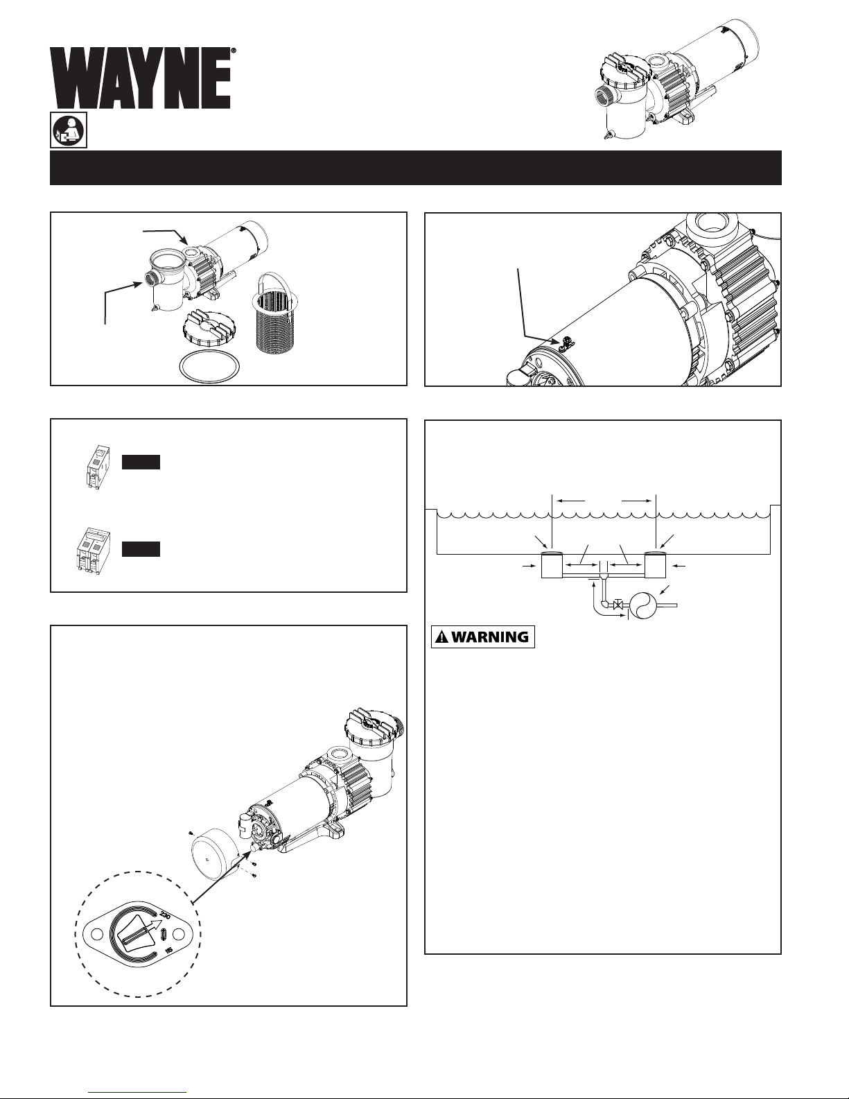
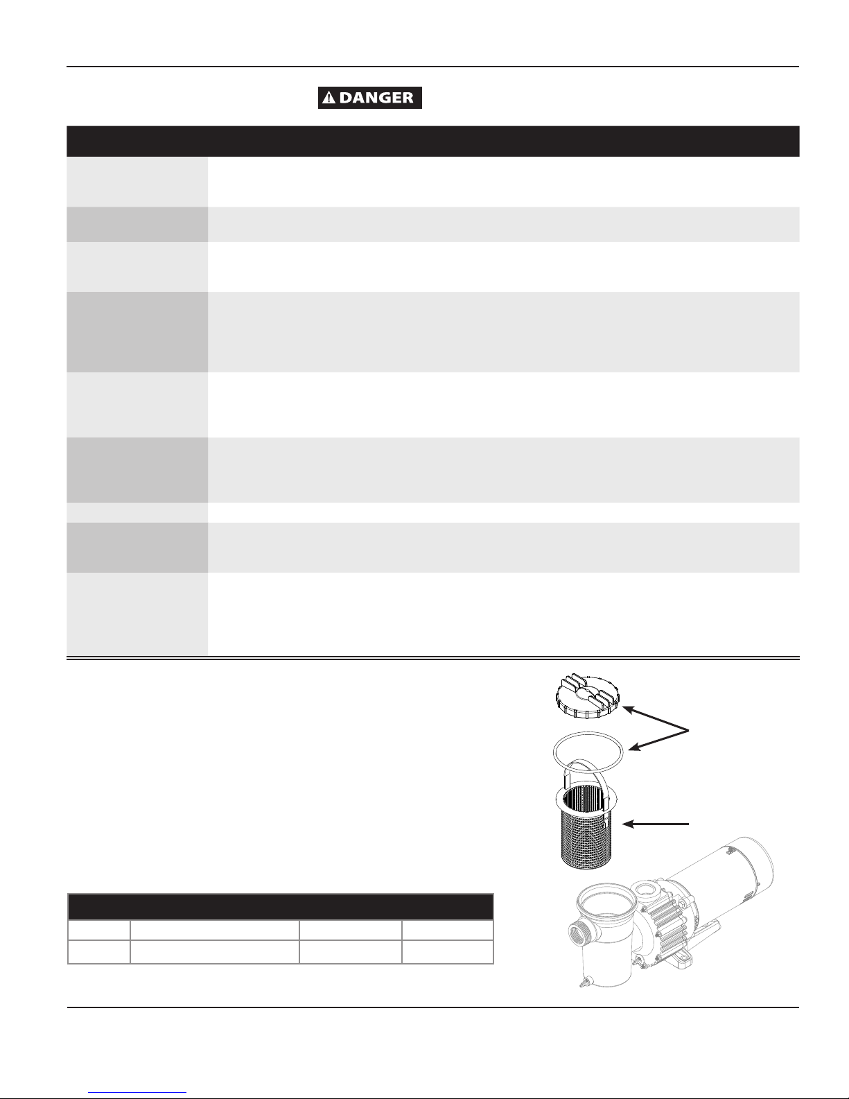
STEP 1 - VERIFY PACKAGE CONTENTS
WIP SERIES
SWIMMING POOL PUMP
STEP 4 - ELECTRIC BONDING
DISCHARGE
(1) PUMP
(1) LID
(1) GASKET
SUCTION
INLET
(1) STRAINER
STEP 2 - VERIFY EXISTING PUMP VOLTAGE
115 V
230 V
All electrical wiring or service should
be done by a qualified electrician.
You
must match the voltage of our pump to
the existing power supply.
STEP 3 - HOW TO CHANGE VOLTAGE SELECTOR
This pump is factory wired for 230 volts. To change the voltage to
115 volts follow the steps below:
1. Disconnect the pump from power.
2. Remove cover from back of motor to find voltage selector.
3. Pull selector knob out.
4. Rotate selector knob to correct voltage setting.
5. Push selector knob back in place.
6. Reinstall cover to back of motor.
Use solid copper bonding conductor
not smaller than 8 AWG (8.4 mm2).
STEP 5 - PUMP PLUMBING
Before attempting installation of any swimming pool pump, read and
understand ALL guidelines (ANSI/APSP/ICC-15 2011) regarding suction
and installation. Suction pipe should be as large or larger than discharge
pipe. Avoid using a suction pipe smaller than pump connection.
WARNING – DO NOT attempt installation
of swimming pool pump unless you have read
and understand the following standards, guidelines and regulations:
ANSI/APSP-16 (2011); ANSI/APSP-7 (2006); ANSI/ASME A112.19.17
(2010); ASTM F2387 (2004); Virginia Graeme Baker Pool and Spa Safety
Act (2007); CPSC’s publication entitled Guidelines for Entrapment
Hazards; and any successor standards or state law requirements.
DO NOT enter the swimming pool if any drain cover is broken or
missing. Close the swimming pool or spa. Immediately call your
professional to make repairs. Prime pump before attempting to operate.
To prime pumps located above water level, remove strainer cover, fill
strainer body with water then replace cover. If pump and all piping is
located below water level, the pump will self prime.
VOLTAGE SELECTOR
© 2012,
WAYNE/Scott Fetzer Company.
After pump has been primed, energize motor and open all suction and
discharge line valves. If no flow is observed in five minutes, stop the
motor and re-prime. If the pump fails to operate, check for air leaks.
Refer to troubleshooting section.
After about 10 minutes of operation, check the return fittings for air
bubbles. A continuous flow of air indicates leaks in the suction line.
Locate and correct any leaks immediately.
FOR FURTHER INSTRUCTIONS, SAFETY REQUIREMENTS/
STANDARDS/ REGULATIONS FOR INSTALLATION REFER
TO THE INFORMATION PROVIDED IN THIS MANUAL.
For parts, product & service information
visit www.waynepumps.com
320405-001 10/12
Page 2

SWIMMING POOL PUMP
OPERATING INSTRUCTIONS & PARTS MANUAL
MODELS - WIP150 / WIP100 / WIP90 (TITLE 20 COMPLIANT)
READ, UNDERSTAND AND FOLLOW ALL INSTRUCTIONS IN THIS MANUAL - DO NOT DISCARD.
Failure to follow these instructions could result in property damage, serious injury or death.
Installer: Please leave this manual for the owner's use.
INSTALLATION AND OPERATING INSTRUCTIONS
DESCRIPTION
Swimming pool pumps are a part of a water filtration system for swimming
pools. These pumps circulate water as part of an in-ground or an aboveground swimming pool.
UNPACKING
Inspect this unit before it is used. Occasionally, products are
damaged during shipment. If the pump or components are
damaged, contact customer service at 1-800-237-0987.
SAFETY GUIDELINES
To help recognize this information, observe the following signal
words/hazard classifications.
This is the safety alert symbol. It is used to alert you to
potential bodily injury hazards. Obey all safety messages
that follow this symbol to avoid possible harm.
Danger indicates an imminently hazardous
in death or serious injury.
Warning indicates a potentially hazardous
result in death or serious injury.
Caution indicates a potentially hazardous
in minor or moderate injury.
Notice indicates important information, that if
equipment.
NOTE: Note indicates information that requires special attention.
situation which, if NOT avoided, WILL result
situation which, if NOT avoided, COULD
situation which, if NOT avoided, MAY result
NOT followed, MAY cause damage to
GENERAL SAFETY INFORMATION
GENERAL SAFETY
1. Read the manual(s) included with this product
carefully. Be thoroughly familiar with the controls
and the proper use of the equipment. Follow all
instructions.
2. Only persons well acquainted with these rules of
safe operation should be allowed to use the unit.
Do NOT allow children to use this pump.
3. Wear safety glasses at all times when working
with pumps.
4. The unit MUST be wired into a properly grounded
GFCI circuit. Consult with a qualified electrician
for proper installation of a GFCI circuit.
swimming pools. If specified, the pump may
be used with hot tubs and spas. Do NOT use with storable pools. A
permanently installed pool is constructed in or on the ground or in a
building such that it CANNOT be readily disassembled for storage. A
storable pool is constructed so that it MAY be readily disassembled for
storage and reassembled to its original integrity.
This pump is for use with permanently installed
clear water. Do NOT pump
flammable or explosive fluids such as gasoline, fuel oil,
kerosene, etc. Do NOT use in a flammable and/or explosive
atmosphere. Failure to follow these instructions COULD
result in personal injury and/or property damage.
that is familiar with swimming pool/spa operations
and in accordance with the NFPA 70 - National Electric
Code.
allow leaves, debris, or foreign matter to collect around the
pump motor. Keep ventilation holes open. Allow motor to
cool before handling. Keep flammable liquids away.
ABBREVIATED TERMS AND DEFINITIONS
ASHRAE: American Society of Heating, Refrigeration and Air
Conditioning Engineers
ANSI: American National Standards Institute
APSP: The Association of Pool and Spa Professionals
ASME: American Society of Mechanical Engineers
CPSC: Consumer Products Safety Commission
NEC: National Electric Code
NFPA: National Fire Protection Association
Do NOT use pump if any part of the housing
Electric Shock
Hazard.
DISCONNECT power before servicing.
Apply a fixed lock or tag to prevent
unexpected application of power.
This unit is NOT designed for use
in sump, septic tanks or
underground vaults. NEVER use in hazardous or explosive
locations.
SWIMMING POOL SAFETY GUIDELINES
RESPONSIBLE ADULT SUPERVISION
Constant and responsible adult supervision is mandatory in the swimming
pool or spa environment. ALWAYS supervise children around swimming
pools and spas. NEVER allow a child to play in a way that COULD permit
the child’s hair to come near the drain cover.
Do NOT allow children to use
this pump.
Do NOT install multiple pumps in one hydraulic circuit. The pump is not
designed to accept output flow from another pump. Do NOT allow water
to backflow through the pump. Water flowing in the discharge and out
the suction during an upset condition can cause the motor to rotate
Risk of explosion! Pump only
This pump must be installed by a
licensed or certified electrician
Risk of fire and burn hazard! Motors
run at high temperatures. Do NOT
is cracked, broken, or missing.
WIP SERIES
SWIMMING POOL PUMP
REMINDER: Keep your dated proof of purchase for warranty purposes! Attach it to this manual or file it for safekeeping.
For parts, product & service information visit www.waynepumps.com
© 2012,
WAYNE/Scott Fetzer Company.
2
Page 3
WIP SERIES POOL PUMP
backwards. NEVER attempt to start pump if shaft is rotating due to a
hydraulic turbine action, this COULD cause pump to operate in reverse
and damage internal components.
DRAINS, SUCTION FITTINGS AND JETS
1. Do not allow anyone, child or adult, to play with or sit on any suction
outlet (drain) or wall vacuum fittings!
2. Pull long hair back into a ponytail or a bathing cap.
3. Remove jewelry before entering the swimming pool.
4. Have a licensed professional inspect all suction outlets.
5. Ensure that drain covers are ANSI/APSP-16 (2011) certified and wall
vacuum fittings are self closing/self latching.
6. Replace any broken drain covers, missing covers or uncertified covers
with ANSI/APSP-16 (2011) certified covers.
ELECTRICAL HAZARDS
A licensed electrician, experienced in swimming pools and spas, SHOULD
inspect your equipment to make sure everything is properly grounded,
bonded and protected by proper GFCI circuits according to Article 680 of
the National Electric Code.
INDOOR INSTALLATIONS
Swimming pools and spas located indoors must comply with ANSI/
ASHRAE Standard 62-2001 to ensure adequate ventilation and safe use.
Do NOT enter the swimming pool if the drain
cover is broken or missing. CLOSE the
swimming pool or spa. Immediately call your swimming pool
professional to make repairs.
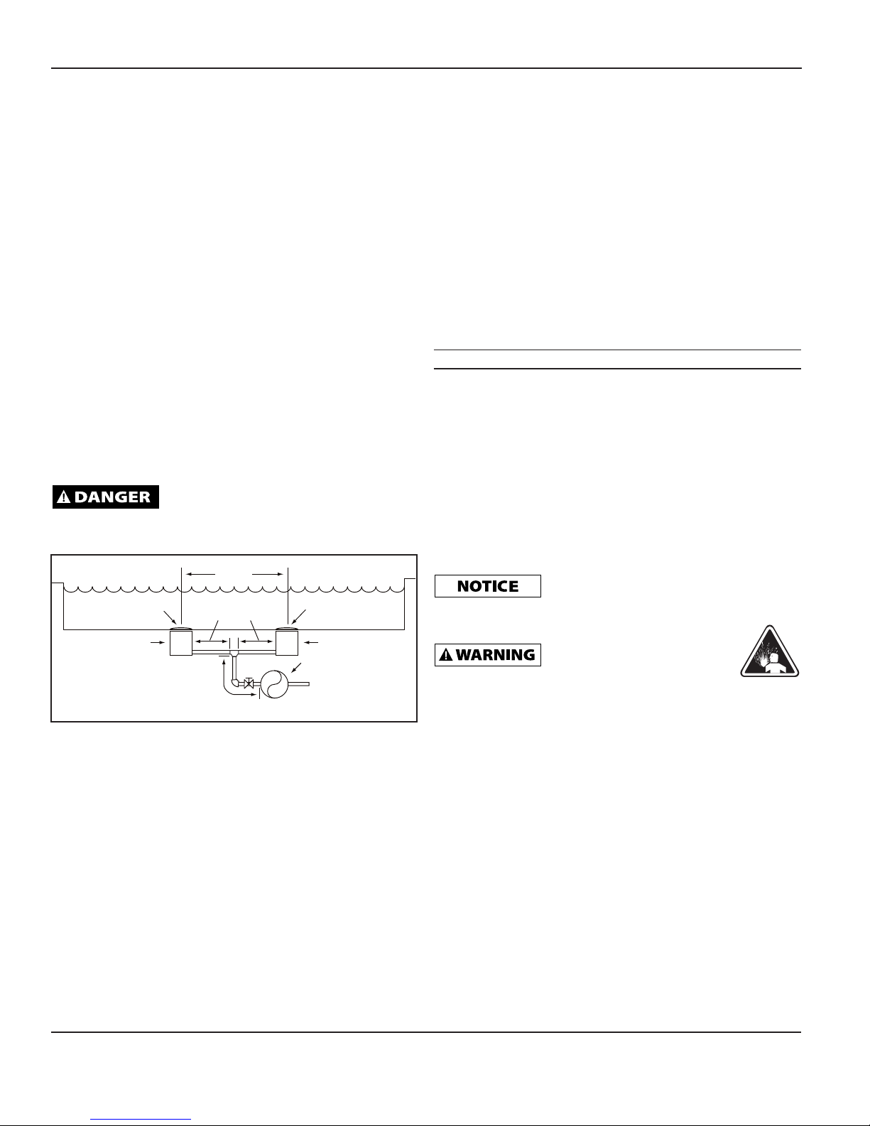
At Least
3 Feet
ANSI/APSP-16 (2011) Certified
Component Anti-Entrapment
Cover/Grate or Suction Fitting
Suction Outlet
(Main Drain)
Valves OK Between
Pump and Tee
Figure A - Outlet Cover Certification
No Valves Between
Tee and Main Drains
ANSI/APSP-16 (2011) Certified
Component Anti-Entrapment
Cover/Grate or Suction Fitting
Suction Outlet
(Main Drain)
Pump
ENTRAPMENT PROTECTION
Refer to ANSI/APSP-7-2006 or latest version for avoiding suction
entrapment. The pump suction must be designed to eliminate the possibility
of suction entrapment or hair entrapment/entanglement.
SUCTION COVERS
Do NOT enter the swimming pool if drain cover is broken or missing. Call
your swimming pool professional immediately to make repairs.
TESTING AND CERTIFICATION
All suction inlet covers must comply with ANSI/APSP-16 (2011)
specifications for suction fittings for use in swimming pools, spas
and whirlpool bathtub applications. The product must be tested for
compliance with the standards and the certification must be included with
the components.
OUTLETS PER PUMP
Provide at least two hydraulically balanced main drains, with covers for
each swimming pool pump suction line. The centers of the main drain's
suction fitting must be at least 3 feet apart (Figure A). The system must
be built so that it cannot operate with the swimming pool pump drawing
water from only one main drain. Two main drains must be connected to the
swimming pool pump whenever it is running. A valve in each suction line
is not allowed.
1. Keep the piping as straight and short as possible, and of suitable size.
2. Do not connect an elbow directly into the pump inlet. A length of
straight pipe will allow proper entry of the water to the pump.
3. Slope horizontal runs upward to the pump to prevent trapping air.
4. Use independent piping supports to alleviate strain on the pump.
5. Keep as much of the suction line as possible below the water level to
reduce priming time.
6. Install valves and unions in the pump suction and return lines to
facilitate servicing. Do not use valves to throttle the pump. Valves are
essential for pump maintenance if the system is installed below deck
level.
INSTALLATION
NOTE:
Refer to ANSI/APSP/ICC-15-2011 or latest version for guidelines on
proper pump selection.
LOCATION
Locate pump as close to swimming pool/spa as possible on a noncombustible surface. Install the pump on a hard, level surface that is dry,
well ventilated and away from direct sunlight. The surrounding area should
provide protection from the elements and ample room for maintenance
and service. Ensure the drainage will flow away from the pump.
Mount pump below water level for easy priming. If the pump must be
located above the filled water level, keep the vertical distance to a minimum.
alignment may cause pump housing failure.
PUMP PLUMBING
Explosion/fire hazard:
adhesive in a well ventilated area.
SOLVENT WELD CONNECTIONS
Use rigid or flexible PVC pipe. Ensure pipe ends are clean and
free of any flash caused by the cutting operation. Use the proper
adhesive for the type of pipe specified.
NOTE: Use an adhesive primer to ensure adhesive joints are
secure. Primers are available with a purple tracer to qualify in areas
where codes specify a primer must be used.
Consider climatic conditions when applying adhesives.
Atmospheric conditions with high humidity will make the adhesive
action of certain glues less effective. Follow the manufacturer’s
instructions.
THREADED CONNECTIONS
Use only plumber’s seal tape or equivalent on threaded plumbing
connections. Other pipe compounds may damage threads. Do not
use silicone or petroleum based compounds. Do not overtighten.
Hand tightening plus 1/2 turn is sufficient.
Excessive pipe strain caused by incorrect
ONLY apply
www.waynepumps.com
3
Page 4
Operating Instructions and Parts Manual
INSTALLATION (ELECTRICAL)
power source before
attempting to install, service, relocate or perform any
maintenance.
NOTE: This pump must be installed by a licensed electrician that
is familiar with swimming pool/spa operations and in accordance
with the NFPA 70 – National Electric Code.
Follow all national and local wiring codes. If unsure of code
requirements consult a professional electrician. Pump must be
permanently connected to a dedicated circuit. If unsure consult
a licensed electrician.
IMPORTANT: Use copper conductors only.
Refer to information on motor nameplates for electrical service
data. Install motors with a fused disconnect switch or a dedicated
circuit breaker. Be sure wire size is sufficient for pump HP and
distance from power source.
Electric shock hazard. Connect
this pump to a properly
grounded GFCI (Ground Fault Circuit Interrupter)
receptacle that is rated for at least 15 amps. Test the
operation of the GFCI receptacle according to the
manufacturer’s recommended intervals.
Disconnect, tag, and lock out
GFCI is required in the circuit. For size of GFCI required and test
procedures for GFCI, see manufacturer’s instructions.
NEVER ground to a gas supply
line, use dedicated grounding
system
.
GFCI tripping indicates an electrical problem. If GFCI trips, determine
the reason for tripping. If you are uncertain, have a l
icensed or certified
electrician that is familiar with swimming pool/spa operations and
in accordance with the NFPA 70 – National Electric Code
inspect
and repair the electrical system.
This pump MUST be installed by
a licensed or certified electrician
that is familiar with swimming pool/spa operations
and in accordance with the NFPA 70 - National Electric
Code.
Verify supply voltage matches the nameplate voltage. Incorrect voltage
can cause fire or seriously damage motor and voids warranty.
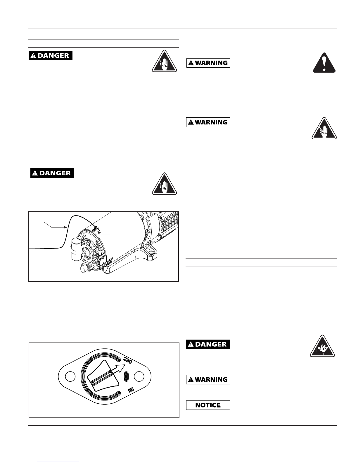
GROUNDING/BONDING
Install, ground, bond and wire motor according to local or National
Electrical Code requirements. Permanently ground the motor. Use ground
terminal provided in the terminal box on the back of the motor. Use size
and type wire required by local codes. Connect motor ground terminal to
electrical service ground.
BONDING WIRE
BONDING LUG
CONNECTION
Figure B - Remove back motor cover
This pump is factory wired for 230 volts. To change the voltage to 115 volts
follow the steps below:
1. Disconnect the pump from power.
2. Remove cover from back of motor to find voltage selector (Figure B).
3. Pull selector knob out.
4. Rotate selector knob to correct voltage setting (Figure C).
5. Push selector knob back in place.
6. Reinstall cover to back of motor.
Bond motor to swimming pool structure. Bonding connects all metal parts
within and around the swimming pool with a continuous wire. Bonding
reduces the risk of current passing between metal objects which could
cause electrical shock. Reference NEC local codes for all wiring standards.
Use a solid copper conductor, size No. 8 AWG or larger. Run wire from
external bonding lug located on top of motor (Figure B) to reinforced rod
or mesh.
OPERATION
Prime pump before attempting to operate. To prime pumps located
above water level, remove strainer cover, fill strainer body with water, then
replace cover. If pump and all piping are located below water level, the
pump will self prime. After pump has been primed, energize motor and
open all suction and discharge line valves. If no flow is observed in five
minutes, stop the motor and re-prime. If the pump fails to operate, check
for air leaks. Refer to troubleshooting section. After about 10 minutes
of operation, check the return fittings for air bubbles. A continuous flow
of air indicates leaks in the suction line. Locate and correct any leaks
immediately.
Suction hazard. Do NOT block
the pump suction with your
body. Failure to do so WILL result in death or serious
bodily injury.
NOTE:
Small children using pool must ALWAYS have close adult supervision.
temperatures, to reduce the risk of fire, do
NOT allow debris or foreign matter to collect around the pump motor.
Allow motor to cool prior to handling or performing maintenance.
Fire and burn hazard. Motor runs at high
Figure C - Voltage selector setting
www.waynepumps.com
Do NOT operate pump without strainer.
Foreign material may interfere with
impeller causing pump to stop.
4
Page 5
WIP SERIES POOL PUMP
OPERATION (CON'T)
The motor is equipped with an internal thermal protection circuit to guard
against overheating. The maximum ambient temperature for motor
operation must not exceed rating on motor model plate.
If the thermal overload protection in the motor trips or if the GFCI trips,
determine the reason and correct the problem before re-starting pump.
Do NOT operate pump with closed or partially
closed suction or discharge valves.
WATER CHEMISTRY
Proper and consistent use of chemicals is necessary to manage a water
system. Chlorine is the most commonly used chemical to provide clean,
sanitary water. Daily administration of dry or liquid chlorine (calcium or
sodium hypochlorite) is essential.
Maintain the correct level of acidity or alkalinity
of the pool water. Readings above pH 7.0 are alkaline. A
pH 7.0 is neutral. Readings below pH 7.0 are acidic. A desirable range is 7.2 to 7.4.
MAINTENANCE
1. Motors are self-lubricating, no additional lubrication is required.
2. Visually inspect motor for blockage of air vents on motor shell. Remove
any debris after shutting off the breaker.
3. Replace worn seals.
Disconnect, tag and lock out
power source before attempting
to install, service, relocate or perform any maintenance.
HAIR AND LINT STRAINER
1. Switch off the power.
2. Close the valves in the suction and return line.
3. Turn strainer cover counterclockwise and remove strainer cover.
4. Lift strainer basket away from the pump.
5. Clean and then reposition the basket into the pump. Take care to seat the
basket properly.
6. Clean the o-ring and re-lubricate with petroleum jelly if necessary.
7. Clean o-ring seats on the cover and pump.
8. Refit the cover and strainer locking ring. Hand tighten only.
9. Open the valves then switch on power to return pump to operation.
WATER LEAKING AROUND MOTOR
A water leak in the area of the motor to pump connection indicates a
mechanical seal failure and a shock hazard. Take pump out of service and
replace seal immediately to avoid damage to other components and to
reduce risk of electric shock. Contact customer service at 1-800-237-0987.
WINTERIZING
Always protect system from freezing temperatures. Drain the system if there
is a possibility of freezing. To drain the system:
1. Units with a filter:
a. Sand filter: Backwash for 3 to 5 minutes and then set dial valve to
winterize position.
b. Cartridge filter: Clean the filter element and store in dry area.
2. Drain system by removing both drain plugs and removing strainer
cover. Removing strainer cover will facilitate draining also. Store drain
plugs in strainer basket, and re-attach strainer cover.
SPRING START-UP
1. Clean and replace drain plugs.
2. Lubricate strainer o-ring with petroleum jelly if needed.
3. Clean o-ring seat, strainer basket and install o-ring in lid.
4. Fill strainer body with water and refer to the Operation Section (Page 4).
CALIFORNIA PROPOSITION 65
This product or its power cord may contain
chemicals, including lead, known to the
State of California to cause cancer and birth defects or other
reproductive harm. Wash hands after handling.
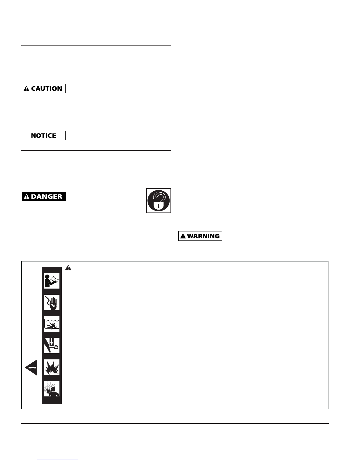
WARNING This is the Safety Alert Symbol. It is used to alert you to potential personal injury hazards. Obey all safety messages
that follow this symbol to avoid possible injury or death.
Avoid Injury. Read and Understand Owner’s Manual Before Operating this Product.
SHOCK HAZARD - Disconnect and lock out power before servicing. GFCI (Ground Fault Circuit Interrupter) required. Unit must be
properly grounded. All electrical components in the system must be bonded together for proper grounding. Location must be wellventilated, out of sun, out of sleeping areas, away from flammable liquids. Keep out of wet areas. Close valves before opening the
strainer cover and drain housing before opening pump housing.
ENTRAPMENT HAZARD - Pumps installed with only one suction outlet can trap, disembowel and drown swimmers. Install pump only
in a pool plumbing system that meets the ASME/ANSI A112.19.8 requirements. Two suction outlets at least 3 feet apart are required.
All suction fittings must be agency approved for anti-entrapment, anti-hair entanglement, correctly installed and not damaged. Do not
use pool if drain or outlet covers are broken or missing.
MECHANICAL HAZARD - Contains moving parts. Switch off and lock-out power before working on pump. Pump designed for
WARNING
permanent pool applications only. Any other use could be hazardous.
EXPLOSION HAZARD - Use water to pressure test. Compressed air could cause pump to explode violently. Securely tighten and
center the basket clamp ring prior to pressure testing system. Bleed off all trapped air in system before pressure testing. Never use air
or gas to detect leaks. Do not use a leak test pressure greater than 25 PSI higher pressure will permanently damage pump. Use only
piping and fittings that are designed for pools. Never leave water in the pump or filter during freezing weather. Ice will cause housing
to break.
WATER UNDER PRESSURE - Water under pressure could cause serious bodily injury. Keep people and pets away from fountains,
jets and outlets while filling pool or spa.
www.waynepumps.com
5
Page 6
Troubleshooting and Replacement Parts
Electrocution hazard! Pump can start automatically. Disconnect
Troubleshooting Chart
Symptoms Possible Cause(s) Corrective Action
the power before attempting any repairs. Failure to follow these
instructions WILL result in serious injury or death.
Motor does not start 1. Disconnect switch or circuit breaker in OFF position
2. Fuses blown or thermal overload open
3. Disconnected or defective wiring
Motor does not reach full
speed
Motor overheats
(protector trips)
Pump does not deliver
water
Noisy pump and motor 1. Plugged basket in skimmer or hair in lint strainer
Low pump capacity 1. Valve in suction or discharge line partly closed
Leakage of water at shaft 1. Shaft seal requires replacement 1. Replace seal
High pump pressure 1. Discharge valve closed
Air bubbles collecting in
strainer
1. Low voltage
2. Motor windings connected for wrong voltage
1. Low voltage
2. Motor windings connected for wrong voltage
3. Inadequate ventilation
1. Pump is not primed
2. Suction or discharge valve is closed
3. Leakage or air into suction system
4. Hair and lint strainer is full
5. Water level in swimming pool is too low
2. Valve in suction line partly closed
3. Vacuum hose plugged or too small
4. Pump not supported properly
2. Suction or discharge line too small
3. Plugged basket in skimmer or hair in lint strainer
4. Dirty filter
2. Return lines too small
3. Dirty filter
1. Leakage of air into suction line at connections or valve
stem
2. Strainer cover leaking
3. Restriction in suction line
4. Low water level in swimming pool
1. Reset breaker
2. Check voltage
3. Check wiring
1. Check voltage settings
2. Inspect motor voltage selector
1. Check voltage settings
2. Inspect motor voltage selector
3. Remove obstructions around pump
1. Prime pump as directed in the “Operation” section
2. Open the valve
3. Eliminate leaks in suction line
4. Clean strainer (see maintenance section)
5. Fill swimming pool to proper level
1. Clean skimmer and lint strainer
2. Open all valves during operation
3. Check for collapsed hose and replace
4. Add additional supports
1. Open all valves
2. Use larger supply line
3. Clean skimmer and lint strainer
4. Clean filter (see filter manual)
1. Always run with valves open
2. Replace with larger lines
3. Clean filter (see filter manual)
1. Eliminate leaks in suction line
2. Remove and clean o-ring
3. Increase suction line size
4. Fill swimming pool to correct level
For Replacement Parts or
Technical Assistance, call
1-800-237-0987
Please provide following information:
- Model number
- Serial number (if any)
- Part description and number as shown in parts list
Address parts correspondence to:
WAYNE Water Systems
101 Production Drive
Harrison, OH 45030 U.S.A.
Ref. No. Description Order No. Quantity
1 Strainer Cover and Gasket 69010-001 1
2 Strainer 28477-001 1
www.waynepumps.com
1
2
6
Page 7

WIP SERIES POOL PUMP
Limited Warranty
For one year from the date of purchase, WAYNE Water Systems Division ("WAYNE Pumps") will repair or re place, at its
option, for the original purchaser any part or parts of its Water Pumps (“Product”) found upon examination by WAYNE to be
defective in materials or work man ship. Please call WAYNE Pumps (1-800-237-0987) for instructions. Be pre pared to provide
the model number and the serial number when exercising this warranty. All transportation charges on Products or parts
submitted for repair or replacement must be paid by purchaser.
This Limited Warranty does not cover Products which have been damaged as a result of accident, abuse, misuse, neglect,
improper application, improper maintenance, or failure to operate in accordance with WAYNE Pumps' written instructions.
THERE IS NO OTHER EXPRESS WARRANTY. IMPLIED WARRANTIES, IN CLUD ING THOSE OF MER CHANT ABIL ITY AND FITNESS FOR A PARTICULAR PUR POSE, ARE LIMITED TO ONE YEAR FROM THE DATE OF PURCHASE.
THIS IS THE EXCLUSIVE REM E DY AND ANY LIABILITY FOR ANY AND ALL INDIRECT OR CONSEQUENTIAL
DAM AG ES OR EXPENSES WHATSOEVER IS EXCLUDED.
Some states do not allow limitations on how long an implied warranty lasts, or do not allow the exclusions or limitations of
incidental or consequential damages, so the above lim i ta tions might not apply to you. This limited war ran ty gives you specific
legal rights, and you may also have other legal rights which vary from state to state.
In no event, whether as a result of breach of contract warranty, tort (in clud ing negligence) or otherwise, shall WAYNE Pumps
or its suppliers be liable for any special, consequential, incidental or penal damages including, but not limited to loss of profit
or revenues, loss of use of the products or any associated equipment, damage to associated equip ment, cost of capital, cost
of substitute products, facilities, services or replacement power, downtime costs, or claims of buyer’s cus tom ers for such
damages.
You MUST retain your purchase receipt along with this form. In the event you need to exercise a warranty claim, you MUST
send a copy of the purchase receipt along with the material or correspondence. Please call WAYNE Pumps (800-237-0987)
for return authorization and instructions.
DO NOT MAIL THIS FORM TO WAYNE PUMPS. Use this form only to maintain your records.
MODEL NO._______________ SERIAL NO.__________________________ DATE_____________
ATTACH YOUR RECEIPT HERE
www.waynepumps.com
7
Page 8

Sortie d'aspiration
(Drain principal)
Sortie d'aspiration
(Drain principal)
Vannes OK entre
la pompe et le T
Pompe
0,9 m minimum
(3 pieds)
Composant certifié ANSI/APSP-16
(2011) : couvercle/grille ou raccord
d'aspiration anti-piégeage
Aucune vanne entre le T et
les drains principaux
Composant certifié ANSI/APSP-16
(2011) : couvercle/grille ou raccord
d'aspiration anti-piégeage
POMPE DE PISCINE
MODE D'EMPLOI ET LISTE DES PIÈCES DÉTACHÉES
MODÈLES : WIP150 / WIP100 / WIP90 (CONFORMES À LA NORME 20 DE CALIFORNIE)
LIRE, S’ASSURER DE COMPRENDRE ET SUIVRE TOUTES LES INSTRUCTIONS DE CE MANUEL - NE PAS JETER.
Le non-respect de ces instructions pourrait entraîner des dommages matériels, de graves blessures ou la mort.
Installateur : Veuillez laisser ce manuel à la disposition du propriétaire.
INSTRUCTIONS DE DÉMARRAGE RAPIDE
ÉTAPE 1 : VÉRIFICATION DU CONTENU DU PAQUET
ÉTAPE 4 : MÉTALLISATION
SÉRIE WIP
POMPE DE PISCINE
ÉVACUATION
ENTRÉE
D'ASPIRATION
ÉTAPE 2 : VÉRIFICATION DE LA TENSION DE LA POMPE EXISTANTE
115 V
Tout le travail de câblage et
d’entretien doit être effectué par un
(1) POMPE
(1) COUVERCLE
(1) JOINT
D'ÉTANCHÉITÉ
(1) FILTRE
électricien qualifié. Vous devez faire
correspondre le voltage de notre
pompe avec l'alimentation électrique
existante.
230 V
ÉTAPE 3 : COMMENT CHANGER LE SÉLECTEUR DE TENSION
Cette pompe est câblée en usine pour 230 volts. Pour passer à une
tension de 115 volts, suivre les étapes suivantes :
1. Couper l’alimentation électrique de la pompe.
2. Retirer le couvercle à l'arrière du moteur pour trouver le sélecteur
de tension.
3. Tirer sur le bouton de sélection.
4. Tourner le bouton de sélection jusqu’au réglage
de tension adapté.
5. Repousser le bouton de sélection en place.
6. Réinstaller le couvercle à l'arrière du moteur.
Utiliser un conducteur de connexion en
cuivre massif dont la taille minimale ne doit
pas être inférieure à 8 AWG (8,4 mm2).
ÉTAPE 5 : PLOMBERIE DE LA POMPE
Avant d’entreprendre l'installation d'une quelconque pompe de piscine,
lire et s’assurer de comprendre TOUTES les directives (ANSI/APSP/ICC15 2011) concernant l'aspiration et l'installation. Le tuyau d'aspiration doit
être aussi large ou plus large que le tuyau d'évacuation. Éviter d'utiliser un
tuyau d'aspiration plus petit que le raccord de pompe.
NE PAS entreprendre d’installer une pompe de
piscine sans avoir lu et compris les normes,
directives et réglementations suivantes : ANSI/APSP-16 (2011); ANSI/
APSP-7 (2006); ANSI/ASME A112.19.17 (2010); ASTM F2387 (2004);
Virginia Graeme Baker Pool and Spa Safety Act (2007) (Loi sur la sécurité
des piscines et spas) ; publication du CPSC dénommée Guidelines for
Entrapment Hazards (Directives contre les risques de piégeage); ainsi
que toutes les normes ultérieures et lois des différents états.
NE PAS entrer dans une piscine si un couvercle de drain est brisé ou
absent. Fermer la piscine ou le spa. Appelez immédiatement votre piscinier
pour faire effectuer les réparations. Amorcer la pompe avant de la faire
fonctionner. Pour amorcer les pompes situées au-dessus du niveau de
l'eau, retirer le couvercle du filtre, remplir d'eau le corps de l'épurateur,
puis remettre le couvercle en place. Si la pompe et toute la tuyauterie sont
situées en-dessous du niveau d'eau, la pompe s'auto-amorcera.
Une fois la pompe amorcée, stimuler le moteur et ouvrir toutes les vannes
de la conduite d'aspiration et de refoulement. Si aucun débit n'est observé
dans les cinq minutes, arrêter le moteur et réamorcer. Si la pompe ne
fonctionne pas, rechercher des fuites d'air. Se reporter à la section
dépannage.
SÉLECTEUR DE TENSION
© 2012,
WAYNE/Scott Fetzer Company.
Après environ 10 minutes de fonctionnement, vérifier les raccords
d'évacuation pour déceler toute bulle d'air. Un flux continu d'air indique
des fuites dans la conduite d'aspiration. Localiser et corriger toute fuite
immédiatement.
POUR DES INSTRUCTIONS SUPPLÉMENTAIRES, LES EXIGENCES DE
SÉCURITÉ, LES NORMES ET LA RÉGLEMENTATION CONCERNANT
L’INSTALLATION, SE RÉFÉRER AUX INFORMATIONS CONTENUES
DANS CE MANUEL.
Pour des renseignements sur les pièces, les produits et l’entretien,
visiter www.waynepumps.com
Page 9

POMPE DE PISCINE
MODE D'EMPLOI ET LISTE DES PIÈCES DÉTACHÉES
MODÈLES : WIP150 / WIP100 / WIP90 (CONFORMES À LA NORME 20 DE CALIFORNIE)
LIRE, S’ASSURER DE COMPRENDRE ET SUIVRE TOUTES LES INSTRUCTIONS DE CE MANUEL - NE PAS JETER.
Le non-respect de ces instructions pourrait entraîner des dommages matériels, de graves blessures ou la mort.
Installateur : Veuillez laisser ce manuel à la disposition du propriétaire.
INSTRUCTIONS D’INSTALLATION ET MODE D'EMPLOI
DESCRIPTION
Les pompes de piscine font partie du système de filtration d'eau des
piscines. Ces pompes font circuler l'eau des piscines enterrées ou
hors-sol.
DÉBALLAGE
Inspecter cet appareil avant de l'utiliser. Il arrive parfois que les
installées de façon permanente. Si ceci est spécifié,
la pompe peut être utilisée avec les jacuzzis et les spas. Ne pas l’utiliser avec
les piscines démontables. Une piscine installée de façon permanente est
construite dans ou sur le sol ou encore à l'intérieur d'un bâtiment de telle
sorte qu'elle ne peut pas être facilement démontée en vue de son stockage.
Une piscine démontable est construite de manière à être facilement
démontée en vue de son stockage et remontée dans son intégrité d'origine
produits soient endommagés durant le transport. Si la pompe
ou les composants sont endommagés, contacter le service
clientèle au 1-800-237-0987.
DIRECTIVES DE SÉCURITÉ
Pour aider à reconnaître cette information, consulter les
uniquement de l'eau claire. Ne pas pomper
de liquide inflammable ou explosif tel que l'essence, le mazout, le
kérosène, etc. Ne pas utiliser dans un environnement inflammable et/
ou explosif. Le non-respect de ces instructions pourrait entraîner des
blessures corporelles et/ou des dommages matériels.
mots-indicateurs et classifications de dangers qui suivent.
dangers possibles de blessures corporelles. Respecter tous les messages de
sécurité qui suivent ce symbole pour éviter toutes blessures possibles
Ceci est le symbole d'alerte de sécurité. Il est utilisé pour vous prévenir des
.
certifié connaissant le fonctionnement des piscines/
spa conformément aux directives du Code électrique
national NFPA 70.
Danger indique une situation dangereuse
imminente qui, si elle n'est PAS évitée,
MÈNERA à la mort ou à des blessures graves.
Avertissement indique une situation
i hasardeuse potentielle qui peut résulter
en perte de vie ou blessures graves.
Attention indique une situation potentiellement
dangereuse qui, si elle n’est PAS évitée,
POURRAIT entraîner des lésions corporelles mineures ou modérées
Avis indique des informations importantes
à respecter. Le NON-RESPECT de ces
instructions POURRAIT endommager l’équipement.
REMARQUE: Remarque indique une information qui exige une attention
particulière.
températures élevées. Ne pas laisser de feuilles, de débris
ou de matières étrangères s’accumuler autour du moteur
de la pompe. Garder les ouvertures d'aération ouvertes.
Laisser le moteur refroidir avant de le manipuler. Tenir éloignés les
liquides inflammables.
SIGLES ET DÉFINITIONS
ASHRAE : American Society of Heating, Refrigeration and Air
.
Conditioning Engineers (Société américaine des ingénieurs thermiciens)
ANSI: American National Standards Institute (Institut américain
des normes)
APSP: The Association of Pool and Spa Professionals
(Association des professionnels des piscines et spas)
ASME: American Society of Mechanical Engineers (Société
CONSIGNES GÉNÉRALES DE SÉCURITÉ
GÉNÉRALITÉS SUR LA SÉCURITÉ
1. Lire attentivement le(s) manuel(s) inclus avec ce
produit. Bien se familiariser avec les commandes et
la bonne utilisation de l’équipement. Suivre toutes
les instructions.
2. Seules les personnes bien familiarisées avec ces consignes
de sécurité d'utilisation doivent être autorisées à utiliser cet
appareil.
Ne PAS laisser les enfants utiliser
cette pompe.
3. Porter en tout temps des lunettes de sécurité
avant d’effectuer toute manoeuvre sur une
pompe.
4. L’appareil DOIT être branché sur un circuit
disposant d'un disjoncteur de fuite de terre correctement
installé. Consulter un électricien qualifié pour une installation
en bonne et due forme d’un circuit avec disjoncteur de fuite
de terre.
américaine des ingénieurs mécaniciens)
CPSC: Consumer Products Safety Commission (Commission
pour la sécurité des produits de consommation)
NEC: National Electric Code (Code électrique national)
NFPA: National Fire Protection Association (Association
nationale de protection contre l'incendie)
NE PAS utiliser la pompe si une partie
quelconque du boîtier est fissurée, brisée ou
manquante.
Risque de secousse
électrique. COUPER
LE COURANT avant tout entretien
ou réparation. Installer un cadenas
fermé ou une étiquette pour éviter tout
rétablissement inattendu de l'électricité.
Cet appareil n'est pas conçu pour
être utilisé comme pompe de
puisard, dans les fosses septiques ou dans les enceintes
souterraines. Ne jamais l’utiliser dans des endroits
dangereux ou explosifs.
Cette pompe est conçue pour les piscines
Risque d'explosion ! Pomper
Cette pompe doit être installée
par un électricien agréé ou
Risque d’incendie et de brûlure !
Les moteurs tournent à des
SÉRIE WIP
POMPE DE PISCINE
.
RAPPEL : Conserver votre preuve d’achat datée aux fins de la garantie ! Fixer le reçu à ce manuel ou le ranger en lieu sûr.
Pour des renseignements sur les pièces, les produits et l’entretien,
© 2012,
WAYNE/Scott Fetzer Company.
visiter www.waynepumps.com
9 Fr
Page 10

POMPE DE PISCINE DE LA SÉRIE WIP
DIRECTIVES DE SÉCURITÉ POUR LES PISCINES
SURVEILLANCE PAR UN ADULTE RESPONSABLE
Une surveillance constante par un adulte responsable est obligatoire
autour de la piscine ou du spa. Toujours surveiller les enfants autour
des piscines et des spas. Ne jamais laisser un enfant jouer de sorte qu’il
puisse approcher les cheveux du couvercle du drain.
Ne PAS laisser les enfants
utiliser cette pompe.
Ne PAS installer de multiples pompes sur un même circuit hydraulique.
La pompe n'est pas conçue pour accepter le débit de sortie d'une autre
pompe. Ne PAS laisser l'eau refluer dans la pompe. De l'eau coulant dans
l'évacuation et sortant par la sortie d'aspiration pendant une situation
problématique peut amener le moteur à fonctionner en sens inverse. Ne
JAMAIS entreprendre de démarrer la pompe si l'arbre d'entraînement
tourne sous l'effet de l'action d’une turbine hydraulique; ceci POURRAIT
amener la pompe à fonctionner en sens inverse et endommager les
composantes internes.
DRAINS, RACCORDS D'ASPIRATION ET JETS
1. Ne laisser personne, enfant ou adulte, jouer à proximité de ou s'asseoir
sur une quelconque sortie d'aspiration (drain) ou un quelconque raccord
d'aspiration mural !
2. Ramener les cheveux longs en queue de cheval ou sous un bonnet de
bain.
3. Retirer vos bijoux avant d'entrer dans la piscine.
4. Demander à un professionnel agréé d'inspecter toutes les sorties
d'aspiration.
5. S’assurer que les couvercles de drain sont certifiés ANSI/APSP-16
(2011) et que les raccords d'aspiration muraux sont à fermeture
verrouillage automatique.
6. Remplacer tout couvercle de drain brisé, manquant ou non certifié par un
couvercle certifié ANSI/APSP-16 (2011).
DANGERS ÉLECTRIQUES
Un électricien agréé, expérimenté en piscines et spas doit inspecter
votre équipement pour s'assurer que tout est correctement mis à la terre,
métallisé et protégé par des circuits de disjoncteur de fuite à la terre,
conformément à l'Article 680 du Code électrique national.
INSTALLATIONS À L'INTÉRIEUR
Les piscines et spas intérieurs doivent être conformes à la norme ANSI/
ASHRAE 62-2001 pour garantir une ventilation adéquate et une utilisation
sans risque.
Ne PAS entrer dans la piscine si le couvercle
du drain est brisé ou manquant. Fermer la
piscine ou le spa. Appeler immédiatement votre piscinier pour faire
effectuer les réparations.
0,9 m minimum
(3 pieds)
Composant certifié ANSI/APSP-16
(2011) : couvercle/grille ou raccord
d'aspiration anti-piégeage
Sortie d'aspiration
(Drain principal)
Figure A - Certification de couvercle de sortie
www.waynepumps.com
Aucune vanne entre le T et
les drains principaux
Vannes OK entre
la pompe et le T
Composant certifié ANSI/APSP-16
(2011) : couvercle/grille ou raccord
d'aspiration anti-piégeage
Sortie d'aspiration
(Drain principal)
Pompe
PROTECTION CONTRE LE PIÉGEAGE
Se reporter à la norme ANSI/APSP-7-2006 ou à la version la plus récente
pour éviter un piégeage par aspiration. L'aspiration de la pompe doit
être conçue pour éliminer la possibilité de piégeage par aspiration ou de
piégeage/emmêlement des cheveux.
COUVERCLES D'ASPIRATION
NE PAS entrer dans la piscine si un couvercle de drain est brisé ou
manquant. Appelez immédiatement votre piscinier pour faire effectuer les
réparations.
TEST ET CERTIFICATION
Tous les couvercles d'entrée d'aspiration doivent se conformer aux
spécifications ANSI/APSP-16 (2011) pour les raccords d'aspiration à
utiliser dans les piscines, spas et baignoires à remous. Le produit doit être
testé pour conformité aux normes et la certification doit être incluse avec
les composants.
SORTIES PAR POMPE
Fournir au moins deux drains principaux hydrauliquement équilibrés, avec
couvercles pour chaque conduite d'aspiration de pompe de piscine. Les
centres de chaque raccord d'aspiration principal doivent être séparés d'au
moins 0,9 m (3 pi) l'un de l'autre (Figure A). Le système doit être bâti de
manière à ce qu'il ne puisse pas fonctionner si la pompe aspire de l'eau
par un seul drain. Les deux drains principaux doivent être connectés à
la pompe de piscine chaque fois qu'elle fonctionne. L'installation d'une
vanne sur chaque conduite d’aspiration n'est pas permise.
1. Installer une tuyauterie aussi rectiligne et courte que possible, et d'une
taille adaptée.
2. Ne pas brancher de coude directement à l'entrée de la pompe. Une
longueur de tuyau droit permettra une entrée adéquate de l'eau dans
la pompe.
3. Une dénivellation horizontale remonte vers la pompe pour éviter
d'emprisonner l'air.
4. Utiliser des supports de tuyauterie indépendants pour atténuer la
tension sur la pompe.
5. Conserver autant que possible la conduite d'aspiration en-dessous du
niveau d'eau pour réduire le temps d'amorçage.
6. Installer les vannes et les raccords dans les conduits d'aspiration et
de refoulement de la pompe pour faciliter l'entretien. Ne pas utiliser de
vannes pour contrôler le débit de la pompe. Les vannes sont
essentielles pour l'entretien de la pompe si le système est installé en
dessous du pourtour de la piscine.
INSTALLATION
REMARQUE : Se référer à la norme ANSI/APSP/ICC-15-2011 ou
à la version la plus récente pour bien choisir la pompe.
EMPLACEMENT
Placer la pompe aussi près que possible de la piscine/du spa sur une
surface non combustible. Installer la pompe sur une surface dure, plane,
au sec, bien ventilée et protégée de la lumière directe du soleil. La zone
environnante doit fournir une protection contre les éléments et un ample
espace permettant l'entretien et la réparation. S’assurer que le drainage
s'écoulera à partir de la pompe.
Monter la pompe sous le niveau d'eau pour faciliter l'amorçage. Si la pompe
doit être placée au-dessus du niveau d'eau rempli, maintenir la distance
verticale à un minimum.
10 Fr
Page 11

Mode d'emploi et liste des pièces détachées
exercée par un mauvais alignement des
tuyaux peut provoquer une rupture du carter de pompe.
Une contrainte excessive sur la pompe
TUYAUTERIE DE LA POMPE
Risque d'explosion/d’incendie :
N'utiliser des adhésifs/colles que
dans un endroit bien ventilé.
RACCORDS SOUDÉS À L'AIDE DE SOLVANTS
Utiliser un tuyau en PVC rigide ou souple. S’assurer que les
extrémités du tuyau sont propres et exemptes de tout éclat causé
par l'opération de découpe. Utiliser l'adhésif approprié pour le type
de tuyau spécifié.
REMARQUE : Utiliser un apprêt pour adhésif pour s’assurer que
les collages des joints sont solides. Certains apprêts possèdent
un traceur mauve d'éligibilité dans les zones où la règlementation
spécifie qu'un apprêt doit être utilisé.
Tenir compte des conditions climatiques lors de l'application
d'adhésifs/colles. Des conditions atmosphériques avec une
humidité élevée rendront l'action adhésive de certaines colles
moins efficace. Suivre les indications du fabricant.
RACCORDS FILETÉS
Utiliser seulement un ruban d'étanchéité de plombier (ou
l'équivalent) sur les raccords filetés. D'autres composés pour tuyau
pourraient endommager les filetages. Ne pas utiliser de silicone ou
de composés à base de pétrole. Ne pas trop serrer. Un serrage à
la main plus 1/2 tour est suffisant.
INSTALLATION (ÉLECTRIQUE)
verrouiller la source
d'alimentation avant d'installer, de réparer, ou de
déplacer l’appareil, ou encore avant d'effectuer une
opération d’entretien.
REMARQUE : Cette pompe doit être installée par un électricien
agréé connaissant le fonctionnement des piscines/spa
conformément aux directives du Code électrique national NFPA 70.
Respecter tous les codes locaux et nationaux concernant le
câblage. Si vous n'êtes pas certain des exigences du code,
contactez un électricien professionnel. La pompe doit être
branchée en permanence à un circuit dédié. En cas de doute,
contacter un électricien agréé.
IMPORTANT :
Se reporter aux informations indiquées sur les plaques
signalétiques du moteur pour les données d'entretien électrique.
Installer les moteurs avec un interrupteur sectionneur à fusible ou
un disjoncteur dédié. S’assurer que la taille du fil est suffisante
pour la puissance de la pompe et la distance par rapport à la
source de courant.
Risque de secousse électrique.
Raccorder cette pompe
à un réceptacle de disjoncteur de fuite de terre
correctement installé pour une intensité nominale
minimum de 5 A. Tester le fonctionnement du
disjoncteur de fuite de terre conformément aux
intervalles recommandés par le fabricant.
Débrancher, étiqueter et
Utiliser uniquement des fils conducteurs en cuivre.
FIL DE
CONNEXION
Figure B - Retirer le couvercle arrière du moteur
RACCORDEMENT
DE LA VIS DE
CONNEXION
Cette pompe est câblée en usine pour 230 volts. Pour passer à une tension
de 115 volts, suivre les étapes suivantes :
1. Couper l'alimentation électrique de la pompe.
2. Retirer le couvercle de l'arrière du moteur pour trouver le sélecteur de
tension (figure B).
3. Tirer sur le bouton de sélection.
4. Tourner le bouton de sélection jusqu’au réglage de tension adapté
(Figure C).
5. Repousser le bouton de sélection en place.
6. Réinstaller le couvercle à l'arrière du moteur.
Figure C - Réglage du sélecteur de tension
Le circuit doit comporter un disjoncteur de fuite de terre. Pour la
taille du disjoncteur de fuite à la terre et les procédures de test du
disjoncteur de fuite à la terre, voir les directives du fabricant.
sur une canalisation de gaz;
utiliser un système de mise à la terre dédié.
Ne JAMAIS mettre à la terre
Le déclenchement du disjoncteur de fuite de terre indique
l'existence d'un problème électrique. Si le disjoncteur de fuite de terre se
déclenche, en déterminer la raison. Si vous n'êtes pas certain de la cause,
demandez à un électricien agréé ou certifié connaissant le fonctionnement
des piscines/spa, conformément aux directives du Code électrique
national - NFPA 70 d'inspecter et de réparer le système électrique.
Cette pompe DOIT être installée
par un électricien agréé ou
certifié connaissant le fonctionnement des piscines/
spa conformément aux directives du Code électrique
national - NFPA 70.
S'assurer que la tension de l'alimentation correspond à celle indiquée sur
la plaque signalétique. Une tension incorrecte peut provoquer un incendie
ou endommager gravement le moteur tandis qu’elle annule la garantie.
MISE À LA TERRE/MÉTALLISATION
L'installation, la mise à la terre, la métallisation et le câblage du moteur
doivent être réalisés conformément aux exigences du Code électrique
local ou national. Le moteur doit être relié à la terre en permanence.
www.waynepumps.com
11 Fr
Page 12

POMPE DE PISCINE DE LA SÉRIE WIP
Utiliser la borne de mise à la terre présente dans la boîte de la borne
à l'arrière du moteur. Utiliser un fil de taille et de type conforme aux
exigences des codes locaux. Raccorder la borne de mise à la terre du
moteur à la mise à la terre du réseau électrique.
Relier le moteur à la structure de la piscine. La métallisation relie toutes les
pièces métalliques au sein et autour de la piscine avec un câble continu.
La métallisation réduit le risque de laisser passer du courant entre des
objets métalliques, ce qui pourrait provoquer un choc électrique. Se
référer aux codes NEC locaux à propos des normes de câblage. Utiliser
un conducteur en cuivre massif de taille nº 8 AWG ou supérieure. Tirer le
câble depuis la vis extérieure de la borne située sur le moteur (Figure B)
jusqu’à une tige ou maille renforcée.
FONCTIONNEMENT
Amorcer la pompe avant de la faire fonctionner. Pour amorcer les pompes
situées au-dessus du niveau d'eau, retirer le couvercle du filtre, remplir
d'eau le corps du filtre, puis remettre le couvercle en place. Si la pompe
et toute la tuyauterie sont situées en-dessous du niveau d'eau, la pompe
s'auto-amorcera. Une fois la pompe amorcée, stimuler le moteur et ouvrir
toutes les vannes de la conduite d'aspiration et de refoulement. Si aucun
débit n'est observé dans les cinq minutes, arrêtez le moteur et réamorcez.
Si la pompe ne fonctionne pas, rechercher des fuites d'air. Se reporter à la
section dépannage. Après environ 10 minutes de fonctionnement, vérifier
les raccords d'évacuation pour déceler toute bulle d'air. Un flux continu
d'air indique des fuites dans la conduite d'aspiration. Localiser et corriger
toute fuite immédiatement.
Risque d'aspiration Ne PAS
bloquer l'aspiration de la
pompe en vous plaçant devant. Le non-respect de cet
avertissement ENTRAÎNERAIT la mort ou de graves
blessures corporelles.
REMARQUE : Les jeunes enfants utilisant la piscine doivent
TOUJOURS être sous la surveillance attentive d'un adulte.
fonctionne à des températures élevées; pour
réduire le risque d'incendie, ne PAS laisser de débris ou de matières
étrangères s'accumuler autour du moteur de la pompe. Laisser
le moteur refroidir avant de le manipuler ou de procéder à son
entretien.
filtre. Des matières étrangères peuvent
entraver le fonctionnement de l'impulseur et provoquer l'arrêt de la
pompe.
Risque d’incendie et de brûlure. Le moteur
Ne PAS faire fonctionner la pompe sans
FONCTIONNEMENT
Le moteur est doté d'un circuit interne de protection thermique qui
le protége de la surchauffe. La température ambiante maximum de
fonctionnement du moteur ne doit pas dépasser la température indiquée
sur la plaque signalétique du moteur. Si la protection contre la surcharge
thermique du moteur se déclenche ou si le disjoncteur de fuite à la terre
se déclenche, en déterminer la raison et corriger le problème avant de
redémarrer la pompe.
Ne PAS faire fonctionner la pompe avec des
vannes d'aspiration ou d’évacuation fermées
ou partiellement fermées.
CHIMIE DE L'EAU
L'entretien d'un système d'eau nécessite l'utilisation appropriée et
cohérente de produits chimiques. Le chlore est le produit chimique le plus
couramment utilisé pour fournir une eau propre et salubre. L'administration
quotidienne de chlore sec ou liquide (hypochlorite de calcium ou de
sodium) est essentielle.
Maintenir un niveau correct d'acidité ou d'alcalinité de
l'eau de piscine. Les valeurs de pH supérieures à pH 7,0
sont basiques. Un pH de 7,0 est neutre. Les valeurs de pH inférieures à 7,0 sont
acides. La fourchette souhaitable est de 7,2 à 7,4.
ENTRETIEN
1. Les moteurs sont autolubrifiants : aucune lubrification supplémentaire
n'est nécessaire.
2. Inspecter visuellement le moteur pour déceler toute obstruction des
prises d'air sur la coque du moteur. Retirer les débris après avoir
coupé le disjoncteur.
3. Remplacer les joints usagés.
Débrancher, étiqueter et
verrouiller la source
d'alimentation avant d'installer, de réparer, ou de
déplacer l’appareil, ou encore avant d'effectuer une
opération d’entretien.
FILTRE À CHEVEUX ET PELUCHES
1. Couper l'alimentation.
2. Fermer les vannes des conduits d'aspiration et de refoulement.
3. Tourner le couvercle du filtre dans le sens contraire des aiguilles d'une
montre et le retirer.
4. Soulever le panier du filtre et le retirer de la pompe.
5. Nettoyer puis repositionner le panier dans la pompe. Prendre soin de
placer le panier correctement.
6. Nettoyer le joint torique et le lubrifier de nouveau avec de la vaseline si
nécessaire.
7. Nettoyer les emplacements du joint torique sur le couvercle et sur le filtre.
8. Remettre en place le couvercle et l'anneau de verrouillage du filtre.
Resserrer uniquement à la main.
9. Ouvrir les vannes, puis rétablir le courant pour remettre la pompe en
marche.
FUITE D'EAU AUTOUR DU MOTEUR
Une fuite d'eau dans le secteur du raccord entre le moteur et la pompe
indique une défaillance mécanique du joint d'étanchéité et un risque de
choc électrique. Mettre la pompe hors service et remplacer immédiatement
le joint pour éviter que d'autres composants ne soient endommagés, et
pour réduire le risque de choc électrique. Contacter le service clientèle au
1-800-237-0987.
HIVÉRISATION
Toujours protéger le système contre le gel. Vidanger le système en cas de
risque de gel. Pour vidanger le système :
1. Appareils avec un filtre :
a. Filtre à sable : Laver à contre-courant pendant 3 à 5 minutes et
mettre ensuite les vannes en position d'hivernage
b. Filtre à cartouche : Nettoyer l'élément filtrant et le stocker dans un
endroit sec.
2. Purger le système en retirant les deux bouchons de drainage et en
retirant le couvercle du filtre. Le fait de retirer le couvercle du filtre
facilitera également la vidange. Ranger les bouchons de drainage dans
le panier du filtre et réinstaller le couvercle du filtre.
REMISE EN ROUTE AU PRINTEMPS
1. Nettoyer et remettre en place les bouchons de drainage.
2. Lubrifier le joint torique du filtre avec de la vaseline si nécessaire.
3. Nettoyer le siège du joint torique, le filtre et son panier, puis installer le
joint torique dans le couvercle.
4. Remplir d'eau le corps du filtre et se reporter à la section Mode
d’emploi (page 13).
www.waynepumps.com
12 Fr
Page 13

AVERTISSEMENT Ceci représente le symbole d'alerte de sécurité. Il est utilisé pour vous prévenir des risques possibles de blessures
corporelles. Respecter tous les messages de sécurité qui suivent ce symbole pour éviter tout risque de blessure ou la mort.
Évitez les blessures. Lire et s’assurer de comprendre le Manuel du propriétaire avant de faire fonctionner ce produit.
RISQUE D’ÉLECTROCUTION - Couper et neutraliser l’alimentation avant l’entretien. Disjoncteur de fuite de terre requis. L'appareil doit être
correctement relié à la terre. Tous les composants électriques du système doivent être correctement mis au contact les uns avec les autres
pour une mise à la terre correcte. L'emplacement choisi doit être bien ventilé, ne pas être exposé à la lumière directe du soleil, et se trouver à
distance des zones de repos et des liquides inflammables. Garder à l'abri des endroits humides. Fermer les vannes avant d'ouvrir le couvercle
du filtre, et le carter du drain avant d'ouvrir le carter de la pompe.
RISQUE DE PIÉGEAGE - Les pompes mises en place avec une seule sortie d'aspiration peuvent piéger les nageurs, les éventrer et les
conduire à la noyade. N'installer la pompe que dans une piscine dont le système de tuyauterie répond aux exigences des normes ASME/ANSI
A112.19.8. Deux sorties d'aspiration distantes d'au moins 0,9 m (3 pi) sont requises. Tous les raccords d'aspiration doivent : être homologués,
munis d'un dispositif évitant le piégeage des personnes ou l’emmêlement des cheveux, correctement installés et non-endommagés. Ne pas
utiliser la piscine si les couvercles de drain ou de sortie sont brisés ou absents.
DANGER MÉCANIQUE - Comporte des pièces mobiles. Couper et neutraliser l'alimentation électrique avant d’effectuer toute manoeuvre sur
la pompe. La pompe n'est conçue que pour les installations de piscines permanentes. Toute autre utilisation pourrait s’avérer dangereuse.
RISQUE D'EXPLOSION - Utiliser de l'eau pour tester la pression. L'air comprimé pourrait provoquer une explosion violente de la pompe.
Resserrer et centrer soigneusement le collier de serrage du panier avant d'effectuer un test de pression du système. Purger le système de tout
AVERTISSEMENT
l'air emprisonné avant d’effectuer le test de pression. Ne jamais utiliser d'air ou de gaz pour détecter une fuite. Ne pas utiliser une pression
de test de fuite supérieure à 172 kPa (25 PSI) : une pression supérieure endommagerait définitivement la pompe. N'utiliser que des tuyaux
et raccords conçus pour les piscines. Ne jamais laisser d'eau dans la pompe ou dans le filtre par temps de gel. La glace provoquerait une
rupture du carter.
EAU SOUS PRESSION - L'eau sous pression peut causer de graves blessures corporelles. Tenir les personnes et animaux d’appartement à
distance des fontaines, jets et sorties pendant le remplissage de la piscine ou du spa.
Tableau de dépannage
Risque d'électrocution ! La pompe peut démarrer automatiquement.
Couper le courant avant d’entreprendre une quelconque réparation.
Tableau de dépannage
Le non-respect de ces instructions ENTRAÎNERAIT de graves
blessures ou la mort.
Symptômes Cause(s) Possible(s) Mesure Corrective
Le moteur ne démarre
pas
Le moteur n'atteint pas sa
pleine vitesse
Le moteur surchauffe (la
protection se déclenche)
La pompe ne fournit pas
d'eau
Pompe et moteur
bruyants
1. Couper le courant ou mettre le disjoncteur sur la
position OFF (arrêt)
2. Fusibles grillés ou surcharge thermique ouverte
3. Câblage débranché ou défectueux
1. Basse tension
2. Les bobinages du moteur sont raccordés au mauvais
voltage.
1. Basse tension
2. Les bobinages du moteur sont raccordés au mauvais
voltage.
3. Ventilation inadéquate
1. La pompe n'est pas amorcée
2. La valve d'aspiration ou d’évacuation est fermée
3. Fuite ou présence d'air dans le système d'aspiration
4. Le filtre à cheveux et peluches est plein
5. Le niveau de l'eau dans la piscine est trop bas
1. Panier bloqué dans l'écumoire ou cheveux dans le filtre
à peluches
2. La vanne de la conduite d'aspiration est partiellement
fermée
3. Tuyau d'aspiration obstrué ou trop petit
4. La pompe n'est pas soutenue correctement
1. Réinitialiser le fusible
2. Vérifier la tension (voltage)
3. Vérifier le câblage de l’installation électrique
1. Vérifier le réglage de la tension
2. Inspecter le sélecteur de tension du moteur
1. Vérifier le réglage de la tension
2. Inspecter le sélecteur de tension du moteur
3. Supprimer les obstructions entourant la pompe
1. Amorcer la pompe comme indiqué dans la section
"Fonctionnement"
2. Ouvrir la vanne
3. Supprimer les fuites sur la conduite d'aspiration
4. Nettoyer le filtre (voir la section « Entretien »)
5. Remplir la piscine à un niveau adéqua
1. Nettoyer l'écumoire et le filtre à peluches
2. Ouvrir toutes les vannes pendant le fonctionnement
3. Recherchez un tuyau écrasé et remplacez-le.
4. Ajouter des soutiens supplémentaires
www.waynepumps.com
13 Fr
Page 14

Tableau de dépannage / PIÈCES DE RECHANGE
Risque d'électrocution ! La pompe peut démarrer automatiquement.
Couper le courant avant d’entreprendre une quelconque réparation.
Tableau de dépannage
Symptômes Cause(s) Possible(s) Mesure Corrective
Le non-respect de ces instructions ENTRAÎNERAIT de graves
blessures ou la mort.
Faible capacité de la
pompe
Fuite d'eau au niveau de
l'arbre
Haute pression de la
pompe
Accumulation de bulles
d'air dans le filtre
1. Vanne du conduit d'aspiration ou de refoulement
partiellement fermée
2. Conduit d'aspiration ou de refoulement trop petit
3. Panier bloqué dans l'écumoire ou cheveux dans le filtre
à peluches
4. Filtre sale
1. Le joint d'arbre a besoin d'être remplacé 1. Remplacez le joint d'étanchéité
1. Vanne d’évacuation fermée
2. Conduits de refoulement trop petits
3. Filtre sale
1. Fuites d'air dans la conduite d'aspiration au niveau des
raccords ou des tiges de vannes
2. Fuite du couvercle du filtre
3. Rétrécissement de la conduite d'aspiration
4. Niveau d'eau bas dans la piscine
1. Ouvrir toutes les vannes
2. Utiliser un conduit d'arrivée plus grand
3. Nettoyer l'écumoire et le filtre à peluches
4. Nettoyez le filtre (voir le manuel du filtre)
1. Toujours faire fonctionner la pompe avec les vannes
ouvertes
2. Remplacer par des tuyaux de plus grand diamètre
3. Nettoyer le filtre (voir le manuel du filtre)
1. Supprimer les fuites sur la conduite d'aspiration
2. Retirer et nettoyer les joints toriques
3. Augmenter la taille de la conduite d'aspiration
4. Remplir la piscine à un niveau adéquat
PROPOSITION 65 DE L'ÉTAT DE CALIFORNIE :
Ce produit ou son cordon peut contenir des produits chimiques, dont le plomb, qui sont reconnus par l'État de
Californie comme cancérigènes et à l’origine d’anomalies congénitales ou d’autres problèmes de l’appareil
reproductif. Se laver les mains après toute manipulation.
Pour des pièces de rechange
ou une assistance technique,
appeler le 1-800-237-0987
Veuillez fournir les renseignements suivants :
- Numéro de modèle
- Numéro de série (le cas échéant)
- Description et numéro de pièce indiqués dans la liste des pièces
Adresser toute correspondance relative aux pièces à :
WAYNE Water Systems
101 Production Drive
Harrison, OH 45030 U.S.A.
Nº de
Référence
Description
1 Couvercle du filtre et joint
d'étanchéité
2 Filtre 28477-001 1
Nº de
Commande
69010-001 1
1
2
Quantité
www.waynepumps.com
14 Fr
Page 15

POMPE DE PISCINE DE LA SÉRIE WIP
Garantie Limitée
Pendant un an à compter de la date d’achat, WAYNE Water Systems Division (« WAYNE Pumps »), s’engage auprès
de l’acheteur d’origine à réparer ou à remplacer, à sa discrétion, toute pièce de ses (« Produits ») pompes à eau dont la
défectuosité en termes de matériaux ou de fabrication aura été établie par Wayne après examen. . Veuillez appeler WAYNE
Pumps (1-800-237-0987) pour les démarches à suivre. Pour le service sous garantie, préparer le numéro de modèle et
le numéro de série du produit. Tous les frais de transport des produits ou des pièces soumises pour la réparation ou le
remplacement sont à la responsabilité de l’acheteur.
Cette Garantie Limitée ne couvre pas les produits endommagés suite à un accident, une utilisaiton abusive, un usage non
conforme, la négligence, une utilisation inappropriée, un entretien inadéquat, ou un fonctionnement non conforme aux
instructions écrites stipulées par WAYNE Pumps.
AUCUNE AUTRE GARANTIE EXPRESSE NE SERA FOURNIE. LES GARANTIES TACITES, Y COMPRIS CELLES
DE COMMERCIABILITÉ ET D’APTITUDE À UN USAGE PARTICULIER, SONT LIMITÉES À UN AN À COMPTER
DE LA DATE D’ACHAT LA PRÉSENTE GARANTIE CONSTITUE L’UNIQUE RECOURS CEPENDANT QUE TOUTE
RESPONSABILITÉ RELATIVE À TOUT DOMMAGE INDIRECT OU IMMATÉRIEL OU À TOUS FRAIS IMPUTABLES,
SERA REJETÉE.
Certains états et certaines provinces n’autorisent pas de limitations de durée concernant les garanties tacites, ni l’exclusion
ou la limitation des dommages fortuits ou immatériels. Les limitations précédentes ne s’appliquent donc pas forcément à
tous les cas. Cette garantie limitée vous confère des droits juridiques précis auxquels peuvent venir s’ajouter d'autres droits
qui varient d’une juridiction à l'autre.
Qu’il s’agisse des suites d’une rupture du contrat de garantie, d’un acte dommageable (y compris la négligence) ou
autre, WAYNE Pumps et ses fournisseurs ne sauraient en aucun cas être tenus responsables d’un quelconque dommage
particulier, immatériel ou punitif, incluant sans s’y limiter, la perte de profits ou de recettes, la perte d’usage des produits ou
de tout équipement associé, un dommage à l’équipement associé, le coût du capital, le coût de produits de remplacement,
les aménagements, les services ou la capacité de remplacement, le coût d’indisponibilité, ou les réclamations des clients de
l’acheteur en relation avec ces dommages.
Vous DEVEZ conserver le reçu d'achat ainsi que ce formulaire. En cas de réclamation sous garantie, le matériel ou la
correspondance DOIT impérativement être accompagné d'une copie du reçu d'achat. Appeler WAYNE Pumps (800-237-
0987) pour obtenir une autorisation de renvoi et connaître les démarches s’y rattachant.
NE PAS ENVOYER CE FORMULAIRE À WAYNE PUMPS. Ce formulaire est destiné à être archivé.
Nº DE MODÈLE._______________ Nº DE SÉRIE.__________________________ DATE_____________
AFIXER VOTRE REÇU ICI
www.waynepumps.com
15 Fr
Page 16

Al menos
91,44 cm
Las válvulas entre
la bomba y el conector
en T están OK
Salida de succión
(desagüe principal)
Salida de succión
(desagüe principal)
Bomba
Cubierta/rejilla anti atrapamiento o
conector de succión con certificación
ANSI/ASME A112.19.8
Cubierta/rejilla anti atrapamiento o
conector de succión con certificación
ANSI/ASME A112.19.8
No hay válvulas entre el conector
en T y los desagües principales
BOMBA PARA PISCINA
MANUAL DE INSTRUCCIONES DE FUNCIONAMIENTO Y PIEZAS DE REPUESTO
MODELOS - WIP150 / WIP100 / WIP90 (CUMPLEN CON EL TÍTULO 20)
LEA, ENTIENDA Y SIGA TODAS LAS INSTRUCCIONES DE ESTE MANUAL. NO LO DESECHE.
No seguir estas instrucciones podría provocar daño a la propiedad, lesiones graves o la muerte.
Instalador: deje este manual para uso del propietario.
INSTRUCCIONES DE INICIO RÁPIDO
SÉRIE WIP
BOMBA PARA PISCINA
PASO 1: EXAMINE EL CONTENIDO DEL PAQUETE
DESCARGA
ENTRADA DE
SUCCIÓN
PASO 2: VERIFIQUE EL VOLTAJE ACTUAL DE LA BOMBA
115 V
Todo el cableado eléctrico o servicio
debe ser realizado por un electricista
(1) BOMBA
(1) TAPA
(1) JUNTA
(1) FILTRO
calificado. Debe hacer coincidir el
voltaje de nuestra bomba con el
suministro de energía existente.
230 V
PASO 3: CÓMO CAMBIAR EL SELECTOR DE VOLTAJE
Esta bomba está cableada de fábrica para 230 voltios. Para
cambiar el voltaje a 115 voltios siga los pasos siguientes:
1. Desconecte la bomba de la fuente.
2. Retire la tapa de la parte de atrás del motor para ver el selector
de voltaje.
3. Saque la perilla del selector.
4. Gire la perilla del selector para la definición correcta
de voltaje.
5. Vuelva a poner la perilla del selector en su lugar.
6. Vuelva a colocar la tapa en la parte
de atrás del motor.
PASO 4: CONEXIÓN ELÉCTRICA
Use un cable de retorno de cobre macizo
de al menos 8 AWG (8,4 mm2).
PASO 5: PLOMERÍA DE LA BOMBA
Antes de intentar instalar cualquier bomba para piscina, lea y comprenda
TODAS las pautas (ANSI/APSP/ICC-15 2011) relacionadas con la succión
e instalación. La tubería de succión debe ser tan grande como la tubería
de descarga o más grande. Evite utilizar una tubería de succión más
pequeña que la conexión de la bomba.
NO intente realizar esta instalación de una
bomba para piscina a menos que haya leído y
comprendido los siguientes estándares, pautas y reglamentos: ANSI/
APSP-16 (2011); ANSI/APSP-7 (2006); ANSI/ASME A112.19.17 (2010);
ASTM F2387 (2004); Ley de seguridad en piscinas e hidromasajes Virginia
Graeme Baker (2007); la publicación de CPSC llamada Guidelines for
Entrapment Hazards (Pautas para evitar el peligro de quedar atrapado);
y cualquier estándar subsiguiente o requisito de la ley estatal.
NO entre a la piscina si la tapa de cualquier drenaje está rota o falta. Cierre
la piscina o hidromasaje. Llame inmediatamente a un profesional para que
realice la reparación. Cebe la bomba antes de intentar hacerla funcionar.
Para cebar bombas que se encuentran sobre el nivel del agua, retire la
tapa del filtro, llene el cuerpo del filtro con agua y vuelva a colocar la tapa.
Si la bomba y todas las tuberías se encuentran debajo del nivel del agua,
la bomba se cebará automáticamente.
Después de que la bomba se haya cebado, active el motor y abra todas
las válvulas de las líneas de succión y descarga. Si no se observa flujo
en cinco minutos, detenga el motor y vuelva a cebarla. Si la bomba no
funciona, compruebe que no haya puntos de entrada de aire. Consulte la
sección de diagnóstico de averías.
SELECTOR DE VOLTAJE
© 2012,
WAYNE/Scott Fetzer Company.
Después de aproximadamente 10 minutos de funcionamiento, compruebe
las conexiones de retorno en busca de burbujas de aire. Un flujo continuo
de aire indica que hay agujeros en la línea de succión. Encuentre y corrija
todos los agujeros inmediatamente.
PARA OBTENER MÁS INSTRUCCIONES Y REQUISITOS/ESTÁNDARES/
REGLAMENTOS DE SEGURIDAD PARA LA INSTALACIÓN, CONSULTE
LA INFORMACIÓN PROPORCIONADA EN ESTE MANUAL.
Para obtener información sobre piezas de repuesto, productos y
servicio, visite www.waynepumps.com
Page 17

BOMBA PARA PISCINA
MANUAL DE INSTRUCCIONES DE FUNCIONAMIENTO Y PIEZAS DE REPUESTO
MODELOS - WIP150 / WIP100 / WIP90 (CUMPLEN CON EL TÍTULO 20)
LEA, ENTIENDA Y SIGA TODAS LAS INSTRUCCIONES DE ESTE MANUAL. NO LO DESECHE.
No seguir estas instrucciones podría provocar daño a la propiedad, lesiones graves o la muerte.
Instalador: deje este manual para uso del propietario.
INSTRUCCIONES DE INSTALACIÓN Y OPERACIÓN
DESCRIPCIÓN
Las bombas para piscinas son parte del sistema de filtrado de agua
para piscinas. Estas bombas hacen circular el agua como parte de
una piscina enterrada o una piscina elevada.
DESEMBALAJE
Inspeccione esta unidad antes de usarla. Ocasionalmente,
los productos se dañan durante el envío. Si la bomba o los
componentes están dañados, llame al servicio de atención al
cliente al 1-800-237-0987.
PAUTAS DE SEGURIDAD
Para ayudar a reconocer esta información, observe las
siguientes señales/clasificaciones de riesgos.
alertarle sobre los peligros potenciales de lesiones
corporales. Obedezca todos los mensajes de seguridad que
siguen a este símbolo para evitar posibles daños.
TENDRÁ como resultado la muerte o una lesión grave.
potencialmente peligrosa que, si NO se evita,
PUEDE tener como resultado una lesión leve o moderada.
NOTA: Nota indica información que requiere atención especial.
Este es el símbolo de alerta de seguridad. Se utiliza para
Peligro indica una situación
inminentemente peligrosa que, si NO se evita,
Esto le indica que hay una situación que
PODRIA ocasionarle la muerte o heridas
de gravedad.
Precaución indica una situación
Aviso indica información importante que, si NO se
respeta, PUEDE causar daño al equipo.
INFORMACIÓN GENERAL DE SEGURIDAD
SEGURIDAD GENERAL
1. Lea atentamente el o los manuales que se incluyen con este
producto. Familiarícese bien con los controles
y el uso correcto del equipo. Siga todas las
instrucciones.
2. Solo deben usar esta unidad aquellas personas
que estén bien familiarizadas con estas reglas de
operación segura.
NO permita que los niños usen
esta bomba.
3. Use gafas de seguridad en todo momento al
trabajar con bombas.
4. La unidad DEBE estar enchufada a un circuito
GFCI correctamente conectado a tierra. Consulte con un
electricista calificado para obtener información sobre la
instalación adecuada de un circuito GFCI.
especifica, la bomba se puede usar en tinas de agua caliente y tinas de
hidromasajes. No la use en piscinas desmontables. Una piscina de instalación
permanente está construida dentro del suelo o sobre el suelo, o de manera
tal que no se pueda desarmar para guardarse. Una piscina desmontable está
construida de manera tal que se puede desarmar fácilmente para guardar y
se puede volver a armar para que quede con su estructura original
fluidos inflamables o explosivos, como gasolina, aceite
combustible, queroseno, etc. No use en un ambiente inflamable o
explosivo. El no respetar estas instrucciones podría resultar en
lesiones personales y/o daños a la propiedad. dommages matériels.
o certificado que esté familiarizado con operaciones
de piscinas/hidromasajes y de acuerdo con el Código
Eléctrico Nacional NFPA 70.
temperaturas elevadas. No permita que se amontonen
hojas, escombros, o cuerpos extraños alrededor del
motor de la bomba. Mantenga abiertos los agujeros
de ventilación. Permita que el motor se enfríe antes del manejo.
Mantenga alejados los líquidos inflamables.
TÉRMINOS Y DEFINICIONES ABREVIADOS
ASHRAE: American Society of Heating, Refrigeration and Air
Conditioning Engineers (Asociación estadounidense de ingenieros de
calefacción, refrigeración y aire acondicionado)
ANSI: American National Standards Institute (Instituto de
normativas nacionales estadounidense)
APSP: The Association of Pool and Spa Professionals
(Asociación de profesionales de piscinas e hidromasajes)
ASME: American Society of Mechanical Engineers (Sociedad
Americana de Ingenieros Mecánicos)
CPSC: Consumer Products Safety Commission (Comisión de
seguridad de productos para consumidores)
NEC: National Electric Code (Código eléctrico nacional)
NFPA: National Fire Protection Association (Asociación nacional
de protección contra incendios nationale de protection contre
l'incendie)
Riesgo dedescarga
eléctrica
DESCONECTE la corriente antes de
realizar un servicio. Aplique una traba
fija o etiqueta para evitar la aplicación
inesperada de energía. ou une étiquette
pour éviter tout rétablissement inattendu de l'électricité.
sépticos ni en sótanos subterráneos. Nunca la utilice en
lugares peligrosos o con riesgo de explosión.
Esta bomba está diseñada para usarse con
piscinas de instalación permanente. Si se
¡Riesgo de explosión! Bombee
únicamente agua limpia. No bombee
Esta bomba debe ser instalada
por un electricista licenciado
¡Riesgo de incendio y quemaduras!
Los motores trabajan a
NO USE la bomba si alguna parte de la caja
estuviera rajada, rota o faltara.
Esta unidad no está diseñada para
usarse en sumideros, tanques
SÉRIE WIP
BOMBA PARA PISCINA
.
RECORDATORIO: ¡Conserve su comprobante de compra fechado para la garantía! Adjúntelo a este manual o archívelo para conservarlo de forma segura.
Pour des renseignements sur les pièces, les produits et l’entretien,
© 2012,
WAYNE/Scott Fetzer Company.
visiter www.waynepumps.com
17 Sp
Page 18

BOMBA PARA PISCINA SERIE WIP
PAUTAS DE SEGURIDAD DE LA PISCINA
SUPERVISIÓN DE UN ADULTO RESPONSIBLE
En el ambiente de piscinas o hidromasajes, la supervisión de un adulto
responsable y constante es obligatoria. Cerca de piscinas e hidromasajes,
supervise siempre a los niños. Nunca permita que un niño juegue de un
modo que podría permitir que el cabello del niño quede cerca de la tapa
del desagüe.
NO permita que los niños usen
esta bomba.
NO instale más de una bomba en un mismo circuito hidráulico. La
bomba no está diseñada para aceptar el flujo de salida de otra bomba.
NO permita que el agua fluya al revés a través de la bomba. El agua que
ingresa por la descarga y sale por la succión en condiciones anormales
puede hacer que el motor gire al revés. NUNCA intente encender la
bomba si el eje gira debido a una acción de turbina hidráulica; esto
PODRÍA hacer que la bomba funcione al revés y puede dañar los
componentes internos.
DRENAJES, EMPALMES DE SUCCIÓN Y CHORROS
1. No permita que nadie, niño ni adulto, juegue con o se siente en cualquier
salida (drenaje) de succión o dispositivos de aspiración de pared.
2. Coloque el cabello largo hacia atrás en una cola de caballo o en una
gorra de baño.
3. Quítese las joyas antes de entrar a la piscina.
4. Haga que un profesional licenciado inspeccione todas las salidas de
succión.
5. Asegúrese de que las tapas de drenaje estén certificadas por ANSI
APSP-16 (2011) y que los dispositivos de aspiración de pared se cierren
traben solos.
6. Cambie cualquier tapa rota de un drenaje, reemplace las que falten o las
que no estén certificadas por tapas certificadas por ANSI/APSP-16
(2011).
RIESGOS ELÉCTRICOS
Según el Artículo 680 del Código Eléctrico Nacional, un electricista
autorizado, con experiencia en piscinas e hidromasajes, debe
inspeccionar su equipo para asegurarse que toda la instalación tenga
conexión a tierra y de retorno correctas, y esté protegida por circuitos
GFCI apropiados.
INSTALACIONES EN INTERIORES
Las piscinas e hidromasajes ubicados en interiores deben cumplir con
la norma 62-2001 de ANSI/ASHRAE para asegurar una ventilación
adecuada y un uso seguro.
NO entre a la piscina si la tapa del drenaje
hidromasaje. Llame inmediatamente a un profesional en piscinas
para que realice la reparación.
Cubierta/rejilla anti atrapamiento o
conector de succión con certificación
ANSI/ASME A112.19.8
Salida de succión
(desagüe principal)
Figura A – Certificación de la tapa de la salida
www.waynepumps.com
está rota o falta. CIERRE la piscina o el
Al menos
91,44 cm
No hay válvulas entre el conector
en T y los desagües principales
Las válvulas entre
la bomba y el conector
en T están OK
Cubierta/rejilla anti atrapamiento o
conector de succión con certificación
Salida de succión
(desagüe principal)
Bomba
ANSI/ASME A112.19.8
PROTECCIÓN CONTRA EL ENTRAMPAMIENTO
Consulte ANSI/APSP-7-2006 o la versión más reciente para evitar quedar
atrapado por succión. La succión de la bomba debe ser configurada para
eliminar la posibilidad de entrampamiento de succión o entrampamiento/
enredo del cabello.
TAPAS DE SUCCIÓN
NO entre a la piscina si la tapa del drenaje está rota o falta. Llame a un
profesional en piscinas inmediatamente para que realice las reparaciones.
PRUEBAS Y CERTIFICACIÓN
Todas las tapas de entrada de succión deben cumplir con las
especificaciones ANSI/APSP-16 (2011) para empalmes de succión, para
el uso en piscinas, aplicaciones en hidromasajes y bañera de remolino. El
producto debe ser probado para su conformidad con los estándares, y la
certificación debe incluirse con los componentes.
SALIDAS POR BOMBA
Provea al menos dos drenajes principales hidráulicamente balanceados,
con tapas por cada línea de succión de bomba de piscina. Los centros de
los empalmes de succión de los drenajes principales deben tener al menos
1 m (3 pies) de separación (Figura A). El sistema debe ser construido de
modo que no pueda funcionar con la bomba de la piscina aspirando agua
de un solo drenaje principal. La bomba de la piscina, mientras esté en
funcionamiento, debe estar conectada a dos drenajes principales. No se
permite una válvula en cada línea de succió.
1. Mantenga la tubería tan recta y corta como sea posible, y del tamaño
adecuado.
2. No conecte un codo directamente en la entrada de la bomba. Una
pieza de tubería recta permitirá la entrada correcta del agua a la
bomba.
3. La pendiente hacia la bomba es ascendente para evitar que quede aire
atrapado.
4. Utilice soportes de tubería independientes para aliviar la tensión sobre
la bomba.
5. Mantenga la línea de succión por debajo del nivel de agua tanto como
sea posible para reducir el tiempo de cebado.
6. Instale válvulas y uniones en las líneas de succión y de retorno de
la bomba para facilitar el servicio. No utilice las válvulas para regular la
bomba. Las válvulas son esenciales para el mantenimiento de la
bomba si el sistema se instala por debajo del nivel de cubierta.
INSTALACIÓN
NOTA: Consulte ANSI/APSP/ICC-15-2011 o la versión más
reciente para conocer las pautas para la selección correcta de una
bomba.
UBICACIÓN
Coloque la bomba tan cerca de la piscina/hidromasaje como sea
posible sobre una superficie no combustible. Instale la bomba en una
superficie firme y nivelada que sea seca, bien ventilada y alejada de
la luz solar directa. El área circundante debe proporcionar protección
contra las inclemencias climáticas y un espacio amplio para el servicio
y el mantenimiento. Asegúrese de que el flujo del drenaje se aleje de la
bomba.
Instale la bomba por debajo del nivel del agua para facilitar el cebado. Si la
bomba debe colocarse sobre el nivel del agua de la piscina, mantenga la
distancia vertical al mínimo.
18 Sp
Page 19

Manual de instrucciones de funcionamiento y piezas de repuesto
por un alineamiento incorrecto podría hacer
que la caja falle.
La tensión excesiva en una tubería causada
PLOMERÍA DE BOMBA
Peligro de explosión/incendio:
Aplique adhesivo SOLO en un área
bien ventilada.
CONEXIONES DE SOLDADURA CON SOLVENTE
Utilice tuberías de PVC rígido o flexible. Asegúrese de que los
extremos estén limpios y libres de toda rebaba debida a la
operación de corte. Utilice los adhesivos adecuados para el tipo
de tubería especificada.
NOTA: utilice un imprimador adhesivo para asegurar que las
uniones adhesivas estén protegidas. Hay imprimadores con un
indicador púrpura para demostrar que cumplen con los códigos
en las áreas donde los códigos especifican que se debe usar un
imprimador.
Tenga en cuenta las condiciones climáticas cuando aplique
adhesivos. Las condiciones atmosféricas de alta humedad harán
que la acción adhesiva de algunos pegamentos sea menos
efectiva. Siga las instrucciones del fabricante.
CONEXIONES ROSCADAS
En las conexiones roscadas de plomería, utilice únicamente cinta
selladora para plomería o equivalente. Otros compuestos para
tubería pueden dañar las roscas. No utilice silicona ni compuestos
a base de petróleo. No apriete en exceso. Un ajuste manual más
1/2 giro es suficiente.
INSTALACIÓN (ELÉCTRICA)
Desconecte, etiquete y bloquee la
instalar, dar servicio, reubicar o dar cualquier mantenimiento a
la bomba.
NOTA : Esta bomba debe ser instalada por un electricista
licenciado que esté familiarizado con operaciones de piscinas/
hidromasajes y de acuerdo con el Código Eléctrico Nacional NFPA
70.
Siga todos los códigos de cableado nacionales y locales.
Si no está seguro de los requisitos del código, consulte a
un electricista profesional. La bomba debe estar conectada
permanentemente a un circuito dedicado. Si no está seguro,
consulte a un electricista licenciado.
IMPORTANTE: Utilice conductores de cobre únicamente.
Consulte la información en las placas del motor para ver los datos
del servicio eléctrico. Instale los motores con un interruptor de
desconexión con fusible o con un disyuntor dedicado. Asegúrese
de que el tamaño del cable sea suficiente para los CP de la
bomba y la distancia desde la fuente de energía.
receptáculo correctamente conectado a tierra GFCI
(interruptor de circuito con descarga a tierra) que
esté clasificado por lo menos para 5 amp. Pruebe el
funcionamiento del receptáculo GFCI de acuerdo con
los intervalos recomendados del fabricante.
fuente de energía antes de intentar
Riesgo de descarga eléctrica.
Conecte esta bomba a un
CABLE DE
CONEXIÓN
Figura B – Quite la tapa trasera del motor
CONEXIÓN
DEL PERNO DE
RETORNO
Esta bomba está cableada de fábrica para 230 voltios. Para cambiar el
voltaje a 115 voltios siga los pasos siguientes:
1. Desconecte la bomba de la fuente.
2. Retire la tapa de la parte de atrás del motor para ver el selector de voltaje
(Figura B).
3. Saque la perilla del selector.
4. Gire la perilla del selector para la definición correcta de voltaje (Figura C).
5. Vuelva a poner la perilla del selector en su lugar.
6. Vuelva a colocar la tapa en la parte de atrás del motor.
Figura C – Configuración del selector de voltaje
Se necesita GFCI en el circuito. Para saber el tamaño del GFCI
requerido y los procedimientos de prueba para el GFCI, consulte
las instrucciones del fabricante.
suministro de gas, use el sistema
de conexión a tierra específico para este uso.
NUNCA conecte a una línea de
La activación del GFCI indica un problema eléctrico. Si
el GFCI se dispara, determine la razón por la cual se ha disparado. Si
no está seguro, pídale a un electricista licenciado o certificado que
esté familiarizado con el funcionamiento de piscinas/hidromasajes que
inspeccione y repare el sistema eléctrico de acuerdo con el Código
Eléctrico Nacional NFPA 70.
Esta bomba DEBE ser instalada
o certificado que esté familiarizado con operaciones
de piscinas/hidromasajes y de acuerdo con el Código
Eléctrico Nacional NFPA 70.
por un electricista licenciado
Verifique que el voltaje de suministro coincida con el voltaje de la placa. El
voltaje incorrecto puede causar incendios o dañar seriamente el motor y
anular la garantía.
CONEXIÓN A TIERRA Y DE RETORNO
Instale el motor, haga la conexión a tierra y de retorno según los requisitos
del Código Eléctrico local o nacional. Conecte a tierra el motor en
forma permanente. Use el terminal de tierra proporcionado en la caja de
www.waynepumps.com
19 Sp
Page 20

BOMBA PARA PISCINA SERIE WIP
terminales, en la parte de atrás del motor. Use el tamaño y tipo de alambre
requeridos por los códigos locales. Conecte el terminal de tierra del motor
a la conexión eléctrica de tierra de servicio.
Haga la conexión de retorno del motor a la estructura de la piscina. La
conexión de retorno conecta todas las piezas de metal dentro y alrededor
de la piscina con un cable continuo. La conexión de retorno reduce el riesgo
de que pase la corriente entre objetos de metal que podrían causar una
descarga eléctrica. Consulte los códigos locales y el NEC para conocer
todos los estándares de cableado. Use un conductor de cobre macizo,
tamaño N.º 8 AWG o mayor. Instale el cable desde el perno de retorno
externo ubicado en la parte superior del motor (Figura B) a la barra o malla
reforzada.
FUNCIONAMIENTO
Cebe la bomba antes de intentar hacerla funcionar. Para cebar bombas
que se encuentran sobre el nivel del agua, retire la tapa del filtro, llene el
cuerpo del filtro con agua y vuelva a colocar la tapa. Si la bomba y todas
las tuberías se encuentran debajo del nivel del agua, la bomba se cebará
automáticamente. Después de que la bomba se haya cebado, active
el motor y abra todas las válvulas de las líneas de succión y descarga.
Si no se observa flujo en cinco minutos, detenga el motor y vuelva a
cebarla. Si la bomba no funciona, compruebe que no haya puntos de
entrada de aire. Consulte la sección de diagnóstico de averías. Después
de aproximadamente 10 minutos de funcionamiento, compruebe las
conexiones de retorno en busca de burbujas de aire. Un flujo continuo
de aire indica que hay agujeros en la línea de succión. Encuentre y corrija
todos los agujeros inmediatamente.
Peligro de succión. NO bloquee
cuerpo. El no cumplir con esta advertencia DARÁ
como resultado la muerte o lesiones corporales
graves.
la succión de la bomba con su
NOTA: los niños pequeños que usan la piscina SIEMPRE deben
tener supervisión cercana de adultos.
Riesgo de incendio y quemaduras. El motor
el riesgo de incendios, NO permita que escombros o materiales
extraños se acumulen alrededor del motor de la bomba. Permita que
el motor se enfríe antes del manejo o de realizar el mantenimiento.
extraño podría interferir con el impulsor y
hacer que la bomba se detenga.
trabaja a temperaturas elevadas; para reducir
NO opere la bomba sin el filtro. El material
FUNCIONAMIENTO (CONT.)
El motor está equipado con un circuito interno de protección térmica para
protección contra sobrecalentamientos. La temperatura ambiental máxima
para el funcionamiento del motor no debe exceder la clasificación de
temperatura en la placa del modelo del motor. Si se dispara la protección de
sobrecarga térmica del motor o si se dispara el interruptor GFCI, determine
la causa y corrija el problema antes de volver a encender la bomba.
NO haga funcionar la bomba con la válvula
parcialmente cerrada.
QUÍMICA DEL AGUA
Es necesario el uso adecuado y constante de productos químicos
para manejar un sistema de agua. El cloro es el producto químico más
comúnmente usado para proporcionar agua limpia y sanitaria. Es esencial
la administración diaria de cloro seco o líquido (hipoclorito de calcio o de
sodio).
de succión o la de descarga cerrada o
Mantenga el nivel correcto de acidez o de alcalinidad
del agua de la piscina. Las lecturas del pH por encima
de 7,0 son alcalinas. Un pH de 7,0 es neutral. Las lecturas del pH por debajo de 7,0
son ácidas. Un rango deseable es de 7,2 a 7,4.
MANTENIMIENTO
1. Los motores se lubrican automáticamente – no se necesita lubricación
adicional.
2. Inspeccione visualmente el motor en busca de obstrucciones en los
orificios de ventilación de la caja del motor. Retire los residuos
después de apagar el disyuntor.
3. Reemplace los sellos gastados.
Desconecte, etiquete y bloquee
la fuente de energía antes de
intentar instalar, dar servicio, reubicar o dar cualquier
mantenimiento a la bomba.
FILTRO DE PELOS Y PELUSAS
1. Apague la energía.
2. Cierre las válvulas de la línea de succión y de la de retorno.
3. Gire la tapa del filtro en sentido antihorario y quítela.
4. Levante y retire la cesta del filtro de la bomba.
5. Limpie y luego vuelva a colocar la cesta en la bomba. Tenga cuidado de
asentar la cesta correctamente.
6. Limpie el anillo en O y vuelva a lubricarlo con vaselina si fuera necesario.
7. Limpie los asientos de los anillos en O en la tapa y la bomba.
8. Vuelva a colocar la tapa y el anillo de traba del filtro. Apriételo solo
manualmente.
9. Abra las válvulas y luego encienda la energía para volver a poner la
bomba en funcionamiento.
PÉRDIDAS DE AGUA ALREDEDOR DEL MOTOR
Una pérdida de agua en el área del motor a la conexión de la bomba indica
una falla del sello mecánica y un riesgo de descarga eléctrica. Ponga la
bomba fuera de servicio y sustituya el sello inmediatamente, para evitar
daños a otros componentes y reducir el riesgo de descargas eléctricas.
Póngase en contacto con atención al cliente al 1-800-237-0987.
ACONDICIONAMIENTO PARA EL INVIERNO
Proteja siempre el sistema contra temperaturas de congelamiento. Drene el
sistema si existe la posibilidad de congelamiento. Para drenar el sistema:
1. Unidades con filtro:
a. Filtro de arena: lave con flujo en sentido inverso durante 3 a 5
minutos y luego coloque la válvula indicadora en la posición de
invierno.
b. Filtro de cartucho: limpie el filtro y almacénelo en un área seca.
2. Drene el sistema quitando ambos tapones y quitando la tapa del filtro.
Quitar la tapa del filtro también puede facilitar el drenaje. Guarde los
tapones del drenaje en la cesta y vuelva a colocar la tapa del filtro.
COMIENZO DE LA PRIMAVERA
1. Limpie y vuelva a colocar los tapones de drenaje.
2. Lubrique el anillo en O del filtro con vaselina si fuera necesario.
3. Limpie el asiento del anillo en O, la cesta del filtro e instale el anillo en O
en la tapa.
4. Llene el cuerpo del filtro con agua y consulte la Sección de
funcionamiento (Página 20).
www.waynepumps.com
20 Sp
Page 21

ADVERTENCIA Este es el símbolo de alerta de seguridad. Se utiliza para alertarle sobre los peligros potenciales de lesiones
personales. Obedezca todos los mensajes de seguridad que siguen a este símbolo para evitar posibles lesiones o la muerte.
Evite las lesiones. Lea y comprenda el manual del usuario antes de operar este producto.
RIESGO DE DESCARGA ELÉCTRICA - Desconecte y bloquee la energía antes de realizar un servicio. Se requiere un GFCI (interruptor de
circuito de descarga a tierra). La unidad debe estar correctamente conectada a tierra. Todos los componentes eléctricos del sistema deben
estar unidos para una conexión a tierra adecuada. La ubicación debe estar bien ventilada, no debe recibir luz solar, debe estar fuera de las
áreas usadas para dormir y alejada de líquidos inflamables. Mantenga alejada de áreas húmedas. Cierre las válvulas antes de abrir la tapa
del filtro y drene la caja antes de abrir la caja de la bomba.
PELIGRO DE QUEDAR ATRAPADO - Las bombas instaladas solo con una salida de succión pueden atrapar, arrancar los intestinos y
ahogar a los nadadores. Instale la bomba únicamente en un sistema de plomería para piscinas que cumpla con los requisitos de ASME/
ANSI A112.19.8. Se requieren dos salidas de succión con por lo menos 0,9 m (3 pies) de separación. Todos los empalmes de succión
deben ser aprobados por la agencia contra entrapamiento, enredo del cabello, deben estar correctamente instalados y no estar dañados.
No use la piscina si las tapas del drenaje o la salida están rotas o faltan.
PELIGRO MECÁNICO - Contiene piezas en movimiento. Apague y bloquee la energía antes de trabajar en la bomba. Bomba diseñada
únicamente para aplicaciones de piscinas permanentes. Cualquier otro uso podría ser peligroso.
ADVERTENCIA
PELIGRO DE EXPLOSIÓN - Use agua para probar la presión. El aire comprimido podría hacer que la bomba explote violentamente. Ajuste
de forma segura y centre la abrazadera de anillo de la cesta antes de realizar una prueba de la presión del sistema. Elimine todo el aire
atrapado en el sistema antes de comenzar la prueba de presión. Nunca use aire ni gas para detectar fugas. No use una presión de prueba
de fugas mayor de 1,7 bar (25 PSI), una presión más alta dañará la bomba de forma permanente. Use únicamente tuberías y conexiones
que estén diseñadas para piscinas. Nunca deje agua en la bomba o el filtro durante condiciones climáticas de congelamiento. El hielo hará
que se rompa la caja.
AGUA BAJO PRESIÓN - El agua bajo presión podría causar lesiones físicas graves. Mantenga a las personas y mascotas alejadas de las
fuentes, chorros de agua y salidas mientras llena la piscina o hidromasaje.
Tabla de diagnóstico y resolución de problemas
¡Peligro de electrocución! La bomba puede arrancar en forma
Tabla de diagnóstico y
resolución de problemas
automática. Desconecte la energía antes de intentar realizar
cualquier reparación. No seguir estas instrucciones OCASIONARÁ
lesiones graves o la muerte.
Síntomas Causa(s) posible(s) Acción correctiva
El motor no arranca 1. Desconecte el interruptor o disyuntor en la posición de
apagado (OFF)
2. Hay fusibles quemados o la sobrecarga térmica está
abierta
3. El cableado está desconectado o defectuoso
El motor no llega a la
máxima velocidad
El motor se recalienta (el
protector se acciona)
La bomba no suministra
agua
La bomba y el motor
hacen ruido
1. Hay bajo voltaje
2. El bobinado del motor está conectado para un voltaje
incorrecto
1. Hay bajo voltaje
2. El bobinado del motor está conectado para un voltaje
incorrecto
3. La ventilación es inadecuada
1. La bomba no está cebada
2. La válvula de succión o de descarga está cerrada
3. Hay una pérdida o aire en el sistema de succión
4. El filtro de pelo y pelusa está lleno
5. El nivel de agua de la piscina es demasiado bajo
1. Cesta tapada en el recolector de residuos o pelo en el
filtro de pelusa
2. La válvula de la línea de succión está parcialmente
cerrada
3. La manguera de vacío está tapada o es demasiado
pequeña
4. La bomba no está sostenida adecuadamente
1. Reinicie el disyuntor
2. Verifique el voltaje
3. Verifique el cableado
1. Verifique la configuración de voltaje
2. Inspeccione el selector de voltaje del motor
1. Verifique la configuración de voltaje
2. Inspeccione el selector de voltaje del motor
3. Quite las obstrucciones de alrededor de la bomba
1. Cebe la bomba como se indica en la sección
“Funcionamiento”
2. Abra la válvula
3. Elimine las fugas de la línea de succión
4. Limpie el filtro (consulte la sección de
mantenimiento)
5. Llene la piscina al nivel adecuado
1. Limpie el recolector y el filtro de pelusa
2. Abra todas las válvulas durante el funcionamiento
3. Fíjese si la manguera está aplastada y reemplácela.
4. Agregue soportes adicionales
www.waynepumps.com
21 Sp
Page 22

Tabla de diagnóstico y resolución de problemas / PIEZAS DE REPUESTO
¡Peligro de electrocución! La bomba puede arrancar en forma
Tabla de diagnóstico y
resolución de problemas
Síntomas Causa(s) posible(s) Acción correctiva
automática. Desconecte la energía antes de intentar realizar
cualquier reparación. No seguir estas instrucciones OCASIONARÁ
lesiones graves o la muerte.
La capacidad de la
bomba es baja
Hay escape de agua en
el eje
La presión de la bomba
es alta
Se están acumulando
burbujas de aire en el
filtro
1. La válvula de la línea de succión o de la de descarga
está parcialmente cerrada
2. La línea de succión o la de descarga es demasiado
pequeña
3. Cesta tapada en el recolector de residuos o pelo en el
filtro de pelusa
4. El filtro está sucio
1. Es necesario reemplazar el sello del eje 1. Reemplace el sello
1. La válvula de descarga está cerrada
2. Las líneas de retorno son demasiado pequeñas
3. El filtro está sucio
1. Hay una entrada de aire en la línea de succión en las
conexiones o en el vástago de la válvula
2. La tapa del filtro está goteando
3. Hay una restricción en la línea de succión
4. El nivel de agua en la piscina es bajo
PROPOSICIÓN 65 DE CALIFORNIA
Este producto o su cable de corriente pueden contener químicos, incluido plomo, que son conocidos por el Estado
después de manipularlo.
de California como causantes de cáncer y defectos de nacimiento u otros daños reproductivos. Lávese las manos
Para obtener piezas de
1. Abra todas las válvulas
2. Use una línea de suministro más grande
3. Limpie el recolector y el filtro de pelusa
4. Limpie el filtro (vea el manual del filtro)
1. Siempre ponga en funcionamiento con las válvulas
abiertas
2. Cambie por líneas más grandes
3. Limpie el filtro (vea el manual del filtro)
1. Elimine las fugas de la línea de succión
2. Quite y limpie el anillo en O.
3. Aumente el tamaño de la línea de succión
4. Llene la piscina al nivel adecuado
repuesto o asistencia técnica,
llame al 1-800-237-0987
Proporcione la siguiente información :
- Número de modelo
- Número de serie (si corresponde)
- Descripción y número de la pieza como se indica en la lista de piezas
Dirija su correspondencia sobre piezas de repuesto a:
WAYNE Water Systems
101 Production Drive
Harrison, OH 45030 U.S.A.
N.º de Ref. Descripción N.º de Pedido Cantidad
1 Tapa y junta del filtro 69010-001 1
2 Filtro 28477-001 1
1
2
www.waynepumps.com
22 Sp
Page 23

BOMBA PARA PISCINA SERIE WIP
Garantía limitada
Durante un año a partir de la fecha de compra, WAYNE Water Systems Division (“WAYNE Pumps”) reparará o reemplazará,
según lo decida, para el comprador original, cualquier pieza o piezas de sus Bombas de agua (“Producto”) que después de
un examen sean halladas por Wayne como defectuosas en su material o mano de obra. Sírvase llamar a WAYNE Pumps
(1-800-237-0987) para recibir instrucciones. Esté listo para proporcionar los números de modelo y de serie cuando ejerza
el derecho a esta garantía. Todos los gastos de transporte de los Productos o las piezas enviados para su reparación o
reemplazo estarán a cargo del comprador.
Esta Garantía limitada no cubre Productos que se hayan dañado de manera accidental, por abuso, uso indebido,
negligencia, aplicación incorrecta, mantenimiento incorrecto, o por no hacerlos funcionar según las instrucciones escritas de
WAYNE Pumps.
NO EXISTE NINGUNA OTRA GARANTÍA EXPRESA. LAS GARANTÍAS IMPLÍCITAS, INCLUYENDO AQUELLAS
DE COMERCIALIZACIÓN Y APTITUD PARA UN PROPÓSITO EN PARTICULAR, ESTÁN LIMITADAS A UN AÑO A
PARTIR DE LA FECHA DE COMPRA. ESTE ES EL REMEDIO EXCLUSIVO Y CUALQUIER RESPONSABILIDAD POR
CUALQUIER Y TODO DAÑO INDIRECTO O CONSECUENTE O GASTO DE CUALQUIER TIPO QUEDA EXCLUIDO.
Algunos estados no permiten limitaciones en cuanto a la duración de las garantías implícitas, o no permiten las exclusiones
o limitaciones de daños incidentales o consecuentes, de manera que las limitaciones mencionadas anteriormente pueden
no aplicarse en su caso. Esta garantía limitada le otorga derechos legales específicos, y usted también puede tener otros
derechos legales que pueden variar de un estado a otro.
Bajo ningún concepto, ya sea por incumplimiento del contrato de garantía, incumplimiento extracontractual (incluyendo
negligencia) u otro, WAYNE Pumps o sus proveedores serán responsables de ningún daño especial, consecuente, incidental
o penal, incluyendo, pero sin limitarse a pérdida de ganancias, pérdida de uso del producto o cualquier equipo asociado,
daños al equipo asociado, costo de capital, costo de productos sustitutos, instalaciones, poderes de servicio o reemplazo,
costos de inutilidad, o reclamos de clientes del comprador por dichos daños.
Usted DEBE conservar su recibo de compra junto con este formulario. En caso de tener que ejercer un reclamo de garantía,
DEBE enviar una copia del recibo de compra junto con el material o correspondencia. Sírvase llamar a WAYNE Pumps (800237-0987) para obtener autorización e instrucciones para la devolución.
NO ENVÍE ESTE FORMULARIO POR CORREO A WAYNE PUMPS. Use este formulario solo para mantener sus
registros.
N.º DE MODELO._______________ N.º DE SERIE.__________________________ FECHA_____________
ADJUNTE AQUÍ SU RECIBO
www.waynepumps.com
23 Sp
Page 24

Notes / Remarques / Notas
www.waynepumps.com
24
 Loading...