

Wayne Submersible Operating Instructions And Parts Manual
Please read and save these instructions. Read carefully before attempting to assemble, install, operate or maintain the product described.
Protect yourself and others by observing all safety information. Failure to comply with instructions could result in personal injury and/or
property damage! Retain instructions for future reference.
1
Description
The submersible pump is designed for home
sump applications. The unit is equipped with
an 8-ft long, 3-prong grounding type power
cord. Motor is oil filled and sealed for cooler
running and designed to operate under
water. A float switch is provided for
automatic pump operation. This pump is not
suitable for aquatic life.
Unpacking
Inspect this unit before it is used.
Occasionally, products are damaged during
shipment. If the pump or components are
damaged, return the unit to the place of
purchase for replacement. Failure to do so
could result in serious injury or death.
General Safety Information
Do not use to pump
flammable or explosive
fluids such as gasoline,
fuel oil, kerosene, etc. Do
not use in a flammable and/or explosive
atmosphere. Pump should only be used
to pump clear water. Personal injury
and/or property damage could result.
This pump is not
designed to handle
salt water, brine, laundry discharge or
any other application which may
contain caustic chemicals and/or
foreign materials. Pump damage could
occur if used in these applications and
will void warranty.
All wiring must be
performed by a
qualified electrician. Failure to follow
this warning could result in fatal
electrical shock.
If the basement has water
or moisture on the floor,
do not walk on wet area
until all power is turned
off. If the shutoff box is
in the basement, call an electrician.
Remove pump and either repair or
replace. Failure to follow this warning
could result in fatal electrical shock.
Operating Instructions and Parts Manual Submersible Series
350705-001 7/05
A backup system
should be used.
Wayne offers Model ESP15.
Assembly
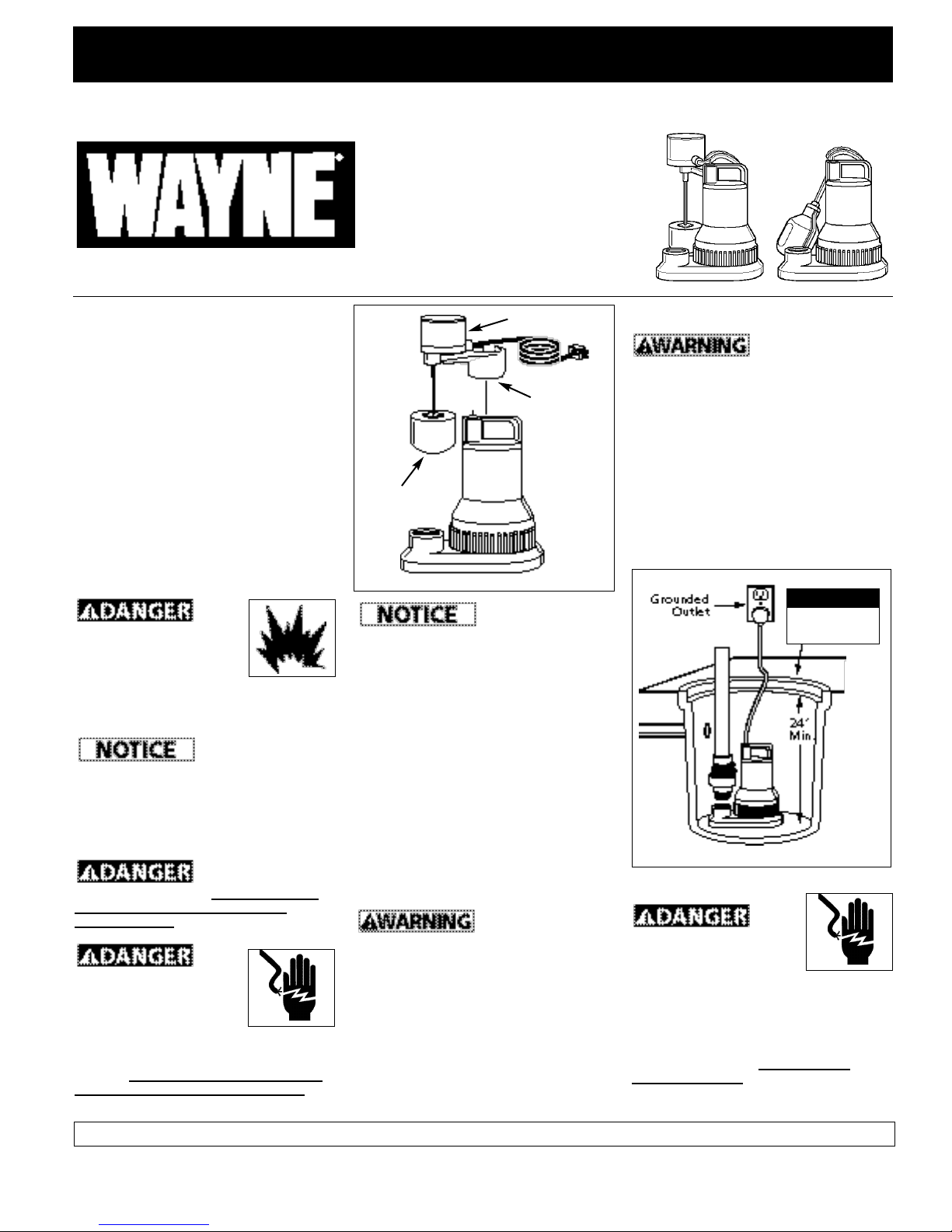
VERTICAL FLOAT SWITCH (FLOAT ONLY)
Place the float bracket onto the handle of
the motor housing and slide the switch
assembly securely into place.
Installation
1. Install pump in a sump pit with minimum
size as shown in Figure 2. Construct
sump pit of tile, concrete, steel or plastic.
2. The unit should be located and rest on a
solid, level foundation. Do not place
pump directly on clay, earth, gravel or
sandy surface. These surfaces contain
small stones, gravel, sand, etc. that may
clog or damage the pump and cause
pump failure.
Flood risk. If
flexible discharge
hose is used, make sure pump is
secured in sump pit to prevent
movement. Failure to secure pump
could allow pump movement and
switch interference and prevent pump
from starting or stopping.
3. Thread check valve (Wayne offers Model
66005-WYN) into pump body carefully
to avoid stripping or cross threading. Do
not use pipe joint sealant.
4. Connect 1-1/2” rigid pipe to rubber boot
on check valve. Reverse boot for 1-1/4”
diameter pipe. Tighten hose clamps.
Support pump and
piping when
assembling and after installation.
Failure to do so could cause piping to
break, pump to fail, etc. which could
result in property damage and/or
personal injury.
5. Protect electrical cord from sharp object,
hot surfaces, oil and chemicals. Avoid
kinking the cord and replace damaged
cords immediately.
IMPORTANT: Make sure there is adequate
room for the switch to operate.
6. A sump pit cover must be installed to
prevent debris from clogging or
damaging the pump.
Operation
Always disconnect the
power source before
attempting to install,
service, relocate or maintain the pump.
Never touch sump pump, pump motor,
water or discharge piping when pump is
connected to electrical power. Never
handle a pump or pump motor with wet
hands or when standing on wet or damp
surface or in water. Fatal electrical
shock could occur.
1. A ground fault circuit interrupter (GFCI)
is required.
Figure 2
Float 11”
Tether 14”
Min. Diameter
Switch Housing
Float
Float
Bracket
Figure 1
Submersible
Sump Pump
© 2005 Wayne Water Systems
For parts, product & service information
visit www.waynepumps.com
REMINDER: Keep your dated proof of purchase for warranty purposes! Attach it to this manual or file it for safekeeping.
4. Fill sump with water. The pump will start
automatically when the water has filled
the sump to the cut-in level. The pump
will stop when the water reaches the
cut-out level. See specifications for cutin/out levels. The pump will recycle
thereafter as required.
5. Do not operate the pump unless it is
submerged in water. Dry running causes
pump failure.
6. The motor is equipped with an
automatic reset thermal protector.
7. While the pump is draining the pit, verify
that the discharge piping is carrying the
water to a point several feet away from
the foundation.
8. If pump discharge line is exposed to
freezing temperature, the exposed line
must be pitched to drain. Trapped water
will freeze and damage the pump.
Maintenance
Always disconnect the
electrical supply before
attempting to install,
service, relocate or
perform any maintenance. If the power
source is out of sight, lock and tag in
the open (off) position to prevent
unexpected power application. Failure
to do so could result in fatal electrical
Operation (Continued)
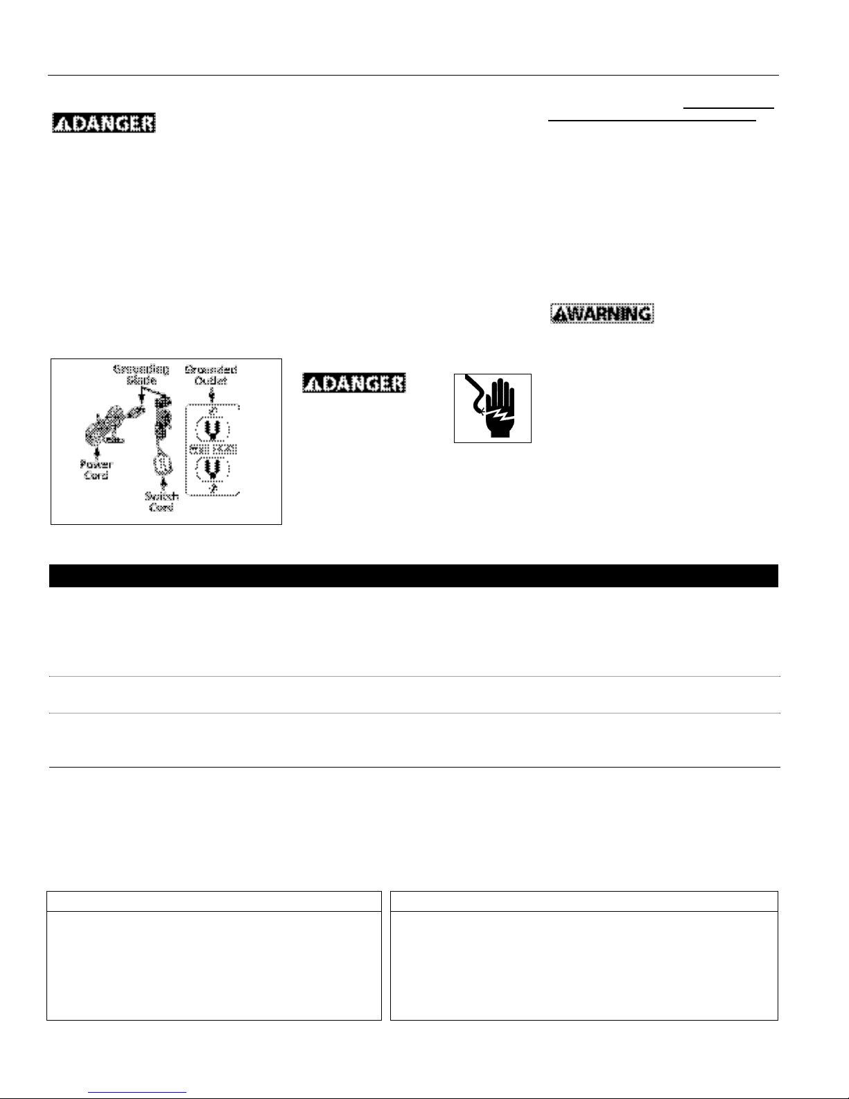
Risk of electrical
shock! This pump
is supplied with a grounding conductor
and grounding type attachment plug.
Use a grounded receptacle to reduce
the risk of fatal electrical shock.
Never cut off the round grounding prong.
Cutting the cord or plug will void the
warranty and make the pump inoperable.
2. This pump is only for use on 120 Volt
(single-phase), 60 hz, 15 amp service and
is equipped with a 3-conductor cord and
3-prong, grounding type plug. Insert the
float switch cord plug directly into a 120
volt outlet.
3. Insert the pump power cord plug directly
into the back of the float switch cord
plug (See Fig. 3).
2
Operating Instructions and Parts Manual
Troubleshooting Chart
Symptom Possible Cause(s) Corrective Action
Pump will not start or
run
Pump starts and stops
too often
Pump will not shut off
or thermal protector
turns off
Pump operates but
delivers little or no
water
1. Blown fuse
2. Low line voltage
3. Defective motor
4. Defective float switch
5. Impeller bound-up
6. Float obstructed
1. Backflow of water from piping
2. Faulty float switch
1. Defective float switch
2. Obstacle in piping
3. Float obstructed
1. Low line voltage
2. Plugged impeller
1. If blown, replace with proper sized fuse or reset breaker
2. If voltage is under 108 volts, check wiring size
3. Replace pump
4. Replace float switch
5. If impeller will not turn, remove housing and remove blockage
6. Make sure float move freely up and down
1. Install or replace check valve (Wayne check valve kit #66005-WYN)
2. Replace float switch
1. Replace float switch
2. Remove pump and clean pump and piping
3. Make sure float move freely up and down
1. If voltage is under 108 volts, check wiring size
2. Clean out impeller
shock. Only qualified electricians
should repair this unit. Improper repair
could result in fatal electrical shock.
1. Let the pump cool for a minimum of two
hours before servicing because the
pump contains hot oil under pressure
and the motor is hot.
2. Disassembly of the motor prior to
expiration of warranty will void the
warranty. If repairs are required, see
troubleshooting chart.
4. Inlet should be kept clean and free of all
foreign objects and inspect annually. A
clogged inlet will damage pump.
5. Pump should be checked monthly for
proper operation.
This pump contains
dielectric oil for
cooling. This oil can be harmful to the
environment. Check the state
environmental laws before disposing
this oil.
Specifications
Power supply requirements.............120V, 60 hz
Motor................................................Single phase, oil filled
Liquid temperature range...............40°F to 120°F
Circuit requirements ........................15 amps (min)
Dimensions .......................................11” high x 9” base
Cut-in level (factory set) ..................Tether...14” Float .....7”
Cut-out level (factory set)................Tether...7” Float .....2 1/2”
Construction
Motor housing .................................Glass reinforced thermoplastic
Volute ...............................................Thermoplastic
Impeller.............................................Glass reinforced thermoplastic
Shaft..................................................416 Stainless steel
Seals ..................................................Buna N
Discharge ..........................................11/2” NPT
Figure 3
www.waynepumps.com
3
Operating Instructions and Parts Manual
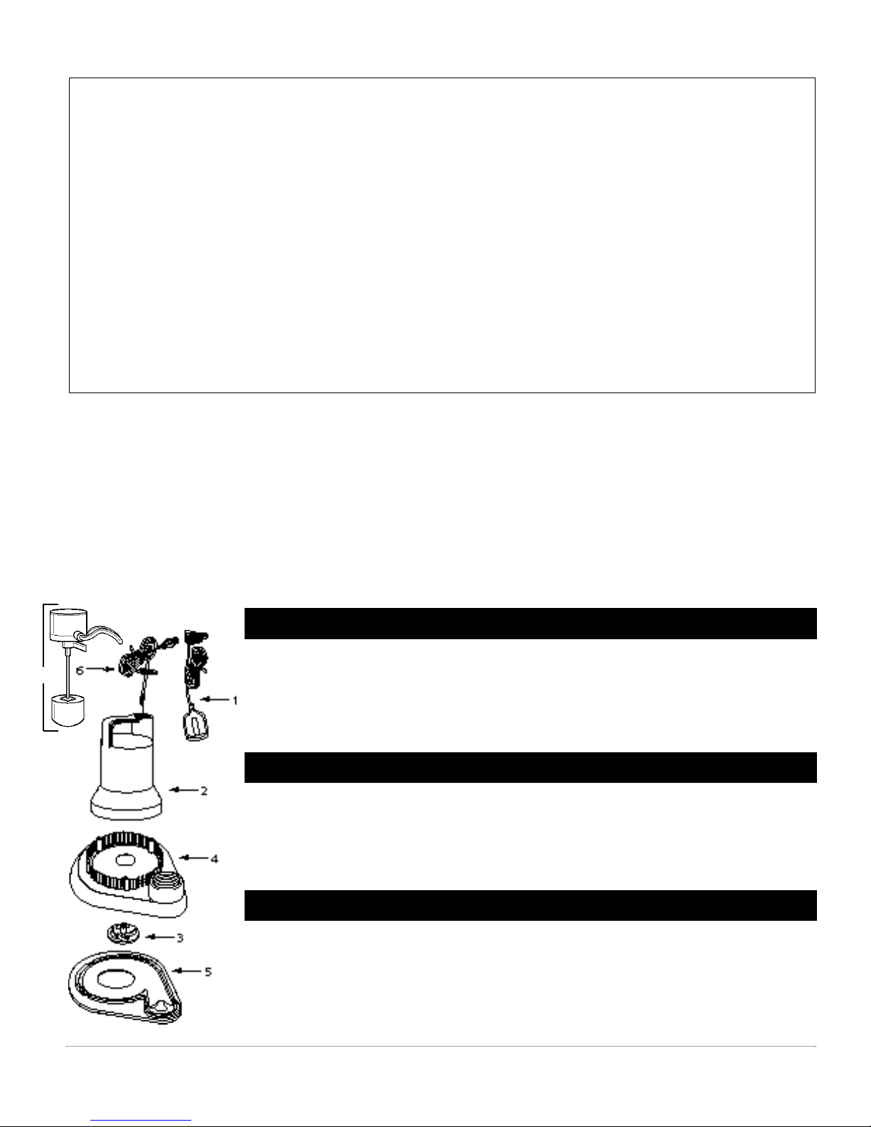
1 Tether Float Switch Kit (WST) 60022-001 60022-001 60022-001 60022-001 60022-001 —
2 Motor Assy Kit 60046-001 60047-001 60048-001 60049-001 60049-002 60049-002
3 Impeller Kit 66010-001 66011-001 66012-001 66013-001 66013-002 66013-001
4 Volute 28416-001 28416-001 28416-001 28416-001 28416-001 28416-001
5 Base 28418-001 28418-001 28418-001 28418-001 28418-001 28418-001
6 Power Cord Kit 62003-001 62003-001 62003-001 62003-001 62003-001 62003-001
7 Vertical Float Switch Kit (WSF) 60051-001 60051-001 60051-001 60051-001 — 60051-001
Ref. Part Numbers for Models WSF50
No. Description W25T/F WST/F30 W33T/F WST/F40 W50T WSF510
For Replacement Parts, call 1-800-237-0987
Pour Les Pièces de Rechange, appeler 1-800-237-0987
Para ordenar repuestos, comuníquese con el distribuidor más
cercano a su domicilio.
Please provide following information:
- Model number
- Serial number (if any)
- Part descriptions and number as shown
in parts list
Address parts correspondence to:
Correspondance:
Puede escribirnos a:
Wayne Water Systems
100 Production Drive
Harrison, OH 45030 U.S.A.
Sírvase darnos la siguiente información:
- Número del modelo
- Número de serie (de haberlo)
- Descripción y número del repuesto según la lista
S’il vous plaît fournir l’information suivante:
- Numéro du Modèle
- Numéro de Série (si présent)
- Description et numéro de la pièce
Replacement Parts List
Liste de Pièces de Rechange
Lista de repuestos
• Only use factory parts to repair this
pump.
• Utiliser seulement les pièces de l’usine
pour la réparation de cette pompe.
• Use sólo repuestos legítimos para
reparar esta bomba.
Limited Warranty
For 90 days from the date of purchase, Wayne Water Systems Division ("Wayne") will repair or re place, at its option, for the original
purchaser any part or parts of its Sump Pumps or Water Pumps (“Product”) found upon examination by Wayne to be defective in
materials or work man ship. Please call Wayne (800-237-0987) for instructions or see your dealer. Be pre pared to provide the model
number and the serial number when exercising this warranty. All transportation charges on Products or parts submitted for repair or
replacement must be paid by purchaser.
This Limited Warranty does not cover Products which have been damaged as a result of accident, abuse, misuse, neglect, improper
installation, improper maintenance, or failure to operate in accordance with Wayne’s written instructions.
THERE IS NO OTHER EXPRESS WARRANTY. IMPLIED WARRANTIES, IN CLUD ING THOSE OF MER CHANT ABIL I TY AND FITNESS FOR
A PARTICULAR PUR POSE, ARE LIMITED TO 90 DAYS FROM THE DATE OF PURCHASE. THIS IS THE EXCLUSIVE REM E DY AND ANY
LIABILITY FOR ANY AND ALL INDIRECT OR CONSEQUENTIAL DAM AG ES OR EXPENSES WHATSOEVER IS EXCLUDED.
Some states do not allow limitations on how long an implied warranty lasts, or do not allow the exclusions or limitations of incidental or
consequential damages, so the above lim i ta tions might not apply to you. This limited war ran ty gives you specific legal rights, and you
may also have other legal rights which vary from state to state.
In no event, whether as a result of breach of contract warranty, tort (in clud ing negligence) or otherwise, shall Wayne or its suppliers be
liable for any special, consequential, incidental or penal damages including, but not limited to loss of profit or revenues, loss of use of the
products or any associated equipment, damage to associated equip ment, cost of capital, cost of substitute products, facilities, services or
replacement power, downtime costs, or claims of buyer’s cus tom ers for such damages.
You MUST retain your purchase receipt along with this form. In the event you need to exercise a warranty claim, you MUST send a copy of
the purchase receipt along with the material or correspondence. Please call Wayne (800-237-0987) for return authorization and instructions.
DO NOT MAIL THIS FORM TO WAYNE. Use this form only to maintain your records.
MODEL NO._______________ SERIAL NO.__________________________ INSTALLATION DATE_____________
ATTACH YOUR RECEIPT HERE
1 Jeu d’Interrupteur Flotteur (WST)66014-001 60022-001 66014-001 60022-001 66014-001 —
2 Jeu d’assem. de moteur 60046-001 60047-001 60048-001 60049-001 60049-002 60049-002
3 Jeu de turbine 66010-001 66011-001 66012-001 66013-001 66013-002 66013-001
4 Volute 28416-001 28416-001 28416-001 28416-001 28416-001 28416-001
5 Base 28418-001 28418-001 28418-001 28418-001 28418-001 28418-001
6 Jeu de cordon d’alimentation 62003-001 62003-001 62003-001 62003-001 62003-001 62003-001
7 Jeu d’Interrupteur À Flotteur (WSF) 60051-001 60051-001 60051-001 60051-001 — 60051-001
Nº de Numéros de Pièces pour Modèles WSF50
Réf. Description W25T/F WST/F30 W33T/F WST/F40 W50T WSF510
1 Flotante/interruptor (WST) 66014-001 60022-001 66014-001 60022-001 66014-001 —
2 Motor 60046-001 60047-001 60048-001 60049-001 60049-002 60049-002
3 Impulsor (propela) 66010-001 66011-001 66012-001 66013-001 66013-002 66013-001
4 Voluta 28416-001 28416-001 28416-001 28416-001 28416-001 28416-001
5 Base 28418-001 28418-001 28418-001 28418-001 28418-001 28418-001
6 Cordón eléctrico 62003-001 62003-001 62003-001 62003-001 62003-001 62003-001
7 Juego de interruptor/ 60051-001 60051-001 60051-001 60051-001 — 60051-001
flotante vertical (WSF)
No. de Número de Piezas para los Modelos WSF50
Ref. Descripción W25T/F WST/F30 W33T/F WST/F40 W50T WSF510
7
www.waynepumps.com
 Loading...