

Page 1
32 Sp
Manual de instrucciones de operación y piezas
Modelos para pozos profundos
Garantía Limitada
Durante tres años a partir de la fecha de compra, Wayne Water Systems ("Wayne") reparará o reemplazará para el
comprador original, según lo que decida, cualquier pieza o piezas de su Juego para estanque, Bombas de resumideros,
Bombas de agua ("Producto") que después de un examen Wayne encuentre que tenían defectos en su material o mano de
obra. Sírvase llamar a la compañía Wayne (800-237-0987, desde EUA) para recibir instrucciones al respecto o comuníquese con
el distribuidor más cercano a su domicilio. Para hacer reclamos bajo esta garantía deberá suministrarnos el número del modelo
y el número de serie del producto. El comprador será responsable de pagar todos los gastos de flete para enviar las piezas o el
Producto para que sean reparados o reemplazados.
Esta Garantía Limitada no cubre los daños que sufra el Producto debido a accidentes, abusos, usos inadecuados, negligencia,
instalación incorrecta, mantenimiento inadecuado o haberse utilizado sin seguir las instrucciones escritas suministradas por la
compañía Wayne.
NO EXISTEN OTRAS GARANTIAS EXPRESAS. LAS GARANTIAS IMPLICITAS INCLUYENDO GARANTIAS EN RELACION AL
MERCADEO O USOS ESPECIFICOS ESTAN LIMITADAS A TRES AÑOS A PARTIR DE LA FECHA DE COMPRA. ESTA ES LA
UNICA GARANTIA DISPONIBLE Y TODAS LAS REPONSABILIDADES CIVILES, DIRECTAS O INDIRECTAS, O GASTOS POR
DAÑOS INDIRECTOS O CONSECUENTES QUEDAN EXCLUIDOS.
Algunos estados no permiten que se establezcan límites en la duración de las garantías implicitas o no permiten que se
excluyan ni se establezcan límites en los daños por incidentes o consecuencias, por lo tanto los límites antes mencionados
podrían ser no válidos. Esta Garantía Limitada le otorga derechos legales especificos, y usted también puede tener otros
derechos que varian de un Estado a otro.
En ningún caso, bien sea por ruptura del contrato de la garantía, responsabilidad civil (incluyendo negligencia) u otra causa,
Wayne o sus distribuidores serán responsables pon daños especiales, consecuentes ni circunstanciales ni penales, incluyendo,
pero no limitados a la pérdida de ganancias, pérdida de uso del producto o equipos asociados, daños a equipos asociados,
costos de capitales, costos para substituir productos, costos para substituir o reemplazar servicios, costos por pérdida de
productividad, o reclamos de clientes del comprador por dichos daños.
DEBE conservar el recibo de compra con esta garantía. En caso de que necesite hacer un reclamo bajo esta garantía, DEBERA
enviarnos una copia del recibo junto con el material o correspondencia. Sírvase comunicarse con la compañía Wayne (800-2370987, en EUA) para recibir autorización e instrucciones para enviar el producto.
NO ENVIE ESTA GARANTIA A WAYNE. Use este documento sólo para mantener sus records.
NO. DEL MODELO _____________________ NO. DE SERIE ________________________ FECHA DE INSTALACION __________________
ANEXE SU RECIBO AQUI
Jet Pump Water Systems
Please read and save these instructions. Read carefully before attempting to assemble, install, operate or maintain the product described.
Protect yourself and others by observing all safety information. Failure to comply with instructions could result in personal injury and/or property damage! Retain instructions for future reference.
© 2008 Wayne Water Systems
Description
Shallow well jet pumps are single stage
domestic water pumps designed for
pumping portable water in applications
where the water is located less than 25
feet vertically from the pump. A
pressure switch is a standard feature.
The shallow well pump can be
mounted to either a precharged,
conventional type or free standing
pressure tank.
Unpacking
After unpacking the jet pump, carefully
inspect for any damage that may have
occurred during transit. Check for
loose, missing or damaged parts.
Safety Guidelines
This manual contains information that
is very important to know and
understand. This information is
provided for SAFETY and to PREVENT
EQUIPMENT PROBLEMS. To help
recognize this information, observe the
following symbols.
Danger indicates
an imminently
hazardous situation which, if not
avoided, will result in death or serious
injury.
Warning indicates
a potentially
hazardous situation which, if not
avoided, could result in death or
serious injury.
Caution indicates a
potentially
hazardous situation which, if not
avoided, may result in minor or
moderate injury.
Notice indicates
important
information, that if not followed, may
cause damage to equipment.
Operating Instructions and Parts Manual Shallow Well Models
General Safety
Information
1. Read the instruction manual included
with the product carefully. Be
thoroughly familiar with the controls
and the proper use of the equipment.
2. Know the pump application,
limitations and potential hazards.
Always install a
pressure relief valve
to match the system pressure rating and
the maximum flow rate.
Do not use to pump
flammable or
explosive fluids such as gasoline, fuel oil,
kerosene, etc. Do not use in explosive
atmospheres. Pump should only be used
with liquids compatible with pump
component materials. Failure to follow
this warning can result in personal injury
and/or property damage.
Disconnect power
and release all
pressure from the system before
attempting to install, service, relocate or
perform any maintenance. Lock the
power disconnect in the open position.
Tag the power disconnect to prevent
unexpected application of power.
Install a screen
around the inlet
pipe to prevent entrapment of swimmers.
3. Drain all liquids from the system
before servicing.
4. Secure the discharge line before
starting the pump. An unsecured
discharge line will whip and possibly
cause personal injury and/or property
damage.
5. Check hoses for weak or worn
condition before each use. Make
certain all connections are secure.
6. Periodically inspect pump and system
components. Perform routine
maintenance as required (See
Maintenance).
7. Personal Safety:
a. Wear safety glasses at all times
when working with pumps.
b. Keep work area clean, uncluttered
and properly lighted - replace all
340106-001 7/08
unused tools and equipment.
c. Keep visitors at a safe distance
from work area.
d. Make the workshop childproof use
padlocks, master switches and
remove starter keys.
8. Do not pump chemicals or corrosive
liquids. Pumping these liquids
shortens the life of the pumps seals
and moving parts and will void the
warranty.
9. When installing pump, cover the
well to prevent foreign matter
from falling into well and
contaminating the water and
damaging internal mechanical
pumping components.
10. Always test the water from the
well for purity before use. Check
with local health department for
test procedure.
11. Complete pump and piping system
MUST be protected against below
freezing temperature. Freezing
temperatures could cause severe
damage and void the warranty.
12. Do not run the pump dry or
damage will occur and will void
warranty.
Risk of electrical
shock. This pump is
designed for indoor installation only.
All wiring should be
performed by a
licensed or certified electrician.
13. For maximum safety, the unit
should be connected to a grounded
circuit equipped with a ground
fault interrupter device.
14. Before installing the pump, have
the electrical outlet checked by a
licensed or certified electrician to
make sure the outlet is properly
grounded.
15. Make sure the line voltage and
frequency of electrical current
supply agrees with the motor
wiring.
REMINDER: Keep your dated proof of purchase for warranty purposes! Attach it to this manual or file it for safekeeping.
For parts, product & service information
visit www.waynewatersystems.com
!
DANGER
!
WARNING
!
CAUTION
NOTICE
!
WARNING
!
WARNING
!
WARNING
!
WARNING
!
WARNING
!
WARNING
Page 2
Para Piezas de Repuestos, Llame al 1-800-237-0987
Puede escribirnos a:
Wayne Water Systems
101 Production Drive
Harrison, OH 45030 U.S.A.
31 Sp
Manual de instrucciones de operación y piezas
Modelos para pozos profundos
1 Motor 32059-001 34142-001 34142-001 1
2 Tornillo 16636-002 16636-002 16636-002 4
3 Placa de sellado 4372-001 4372-001 4372-001 1
4 • Empaquetadura cuadrada de caucho para anillo 17150-001 17150-001 17150-001 1
5 • Ensamblaje de sello del eje 56393 56393 56393 1
6 Impulsor 23285-021 23285-022 23285-022 1
7 Difusor 17148-021 17148-021 17148-021 1
8 Tornillo 67007-001 67007-001 67007-001 2
9 • Anillo en o 15557 15557 15557 1
10 Venturi 17151-002 17151-003 17151-004 1
11 Boquilla 15672 15672 15672 1
12 19,1 mm (3/4”) Tapón de cebado 15921 15921 15921 1
13 Voluta 56869-001 56869-001 56869-001 1
14 6,4 mm (1/4”) NPT Tapón de cebado 16314-002 16314-002 16314-002 1
15 3,2 mm (1/8”) NPT Tapón de cebado 15766-002 15766-002 15766-002 1
17 Base 23029-021 23029-021 23029-021 1
19 Presostato 30010-021 30010-021 30010-021 1
• Juego para reparaciones (Incluyes #4, 5 y 9) 56874-001 56874-001 56874-001 1
No. de Para Los Modelos
Ref. Descripción SWS50-1/2 HP SWS75-3/4 HP SWS100-1 HP Ctd.
17
1
2
3
4
5
6
7
8
11
12
10
13
14
16
9
15
Sírvase proporcionar la suguiente información:
- Número de modelo
- Número de serie (si tiene)
- Descripción y número de repuesto como se muestra
en la lista de repuestos
General Safety
Information (Continued)
16. Do not attempt repairs to the electric
motor. All repairs to the motor must
be completed at a licensed or certified
electrical motor repair shop.
Do not touch an
operating motor.
Modern motors are designed to operate at
high temperatures.
17. Avoid kinking electrical cord and
protect from sharp objects, hot
surfaces, oil and chemicals. Replace
or repair damaged or worn cords
immediately.
Disconnect power
and release all
pressure from the system before
attempting to install, service, relocate or
perform any maintenance. Lock the
power disconnect in the open position.
Tag the power disconnect to prevent
unexpected application of power.
18. Keep fingers and foreign objects
away from ventilation and other
openings. Do not insert any objects
into the motor.
Risk of electric
shock! Never
connect the green (or green and yellow
wire) to a live terminal!
19. To reduce the risk of electrical
shock, the pump should be plugged
directly into a properly installed and
grounded 3-prong grounding type
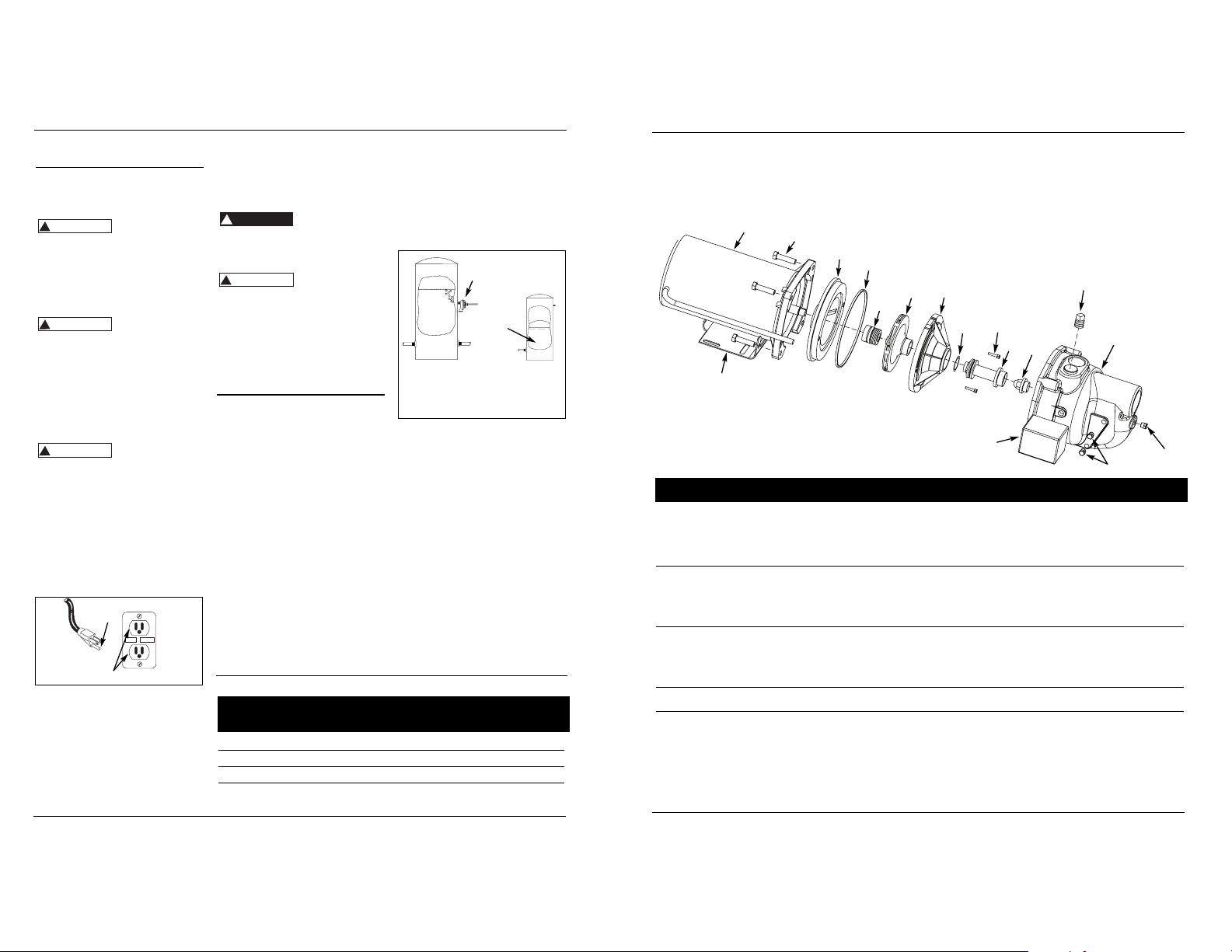
receptacle, as shown in Figure 1.
The green (or green and yellow)
conductor in the cord is the
grounding wire. The motor must be
securely and adequately grounded
for protection against shock.
20. Where a 2-prong is encountered,
replace the plug with a properly
grounded 3-prong receptacle in
accordance with the National
Electrical Code, local codes and
ordinances. To ensure a proper
ground, the grounding means must
be tested by a licensed or certified
electrician.
21. Use only 3-wire extension cords that
have a 3-prong, grounding type
plug, and 3-pole receptacles that
accept the equipment plug.
22. Use wire of adequate size to
minimize voltage drop at the motor.
Do not handle
pump or pump
motor with wet hands, when standing
on a wet or damp surface or when
standing in water. Fatal electrical
shock could occur.
Pump motor is
equipped with an
automatic resetting thermal protector and
may restart unexpectedly. Protector
tripping is an indication of motor
overloading because of operating pump
at low heads (low discharge restriction),
excessively high or low voltage,
inadequate wiring, incorrect motor
connections or defective motor or pump.
Pre-Installation
WATER SUPPLIES
The water supplies illustrated in Figure
12 are possible sources for water.
These water supplies can be divided
into two categories:
SURFACE WATER
Water from a lake, stream, pond and
cistern. This water is usually not fit for
human consumption, but may be
suitable for washing, irrigation or other
household uses.
GROUND WATER
Water found in the water bearing
stratum at various levels beneath the
earth. Of all the fresh water found on
earth only 3 percent is found on the
surface and 97 percent is underground.
TANKS - CONVENTIONAL STORAGE
The function of the tank is to store a
quantity of water under pressure.
When full, the tank contains
approximately 2/3 water and 1/3
2
Operating Instructions and Parts Manual
compressed air. The compressed air
forces the water out of the tank when
a faucet is opened. An air volume
control automatically replaces air lost
or absorbed into the water. The usable
water, or drawdown capacity, of the
tank is approximately 1/6 of the tanks
total volume when operated on a “2040” pressure setting (Figure 2).
TANKS - PRECHARGED STORAGE
A precharged storage tank has a
flexible bladder or diaphragm that acts
as a barrier between the compressed
air and water. This barrier prevents the
air from being absorbed into the water
and allows the water to be acted on by
compressed air at initially higher than
atmospheric pressures (precharged).
More usable water is provided than
with a conventional type tank.
Precharged tanks are specified in terms
of a conventional tank. For example, a
20 gallon precharged tank will have
the same usable water or drawdown
capacity as a 40 gallon conventional
tank, but the tank is smaller in size
(Figure 2).
PRESSURE SWITCH
The pressure switch provides for
automatic operation. The pump starts
when pressure drops to a cut-in setting.
Shallow Well Jet Pump
Air Volume
Control
Type Required
Well X Precharged No
PCA Precharged No
12P & 30P Horizontal Conventional Yes
FX Horizontal Precharged No
CHART 1 - JET PUMP/TANK ASSEMBLIES
Air Volume
Control
Bladder
Conventional
Tank
Precharged
Tank
Figure 2 - Conventional & Precharged
Storage Tanks
Grounded
Pin
Grounded Outlet
Figure 1
www.waynewatersystems.com
!
WARNING
!
WARNING
!
WARNING
RESET
TEST
!
DANGER
!
WARNING
Page 3
30 Sp
Manual de instrucciones de operación y piezas
Modelos para pozos profundos
La bomba no funciona
El motor suena pero no funciona
Desconexión por sobrecarga
La bomba funciona pero no agua
o provee muy poca cantidad
La bomba se prende y apaga continuamente
1. No hay energía eléctrica
2. El fusible se ha quemado o el interruptor se ha
desconectado
3. Interruptor de presión fallado
4. El tubo del interruptor a presión esta obstruído
5. Desconectado por sobrecarga del motor
1. Bajo voltaje en la línea
2. El cableado es demasíado pequeño
3. Los daños o la falta de alineamiento dan lugar
que las piezas rotatorías se peguen
1. Voltaje incorrecto en la línea
2. Los daños o la falta de alineamiento dan lugar
que las piezas rotatorias se peguen
3. Alta temperatura en los alredodores
4. Ciclos rápidos
1. El nivel de agua está por debajo de la toma de la
bomba
2. La válvula de control está demasiado abierta
(pozos profundos)
3. Al cebar no se purgó la descarga
4. Hay fuga en la tubería en el lado del pozo donde
está la bomba
5. Está obsstruida la malla de la bomba o el colador
de aspiración de entrada
6. Boquilla obstruida (pozos profundos)
7. Se ha roto el diafragma del control del volumen
de aire
8. La válvula de aspiración puede estar obstruida o
atascada en la posición de cerrada
9. La bomba no se ha cebado completamente
10. La válvula de control está completamente cerrada
(pozos profundos)
11. Nivel de agua por debajo de lo requerido para
aspirar
12. Tubería de tamaño menor que el requerido
13. Pozo gaseoso
14. Venturi distorsionado
15. Eyector de chorro inadecuado para la aplicación
16. Bomba de tamaño muy pequeño
17. La bomba forma vacios parclales, suena como si
estuviera bombeando cascajo
1. Tanque inundado (Convencional)
2. La tubería del control del volumen de aire está
doblada u obtruida
3. Control de volumen de aire conectado a la salida
incorrecta de la bomba
4. Precarga de tanqueincorrecta (Tanque precargado)
5. Diafragma o bolsa rota (Tanque precargado)
6. Fuga enla tubería de la casa
7. Válvula de pie o válvula de retención atascada en
posición abierta
8. El motor se desconecta por sobrecarga
9. Interruptor de presión incorrectamente ajustado
1. Encienda la corriente eléctrica o llame a la
compañía de suministro eléctrico
2. Cambie el fusible o vuelva a conectar el
interruptor de circuito
3. Cambie el interruptor
4. Limpie o reemplace la tubería de cobre
5. Deje que se enfríe. La sobrecarga se
recalibrará automáticamente
1. Haga un nuevo cableado. Ver la Table 3*
2. Haga un nuevo cableado. Ver la Table 3*
3. Reemplácelas o llévelas a un taller de
servicio para reparaciones
1. Haga un nuevo cableado. Ver la Table 3*
2. Lleve el motor a un taller de reparaciones o
localice donde se pegan las piezas y haga las
reparaciones
3. Coloque la bomba en una zona sombreada
y bien ventilada
4. Vea la sección sobre bombas que funcionan y
se detienon con demasiada frecuencia
1. Baje más el tubo de succión dentro del pozo
2. Repita el procedimiento para cobar
3. Abra el grifo y vuelva a cebar
4. Repare la tubería según sea necesario
5. Límpieia o reemplácela según sea necesario
6. Jale el eyector de chorro y limpie la
obstrucción
7. Repare o cambie el control del volumen de
aire
8. Límpieia o reemplaceia según sea necesario
9. Continúe cebando, haga una pausa cada 5
minutos para que se enfríe el armazón de la
bomba. Vuelva a llenar la bomba según sea
necesario
10. Ajuste la válvula de control según el procedimlento para cebar los pozos profundos
11. Seleccione el ensamblado de la bomba y/o
del eyector de chor ro que correspondan
12. Reemplace según sea necesario
13. Instale un deflector en la entrada a la bomba
para evitar que los gases entren al sistema
14. Inspecciónelo y reemplácelo
15. Adquiera un eyector de chor ro que encaje
en su sistema cuando esté reemplazando
una bomba de otra marca
16. Aumente el caballaje de la bomba
17. Aumente el diámetro de la tubería de succion o disminuya la fricción en la tubería
1. Cambie el tanque o el control del volumen
de aire
2. Límpiela o reemplácela según sea necesario
3. Mueva a la apertura correcta de la bomba
4. Agregue o quite aire cuanto sea necesario
5. Cambie el tanque
6. Localie y repare la fuga
7. Retire y reemplace
8. Vea la sección sobre desconexiones por
sobrecarga
9. Reajuste o cambie el interruptor
* Todas las conexiones eléctricas las debe hacer un electricista certificado o con licencia
Problema Posible(s) Causa(s) Acción a Tomar
Guía de Diagnóstico de Averías
3
Pre-Installation
(Continued)
The pump stops when pressure reaches
a cut-out setting.
PACKAGE SYSTEMS
There are four jet pump/tank
assemblies sold as packages (Chart 1).
WELLS
A new well should be pumped clear of
sand before installing the pump. Sand
will damage the pumping parts and
seal. The drawdown level of the well
should not exceed the maximum rated
depth for the pump. The capacity of
the pump will be reduced and a loss of
prime may occur.
Installation
LOCATION
Select a location as close to the water
supply as possible. Be sure to comply
with any state or local codes regarding
the placement of the pump. The
equipment must be protected from the
elements. A basement or heated pump
house is a good location. Make sure
the pump has proper ventilation. The
temperature surrounding the pump is
not to exceed 100° F (40°C) or nuisance
tripping of the motor overload may
occur.
PIPING
Piping may be copper, steel, rigid PVC
plastic or flexible polyethylene plastic.
Flexible pipe is not
recommended on
suction pipe (inlet pipe).
The pipe must be clean and free of rust
or scale. Use a pipe joint compound on
the male threads of the metal pipe.
Teflon
®
tape should be used with
plastic threads. All connections must
be air tight to insure normal operation.
Slope all inlet piping upwards towards
the pump to prevent trapping air.
Unions or hose couplings can be
installed near pump to facilitate
removal for servicing or storage. A
rubber hose installed between the
water system and the house piping will
reduce the noise transmitted to the
house.
PIPE SIZES
Long horizontal pipe runs and an
abundance of fittings and couplers
decrease water pressure due to friction
loss. See Chart 2 to determine the
proper pipe size.
SHALLOW WELL INSTALLATION
A shallow well pump can be used when
the pump is located within 25 feet
vertically of the water level. Shallow
well pumps have only one pipe
between the pump and the water
supply (Figure 3).
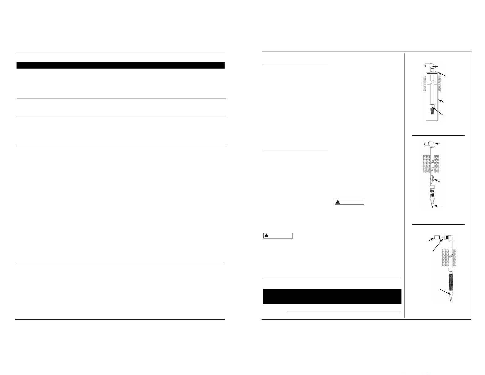
DRILLED WELL (FIGURE 12)
1. Install a foot valve on the first section
of pipe (Figure 3, Illustration A).
2. Lower the pipe into the well.
3. Add pipe until the foot valve is 5
feet below the lowest anticipated
water level.
The foot valve
should be at least
18” from the bottom of the well or
sand or sediment could be drawn into
the system.
4. After proper depth is reached,
install a well seal or pitless adapter
to support pipe and prevent surface
water and other contaminants from
entering well.
5. Slope the horizontal pipe upward
toward the pump to eliminate
trapping air. Sloping the pipe will
also aid in priming the pump.
DRIVEN WELL (FIGURE 12)
1. Drive the point several feet below
the water table.
Operating Instructions and Parts Manual
Shallow Well Jet Pump
CHART 2 - PIPE SIZING
Illustration B
Illustration C
Packer
Type
Foot
Valve
Drive
Point
To Pump
Incline
Check
Valve
Drive
Point
To Pump
Figure 3
To Pump
Illustration A
Well
Seal
Well
Casing
Foot
Valve
Horizontal Distance
Pump Pump (Feet)
Model Opening 0-25 26-100 100-300
Shallow Well Inlet 11/4”1
1
/2”2”
Outlet 3/4” 1” 1
1
/4”
www.waynewatersystems.com
!
CAUTION
!
CAUTION
Page 4
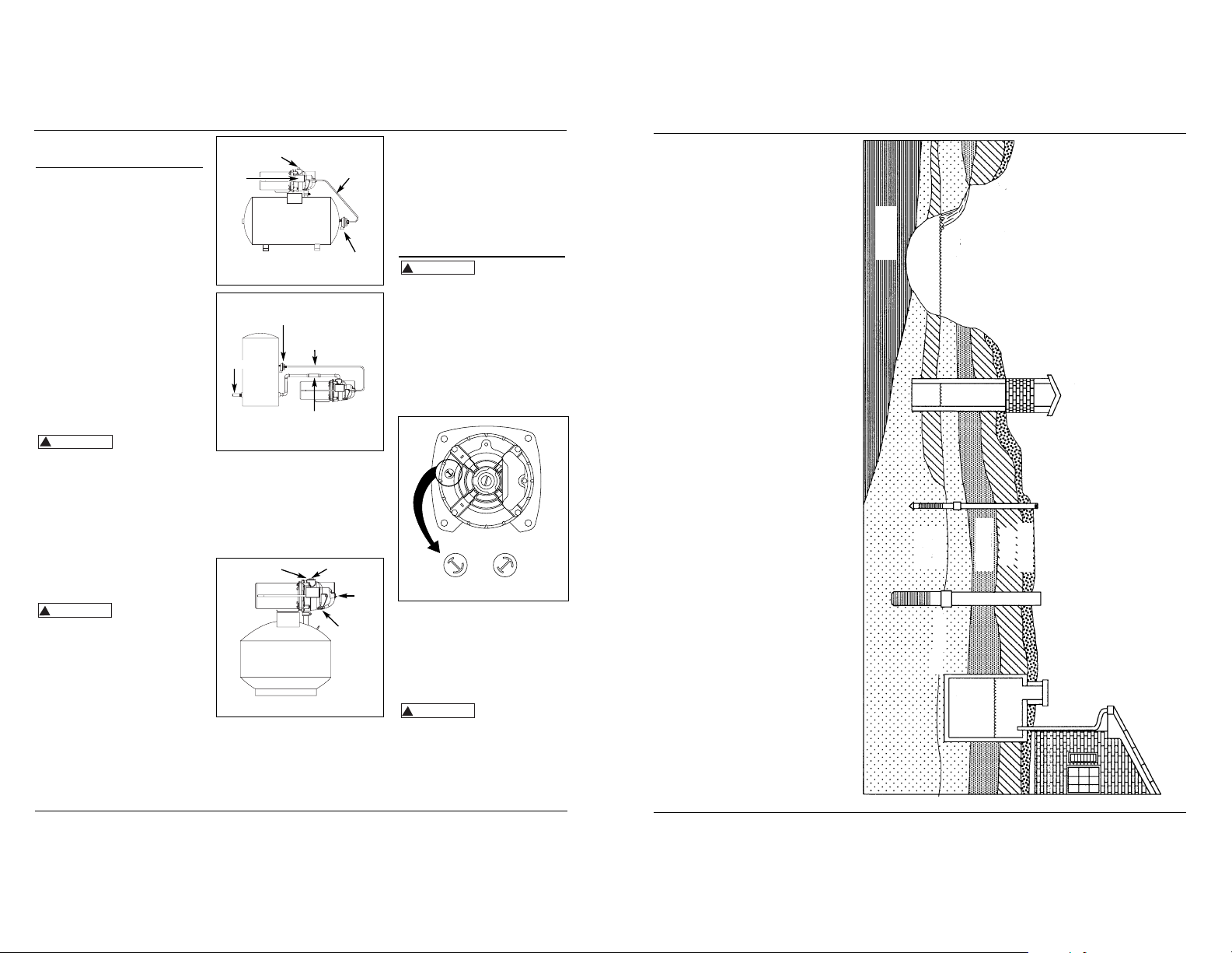
(A) MANANTIAL:
Suministros de Agua
Figura 13 - Suministros de Agua
29 Sp
Manual de instrucciones de operación y piezas
Modelos para pozos profundos
noise transmitted to the house
thrugh the piping.
4. Provide a hose bib (faucet) at the
lowest point in the system to drain
the system for service or storage.
SHALLOW WELL PUMP WITH
PRECHARGED STORAGE TANK
(FIGURE 6)
1. Shut off the power to the pump.
2. Open the faucet nearest the tank
and allow all water to drain from
the tank.
3. Measure the tank precharge at the
valve stem using a tire pressure
gauge.
4
4. If necessary, precharge with an air
pump to 28 - 30 psi on 1/2, 3/4 and 1
HP pumps.
5. Slope the horizontal pipes upward
toward the pump to prevent
trapping air. If the horizontal
distance exceeds 25 feet, see Chart
2 for the recommended pipe size.
Electrical
Risk of electrical
shock. This pump is
designed for indoor installation only.
The voltage of power supply must
match the voltage of the pump. All
above ground well pumps except
SWS50BOOST have dual voltage motors
preset at the factory to 230 volts. The
motors can be converted to 115 volts
by turning the voltage selector to the
desired voltage (See Figure 7). Use a
needle nose pliers to pull the selector
out approximately 1/4”, rotate and
then reinsert in correct position.
Select the proper size wire and fuse
(Chart 3). Time delay fuses are
recommended over standard fuses for
motor circuit protection. All pump
motors have built-in automatic
overload protection that will prevent
damage to the motor due to
overheating.
Do not connect to
electric power
supply until unit is permanently
grounded. Connect ground wire to
approved ground then connect terminal
provided.
A metal underground water pipe or
well casing at least 10 feet long makes
the best ground electrode. If plastic
pipe or insulated fittings are used, run
Installation
(Continued)
NOTE: A packer type foot valve can be
installed in the well (Figure 3,
Illustration B). This type of foot valve
allows the well to be filled with water
when priming and makes the inlet pipe
much easier to test for leaks. Follow
the manufacturer’s instructions when
installing the packer type foot valve.
As an alternative, an in-line check valve
can be used with a driven well (Figure
3, Illustration C). The pipe between the
check valve and the water level will
always be under a vacuum.
Leaking joints or couplings will allow
air to leak into the pipe and cause
abnormal pump operation. Make sure
to use pipe joint compound on all male
pipe threads.
DUG WELL, CISTERN, LAKE AND SPRING
INSTALLATION (FIGURE 12)
1. Install a foot valve on inlet pipe and
lower into water.
The foot valve
should be at least
18” from the bottom of the well or
sand or sediment could be drawn into
the system.
NOTE: When a lake is used as a water
supply, make sure the inlet pipe is deep
enough to be submerged at all times.
Slope the horizontal piping upward
toward the pump to prevent trapping
air. The pipe must be removed during
winter months or protected against
freezing.
Protect the pipe from damage from
swimmers and boats.
Install a screen
around the inlet
pipe to prevent the entrapment of
swimmers.
SHALLOW WELL PUMP WITH
CONVENTIONAL STORAGE TANK
(FIGURES 4 & 5)
1. Install air volume control on tank.
2. Connect the copper tube from the
air volume control to the
uppermost 1/8” NPT opening on the
side of pump. Be sure the
connections are tight. Leaking can
cause the pump not to prime.
3. Install a valve and an isolator hose
between the tank and the house
plumbing to aid in pump removal
for servicing and for reducing the
Operating Instructions and Parts Manual
Shallow Well Jet Pump
Figure 4 - Horizontal Tank
Air
Volume
Control
Tubing
Pressure
Switch
Prime
Plug
Air
Volume
Control
Figure 5 - Vertical Tank
Air
Volume
Control
Outlet
Air Volume
Control
Tubing
Hose
Coupling
Figure 6 - Precharged Storage Tank
28-30 psi
3/4 HP & 1 HP
Motor
www.waynewatersystems.com
Outlet
Priming
Plug
Nozzle
Clean
Out
Drain
Fitting
Figure 7 - Voltage Selector
Un manantial que emerge
de la tierra. Ocurre cuando
el agua en materiales
permeables está atrapada
entre materiales
impermeables tales como
roca o arcilla.
!
CAUTION
!
WARNING
!
WARNING
230 V
115 V
115 V
230 V
!
WARNING
(B) LAGO, ARROYO o ESTANQUE:
Agua superficial, que a menos
que sea tratada, por lo general
no es apta para consumo
humano. Puede ser utilizada
para fines tales como lavado
o irrigación.
(C) POZO EXCAVADO:
Se excava un hoyo de
varios pies de diámetro
hasta una profundidad
basante superficial.
Luego se reviste con
ladrillo, piedra o
concreto para evitar
que se derrumbe.
(D) POZO ACCIONADO:
Se acciona una tubería
con una pantalla con
punta en la tierra, por
debajo de la capa
freática. La profundidad
por lo general es menor
a 15,25 m (50 pies).
Los diámetros comunes
fluctúan entre 2,5 cm (1")
y 5,1 cm (2")
(E) POZO PERFORADO:
Un hoyo perforado en
la tierra con maquinaria y
revestido con tuberías.
Las profundidades
fluctúan entre algunos
pies hasta más de 305 m
(1000 pies). Los diámetros
comunes son 5,1 cm (2"),
7,6 cm (3"), 10,2 cm (4") y
15,2 cm (6") para pozos
de agua de uso doméstico.
(F) CISTERNA:
Un tanque subterráneo
construido para recolectar
agua de lluvias de los
techos. El agua no es
apta para consumo
humano.
ESQUISTO
ACUIFERA
ARENA
CAPA FREATICA
ARROYO,
ESTANQUE
(A) MANANTIAL
(B) LAGO,
(C) POZO EXCAVADO
(D) POZO
ACCIONADO
PERMEABLE
SUPERFICIAL
MATERIAL
ARCILLA
TIERRA
(E) POZO
PERFORADO
(F) CISTERNA
Page 5

5. Sasegure el difusor en la placa de
sellado con los dos pernos.
Cerciórese de que los pernos estén
orientados horizontalmente como
se describe en el paso 2.
6. Coloque con cuidado la
empquetadura de la cubierta en
espiral (voluta) sobre el difusor en la
placa de sellado. En todas las
aplicaciones de conversión, el anillo
de sellado también debe estar
colocado sobre el difusor. En todas
las aplicaciones en pozos poco
profundos se debe tener cuidado de
que los anillos en o (juntas tóricas)
estén limpios y colocados
adecuadamente sobre el Venturi. La
limpieza y la colocación correcta
hacen que exista un uen sellado
dentro del difusor cuando se
ensambla.
7. Acople la cubierta en espiral
(voluta) de la bomba al motor con
los cuatro pernos. Asegúrese de que
la empaquetadura de la cubierta en
espiral (voluta) esté bien colocada y
ajuste bien los pernos.
NOTA: El eje debe poder girar
libremente y la cubierta del extremo
del motor debe estar asegurada antes
de hacer funcionar la bomba.
Mantenimiento
(Continuación)
6. Con un destornillador o una llave
graduable, impida que l eje gire y
retire el impulsor con la mano
(roscado estándar de mano
derecha). Cerciórese de guardar la
placa de sellado de hierro forjado
cuando saque el impulsor del eje.
7. Saque la placa de sellado.
8. Planquee la pieza rotatoria de
sellado del eje para que salga del
impulsor (Figura 10).
9. Empuje o palanquee el
asentamiento de cerámica para
separarlo de la placa de sellado
(Figura 10).
10. Elimine las partículas sueltas del
núcleo del impulsor y la placa de
sellado.
INSTALACIÓN DE UN NUEVO SELLO
DEL EJE
Antes de
manipular las piezas del sello del eje
límpiese las manos con un paño. El
polvo y la grasa pueden dañar el sello.
1. Humedezca con aceite de cocina, la
parte interior de la cavidad del sello
en la placa de sellado y los
empaques de caucho acopados que
rodean el nuevo asentamiento de
cerámica. Tenga cuidado de no
raspar la superficie de cerámica del
asentamiento del sello y empuje el
asentamiento incluido en el caucho
en la cavidad del sello en la placa de
sellado. Use una rondana de cartón
para proteger la superficie pulida
cuando empuje contra el
asentamiento de cerámica con
cualquier objeto. Cerciórese de
sacar la rondana de cartón.
28 Sp
2. Deslice con cuidado la placa de
sellado sobre el eje de modo que no
se mueva el sello de su posición en
la placa de sellado. Durante el
ensamblado, la placa de sellado
debe estar orientada de modo que
los dos orificios estén en una línea
horizontal a través del eje del
motor y que las cuatro (4) clavijas
de localización de la parte posterior
estén alineadas con las lengüetas
del armazón del motor (Figura 11).
Esta ubicación se debe hacer para
asegurar un drenaje y cebado
adecuados.
3. Sitúe la pieza rotatoria del sello del
eje en el impulsor y presiónela para
que quede en su sitio. Tenga
cuidado de no presionar contra la
superficie pulida del sello.
4. Coloque el impulsor en el eje y
ajústelo bien (Figura 12).
Manual de instrucciones de operación y piezas
Modelos para pozos profundos
Figura 10 - Remoción del Sello del Eje
y el Asentamiento de
Cerámica
Place de
Sellado
Asentamiento
de Cerámica
Pieza Rotatoria
de Sellado del
Eje
Anillo de
Caucho de
Asentamiento
Impulsor
Figura 11 - Reemplazo de la Placa Sellado
Orificios para
los Tornillos
Eje del
Motor
Placa de Sellado
Asentamiento
del Sello
Figura 12 - Eje del Motor
Motor
Impulsor
Asentamiento
del Sello
Para que el Sellado Sea
Adecuado, es Necesario
que la Cara del Sello este
Limpia
5
Operating Instructions and Parts Manual
Shallow Well Jet Pump
Distance In Feet
From Meter To Motor
Dual 0 51 101 201
Element To To To To
Fuse 50 100 200 300
HP Volt 250V Wire Size
115 15 14 14 12 10
230 10 14 14 14 14
115 15 14 14 10 8
230 10 14 14 14 14
115 20 12 12 10 8
230 10 14 14 14 14
CHART 3 - RECOMMENDED FUSE & WIRING DATA - 60 HZ MOTORS
1/2
3/4
1
www.waynewatersystems.com
Electrical (Continued)
a wire directly to the metal well casing
or use a ground electrode furnished by
the power company.
There is only one proper ground
terminal on the unit. The terminal(s) is
located under the pressure switch
cover, is painted green and is identified
as GRD. The ground connection must
be made at this terminal (Figure 8).
The ground conductor must not be
smaller than the circuit conductors
supplying the motor.
Disconnect power
and release all
pres
sure from the system before
attempting to install, service, relocate or
perform any maintenance.
Operation
PRIMING THE SHALLOW WELL PUMP
To prevent damage
to the pump, do not
start motor until pump has been filled
with water.
1. Remove prime plug (Figure 4 or 5).
2. Fill pump and piping completely full
of water.
3. Replace the prime plug.
4. Open a faucet to vent the system.
5. Start the motor. Water will pump in
a few minutes. If pump fails to
prime in 5 minutes, stop motor and
refill pump with water. Priming
time is proportional to the amount
of air in inlet pipe.
6. Let the system operate for several
minutes to flush all pipes.
7. Close faucet and allow pump to
build pressure in tank. When the
pressure reaches the cut-out setting,
the motor will stop.
The system is now in operation and will
automatically cycle on demand.
Maintenance
Disconnect power
and release all
pressure from the system before
attempting to install, service, relocate or
perform any maintenance. Lock the
power disconnect in the open position.
Tag the power disconnect to prevent
unexpected application of power.
Protect the pump
from freezing
during winter conditions.
DRAINING THE PUMP
Drain openings are provided on all
models. To drain the pump:
1. Remove drain plug and prime plug
to vent the system.
2. Drain all piping to a point below
the freeze line.
DRAINING THE TANK
Conventional tanks can be drained by
opening an outlet at the lowest point
in the system. Remove plug or the air
volume control to vent the tank.
Precharged tanks force virtually all the
water from the tank when system
pressure is released. No draining is
necessary.
RESTARTING PUMP
If the pump has been serviced, drained
or has not been used for some time, be
sure there is water in the pump
housing (volute) and the piping to the
well. There must be water in the pump
housing (volute) at all times when the
pump is running to avoid internal
damage of seal members (Priming the
Shallow Well).
WATERLOGGED TANKS:
CONVENTIONAL
When a tank system has an inadequate
ratio of air and water, the pump will
start and stop often and eradically.
1. Disconnect the power to the pump.
2. Open the lowest faucet in the
system to release all pressurized
water in the system.
3. Prime the pump (Priming the
Shallow Well).
4. Reconnect the power to the pump.
NOTE: As the pump refills the tank with
water, the air volume control supplies
the tank with the correct air to water
ratio for the system to operate. If the air
volume control is good, the pump will
shut off at the desired cut-off and will be
adjusted correctly.
WATERLOGGED TANKS:
PRECHARGED
If a precharged tank becomes
waterlogged, the bladder is normally
leaking or broken.
1. Test the tank by depressing the air
valve. The air valve will expel water if
the bladder is broken.
2. Replace the tank.
NOTE: Once a bladder is leaking or
broken, the bladder cannot be repaired.
The tank must be replaced.
L2
3
L1
1
Figure 8 - Electrical Connections
Motor
Motor
Line
Line
Ground
!
PRECAUCION
L1
L2
3
1
!
WARNING
!
WARNING
!
WARNING
!
CAUTION
Page 6

NOTA: Si la cámara elástica tiene fugas o
se ha roto, no se puede reparar. Hay que
reemplazar el tanque.
LUBRICACIÓN
Los cojinetes que se usan en las bombas
vienen lubricados de fábrica para una
duración permanente y no necesitan
lubricación adicional.
PRECARGADO
En todos los tanques se pierde algo de
aire a través de la cámara elástica. Para
evitar que el tanque falle, examine la
precarga una vez al año.
1. Abra el grifo más cercano al tanque y
deje que drene toda el agua del
tanue.
2. Mida la precarga del tanque en el
pitón de la válvula con un medidor de
presión para llantas.
3. Si es necesario, ajuste con una bomba
de aire la precarga a una presion
entre 1,93 y 2,07 bar en bombas de
1/2, 3/4 y 1 CP.
PARA SACAR EL SELLO USADO
DEL EJE
Gire el
interruptor de desconexión a la posición
“off.”
1. Abra el grifo más cercano al tanque y
deje que drene toda el agua del
tanque.
2. Saque los cuatro pernos que
mantienen la cubierta en espiral de la
bomba (voluta) unida al motor
(Figura 9).
3. Separe la cubierta en espiral de la
bomba (voluta) del motor para
exponer el difusor y la placa de
sellado.
4. Retire los dos pernos y el difusor de
la placa de sellado para exponer el
impulsor.
5. Saque la tapa pequeña del extremo
del motor opuesto al impulsor
Funcionamiento
CEBADO DE LA BOMBA PARA
POZOS POCO PROFUNDOS
Para
evitar
dañar la bomba, no arranque el motor
hasta que la haya llenado con agua.
1. Retire el tapón para cebar (Figura 4
o 5).
2. Llene la bomba y la tubería
completamente con agua.
3. Vuelva a colocar el tapón para
cebar.
4. Abra el grifo para purgar el
sistema.
5. Arranque el motor. El agua
empezará a bombearse en pocos
minutos. Si la bomba no se ceba en
5 minutos, detenga el motor y
vuelva a llenar la bomba con agua.
El tiempo necesario para cebar es
proporcional a la cantidad de agua
en la tubería de ingreso.
6. Deje que el sistema funcione por
varios minutos para que se limpien
todos los tubos.
7. Cierre el grifo y deje que la bomba
desarrolle presión en el tanque.
Cuando la presión alcance el límite
establecido, el motor se detendrá.
El sistema está ahora en
funcionamiento y hará ciclos
automáticos según la demanda.
Mantenimiento
Desco-
necte la
corriente eléctrica y libere toda la presión
del sistema antes de intentar instalar,
darle servicio, mantenimiento o cambiarlo
de lugar. Trabe el desconector de
corriente en la posición de abierto y
rotúlelo para evitar una aplicación
inesperada de corriente.
Proteja
la
bomba para que no se congele durante
los meses de inierno.
DRENAJE DEL BOMBA
Todos los modelos vienen con
aberturas para drenar. Para drenar la
bomba:
1. Saque el tapón de drenaje y el
tapón para cebar a fin de que se
vacíe el sistema.
2. Drene todas las tuberías hasta un
nivel por debajo de la línea de
congelación.
27 Sp
DRENAJE DEL TONQUE
Los tanques convencionales se pueden
drenar al abrir una salida en el punto
más bajo del sistema. Retire el tapón o
el control de volumen del aire para
vaciar el tanque.
Los tanques precargados fuerzan
prácticamente toda el agua del tanque
cuando se libera la presión del sistema.
No es necesario drenar.
PARA VOLVER A HACER
FUNCIONAR LA BOMBA
Si a la bomba se le ha dad servicio, se la
ha drenado o no se la ha usado por
algun tiempo, cerciorese de que haya
agua en la cubierta en espiral (voluta) y
en la tuberia del pozo. En todo
momento debe haber agua en la
cubierta en espiral de la bomba (voluta)
cuando este funcionando para evitar
danos internos en las piezas de sellado
(Vea las secciones sobre cebado de
pozos poco profundos o de pozos
profundos).
MOVIMIENTO DE AGUA SE HACE
LENTO: CONVENCIONAL
Cuando el sistema de un tanque tiene
una relación inadecuada entre aire y
agua, la bomba arrancará y se detendrá
con frecuencia en forma errática.
1. Desconecte la corriente eléctrica
que va a la bomba.
2. Abra el grifo más bajo del sistema
para liberar toda el agua
presurizada del sistema.
3. Cebe la bomba (Ccebado para pozos
poco profundos o pozos profundos).
4. Vuelva a conectar la corriente
eléctrica a la bomba.
NOTA: Conforme la bomba vuelve a
llenar el tanque con agua, el control de
volumen de aire suministra al tanque la
relación adecuada de aire y agua para
que el sistema funcione. Si el control del
volumen de aire está bien, la bomba se
parará en el nivel límite que se haya
establecido y se ajustará
adecuadamente.
MOVIMIENTO DE AGUA SE HACE
LENTO: : PRECARDGADO
Si en un tanque precargdo, el
movimiento de agua se hace lento,
habitualmente se debe a que la cámara
elástica tiene fugas o se ha roto.
1. Pruebe el tanque presionando la
válvula de aire. La válvula de aire
expelerá agua si la cámara elástica se
ha roto.
2. Reemplace el tanque.
Manual de instrucciones de operación y piezas
Modelos para pozos profundos
Tornillos de
Casquetes
Figura 9 - Bomba Convertible
para Pozos
Placa de
Sellado
Difusor
Cubierta en
Espiral (Voluta)
Impulsor
Motor
Maintenance
(Continued)
LUBRICATION
The bearings used in the pumps are
lifetime lubricated at the factory and
require no additional lubrication.
PRECHARGED TANK
Some air is lost through the bladder in
any tank. To prevent tank failure, check
the tank precharge on a yearly basis.
1. Open a faucet nearest the tank and
allow all water to drain from the
tank.
2. Measure the tank precharge at the
valve stem using a tire gauge.
3. If necessary, adjust the precharge
with an air pump 28 - 30 psi on 1/2,
3/4 and 1 HP pumps.
REMOVING OLD SHAFT SEAL
Turn disconnect
switch to “off”
position.
1. Open a faucet nearest the tank and
allow all water to drain from the
tank.
2. Remove the four cap screws holding
the pump housing (volute) to the
motor (Figure 9).
3. Separate the pump housing
(volute) from the motor to expose
the diffuser and the seal plate.
4. Remove the two cap screws and
diffuser from the seal plate to
expose the impeller.
5. Remove the small end cap on the
end of the motor opposite the
impeller.
6. With a large screwdriver or
adjustable wrench, keep the shaft
from rotating and remove the
impeller by hand (standard right
hand thread). Be sure to hold onto
the seal plate when removing the
impeller from the shaft.
7. Remove the seal plate.
8. Pry the rotating shaft seal member
from the impeller (Figure 10).
9. Push or pry the ceramic seat free
from the seal plate (Figure 10).
10. Remove loose particles from
impeller hub and seal plate.
Shallow Well Jet Pump
Operating Instructions and Parts Manual
INSTALLING NEW SHAFT SEAL
Before handling
shaft seal parts
wipe hands clean. Dirt or grease can
damage the seal.
1. Wet the inside of the seal cavity on
seal plate and the rubber cup
enclosing the new ceramic seat with
cooking oil. Be careful not to
scratch the ceramic surface of the
seal seat and push seat enclosed in
rubber into seal cavity on seal plate.
Use a cardboard washer to protect
polished surface when pushing
against ceramic seat with any
object. Be sure to remove
cardboard washer.
2. Carefully slip seal plate over shaft.
Do not disturb seal position in seal
plate. The seal plate must be
orientated during assembly so the
two screw holes are on a horizontal
line across the motor shaft and the (4)
locating pins on the back of the seal
plate line up with the tabs on the
motor housing (Figure 11). This
placement should be done to ensure
proper draining and priming.
3. Place rotating shaft seal member in
position on impeller and press into
place. Take care not to press against
polished seal surface.
4. Position impeller on shaft and tighten
securely (Figure 12).
5. Secure diffuser to seal plate using the
two cap screws. Be sure the screws
are orientated on a horizontal line as
described in Step 2.
6. Carefully position pump housing
(volute) gasket over the diffuser onto
the seal plate. In all shallow well
applications care must be taken that
the o-ring is clean and properly
positioned on the venturi. Cleaning
and positioning makes a good seal
inside the diffuser when assembled.
7. Assemble the pump housing (volute)
to the motor using the four cap
screws. Be sure the pump housing
(volute) gasket is positioned correctly
and tighten the screws securely.
NOTE: Shaft must rotate freely and
motor end cap should be secured
before operation.
Seal
Plate
Seal
Seat
Figure 12 - Motor Shaft
Figure 11 - Seal Plate Replacement
Screw Holes
Motor
Shaft
Motor
Impeller
Seal
Plate
Seal Facing Must
Be Clean For
Proper Seal
Figure 10 - Removing Shaft Seal &
Ceramic Seat
Seal
Plate
Ceramic
Seat
Rotating
Shaft Seal
Member
Rubber
Seat Ring
Impeller
Cap
Screws
Figure 9 - Shaft Seal
Seal
Plate
Diffuser
Pump
Housing
(Volute)
Impeller
Motor
www.waynewatersystems.com
6
!
CAUTION
!
CAUTION
!
ADVERTENCIA
!
ADVERTENCIA
!
PRECAUCION
!
PRECAUCION
Page 7

26 Sp
Instalación
(Continuación)
3. Instale una válvula y una manguera
de aislamiento entre el tanque y la
tubería de la casa para facilitar
poder separar la bomba cuando se
le dé servicio, y disminuir el ruido
transmitido a la casa a través de la
tubería.
4. Coloque una manguera de desagüe
con llave en el punto más bajo del
sistema para poder drenar cuando
se vaya a dar servicio o guardar el
equipo.
BOMBA PARA POZOS POCO
PROFUNDOS CONTANQUE DE
ALMACENAMIENTO PRECARGADO
(FIGURE 6)
1. Desconecte la corriente eléctrica
que va a la bomba.
2. Abra el grifo más cercano y deje que
drene toda el agua del tanque.
3. Mida la precarga del tanque en el
pitón de la válvula con un medidor
de presión para llantas.
4. Si es necesario, precargue con una
bomba de aire a una presión entre
1,93-2,07 bar en las bombas de 1/2,
3/4 y 1 CP.
5. Incline los tubes horizontales hacia
arriba en dirección de la bomba para
evitar que quede aire atrapado. Si la
distancia horizontal excede los 7,62 m
(25 pies), use tubos de los tamaños
que se recomiendan en la Tabla 2.
Eléctricas
Existe
riesgo de
un choque eléctrico.
Esta bomba está
diseñada únicamente para ser instalada en
interiores.
El voltaje de la fuente de suministro
eléctrico debe ser similar al de la bomba.
Todas las bombas para pozo de
instalación sobre superficie, excepto la
SWS50BOOST, tienen motores de doble
voltaje preconfigurados en la fábrica a
230 voltios. Para conectarlas a circuitos de
115 voltios simplemente gire la perilla al
voltaje deseado (Vea la Figura 6). Use
una pinza (alicate) de punta afilada para
halar la perilla aproximadamente un 6,4
mm (1/4”), gírela y colóquela en su
posición correcta.
Seleccione los alambres y el fusible del
tamaño adecuado (Tabla 3). Para la
protección del circuito del motor, se
recomiendan los fusibles que
interrumpen por un tiempo en vez de
los fusibles convencionales. Todos los
motores de bomba tienen incorporada
una protección automática contra
sobrecargas que evitará que se dañe el
motor debido a sobrecalentamiento.
No haga la
conexión
a
la fuente de suministro eléctrico hasta
que la unidad esté conectada a tierra en
forma permanente. Conecte el alambre a
tierra a una conexión a tierra aprobada y
luego conecte el terminal que se
suministra.
Una tubería subterránea para agua y una
armazón de pozo de por lo menos 3 m
(10 pies) largo sons los mejores electrodos
de tierra. Si se usa tubería de plástico o
adaptadores con aislamiento, pase un
alambre directamente a la armazón
metálica del pozo o use un electrodo de
tierra proporcionado por la compañíia de
servicio eléctrico.
La unidad sólo tiene un terminal
adecuado para conexión a tierra que
está localizado debajo de la cubierta
del interruptor a presión, está pintado
de verde y se identifica como GRD. La
conexión a tierra se debe hacer desde
este terminal (Figura 8). El conductor a
tierra no debe ser más pequeño que los
conductores de circuito que vienen con
el motor.
Desconecte
el
suministro eléctrico y libere toda la
presión del sistema antes de intentar
instalar, dar servicio, reubicar o llevar a
cabo cualquier mantenimiento.
Distancia en Metros
de Medidor a Motor
Fusible 0 15,6 30,8 61,3
de Dos To To To To
Elementos 15,2 30,5 61 91,4
CP Voltios 250V Tamano del alambre
115 15 14 14 12 10
230 10 14 14 14 14
115 15 14 14 10 8
230 10 14 14 14 14
115 20 12 12 10 8
230 10 14 14 14 14
TABLA 3 - DATOS DE LOS FUSIBLES Y ALAMBRES RECOMMENDADOS-MOTORES DE 60 HZ
1/2
3/4
1
Manual de instrucciones de operación y piezas
Modelos para pozos profundos
Figura 6 - Tanque de Almacenamiento
Precargado
1,93-2,07 bar
3/4 CP & 1 CP
L2
3
L1
1
Figura 8 - Conexiónes Eléctricas
Motor
Motor
Motor
Conexión
Conexion a Tierra
Conexión
Salida
Tapón del
Sistema de
Cebado
Tronçon
de Buse
Adaptador
de drenaje
Figura 7 - Perilla para Seleccionar el
Voltaje
7
Shallow Well Jet Pump
Operating Instructions and Parts Manual
(A) SPRING:
Water Supplies
Figure 13 - Water Supplies
www.waynewatersystems.com
A spring that emerges
from the ground.
Occurs when water in
permeable materials is
trapped between
impermeable
material as rock or clay.
!
ADVERTENCIA
230 V
115 V
230 V
115 V
!
ADVERTENCIA
L2
3
!
ADVERTENCIA
L1
1
for purposes such as washing
or irrigation.
depth. It is then lined
with brick, stone or
concrete to prevent
cave-in.
the water table.
The depth is usually
less than 50 feet.
Available
diameters are
1" through 2".
range from a few feet
to over 1000 feet.
Common well diameters
are 2", 3", 4" and 6" for
domestic water wells.
The water is not fit
for human consumption.
SHALE
(B) LAKE, STREAM or POND:
Surface water, unless treated,
is usually not safe for human
consumption. It may be used
(C) DUG WELL:
A hole is excavated
several feet in diameter
to a fairly shallow
(D) DRIVEN WELL:
Pipe with a pointed
screen is driven into
the ground below
(E) DRILLED WELL:
A hole bored into the
earth with machinery and
lined with pipe. Depths
(F) CISTERN:
An underground tank
built to collect rain
water from rooftops.
(A) SPRING
(B) LAKE,
STREAM, POND
(C) DUG WELL
(D) DRIVEN WELL
WATER
MATERIAL
CLAY
TOP SOIL
BEARING
SAND
PERMEABLE
(E) DRILLED WELL
WATER TABLE
(F) CISTERN
Page 8

La válvula
de aspiración debe estar por lo menos a 45 cm
(18 pulg.) del fondo del pozo de no ser
así, podría aspirar arena o sedimento
dentro del sistema.
4. Después que se haya alcanzado la
profundidad adecuada, instale un
sellado del pozo o un adaptador
para sostener la tubería y evitar que
el agua de la superficie y otros
contaminantes entren al pozo.
5. Incline el tubo horizontal hacia
arriba en direccion a la bomba para
evitar que quede aire atrapado. La
inclinacion del tubo tambien ayuda
a cebar la bomba.
POZO ACCIONADO (FIGURA 12)
1. Lleve la punta a varios pies por
debajo del nivel del agua
subterránea.
NOTA: Se puede instalar en el pozo
una válvula de aspiración de tipo
tampón (Figura 3, Ilustracion B). Este de
tipo de válvula de aspiración permite
que el pozo se llene con agua cuando
se está cebando y permite verificar con
mayor facilidad si hay escapes en la
tubería de ingreso. Cuando instale la
válvula de aspiración de tipo tampón
siga las instrucciones del fabricante.
Como alternativa, se puede usar una
válvula unidireccional en la tubería de
un pozo excavado (Figura 3, Ilustración
C). La tubería entre la válvula
unidireccional y el nivel de agua estará
siempre bajo un vacío.
Las uniones o conexiones con fugas
dejan que entre aire en la tubería y dan
lugar a que la bomba no funcione bien.
Asegúrese de usar un compuesto para
uniones de tubería en todos los
roscados machos de los tubos.
INSTALACIÓN DEL POZO EXCAVADO,
CISTERNA, LAGO Y MANANTIAL
(FIGURA 12)
1. Instale una válvula de aspiración en
la tubería de entrada y bájela
dentro del agua.
La válvula
de
aspiración debe estar a por lo menos 45
cm (18”) del fondo del pozo de no ser
así se podría aspirar arena o sedimento
dentro del sistema.
NOTA: Cuando se usa un lago como
fuente de suministro de agua,
asegúrese que la tubería de entrada
25 Sp
tenga la suficiente profundidad para
que esté siempre sumergida. Proteja
la tubería para que no la dañenni los
bañistas ni los botes.
Incline la tubería horizontal hacia
arriba en dirección de la bomba para
evitar que quede aire atrapado. Se
debe sacar la tubería durante los
meses de invierno o protegerla para
que no se congele.
Proteja la tubería para que no la
dañenni los bañistas ni los botes.
Instale
una
malla alrededor de la tubería de entrada
para evitar que qu eden atrapados los
bañistas.
BOMBA PARA POZOS POCO
PROFUNDOS CON TANQUE DE
ALMACENAMIENTO
CONVENCIONAL (FIGURAS 4 Y 5)
1. Instale el control del volumen de
aire en el tanque.
2. Conecte el tube de cobre del
control del volumen de aire en la
abertura NPT de 3,2 mm (1/8”)
superior al lado de la bomba.
Cerciórese de que las conexiones
estén bien ajustadas. Las fugas
puede evitar que la bomba se
cebe.
Instalación
(Continuación)
No se
recomienda tubería flexible para el
tubo de succión (tubo de entrada).
Los tubos deben estar limpios y no
estar oxidados ni con descamaciones.
Utilice un compuesto para conexiones
de tubería en el roscado macho de los
tubos de metal. Para los roscados de
plástico se debe usar una cinta de
Teflon
®
. Todas las conexiones deben
estar herméticas para asegurar un
funcionamiento normal.
Incline todas las tuberías de entrada
hacia arriba en dirección a la bomba
para evitar que quede aire atrapado.
Se pueden instalar uniones o
conectores de manguera cerca de la
bomba para que sea fácil sacarlas
cuando se necesite dar servicio o
almacenarlas. Una manguera de
caucho instalada entre el sistema de
agua y la tubería de la casa reducirá el
ruido que se transmite a la casa.
TAMANOS DE LOS TUBOS
Los tendidos largos de la tubería
horizontal y el uso de numerosos
adaptadores y conectores disminuyen
la presión de agua debido a la pérdida
por fricción. Vea la tabla 2 para
determinar el tamaño adecuado de
tubo.
INSTALACIÓN EN POZOS POCO
PROFUNDOS
Se puede usar una bomba para pozos
poco profundos cuando esta ubicada
dentro de los 25 pies en sentido vertical
del nivel de agua. Las bombas para
pozos poco profundos tienen un solo
tubo entre la bomba y la fuente de
suministro de agua.
POZO PERFORADO (FIGURA 12)
1. Instale una válvula de aspiración en
la primera sección del tubo (Figura
3, Ilustración A).
2. Baje el tubo dentro del pozo.
3. Aumente la tubería hasta que la
válvula de aspiración este a 1,5 m (5
pies) por debajo del nivel de agua
más bajo que se anticipa.
Manual de instrucciones de operación y piezas
Modelos para pozos profundos
Figura 4 - Tanque Horizontal
Tampón
Tuberia
del
Control
del
Volumen
de Aire
Control
del
Volumen
de Aire
Presostato
Figura 5 - Tanque Vertical
Salida
Tubería del Control
del Volumen de Aire
Conector de
la Manguera
Control del Volumen de Aire
Operating Instructions and Parts Manual
Shallow Well Jet Pump
8
Symptom Possible Cause(s) Corrective Action
Troubleshooting Chart
Pump will not run
Motor hums but will not run
Overload trips
Pump runs but delivers little or
no water
Pump starts and stops too
often
1. Power off
2. Blown fuse or tripped breaker
3. Faulty pressure switch
4. Pressure switch tubing obstructed
5. Motor overload tripped
1. Low line voltage
2. Wiring too small
3. Damage or misalignment causing rotating
parts to bind
1. Incorrect line voltage
2. Damage or misalignment causing rotating
parts to bind
3. High surrounding temperature
4. Rapid cycling
1. Water level below pump intake
2. Control valve open too far (deep well)
3. Discharge not vented while priming
4. Leaking in piping on well side of pump
5. Well screen or inlet strainer clogged
6. Clogged nozzle (deep well)
7. Air volume control diaphragm ruptured
8. Foot valve may be clogged or stuck closed
9. Pump not fully primed
10. Control valve completely closed (deep well)
11. Water level below maximum lift
specification
12. Undersized piping
13. Gaseous well
14. Distorted venturi
15. Incorrect jet for application
16. Undersized pump
17. Pump cavitates, sounds like pumping gravel
1. Water logged tank (conventional tank)
2. Air volume control tubing kinked or clogged
3. Air volume control tubing connected to
wrong opening on pump
4. Incorrect tank precharged (precharged tank)
5. Ruptured diaphragm/bladder (precharged
tank)
6. Leak in house piping
7. Foot valve or check valve stuck open
8. Motor overload tripping
9. Improperly adjusted pressure switch
1. Turn power on or call power company
2. Replace fuse or reset circuit breaker
3. Replace switch
4. Clean or replace copper tubing
5. Let cool. Overload will automatically
reset
1. Rewire. See Chart 3*
2. Rewire. See Chart 3*
3. Replace or take to service shop for
repair
1. Rewire. See Chart 3*
2. Take to motor repair shop or locate
and repair mechanical binding
3. Provide a shaded, well-ventilated area
for pump
4. Pump starts and stops too often section
1. Lower suction pipe further into well
2. Repeat priming procedure
3. Open faucet, repeat priming procedure
4. Repair piping as needed
5. Clean or replace as necessary
6. Pull jet and clear obstruction
7. Repair or replace air volume control
8. Clean or replace as needed
9. Continue priming, pausing every 5
minutes to cool pump body. Refill
pump as needed
10. Adjust control valve per deep well
priming procedure
11. Select applicable pump and/or jet
assembly
12. Replace as needed
13. Install baffle on pump intake to prevent gas from entering system
14. Inspect and replace
15. Purchase a jet matched to your system
when replacing another brand pump
16. Increase horsepower of pump
17. Increase suction plumbing diameter or
decrease pipe friction
1. Replace tank or air volume control
2. Clean or replace as needed
3. Move to correct pump opening
4. Add or release air as needed
5. Replace tank
6. Locate and repair leak
7. Remove and replace
8. See overload trips section
9. Readjust or replace switch
* All rewiring and motor repair must be done by licensed or certified professionals
www.waynewatersystems.com
!
PRECAUCION
!
PRECAUCION
!
PRECAUCION
!
ADVERTENCIA
Page 9

Pre-Instalación
(Continuación)
vaciado es aproximadamente 1/6 del
volumen total del tanque cuando se
hace funcionar a una presion de “1,38 2,76 bar” (Figure 2).
TANQUES - ALMACENAMIENTO
PRECARGADO
Un tanque de almacenamiento
precargado tiene una cámara elástica o
un diafragma flexible que funciona
como una barrera entre el aire
comprimido y el agua. Esta barrera
evita que el aire sea absorbido por el
agua y permite que el agua reciba el
efecto del aire comprimido a una
presión inicialmente más alta que la
presión atmosféria (precargado). Este
tipo de tanque proporciona más agua
que los tanques convencionales. Por
ejemplo, un tanque precargado de 75,7
L (20 galones) rendirá la misma
cantidad de agua utilizable o
capacidad de vaciado que un tanque
convencional de 151,4 L (40 galones),
con la ventaja de que el tanques es más
pequeño. (Figura 2).
PRESOSTATO
El interruptor que funciona con la
presión permite la operación
automática. La bomba comienza a
24 Sp
funcionar cuando la presión baja al
nivel límite establecido para funcionar
y dejará de hacerlo cuando la presión
llegue al nivel límite establecido para
apagarse.
PAQUETES DE SISTEMAS
Hay cuatro ensamblados de bomba y
tanque que se venden como paquettes
(Tabla 1).
POZOS
Un pozo nuevo debe bombearse para
que quede sin arena antes de instalar la
bomba. La arena dañará las piezas y los
sellos de la bomba. El nivel más bajo
del pozo no debe exceder la
profundidad máxima permitida para la
bomba. Esto haría que se reduzca la
capacidad de la bomba y se podría
perder el cebado.
Instalación
UBICACIÓN
Escoja una ubicación lo más cercana
posible a la fuente de suministro de
agua.
Asegúrese de cumplir con los códigos
estatales o locales sobre ubicación de
bombas. El equipo debe protegerse de
la intemperie. Una buena ubicación es
un sótano o una casita de bombeo
calentada. Cerciórese de que la bomba
tenga una ventilación adecuada. La
temperatura alrededor de la bomba no
debe exceder de 40° C (100° ) ya que
podrían ourrir desconexiones molestas
del motor por estar sobrecargado.
TUBERÍA
La tubería puede ser de cobre, acero,
PVC plástico rigido o polietileno
plástico flexible.
Distancia Horizontal
Modelo de Abertura de (Metres)
Bomba la Bomba 0-7,62 7,93-30,5 7,93-91,4
TABLA 2 - TAMAÑO DE LOS TUBOS
Ilastración B
Ilastración C
Valvula de Pie
Tipo Portadora
Punta de Acción
A la Bomba
Válvula de
Retención en
Línea
Punta de
Acción
A la Bombo
Figura 3
A la Bomba
Ilastración A
Obturador
del Pozo
Tubería de
Revestimiento
del Pozo
Válvula de Pie
Manual de instrucciones de operación y piezas
Modelos para pozos profundos
Control de Volumen
de Aire
Cámara
Elástica
Tanques
Convencional
Tanques
Precargado
Figura 2 - Tanque de Almacenamiento
Convencional y Precargado
Inlet 3,18 cm 3,81 cm 5,08 cm
Outlet 19,1 mm 2,54 cm 3,18 cm
Pozo
Profundo
9
Shallow Well Jet Pump
Operating Instructions and Parts Manual
For Replacement Parts, call 1-800-237-0987
Please provide following information:
- Model number
- Serial number (if any)
- Part description and number as shown in parts list
Address parts correspondence to:
Wayne Water Systems
101 Production Drive
Harrison, OH 45030 U.S.A.
1 Motor 32059-001 34142-001 34142-001 1
2 Screw 16636-002 16636-002 16636-002 4
3 Seal plate 4372-001 4372-001 4372-001 1
4 • Square ring rubber gasket 17150-001 17150-001 17150-001 1
5 • Shaft seal assembly 56393 56393 56393 1
6 Impeller 23285-021 23285-022 23285-022 1
7 Diffuser 17148-021 17148-021 17148-021 1
8 Screw 67007-001 67007-001 67007-001 2
9 • O-ring 15557 15557 15557 1
10 Venturi 17151-002 17151-003 17151-004 1
11 Nozzle 15672 15672 15672 1
12 Pipe plug 3/4” 15921 15921 15921 1
13 Volute 56869-001 56869-001 56869-001 1
14 Pipe plug 1/4” NPT 16314-002 16314-002 16314-002 1
15 Pipe plug 1/8” NPT 15766-002 15766-002 15766-002 1
16 Base 23029-021 23029-021 23029-021 1
17 Pressure switch 30010-021 30010-021 30010-021 1
• Repair kit (Includes #4, 5 and 9) 56874-001 56874-001 56874-001 1
Ref. Part Numbers for Models
No. Description SWS50-1/2 HP SWS75-3/4 HP SWS100-1 HP Qty.
17
1
2
3
4
5
6
7
8
11
12
10
13
14
16
9
15
www.waynewatersystems.com
Page 10

19. Para reducir el riesgo de choque
eléctrico, la bomba se debe
enchufar directamente en un
tomacorriente para tres patillas
debidamente instalado y conectado
a tierra, como se muestra en la
Figura 1. El conductor verde (o
verde y amarillo) del cordón es el
alambre a tierra. Para la protección
contra el choque eléctrico, el motor
debe estar conectado a tierra en
forma segura y adecuada.
20. Cuando se encuentre un
tomacorriente para dos patillas se
debe reemplazar con uno para tres
patillas de acuerdo con el Código
Nacional de Electricidad de EUA y
los códigos y ordenanzas locales.
Para estar seguro de que la
conexión a tierra sea adecuada, la
debe probar un electricista
certificado o con licenia.
21. Use solamente cordones de
extensión de tres alambres que
tengan un enchurfe de tres puntas y
tomacorriente un que acepte el
enchufe del equipo.
22. Use alambres del tamaño adecuado
para reducir al mínimo la caída de
voltaje en el motor.
No mani-
pule la
bomba ni su motor con las manos
mojadas, ni cuando esté parado en
superficies húmedas, mojadas o en el
agua. Puede ocurrir un choque eléctrico
fatal.
23 Sp
Manual de instrucciones de operación y piezas
Informaciones
Generales de Seguridad
(Continuación)
Existe
riesgo de
un choque eléctrico. Está bomba está
diseñada únicamente para ser instalada en
interiores.
Todas las
conexiones eléctricas las debe hacer un
electricista certificado o con licenia.
13. Para máxima seguridad, la unidad
se debe conectar a un circuito con
conexión a tierra que tenga un
dispositivo de interrupción para
cuando falle la conexión a tierra.
14. Antes de instalar la bomba, haga
que un electricista certificado o con
licencia verifique el tomacorriente
para comprobar que tenga una
conexión a tierra adecuada.
15. Asegúrese de que las conexiones
eléctricas del motor sean adecuadas
para el voltaje y la frecuencia de la
linea de suministro eléctrico.
16. No intente reparar el motor
eléctrico. Todas las reparaciones del
motor deben hacerse en un taller
certificado o con licenia para
reparar motores eléctricos.
No toque
un motor
en funcionamiento. Los motores
modernos están diseñados para trabajar a
altas temperaturas.
17. Evite doblar el cordón de
electricidad y protéjalo de objetos
cortantes, superficies calientes,
aceite y químicos. Reemplace o
repare los cordones dañados o
gastados de inmediato.
Descon-
ecte la
corriente eléctrica y libere toda la presión
del sistema antes de intentar instalar,
darle servicio, mantenimiento o cambiarlo
de lugar. Trabe el desconector de corriente
en la posicion de abierto, y rotúlelo para
evitar una aplicación inesperada de
corriente.
18. Mantenga los dedos y los objetos
extraños alejados de la ventilación y
otras aberturas. No inserte ningún
objeto en el motor.
Existe
riesgo de
un choque eléctrico! Nunca conecte el
alambre verde (o el verde y amarillo) a un
terminal con corriente.
El motor
de la
bomba está equipado con un protector
automático termal de recalibración por lo
que puede volver a funcionar en forma
inesperada. Cuando el protector hace la
desconexión, esto es una indicación de
que el motor está sobrecargado porque la
bomba esta funcionando a niveles bajos
(restricción de descarga baja), el voltaje es
excesivamente bajo o alto, el cableado es
inadecuado, las conexiones del motor no
son las correctas o el motor o la bomba
tiene defectos.
Pre-Instalación
FUENTES DE SUMINISTRO DE AGUA
Las posibles fuentes de suministro de
agua se ilustran en la Figurra 16. Se
pueden clasificar en dos categorías:
AGUAS DE SUPERFICIE
Agua de un lago, arroyo, laguna o
cisterna. Esta agua habitualmente no
es adecuada para consumo humano,
pero podría usarse para lavar, irrigar u
otros usos domésticos.
AGUAS SUBTERRÁNEAS
El agua que se encuentra en los
diversos estratos por debajo de la
superficie. De toda el agua dulce que
se encuentra en la tierra, solamente el
3% está en la superficie y el 97% es
subterrénea.
TANQUES - ALMACENAMIENTO
CONVENCIONAL
El objeto de un tanque es almacenar
una cantidad de agua bajo presion.
Cuando esta lleno, el tanque contiene
aproximadamente 2/3 de agua y 1/3 de
aire comprimido. El aire comprimido
fuerza el agua a salir del tanque
cuando se abre un grifo. Un control del
volumen de aire reemplaza
automaticamente el aire perdido o
absorbido por el agua. La cantidad de
agua utilizable o la capacidad de
!
Modelos para pozos profundos
Se Necesita
Control del
Tipo Volume de Aire
Pozo X Precargado No
PCA Precargado No
12P & 30P Horizontal Convencional Sí
FX Horizontal Precargado No
TABLA 1 - ENSAMBLADOS DE
Terminal de
Conexión a
Tierra
Tomacorrientes
Conectado a Tierra
Figure 1
Operating Instructions and Parts Manual
Shallow Well Jet Pump
10
Limited Warranty
For three years from the date of purchase, Wayne Water Systems (“Wayne”) will repair or replace, at its option, for the
original purchaser any part or parts of its Pond Kit, Sump Pumps or Water Pumps (“Product”) found upon examination by
Wayne to be defective in materials or workmanship. Please call Wayne (800-237-0987) for instructions or see your dealer. Be
prepared to provide the model and serial number when exercising this warranty. All transportation charges on Products or
parts submitted for repair or replacement must be paid by purchaser.
This Limited Warranty does not cover Products which have been damaged as a result of accident, abuse, misuse, neglect,
improper installation, improper maintenance, or failure to operate in accordance with Wayne’s written instructions.
THERE IS NO OTHER EXPRESS WARRANTY. IMPLIED WARRANTIES, INCLUDING THOSE OF MERCHANTABILITY AND
FITNESS FOR A PARTICULAR PURPOSE, ARE LIMITED TO THREE YEARS FROM THE DATE OF PURCHASE. THIS IS THE
EXCLUSIVE REMEDY AND ANY LIABILITY FOR ANY AND ALL INDIRECT OR CONSEQUENTIAL DAMAGES OR EXPENSES WHATSOEVER IS EXCLUDED.
Some states do not allow limitations on how long an implied warranty lasts, or do not allow the exclusions or limitations of
incidental or consequential damages, so the above limitations might not apply to you. This limited warranty gives you
specific legal rights, and you may also have other legal rights which vary from state to state.
In no event, whether as a result of breach of contract warranty, tort (including negligence) or otherwise, shall Wayne or its
suppliers be liable for any special, consequential, incidental or penal damages including, but not limited to loss of profit or
revenues, loss of use of the products or any associated equipment, damage to associated equipment, cost of capital, cost of
substitute products, facilities, services or replacement power, downtime costs, or claims of buyer’s customers for such
damages.
You MUST retain your purchase receipt along with this form. In the event you need to exercise a warranty claim, you MUST
send a copy of the purchase receipt along with the material or correspondence. Please call Wayne (800-237-0987) for return
authorization and instructions.
DO NOT MAIL THIS FORM TO WAYNE. Use this form only to maintain your records.
MODEL NO. _____________________ SERIAL NO. ________________________ INSTALLATION DATE _____________________
ATTACH YOUR RECEIPT HERE
www.waynewatersystems.com
ADVERTENCIA
!
ADVERTENCIA
!
ADVERTENCIA
!
ADVERTENCIA
!
ADVERTENCIA
!
ADVERTENCIA
!
PELIGRO
RESET
TEST
Page 11

Sistemas de Agua
Con Bomba de Chorro
© 2008 Wayne Water Systems
Descripción
Las bombas de chorro para pozos poco
profundos son bombas de agua de una
sola etapa para uso doméstico y
diseñadas para bomear agua potable en
aplicaciones, en las culas, el agua está a
menos de 6,62 m (25 pies( de la bomba
en sentido vertical. Las bombas para
pozos profundos incluyen un
interruptor que funciona con la presión
como característica estándar. Las
bombas para pozos poco prfundos se
pueden montar en tanques
precargados, convencionales o
independientes a presión.
Para Desempacar
Al desempacar este producto, reviselo
con cuidado para cerciorarse de que
este en perfecto estado. Igualmente,
cerciorese de apretar todos los pernos,
tuercas y conexiones antes de usarlo.
Medidas de Seguridad
Este manual contiene informacion que
es muy importante que sepa y
comprenda. Esta informacion se la
suministramos como medida de
SEGURIDAD y para EVITAR PROBLEMAS
CON EL EQUIPO.
Esto le
indica
que hay una situación inmediata que le
ocasionaria la muerto o heridas de
gravedad.
Esto le
indica
que hay una situación que podría
ocasionarle la muerte o heridas de
gravedad.
Esto le
indica
que hay una situación que podría
ocasionarle heridas no muy graves.
Esto le
indica
una información importante, que de no
seguirla, le podría ocasionar daños al
equipo.
Manual de instrucciones de operación y piezas Modelos para pozos profundos
Informaciones
Generales de
Seguridad
1. Lea con atención el manual de
instrucciones incluido con este
producto. Familiarícese bien con los
controles y el uso adecuado del
equipo.
2. Conozca las aplicaciones, las
limitaciones y los posibles peligros de
la bomba.
Instale
siempre
una válvula de alivio de la presión para
que la presión del sistema y el flujo
máximo correspondan con los que debe
tener el sistema.
No use la
bomba
para líquidos inflamables ni explosivos
como gasolina, aceite, querosén, etc. No la
use en ambientes explosivos. La bomba
sólo se debe usar con líquidos que sean
compatibles con los materiales de que
están hechas las piezas de la bomba. El no
cumplir con estas advertencias puede
provovar lesiones personales y/o daños
materiales.
Descon-
ecte la
corriente eléctrica y libere toda la presión
del sistema antes de intentar instalar,
darle servicio, mantenimiento o cambiarlo
de lugar. Trabe el desconector de
corriente en la posicion de abierto, y
rotúlelo para evitar una aplicación
inesperada de corriente.
Instale
una malla
alrededor de la tubería de entrada para
evitar que queden atrapados los bañistas.
3. Antes de darle servicio, drene todos
los líquidos del sistema.
4. Mantenga sujeta la tubería de
descarga antes de hacer funcionar la
bomba. Una tubería de descarga que
no esté sujeta golpeará y es posible
que cause lesiones personales y/o
daños materiales.
5. Antes de cada uso, inspeccione las
mangueras para cerciorarse de que
no estén débiles ni gastadas.
340106-001 7/08
Asegúrese de que todas las
conexiones estén seguras.
6. Inspeccione periódicamente la
bomba y los componentes del
sistema. Lleve a cabo el
mantenimiento de rutina según sea
necesario (Vea Mantenimiento).
7.
Seguridad personal:
a. Use anteojos de seguridad
todo el tiempo que trabaje con
la bomba.
b. Mantenga la zona de trabajo
despejada, limpia y con la
iluminación adecuada, guarde
todas las herramientas y el
equipo que no se hayan usado.
c. Mantenga a los visitantes a una
distancia segura de la zona de
trabajo.
d. Haga que el taller sea a
“prueba de ninos,” use candados, interruptores maestros y
retire las llaves de arranque.
8. No bombee químicos ni líquidos
corrosivos. El bombear ese tipo de
líquidos acorta la vida de los sellos
de las bombas y las piezas móviles e
invalidará la garantía.
9. Cuando instale la bomba, cubra el
pozo para evitar que caigan dentro
materiales extraños y contaminen
el agua y dañen los componentes
mecánicos internos de la bomba.
10. Antes de usar el agua, haga
siempre controles de pureza.
Pregunte en el departamento de
salud local sobre el procedimiento
para los controles.
11. El sistema completo de la bomba y
la tubería DEBE estar protegido
contra temperaturas por debajo del
punto de congelamiento. Las
temperaturas de congelamiento
pueden causar daños serios e
invaldiar la garantía.
12. No haga funcionar la bomba en seco,
si lo hace, se puede dañar.
Sírvase leer y conservar estas instrucciones. Léalas con cuidado antes de intentar armar, instalar, operar o efectuar mantenimiento al producto
descrito. Protéjase a sí mismo y a los demás observando la información de seguridad. El no cumplir con estas instrucciones podría provocar
lesiones personales y/o daños materiales. Conserve estas instrucciones para futura referencia.
22 Sp
RECORDATORIO: ¡Guarde su comprobante de compra con fecha para fines de la garantía!
Adjúntela a este manual o archívela en lugar seguro.
Systèmes D’Eau
De Pompe À Jet
S’il vous plaît lire et conserver ces instructions. Lire attentivement avant de monter, installer, utiliser ou de procéder à l’entretien du produit
décrit. Se protéger ainsi que les autres en observant toutes les instructions de sécurité, sinon, il y a risque de blessure et/ou dégâts matériels!
Conserver ces instructions comme référence.
© 2008 Wayne Water Systems
Description
Les pompes à jet pour puits de surface
sont des pompes à eau à une étage à
usage domestique conçues pour le
pompage d’eau potable là où la source
d’eau est située moins de 7,62 m
verticalement de la pompe. Un manostat
est standard. La pompe pour puits de
surface peut être montée sur un réservoir
de pression chargé d’avance, traditionnel,
ou autoportant.
Déballage
Lors du déballage de la pompe à jet,
l’inspecter soigneusement afin de
rechercher toute trace de dommage
susceptible de s’être produit en cours de
transport. Vérifier pour des pièces
dégagées, endommagées, ou manquantes.
Directives de
Sécurité
Ce manuel contient de l’information très
importante de connaître et de savoir qui
est fournie pour la SÉCURITÉ et pour
ÉVITER LES PROBLÈMES D’ÉQUIPEMENT.
Rechercher les symboles suivants pour
cette information.
Danger
indique
une situation hasardeuse imminente
qui, si pas évitée, résultera en perte de
vie ou en blessures graves.
Avertisse-
ment
indique une situation hasardeuse
potentielle qui, si pas évitée, résultera
en perte de vie ou en blessures graves.
Attention
indique
une situation hasardeuse potentielle
qui, si pas évitée, pourrait résulter en
blessures.
Avis
indique
de l’information importante pour
éviter le dommage à l’équipement.
Manuel d’Utilisation et Pièces de Rechange Modèles Pour Puits De Surface
Généralités sur la
Sécurité
1. Lire attentivement le manuel
d’instructions compris avec le produit.
Bien se familiariser avec les contrôles
et le fonctionnement correct de
l’équipement.
2. Connaissez l’application de la pompe,
ses limites et tous les risques.
Toujours
installer
une soupape de sûreté correspondante à
la classification de pression du système et
au taux de débit maximum.
Ne pas
pomper
les liquides inflammables ou explosifs tels
que l’essence, l’huile à chauffage, le
kérosène, etc. Ne pas utiliser dans un
atmosphère explosif. Utiliser la pompe
seulement avec les liquides compatibles
avec les matériaux de fabrication de la
pompe. Manque de suivre cet
avertissement peut résulter en blessures
graves et/ou en dégâts matériels.
Mettre
hors
circuit et dissiper toute la pression du
système avant d’essayer de monter, de
déplacer ou de procéder au service ou à
l’entretien. Verouiller le sectionneur de
puissance dans la position ouverte.
Étiquetter le sectionneur de puissance
afin d’éviter l’alimentation inattendue.
Installer
un écran
de protection autour du tuyau
d’admission pour empêcher
d’emprisonner les nageurs.
3. Purger tous les liquides du système
avant de procéder au service.
4. Fixer la ligne de décharge avant le
démarrage de la pompe. Une ligne
qui n’est pas bien fixée pourrait
fouetter et causer des blessures
personnelles et/ou le dégât matériel.
5. Inspecter les tuyaux pour la faiblaisse
ou l’usure avant chaque usage.
S’assurer que tous raccordements
soient sûrs.
6. Inspecter la pompe et les pièces
détachées du système
périodiquement. Procéder à
340106-001 7/08
l’entretien ordinaire au besoin (Voir
la section Entretien).
7.
Sécurité Personnelle:
a. Toujours porter des lunettes de
sécurité pendant l’utilisation
d’une pompe.
b. Garder l’endroit de travail pro
pre, pas encombré et bien
éclairé. Ranger tous les outils
et l’équipement dont on ne se
sert pas.
c. Garder les visiteurs à distance
respectueuse de l’endroit de
travail.
d. Protéger l’atelier des enfants
en utilisant des cadenas et des
interrupteurs principals.
Enlever les clés de démarrage.
8. Ne pas pomper de produits
chimiques ni de liquides corrosives.
Le pompage de ces liquides peut
raccourcir la durée des joints et des
pièces mobiles de la pompe et
niera la garantie.
9. Couvrir le puits pendant
l’installation de la pompe afin
d’empêcher le débris de tomber
dans le puits qui pourrait
contaminer l’eau et endommager
les pièces mécaniques internes de
pompage.
10. Toujours faire l’essai de l’eau du
puits pour la pureté avant l’usage.
Contacter votre Ministère de Santé
pour la méthode de mise à l’essai.
11. Le système complet de pompe et
de tuyaux DOIT être protégé contre
les températures inférieures à zéro.
Les témpératures congélantes
peuvent causer le dommage
sérieux et nieront la garantie.
12. Ne pas faire fonctionner la pompe
au sec, ceci l’endommagera.
Risque
de
secousse électrique. Cette pompe est
conçue pour l’installation à l’intérieure
seulement.
Toute
nstallation de fils doit être effectuée par un
électricien certifié ou diplômé.
11 Fr
MÉMENTO: Gardez votre preuve datée d'achat à fin de la garantie!
Joignez-la à ce manuel ou classez-la dans un dossier pour plus de sécurité.
!
PELIGRO
!
ADVERTENCIA
!
PRECAUCION
AVISO
!
ADVERTENCIA
!
ADVERTENCIA
!
ADVERTENCIA
!
ADVERTENCIA
!
DANGER
!
AVERTISSEMENT
!
ATTENTION
AVIS
!
AVERTISSEMENT
!
AVERTISSEMENT
!
AVERTISSEMENT
!
AVERTISSEMENT
!
AVERTISSEMENT
!
AVERTISSEMENT
Page 12

21 Fr
Manuel d’Utilisation et Pièces de Rechange
Pompe À Jet Pour Puits De Surface
Garantie Limitée
Pendant trois ans à compter de la date d’achat, Wayne Water Systems ("Wayne") va réparer ou remplacer, à sa discrétion,
pour l’acheteur original toute pièce ou pièces du Kit D’Étang, de ces Pompes De Puisard ou Pompes À Eau ("Produit")
déterminées défectueuses, par Wayne, soit pour les matériaux ou la fabrication. Veuillez appeler Wayne (800-237-0987) pour
des instructions ou contacter votre marchand. S’assurer d’avoir, à sa disposition, le numéro du modèle afin d’effectuer cette
garantie. Les frais de transport des Produits ou pièces soumis pour leur réparation ou leur remplacement sont la responsabilité
de l’acheteur.
Cette Garantie Limitée ne couvre pas les Produits qui se sont fait endommagés suite à un accident, une utilisation abusive, un
mauvais usage, de la négligence, une mauvaise installation, un mauvais entretien, ou une utilisation non conforme aux
instructions écrites de Wayne
IL N’EXISTE AUCUNE AUTRE GARANTIE OU DÉCLARATION. LES GARANTIES EXPRESSES, Y COMPRIS CELLES DE
COMMERCIALISABILITÉ ET D’ADAPTATION À UNE FONCTION PARTICULIÈRE, SONT LIMITÉES À TROIS ANS À COMPTER DE
LA DATE D’ACHAT. CECI EST LE SEUL RECOURS EXCLUSIF ET TOUTE AUTRE RESPONSABILITÉ POUR TOUT AUTRE DOMMAGE
QUELCONQUE INDIRECT OU DÉPENSES QUELCONQUES SONT EXCLUS.
Certaines Provinces n’autorisent pas de limites de durée pour les garanties implicites, ni l’exclusion ni la limite des dommages
fortuits ou indirects. Les limites précédentes peuvent donc ne pas s’appliquer. Cette garantie limitée donne à l’acheteur, des
droits légaux précis, et vous pouvez avoir d'autres droits légaux qui varient d’une Province ou d’un État à l’autre.
En aucun cas, soit par suite d’une rupture de contrat de garantie, acte dommageable (y compris la négligence) ou autrement,
ni Wayne ni ses fournisseurs ne seront tenus responsables pour aucun dommage spécial, indirect ou pénal, y compris, mais sans
s'y limiter la perte de profits ou recettes, la perte d’usage des produits ou n’importe quel équipement associé, dommage à
l’équipement associé, coût de capital, coût de produits remplaçants, aménagements, services ou capacité de remplacement,
coût de temps que le produit n’est pas en service, ou réclamation des clients de l’acheteur pour ces dommages.
Vous DEVEZ garder votre reçu d’achat avec ce bulletin. Il est NÉCESSAIRE d’envoyer une copie du reçu d’achat avec le
produit ou la correspondance afin d’effectuer une réclamation sous la garantie. Veuillez appeler Wayne (800-237-0987) pour
l’autorisation et les instructions concernant le renvoi.
.
NE PAS ENVOYER, PAR LA POSTE, CE BULLETIN À WAYNE. Utiliser ce bulletin seulement pour vos archives.
Nº DU MODÈLE _____________________ Nº DE SÉRIE ________________________ DATE D’INSTALLATION _____________________
FIXER VOTRE FACTURE ICI
Généralités sur la
Sécurité (Suite)
13. Pour la sécurité maximum, le
modèle devrait être branché à un
circuit de terre équipé d’un appareil
qui protège contre le dérangement
dû à une mise accidentelle à la
terre.
14. Faire instpecter la prise de courant
par un électricien diplômé ou
certifié afin d’assurer que la prise
soit mise à la terre correctement
avant d’installer la pompe.
15. S’assurer que la tension de ligne et
que la fréquence de la source de
courant électrique soient
compatibles avec l’installation de fils
du moteur.
16. Ne pas essayer de réparer le moteur
électrique. Toutes réparations du
moteur électrique doivent être
complétées à un atelier de
réparations de moteur certifié.
Ne jamais
toucher
un moteur en marche.
Les moteurs
modernes sont conçus pour le
fonctionnement aux températures
élevées.
17. Éviter le tortillement du cordon
d’alimentation et protéger le
cordon d’alimentation contre les
objets pointus, les surfaces chaudes,
l’huile et les produits chimiques.
Remplacer ou réparer les cordons
endommagés ou usés
immédiatement.
Débran-
cher la
source d’alimentation et dissiper toute la
pression du système avant d’essayer
d’installer, de déplacer ou de procéder au
service ou à l’entretien. Verouiller le
sectionner d’alimentation dans la position
ouverte. Étiquetter le sectionner
d’alimentation afin d’éviter l’alimentation
inattendue.
18. Garder les doigts et les objets à
l’écart des ouvertures telles que
celles de ventilation. Ne jamais
introduire des objects dans le
moteur
Risque
de
secousse électrique! Ne jamais brancher
le fil vert (ou vert et jaune) à une borne
sous tension!
19. Pour réduire le risque de secousse
électrique, la pompe devrait être
branchée directement dans une
prise de courant à 3 broches mise à
la terre et installée correctement
telle qu’indiquée sur la Figure 1. Le
fil conducteur vert (ou vert et jaune)
dans le cordon est le fil de terre. Le
moteur doit être mis à la terre avec
sûreté afin de protéger contre les
secousses électriques.
20. S’il y a une prise à 2 broches,
remplacer la prise avec une prise de
courant à 3 broches mise à la terre
correctement conformément aux
Code Électrique National (National
Electrical Code) et aux codes et
règlements locaux. Assurer une
mise à la terre correcte requiert
l’inspection par un électricien
certifié ou diplômé.
21. Utiliser seulement les cordons
prolongateurs à 3 fils ayant une
fiche mise à la terre à 3 broches et
prises de courant tripolaires qui
acceptent la fiche de l’équipement.
22. Utiliser un fil de taille suffisante afin
de réduire la perte de tension au
moteur.
Ne pas
manipuler la pompe ni le moteur de
pompe avec les mains trempes, si
debout sur une surface trempe ou
humide ou debout dans l’eau. Ceci
peut résulter en secousse électrique
mortelle.
Le moteur
de la
pompe est équipé d’un protecteur
thermique à réenclenchement
automatique et peut se mettre en marche
sans avis. Le déclenchement du
protecteur indique le surcharge du moteur
causé par l’opération de la pompe avec
12 Fr
Manuel d’Utilisation et Pièces de Rechange
une restriction de décharge basse, tension
très élevée ou basse, installation de fils
incorrecte, branchements de moteur
incorrects ou moteur/pompe défectueux.
Pré-Installation
SOURCES D’EAU
Les sources d’eau possibles sont
indiquées sur la Figure 12. Les deux
catégories de sources d’eau sont:
L’EAU DE SURFACE
L’eau de lac, ruisseau, étang et
réservoir. Cette eau est généralement
impropre à la consommation, mais peut
être utilisée pour le lavage, l’irrigation
ou autres usages domestiques.
EAU SOUTERRAINE
L’eau existe dans la strate souterraine à
plusieurs niveaux. De toutes les sources
d’eau fraiche sur la terre, seulement 3
pourcent est à la surface, et 97 pourcent
est souterraine.
RÉSERVOIRS - ENTREPOSAGE
TRADITIONNEL
La fonction du réservoir est de garder
une quantité d’eau sous pression. Le
réservoir plein contient
approximativement 2/3 eau et 1/3 air
comprimé. L’air comprimé force l’eau
hors du réservoir lorsqu’un robinet est
ouvert. Un contrôle de volume d’air
remplace automatiquement l’air perdue
ou absorbée. L’eau utilisable, ou la
Pompe À Jet Pour Puits De Surface
Contrôle de
Volume d’Air
Type Requis
Puits X Chargé d’avance Non
PCA Chargé d’avance Non
12P & 30P Horizontal Traditionnel Oui
FX Horizontal Chargé d’avance Non
TABLEAU 1 - MONTAGES DE POMPE À JET/RÉSERVOIR
Contrôle de
Volume d’Air
Vessie
Réservoir
Traditionnel
Réservoir Chargé
D’Avance
Figure 2 - Réservoirs Traditionnels et
Chargés D’Avance
Broche
Mise à la
Terre
Prise Mise à la Terre
Figure 1
!
AVERTISSEMENT
!
AVERTISSEMENT
!
AVERTISSEMENT
RESET
!
DANGER
!
AVERTISSEMENT
TEST
Page 13

Manuel d’Utilisation et Pièces de Rechange
Pompe À Jet Pour Puits De Surface
20 Fr
Pour Pièces de Rechange, appeler 1-800-237-0987
S’il vous plaît fournir l’information suivante:
- Numéro de modèle
- Numéro de série (si applicable)
- Description et numéro de la pièce
Correspondance:
Wayne Water Systems
101 Production Drive
Harrison, OH 45030 U.S.A.
1 Moteur 32059-001 34142-001 34142-001 1
2 Vis 16636-002 16636-002 16636-002 4
3 Plaque d’étanchéité 4372-001 4372-001 4372-001 1
4 • Joint d’étanchéité carré en caoutchouc 17150-001 17150-001 17150-001 1
5 • Montage de joint d’arbre 56393 56393 56393 1
6 Turbine 23285-021 23285-022 23285-022 1
7 Diffuseur 17148-021 17148-021 17148-021 1
8 Vis 67007-001 67007-001 67007-001 2
9 • Joit torique 15557 15557 15557 1
10 Venturi 17151-002 17151-003 17151-004 1
11 Buse 15672 15672 15672 1
12 Bouchon mâle - 3/4 po 15921 15921 15921 1
13 Volute 56869-001 56869-001 56869-001 1
14 Bouchon male - 1/4 po NPT 16314-002 16314-002 16314-002 1
15 Bouchon male - 1/8 po NPT 15766-002 15766-002 15766-002 1
17 Base 23029-021 23029-021 23029-021 1
19 Manostat 30010-021 30010-021 30010-021 1
• Necessaire de réparation (Compris #4, 5 et 9) 56874-001 56874-001 56874-001 1
Node Numéros de Pièces pour Modèles
Réf.. Description SWS50-1/2 HP SWS75-3/4 HP SWS100-1 HP Qté
17
1
2
3
4
5
6
7
8
11
12
10
13
14
16
9
15
Arrivée 11/4 po 11/2 po 2 po
Sortie 3/4 po 1 po 1
1
/4 po
13 Fr
Pré-Installation
(Suite)
capacité du réservoir est
approximativement 1/6 du volume total
du réservoir si réglé à un réglage de
pression de “138-276 kPa” (Figure 2).
RÉSERVOIRS CHARGÉS D’AVANCE
Un réservoir chargé d’avance a une vessie
ou diaphragme qui fonctionne comme
une barrière entre l’air comprimé et
l’eau. Cette barrière empêche
l’absorption d’air dans l’eau et permet
l’action par l’air comprimé aux pressions
de début plus élevées que la pression
atmospérique (chargé d’avance). Plus
d’eau utilisable est fournie par rapport
aux réservoirs traditionnels. Les
réservoirs chargés d’avance sont spécifiés
par rapport aux réservoirs traditionnels.
Un réservoir chargé d’avance de 75,7 L
aura la même capacité d’eau utilisable
qu’un réservoir traditionnel de 151,4 L,
mais le réservoir est plus petit (Figure 2).
MANOSTAT
Le manostat est fournit pour l’opération
automatique. La pompe se met en
marche quand la pression tombe à un
réglage de mis en marche réglé d’avance.
La pompe s’arrête quand la pression
atteint le réglage d’arrêt réglé d’avance.
SYSTÈMES EN PAQUETS
Il y a quatre montages de pompe à
jet/réservoir disponibles en paquets
(Tableau 1).
PUITS
Un puits nouveau devrait être vidé de
sable avant l’installation de la pompe.
Le sable pourrait endommager les
pièces et le joint de la pompe. Le
niveau d’aspiration du puits ne devrait
pas dépasser la classification de
profondeur maximum de la pompe.
Ceci pourrait réduire la capacité de la
pompe et la pompe pourrait perdre
son amorçage.
Installation
SITUATION
Choisissez un endroit aussi près de la
source d’eau que possible. Placer la
pompe conformément aux codes
nationaux ou locaux. L’équipement
doit être protégé contre les éléments.
Un bon endroit peut être un sous-sol
ou une station de pompage chauffée.
S’assurer que la ventilation à la pompe
soit suffisante. La température autour
de la pompe ne doit pas dépasser 40°C
car ceci peut causer le déclenchement
du protecteur de surchage de moteur.
TUYAUTERIE
Utiliser la tuyauterie en cuivre, en acier,
en plastique CPV rigide ou en plastique
flexible polyéthylène.
L’utilisa-
tion des
tuyaux flexibles n’est pas
recommandée sur le tuyau d’aspiration
(tuyau d’admission).
Le tuyau doit être propre et libre de
rouille ou d’écailles. Utiliser un
composé de joint sur les filets mâles du
tuyau métallique. Utiliser le ruban
Teflon
®
sur les filets en plastique. Tous
les raccordements doivent être
étanches à l’air afin d’assurer le bon
fonctionnement.
Incliner tous les tuyaux d’admission en
haut vers la pompe afin d’éviter la prise
d’air. L’utilisation des raccords ou
accouplements de tuyaux près de la
pompe peuvent faciliter le démontage
pour le service ou l’entreposage. Un
tuyau en caoutchouc installé entre le
système d’eau et la tuyauterie de maison
peut réduire le bruit dans la maison.
TAILLES DE TUYAUX
Les chemins de tuyaux longs et
horizontaux l’utilisation de trop de
raccords et d’accouplements peuvent
diminuer la pression d’eau à cause de
pertes par le frottement. Se référer au
Tableau 2 pour les tailles correctes de
tuyaux.
Manuel d’Utilisation et Pièces de Rechange
Pompe À Jet Pour Puits De Surface
TABLEAU 2 - TAILLES DE TUYAUX
Illustration B
Illustration C
Clapet de Pied
d’Étanchéité
Point
d’Enfoncement
À la Pompe
Clapet en
Canalisation
Point d’Enfoncement
À la Pompe
Figure 3
À la Pompe
Illustration A
Joint
de
Puits
Coffrage
de Puits
Clapet
de Pied
Distance Horizontale
Modèle Ouverture (Metres)
de Pompe de Pompe 0-7,62 7,93-30,5 7,93-91,4
Puits
Profund
!
ATTENTION
Page 14

19 Fr
Pompe À Jet Pour Puits De Surface
Manuel d’Utilisation et Pièces de Rechange
Symptôme Cause(s) Possible(s) Mesures Correctives
Guide De Dépannage
La pompe ne fonctionne pas
Moteur ronron mais ne fonctionne
pas
Déclenchement du surcharge
La pompe fonctionne mais délivre
peu ou pas d’eau
La pompe s’arrête et se met en
marche trop souvent
1. Hors Circuit
2. Fusible sauté ou disjoncteur enclenché
3. Manostat en panne
4. Tuyau au manostat obstrué
5. Protecteur de surcharge du moteur enclenché
1. Tension de ligne trop basse
2. Fils trop petits
3. Grippage des pièces rotatives causé par le
dommage ou mauvais alignement
1. Tension de ligne incorrecte
2. Grippage des pièces rotatives causé par le
dommage ou mauvais alignement
3. Température des alentours trop élevée
4. Fonctionnement trop rapide
1. Niveau d’eau sous le niveau d’admission de la
pompe
2. Soupape de contrôle trop ouverte (puits profond)
3. Décharge non ventilé pendant l’amorçage
4. Fuite dans la tuyauterie sur le bord de puits de la
pompe
5. Écran de puits ou filtre d’admission obstrué
6. Buse obstruée (puits profond)
7. Rupture du diaphragme de contrôle de volume
d’air
8. Clapet de pied obstrué ou grippé
9. Pompe pas complètement amorçée
10. Soupape de contrôle fermée (puits profond)
11. Niveau d’eau sous la spécification à hauteur
d’aspiration maximum
12. Tuyauterie trop petite
13. Puits gazeux
14. Venturi déformé
15. Jet incorrect pour l’application
16. Pompe trop petite
17. Cavitation de la pompe, bruit comme le pompage
de gravier
1. Réservoir saturé d’eau (réservoir traditionnel)
2. Tuyau de contrôle de volume d’air tortillé ou
obstrué
3. Tuyau de contrôle de volume d’air branché à la
mauvaise ouverture sur la pompe
4. Réservoir incorrect chargé (réservoir chargé
d’avance)
5. Rupture du diaphragme/vessie (réservoir chargé
d’avance)
6. Fuite dans la tuyauterie de maison
7. Clapet de pied ou clapet grippé dans la position
ouverte
8. Déclenchement de surcharge du moteur
9. Réglage incorrect du manostat
1. Mettre la pompe en marche ou contacter la
compagnie d’électricité
2. Remplacer le fusible ou réenclencher le disjoncteur
3. Remplacer le manostat
4. Nettoyer ou remplacer le tuyau en cuivre
5. Laisser refroidir. L’appareil de surcharge se
rajustera automatiquement
1. Installer les fils de nouveau. Voir Tableau 3*
2. Installer les fils de nouveau. Voir Tableau 3*
3. Remplacer ou le laisser à un centre de
service pour la réparation
1. Installer les fils de nouveau. Voir Tableau 3*
2. Le laisser à un atelier de réparations de
moteur ou rechercher et réparer la reliure
mécanique
3. Situer la pompe dans un endroit bien ventilé
à l’ombre
4. Se référer à la section “Pompe s’arrête et se
met en marche trop souvent”
1. Baisser le tuyau d’aspiration plus loin dans le
puits
2. Répéter l’amorçage
3. Ouvrir le robinet, répéter l’amorçage
4. Réparer la tuyauterie au besoin
5. Nettoyer et remplacer au besoin
6. Tirer le jet et enlever l’obstruction
7. Réparer ou remplacer le contrôle de volume
d’air
8. Nettoyer ou remplacer au besoin
9. Continuer avec l’amorçage. Arrêter chaque
5 minutes pour laisser refroidir le corps de la
pompe. Remplir la pompe de nouveau au
besoin
10. Régler la soupape de contrôle pour la
méthode d’amorçage pour puits profond
11. Choisissez la pompe et/ou le montage de jet
convenable
12. Remplacer au besoin
13. Installer un déflecteur sur l’arrivée de la
pompe afin d’empêcher que le gaz entre le
système
14. Inspecter et remplacer
15. Achetez un jet convenable à votre système
lors du remplacement d’une autre marque
de pompe
16. Augmenter le horse power de la pompe
17. Augmenter le diamètre de la tuyauterie
d’aspiration ou diminuer le frottement de
tuyau
1. Remplacer le réservoir ou le contrôle de
volume d’air
2. Nettoyer ou remplacer au besoin
3. Changer à l’ouverture de pompe correcte
4. Ajouter ou dissiper l’air au besoin
5. Remplacer le réservoir
6. Rechercher et réparer la fuite
7. Enlever et remplacer
8. Voir la section de déclenchement de
surcharge
9. Régler de nouveau ou remplacer le
manostat
* L’installation de fils à nouveau et les réparations de moteur devraient être effectués par des professionnels certifiés ou diplômés
3. Installer une soupape et un tuyau
isolateur entre le réservoir et la
tuyauterie de maison afin d’aider à
démonter la pompe pour le service
et pour réduire le bruit dans la
maison.
4. Fournir un robinet au point le plus
bas du système afin de faciliter le
vidange pour le service ou
l’entreposage.
POMPE POUR PUITS DE SURFACE
AVEC UN RÉSERVOIR CHARGÉ
D’AVANCE (FIGURE 6)
1. Couper l’alimentation électrique à
la pompe.
2. Ouvrir le robinet près du réservoir
et permettre que l’eau s’écoule du
réservoir.
3. Mesurer la charge du réservoir avec
un manomètre pour pneus.
4. Charger d’avance, si nécessaire avec
une pompe à air à 193 - 207 kPa sur
les pompes de 1/2, 3/4 et 1 HP.
5. Incliner les tuyaux horizontaux en
haut vers la pompe afin d’empêcher
d’emprisonner l’air. Si la distance
horizontale dépasse 7,6 m, voir le
Tableau 1 pour la taille de tuyau
recommandée.
Électrique
Risque
de
secousse électrique. Cette pompe est
conçue pour l’installation à l’intérieure
seulement.
La tension de la source d’alimentation
doit correspondre avec la tension de la
pompe. Toutes les pompes de puits de
surface sauf le modèle SWS50BOOST
ont des moteurs à tension double
Situer le
clapet de
pied au moins 18 po du fond du puits
afin d’éviter l’aspiration de sable ou de
sédiment dans le système.
REMARQUE: Si un lac est la source
d’eau, s’assurer que le tuyau
d’admission soit assez profond pour
qu’il demeure immergé.
Incliner le tuyau horizontal en haut vers
la pompe afin d’éviter d’emprisonner
l’air. Enlever le tuyau pendant l’hiver
ou le protéger contre le gel.
Protéger le tuyau contre le dommage
causé par les nageurs et les bateaux.
Installer
un écran
autour du tuyau d’admission afin
d’empêcher d’emprisonner les nageurs.
POMPE POUR PUITS DE SURFACE
AVEC RÉSERVOIR TRADITIONNEL
(FIGURES 4 & 5)
1. Installer un coontrôle de volume
d’air sur le réservoir.
2. Brancher le tuyau en cuivre du
contrôle de volume d’air à
l’ouverture la plus élevée 1/8 po NPT
sur le côté de la pompe et s’assurer
que les raccordements soient bien
serrés. Les fuites peuvent empêcher
l’amorçage de la pompe.
!
14 Fr
Installation (Suite)
INSTALLATION DE PUITS DE SURFACE
Utiliser une pompe pour puits de
surface si la pompe est située à moins
de 7,62 m verticalement du niveau
d’eau. Les pompes pour puits de
surface ont un seul tuyau entre la
pompe et la source d’eau (Figure 3).
PUITS FORÉ (FIGURE 12)
1. Installer un clapet de pied sur la
première section de tuyau (Figure 3,
Illustration A).
2. Baisser le tuyau dans le puits.
3. Ajouter des tuyaux jusqu’à ce que le
clapet soit 1,5 m sous le niveau
d’eau le plus bas possible.
Situer le
clapet de
pied au moins 18 po du fond du puits
afin d’éviter l’aspiration de sable ou de
sédiment dans le système.
4. Une fois que la profondeur correcte
soit atteinte, installer un joint de puits
ou adaptateur pour soutenir le tuyau
et pour empêcher la pollution du
puits par l’eau de surface ou autres
polluants.
5. Incliner le tuyau horizontal en haut
vers la pompe pour empêcher
d’emprisonner l’air. L’inclinaison aide
aussi à l’amorçage de la pompe.
PUITS ENFONCÉ (FIGURE 12)
1. Enfoncer le point plusieurs mètres
sous le niveau hydrostatique.
REMARQUE: Un clapet de pied
d’étanchéité peut être installé dans le
puits (Figure 3, Illustration B). Ce type de
clapet de pied permet que le puits se
remplisse d’eau pendant l’amorçage et
facilite la recherche des fuites. Respectez
les instructions du fabricant pendant
l’installation du clapet de pied
d’étanchéité.
Alternativement, un clapet en
canalisation peut être utilisé avec un
puits creusé (Figure 3, Illustration C). Le
tuyau entre le clapet et le niveau d’eau
sera toujours à vide.
Des fuites dans les joints ou dans les
accouplements permetteront l’air de
s’échapper dans le tuyau et causera le
fonctionnement abnormal de la pompe.
S’assurer d’utiliser du composé pour
joints sur tous les filets mâles.
INSTALLATION POUR PUITS CREUSÉS,
CITERNES, LACS ET SOURCES (FIGURE 12)
1. Installer un clapet de pied sur le tuyau
d’admission et le submerger.
Manuel d’Utilisation et Pièces de Rechange
Pompe À Jet Pour Puits De Surface
Figure 4 - Réservoir Horizontal
Tuyau de
Contrôle
de
Volume
d’Air
Manostat
Bouchon
d’Amorçage
Contrôle de
Volume
d’air
Figure 5 - Réservoir Vertical
Contrôle de
Volume d’Air
Sortie
Tuyau de Contrôle
de Volume d’Air
Raccord de
Tuyau
Figure 6 - Réservoir Chargé d’Avance
193-207 kPa
3/4 HP et 1 HP
Moteur
Sortie
Bouchon
d’amorçage
Tronçon
de Buse
Raccord
de
vidange
ATTENTION
!
ATTENTION
!
AVERTISSEMENT
!
AVERTISSEMENT
Page 15

Manuel d’Utilisation et Pièces de Rechange
Pompe À Jet Pour Puits De Surface
18 Fr
Sources d’Eau
Figure 13 - Sources d’Eau
(A) SOURCE D’EAU:
Eau qui sort de la terre
quand l’eau dans les
matériaux perméables
est pris entre les
matériaux imperméables
tels que la roche ou
l’argile.
(B) LAC, RUISSEAU, ÉTANG:
L’eau de surface est
généralement impropre à
la consommation humaine
sans traitement. Cette eau
peut être utilisée pour le
lavage ou l’irrigation.
(C) PUITS CREUSÉ:
Un trou est creusé
plusieurs centimètres
de diamètre à une
distance peu profonde.
Le trou est cuvelé de
briques, pierres ou
béton pour empêcher
que le trou s’effonde.
(D) PUITS ENFONCÉ:
Un tuyau avec un
tamis pointu est
enfoncé dans la terre
sous le niveau
hydrostatique. La
profondeur est
généralement moins
de 15 m. Les diamètres
disponibles sont
2,5 cm à 5,1 cm.
(E) PUITS FORÉ:
Un trou foré dans la
terre avec une machine
et cuvelé d’un tuyau.
La gamme de profondeurs
est de plusieurs centimètres
à 305 m. Les diamètres de
puits ordinaires sont
5,1 cm (2"), 7,6 cm (3"),
10,2 cm (4") et 15,2 cm (6")
pour les puits domestiques.
(F) RÉSERVOIR À EAU:
Un réservoir souterrain
fabriqué pour la
collection de pluie des
toits. Cette eau est
impropre à la
consommation humaine.
(A) SOURCE D'EAU
(B) LAC,
RUISSEAU, ÉTANG
(C) PUITS CREUSÉ
(D) PUITS ENFONCÉ
(E) PUITS FORÉ
(F) RÉSERVOIR
À EAU
COUCH
ARABLE
ARGILE
NIVEAU
HYDROSTATIQUE
ARGILE
SCHISTEUSE
SABLE
AQUIFORE
MATÉRIEL
PERMÉABLE
Électrique (Suite)
préréglés en usine à 230 volts.
Les modèles peuvent être transformés à
115 volts en tournant le sélecteur de
tension à la tension désirée (Voir la Figure
7). Utiliser des pinces à long bec et tirer le
sélecteur environ 6,4 mm, tourner, et le
fixer dans la position correcte.
Choisissez la taille correcte de fusible et
de fil (Tableau 3). Les fusibles à
retardement sont recommandés pour la
protection des circuits de moteur. Tous
les moteurs de pompes ont un
protecteur de surcharge automatique
qui empêche le dommage au moteur
causé par le surchauffage.
Ne pas
brancher
à une source d’alimentation électrique
jusqu’à ce que le modèle soit mis à la terre
correctement. Connecter le fil de terre à
une source de terre approuvée et ensuite
connecter la borne fournie.
Un tuyau d’eau métallique souterrain
ou un coffret de puits au moins 3 m de
long sont en permanance l’idéals
comme électrode de terre. Si un tuyau
en plastique ou des raccords isolés sont
utilisés, filer un fil directement au
coffrage de puits métallique ou utiliser
un électrode de terre fournit par la
compagnie d’électricité.
Il y a seulement une borne de mise à la
terre correcte sur le modèle. La
borne(s) est située sous le couvercle du
manostat, est peinturée verte et est
identifiée par les lettres GRD. La
connexion de mise à la terre doit être
complétée à cette borne (Figure 8). Le
fil de terre doit être au moins la même
taille que les fils de circuits qui
alimentent le moteur.
15 Fr
Débran-
cher
de l’alimentation électrique et dissiper
toute la pression du système avant
d’essayer d’installer, de déplacer ou de
procéder au service ou à l’entretien.
Fonctionnement
AMORÇAGE DE LA POMPE POUR
PUITS DE SURFACE
Pour
empêcher
le dommage à la pompe, ne pas démarrer
le moteur jusqu’à ce que la pompe soit
remplie d’eau
.
1. Enlever le bouchon d’amorçage.
2. Remplir la pompe et la tuyauterie
complètement d’eau.
3. Remplacer le bouchon d’amorçage.
4. Ouvrir un robinet afin de purger le
système.
5. Démarrer le moteur. L’eau
commencera à pomper dans quelques
minutes. Si la pompe manque
d’amorcer dans 5 minutes, arrêter le
moteur et remplir la pompe d’eau à
nouveau. Le temps d’amorçage
dépend du volume d’air dans le tuyau
d’admission.
Manuel d’Utilisation et Pièces de Rechange
Pompe À Jet Pour Puits De Surface
6. Laisser fonctionner le système
pendant plusieurs minutes pour faire
la chasse d’eau de tous les tuyaux.
7. Fermer le robinet et permettre la
pression de s’accumuler dans le
réservoir. Quand la pression atteint le
réglage d’arrêt réglé d’avance, le
moteur s’arrêtera.
Le système est maintenant en marche et
fonctionnera automatiquement au
besoin.
Entretien
Mettre
hors
cir
cuit et dissiper toute la pression du
système avant d’essayer de monter, de
déplacer ou de procéder au service ou à
l’entretien. Verouiller le sectionneur de
puissance dans la position ouverte.
Étiquetter le sectionneur de puissance afin
d’éviter l’alimentation inattendue.
Protéger
la pompe
contre le gel pendant l’hiver.
VIDANGE DU RÉSERVOIR
Tous les modèles ont des ouvertures de
vidange. Pour vider la pompe:
1. Enlever le bouchon de vidange et le
bouchon d’amorçage pour ventiler le
système.
2. Purger tous les tuyaux à un point sous
la ligne de gel.
VIDANGE DU RÉSERVOIR
Vidanger les réservoirs traditionnels en
ouvrant une sortie au point le plus bas
du système. Enlever le bouchon ou le
contrôle de volume d’air pour ventiler
le réservoir .
Les réservoirs chargés d’avance forcent
presque toute l’eau du réservoir quand
la pression du système est dissipée. Le
vidange n’est pas nécessaire.
Distance En Pieds
Metre à Moteur
Fusible 0 15,6 30,8 61,3
À Élément À À À À
Double 15,2 30,5 61 91,4
HP Volts 250V Taille de Fil
115 15 14 14 12 10
230 10 14 14 14 14
115 15 14 14 10 8
230 10 14 14 14 14
115 20 12 12 10 8
230 10 14 14 14 14
TABLEAU 3 - RECOMMANDATIONS DE FUSIBLE ET DE FILS - MOTEURS 60 HZ
1/2
3/4
1
L2
3
L1
1
Figure 8 -Connexions Électriques
Moteur
Moteur
Ligne
Ligne
Mis à la Terre
Figure 7 - Sélecteur de Tension
230 V
115 V
230 V
115 V
!
AVERTISSEMENT
L1
L2
3
1
!
AVERTISSEMENT
!
AVERTISSEMENT
!
AVERTISSEMENT
!
ATTENTION
Page 16

10. Enlever les particules dégagées de
l’évasement de la turbine et de la
plaque d’étanchéité.
INSTALLATION D’UN NOUVEAU
JOINT D’ARBRE
Bien
essuyer
les mains avant de manipuler les pièces
du joint d’arbre. La saleté peut
endommager le joint.
1. Tremper l’intérieur du creux de
joint sur la plaque d’étanchéité et
la cuvette en caoutchouc autour du
siège céramique avec de l’huile
pour la cuisine. Prenez soin de ne
pas égratigner la surface céramique
du siège de joint enveloppé de
caoutchouc dans le creux de joint
sur la plaque d’étanchéité. Utiliser
une rondelle en carton pour
protéger la surface polie lorsque
vous appuyez sur le siège
céramique avec un objet. Enlever la
rondelle en carton.
2. Glisser la plaque d’étanchéité
soigneusement par dessus l’arbre afin
de ne pas bouger la position du joint
dans la plaque d’étanchéité. La
plaque doit être orientée pendant le
montage pour aligner les deux trous
sur une ligne horizontale à travers
l’arbre de moteur et les (4) chevilles
de repérage sur le dos de la plaque
avec les attaches sur le carter de
moteur (Figure 11). Ce placement
assure le vidange et l’amorçage
correct.
Entretien (Suite)
RELANCEMENT DE LA POMPE
Si la pompe a été réparée, vidangée ou
hors service pour un temps prolongé,
s’assurer qu’il y ait de l’eau dans le
carter de la pompe (volute) et dans la
tuyauterie du puits. Il doit toujours y
avoir de l’eau dans le carter de la
pompe (volute) pendant le
fonctionnement afin d’éviter le
dommage aux pièces de joints
(Amorçage De Pompes Pour Puits De
Surface).
RÉSERVOIRS SATURÉS D’EAU:
TRADITIONNELS
Quand un système de réservoir a un
rapport d’air et eau insuffisant, la
pompe se mettra en marche et
s’arrêtera souvant et irrégulièrement.
1. Débrancher la source
d’alimentation à la pompe.
2. Ouvrir le robinet le plus bas du
système pour dissiper toute l’eau
pressurisée dans le système.
3. Amorcer la pompe (Amorçage De
Pompes Pour Puits De Surface).
4. Brancher à nouveau l’alimentation
à la pompe.
REMARQUE: Lors du remplissage du
réservoir par la pompe, le contrôle de
volume d’air fournit le réservoir avec le
rapport correct d’air à eau. Si le contrôle
de volume d’air est suffisant, la pompe
s’arrêtera au réglage d’arrêt réglé
d’avance et sera réglée correctement.
Si un réservoir chargé d’avance devient
saturé d’eau, la cause est normalement
une fuite ou la rupture du vessie.
RÉSERVOIRS SATURÉS D’EAU:
CHARGÉ D’AVANCE
11. Faire l’essai du réservoir en appuyant
sur la soupape d’air. De l’eau sortirait
de la soupape si la vessie est cassée.
2. Remplacer le réservoir.
REMARQUE: La vessie ne peut pas être
remplacée, le réservoir doit être
remplacé.
GRAISSAGE
Les roulements utilisés dans les pompes
sont graissés en permanence à l’usine et
n’exigent aucun graissage.
RÉSERVOIR CHARGÉ D’AVANCE
Un peu d’air est perdu à travers la vessie
dans tous les réservoirs. Pour éviter la
16 Fr
Pompe À Jet Pour Puits De Surface
Manuel d’Utilisation et Pièces de Rechange
panne du réservoir, vérifier la charge du
réservoir annuellement.
1. Ouvrir un robinet près du réservoir et
permettre le vidange d’eau du
réservoir.
2. Mesurer la charge du réservoir à la
tige de soupape avec un manomètre
pour pneus.
3. Régler la charge au besoin avec une
pompe à air 172 - 207 kPa sur les
pompes de 1/2, 3/4 et1 HP.
ENLEVER LE VIEUX JOINT D’ARBRE
Régler
l’interrup-
teur à la position “off” (hors circuit).
1. Ouvrir un robinet près du réservoir et
vidanger toute l’eau du réservoir.
2. Enlever les quatre vis d’assemblage du
carter de la pompe (volute) (Figure 9).
3. Séparer le carter de la pompe (volute)
du moteur afin d’exposer le diffuseur
et la plaque d’étanchéité.
4. Enlever les deux vis d’assemblage et le
diffuseur de la plaque d’étanchéité
afin d’exposer la turbine.
5. Enlever le petit bouchon sur le bout
du moteur au sens opposé de la
turbine.
6. Avec un tournevis large ou une clé à
ouverture variable, empêcher la
rotation de l’arbre et enlever la
turbine avec la main (filet standard à
droite). S’assurer de bien tenir la
plaque d’étanchéité en fonte pendant
l’enlevage de la turbine de l’arbre.
7. Enlever la plaque d’étanchéité.
8. Soulever à l’aide d’un levier, la pièce
de joint d’arbre rotative de la turbine
(Figure 10).
9. Appuyer sur, ou soulever la siège
céramique de la plaque d’étanchéité
(Voir Figure 10).
Figure 11 - Remplacement de
Plaque d’Étanchéité
Trous de Vis
Arbre de
Moteur
Figure 10 - Enlever le Joint d’Arbre
et le Siège Céramique
Plaque d’Étanchéité
Siège
Céramique
Pièce de Joint
d’Arbre Rotative
Bague de
Siège en
Caoutchouc
Turbine
Vis
d’Assemblage
Figure 9 - Joint d’Arbre
Plaque d’Étanchéité
Diffuseur
Carter de
Pompe
(Volute)
Turbine
Moteur
17 Fr
Pompe À Jet Pour Puits De Surface
Manuel d’Utilisation et Pièces de Rechange
Plaque d’Étanchéité
Siège
de
Joint
Figure 12 - Arbre du Moteur
Moteur
Turbine
Plaque d’Étanchéité
La Face du Joint Doit
être Propre pour un
Joint Étanche
Entretien (Suite)
3. Positionner la pièce du joint d’arbre
rotative sur la turbine et appuyer
soigneusement afin de ne pas
appuyer sur la surface polie du joint. .
4. Positionner la turbine sur l’arbre et
bien serrer (Voir Figure 12).
5. Fixer le diffuseur à la plaque
d’étanchéité avec les deux vis
d’assemblage. S’assurer que les vis
soient orientées sur une ligne
horizontale (décrit dans l’étape 2).
6. Positionner le joint d’étanchéité du
carter de la pompe (volute) par dessus
le diffuseur sur la plaque
d’étanchéité. Ceci crée un joint
étanche dans le diffuseur.
7. Monter le carter de la pompe (volute)
au moteur avec les quatre vis
d’assemblage. S’assurer que le joint
d’étanchéité du carter de la pompe
(volute) soit en bonne position et que
les vis soient bien serrées.
REMARQUE: L’arbre doit pivoter
librement et le bouchon du moteur
doit être bien fixé avant l’opération.
Notes
!
ATTENTION
!
ATTENTION
 Loading...