

Page 1
Operating Instructions and Parts Manual PC4, PC4K
Please read and save these instructions. Read carefully before attempting to assemble, install, operate or maintain the product described.
Protect yourself and others by observing all safety information. Failure to comply with instructions could result in personal injury and/or
property damage! Retain instructions for future reference.
Self-Priming Portable
Utility Pump
Description
This self-priming portable utility pump is
designed to be used as a transfer pump
for such applications as emptying water
heaters, livestock tanks, etc. Pump can
also be used for an intermittent pressure
boost for applications such as washing cars,
cleaning driveways, etc. The motor is air
cooled; it is not designed to operate under
water.
NOTE: This pump is not intended for
permanent installation or long, extended
periods of continuous operation.
Unpacking
After unpacking the utility pump,
carefully inspect for any damage that
may have occurred during transit. Check
for loose, missing or damaged parts. If
you need assistance, call our Customer
Service Department at 1-800-237-0987.
Safety Guidelines
This manual contains information
that is very important to know
and understand. This information
is provided for SAFETY and to
PREVENT EQUIPMENT PROBLEMS. To
help recognize this information, observe
the following symbols.
Danger indicates an
imminently
hazardous situation which, if NOT
avoided, WILL result in death or serious
injury.
Warning indicates a
potentially
hazardous situation which, if NOT
avoided, COULD result in death or serious
injury.
Caution indicates a
potentially
hazardous situation which, if NOT
avoided, MAY result in minor or moderate
injury.
Notice indicates
important
information, that if NOT followed, MAY
cause damage to equipment.
NOTE: Information that requires special
attention.
General Safety
Information
CALIFORNIA PROPOSITION 65
This product
contains chemicals,
including lead, known to the State of
California to cause birth defects and
other reproductive harm. Wash hands
after handling.
GENERAL SAFETY
Do NOT submerge
motor or allow
motor to be exposed to water. Personal
injury and/or death WILL result.
Do NOT use to pump
flammable or explosive
fluids such as gasoline,
fuel oil, kerosene, etc. Do NOT use
in a flammable and/or explosive
atmosphere. Pump SHOULD only be
used to pump clear water. Personal
injury and/or death WILL result.
Risk of electrical
shock. ALL wiring
must be performed by a qualified
electrician.
Do NOT walk on wet areas
until ALL power is turned off.
Failure to follow this warning
WILL result in fatal electrical shock.
1. Read all instructions before
operation.
2. Disconnect power and release all
pressure within the system before
servicing any component.
Specifications
Motor. . . . . . . . . . . . . . . Single Phase - 115V, 60 Hz, 8,000 RPM
Motor. . . . . . . . . .Series Wound (brush type) AC/DC Operation
Impeller . . . . . . . . . . . . . . . . . . . . . . . . . . . . . . . . . Thermoplastic
Motor Housing . . . . . . . . . . . . . . . . . . . . . . . . . . . . . . . .Cast iron
Shaft and Volute Seal . . . . . . . . . . . . . . . . . . . . . . . . . . . .Buna-N
Maximum Fluid Temperature. . . . . . . . . . . . . . . . . . . . . . . 120°F
REMINDER: Keep your dated proof of purchase for warranty purposes!
Horsepower. . . . . . . . . . . . . . . . . . . . . . . . . . . . . . . . . . . . 1/2 HP
Inlet/Outlet Openings. . . . . . . . . . . . . . . . . . . . . . . . . . 3/4” NPT
Pump Housing. . . . . . . . . . . . . . . . . . . . . . . . . . . . . . . . Cast iron
Motor Shaft. . . . . . . . . . . . . . . . . . . . . . . . . . . .Cold rolled steel
Motor Bearings . . . . . . . . . . . . . . . . . . .Permanently lubricated
Rolling element bearings
Attach it to this manual or file it for safekeeping.
For parts, product & service information
visit www.waynepumps.com
321305-001 12/11© 2011, WAYNE/Scott Fetzer Company.
Page 2
Operating Instructions and Parts Manual
General Safety
Information (Continued)
3. Drain all liquids from system before
servicing.
Secure the
discharge line
before starting the pump. An unsecured
discharge line MAY whip. Personal
injury and/or property damage COULD
result.
4. Periodically inspect pump and
system components, checking for
weak and/or worn hoses. Insure all
connections are secure.
Pump motor is
equipped with an
automatic resetting thermal protector
and MAY restart unexpectedly.
Protector tripping is an indication
of motor overheating because of
operating pump at low heads (low
discharge restriction), excessively high
or low voltage, inadequate wiring,
excessive surrounding air temperature,
inadequate ventilation, and/or defective
motor or pump.
5. Provide a means of pressure relief in
the case of an obstructed discharge
line.
6. Protect electrical cord from sharp
objects, hot surfaces, oil and
chemicals. Avoid kinking the
cord and replace damaged cords
immediately.
Installation
ALWAYS disconnect power
source before attempting to
operate, service, or maintain
the pump. NEVER handle a pump with
wet hands or when standing on wet
or damp surface or in water. Fatal
electrical shock WILL occur.
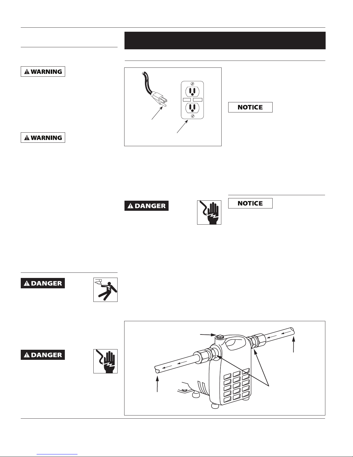
1. A ground fault circuit interrupter
(GFCI) is required.
Extension Cord Length Table
Wire Size #18 #16 #14 #12
Length 25 ft 50 ft 100 ft 150 ft
5. The inlet line may be galvanized
pipe, plastic pipe, or reinforced hose.
Small leaks in suction line greatly
reduce efficiency of pump and may
RESET
TEST
GROUNDING
BLADE
Figure 1
GFCI
RECEPTACLE
2. This pump operates on 115V, 60 Hz
AC, single phase or 115V DC.
3. Use an extension cord only if
necessary. Follow the Extension Cord
Length Table for proper gage of
3-wire, grounding type extension
cord.
Risk of fatal electrical shock.
NEVER cut off the round
grounding prong. Cutting the
cord or plug WILL void the warranty and
make the pump inoperable.
4. Figure 2 shows a typical installation.
Threaded adapters are furnished
for attaching garden hose where
conditions permit its use. In no case
should the pump be more than
15 feet above or away from water
source. Install a foot valve when
suction lift is over 10 feet or when
suction line is over 10 feet long.
prevent priming.
Ordinary garden
hose WILL collapse
under suction pressure and SHOULD
NOT be used for the inlet line, except in
pressure boosting applications.
6. Use a strainer when pumping from a
creek, pond, or source where foreign
objects may be sucked into the
pump. The strainer should prevent
solids from entering the inlet line.
7. A regular garden hose may be used
as a discharge line.
Operation
Pump must be filled
with water before
operation. Running the pump dry WILL
cause damage to the shaft seal.
1. This unit is not waterproof or
weatherproof and is not intended
to be used in showers, saunas, or
other potentially wet locations.
The motor is designed to be used
in a clean, dry location with access
to adequate cooling air. Ambient
temperatures around the motor
should not exceed 104˚F (40˚C).
2. Remove priming plug and fill with
water. Replace plug (plumbers seal
tape should be used on priming plug
to prevent air leaks).
PRIME PLUG
Risk of electrical shock!
This pump is supplied with
a grounding conductor and
grounding type attachment plug. A
grounded receptacle in conformance
with current NEC and local codes must
be used (See Figure 1).
www.waynepumps.com
INLET
HOSE ADAPTERS
OUTLET
Figure 2
2
Page 3
PC4, PC4K
Operation (Continued)
3. Plug power cord into GFCI
protected electrical outlet. The
pump will prime in a few minutes
depending on suction line length.
Use of foot valve on suction line is
recommended.
4. In the case of pressure boosting,
turn water on before starting pump.
This force primes the pump. Then,
plug power cord into GFCI protected
electrical outlet.
5. Unplug cord to turn unit off.
Maintenance
Let pump cool for
at least 20 minutes
before attempting to service. Motor
MAY be extremely hot. Personal injury
MAY result.
1. Pump should be checked periodically
for proper operation.
ALWAYS disconnect
the electrical supply
before attempting to operate, service,
or perform any maintenance. If the
power source is out of sight, lock and
tag in the open (off) position to prevent
unexpected power application. Failure
to do so WILL result in fatal electrical
shock. Only qualified electricians
SHOULD repair this unit. Improper repair
WILL result in fatal electrical shock.
BRUSH REPLACEMENT
Brushes for this
pump SHOULD be
inspected after 100 hours of operation.
Pumps with excess of 100 hours of
operation may stop operating or fail to
start. This could be due to worn brushes
or carbon build-up. The brushes should
be removed and carbon removed.
Worn brushes are not covered under
warranty. Replacement brushes may
be available from WAYNE Pumps. Call
1-800-237-0987 to order.
1) Disconnect electrical cord from
power supply.
2) Remove brush caps with screwdriver.
3) Remove old brush assembly.
4) Insert new brush assembly.
5) Replace brush caps.
For other problems, consult
troubleshooting chart.
ADDITIONAL REPAIRS
To replace bearings, shaft seal, or
gaskets, follow the instructions listed
below.
1. Disconnect electrical cord from
power supply.
2. Relieve pressure in system.
3. Disconnect inlet and outlet lines.
4. Empty water from pump housing.
5. Place pump on bench with motor
end up and remove brushes as
described in BRUSH REPLACEMENT
instructions. If brushes are to be
reused, mark the location from
which each came. Replace brushes
in original orientation upon
completion of repair.
6. Remove the four cap screws holding
motor housing and pump housing
together. Motor housing is now free
and can be removed. Take care not
to lose commutator bearing finger
spring.
7. With a screwdriver, pry the rotorbackhead assembly out of the pump
housing.
8. Remove the impeller by turning
counter clockwise (righthand thread
on shaft).
9. Remove backhead (the bearing is
press fit into the backhead).
10. Place backhead on flat surface with
impeller side down and press out
shaft seal.
11. Place impeller on flat surface
with vane side down and with
screwdriver and hammer break
ceramic seal ring into several pieces
and remove. Next, remove rubber
seal ring cup from impeller.
12. Remove bearing from armature
shaft (press-fit on shaft). (Impeller
side bearing is the only serviceable
bearing).
13. Inspect the armature commutator
bars. The environment in which
the unit has been operating will
have influence on the condition of
the commutator. Airborne dust an
dirt will accelerate wear. A rough
or scarred appearance may dictate
having commutator reconditioned
before reassembly.
14. To reassemble, install new bearing
on the shaft. Always press against
the inner race to prevent bearing
damage. Make sure bearing is tight
against the shaft shoulders.
15. Press shaft seal into backhead.
When pressing shaft seal into place,
apply force to the cup flange. Avoid
touching the polished seal surface;
oil or scratches on this surface may
cause premature failure of the seal.
16. Press ceramic side of seal into
impeller, ceramic side out. Avoid
touching ceramic with hands as oil
may cause premature failure of the
seal. Wipe oil off both sides of seal
with a soft, lint-free cloth.
17. Reassemble unit in reverse order,
beginning with Step 9.
18. After reassembly check shaft for
free rotation with screwdriver in fan
through air exit openings.
www.waynepumps.com
3
Page 4

Operating Instructions and Parts Manual
Troubleshooting Chart
Symptom Possible Cause(s) Corrective Action
Pump will not start or run 1. Blown fuse 1. If blown, replace with proper sized fuse or
reset breaker
2. Low line voltage 2. Contact an electrician
3. Worn brushes 3. Replace brushes
4. Impeller blocked 4. Remove blockage
5. Defective motor 5. Replace pump
Pump will not prime or
retain prime after operating
Flow rate is too low 1. Piping or hose is fouled or damaged 1. Clean or replace
Seal leaks 1. Worn seal 1. Replace seal
Thermal Protector Tripping 1. Damage or misalignment causing
1. Air leak in suction line 1. Repair or replace suction line (use plumbers
tape to install garden hose adpater fittings
and priming plug onto pump body)
2. Impeller blocked 2. Remove blockage
3. Worn seal 3. Replace seal
4. Suction lift too high 4. Lower pump
5. Hose kinked or looped 5. Straighten hose
6. Fittings not tight 6. Tighten fittings
7. Suction hose out of water 7. Submerge suction hose end
8. Clogged inlet 8. Clean inlet
2. Low line voltage 2. Contact an electrician
2. Backhead damaged or cracked 2. Replace backhead
3. Pump head loose on motor 3. Insure proper assembly and no obstruction,
tighten bolts
1. Take to motor repair shop or locate and
rotating parts to bind
2. High surrounding temperature 2. Provide a shaded, well-ventilated area for
3. Low line voltage 3. Contact an electrician
4. Motor housing air-vents blocked 4. Remove air-vent blockage
repair mechanical binding
pump
www.waynepumps.com
4
Page 5
PC4, PC4K
For Replacement Parts or Technical Assistance,
Call 1-800-237-0987
Please provide following information: Address any correspondence to:
- Model number WAYNE Water Systems
- Serial number (if any) 101 Production Drive
- Part description and number as shown in parts list Harrison, OH 45030 U.S.A.
5, 8
2
3
4,8
8
FINGER SPRING
4,8
4, 7,8
7
2
5
5
5
3
6
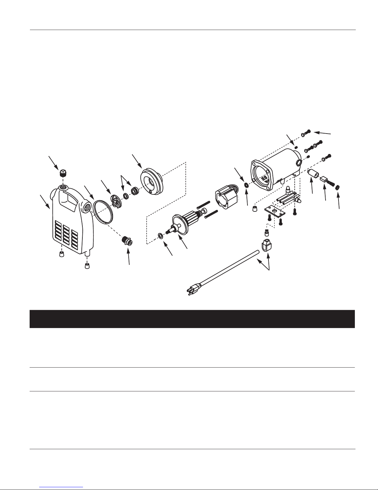
Replacement Parts List
Ref.
No.
1 Brush kit 62007-002 1
2 Brush and holder kit 62008-002 1
3 Fittings kit 62009-001 1
4 Impeller and seal kit 62010-001 1
5 Bearing kit 62011-002 1
6 Cord kit 62012-001 1
7 Volute kit 62013-001 1
8 Backhead kit 62026-001 1
Note: Replacement parts are available in kit form only
Description Part Number Qty.
PAR
7
1, 2
1, 2
www.waynepumps.com
5
Page 6

Operating Instructions and Parts Manual
Limited Warranty
For one year from the date of purchase, WAYNE Water Systems ("WAYNE") will repair or replace, at its option, for the
original purchaser any part or parts of its Sump Pumps or Water Pumps (“Product”) found upon examination by WAYNE to be
defective in materials or workmanship. Please call WAYNE (800-237-0987) for instructions or see your dealer. Be prepared to
provide the model number when exercising this warranty. All transportation charges on Products or parts submitted for repair
or replacement must be paid by purchaser.
This Limited Warranty does not cover Products which have been damaged as a result of accident, abuse, misuse, neglect,
improper installation, improper maintenance, or failure to operate in accordance with WAYNE's written instructions.
THERE IS NO OTHER EXPRESS WARRANTY. IMPLIED WARRANTIES, INCLUDING THOSE OF MERCHANTABILITY AND
FITNESS FOR A PARTICULAR PURPOSE, ARE LIMITED TO ONE YEAR FROM THE DATE OF PURCHASE. THIS IS THE
EXCLUSIVE REMEDY AND ANY LIABILITY FOR ANY AND ALL INDIRECT OR CONSEQUENTIAL DAMAGES OR EXPENSES
WHATSOEVER IS EXCLUDED.
Some states do not allow limitations on how long an implied warranty lasts, or do not allow the exclusions or limitations of
incidental or consequential damages, so the above limitations might not apply to you. This limited warranty gives you specific
legal rights, and you may also have other legal rights which vary from state to state.
In no event, whether as a result of breach of contract warranty, tort (including negligence) or otherwise, shall WAYNE or its
suppliers be liable for any special, consequential, incidental or penal damages including, but not limited to loss of profit or
revenues, loss of use of the products or any associated equipment, damage to associated equipment, cost of capital, cost of
substitute products, facilities, services or replacement power, downtime costs, or claims of buyer’s customers for such damages.
You MUST retain your purchase receipt along with this form. In the event you need to exercise a warranty claim, you MUST
send a copy of the purchase receipt along with the material or correspondence. Please call WAYNE (800-237-0987) for return
authorization and instructions.
DO NOT MAIL THIS FORM TO WAYNE. Use this form only to maintain your records.
MODEL NO. _____________________ SERIAL NO. ________________________ INSTALLATION DATE _____________________
ATTACH YOUR RECEIPT HERE
www.waynepumps.com
6
Page 7

Instructions D’utilisation et Manual de Pièces PC4, PC4K
Veuillez lire et conserver ces instructions. Lire attentivement avant de commencer à assembler, installer, faire fonctionner ou entretenir
l'appareil décrit. Protégez-vous et les autres en observant toutes les informations sur la sécurité. Négliger d'appliquer ces instructions peut
résulter en des blessures corporelles et/ou en des dommages matériels ! Conserver ces instructions pour références ultérieures.
Pompe à Auto-Amorçage
Portative, Tout Usage
Description
La pompe à auto-amorçage tout usage est
conçue pour être utilisée comme pompe de
transfert pour les applications tels que vider
les chauffe-eau, les réservoirs pour bétail,
etc. La pompe peut aussi être utilisée pour
élever la pression d’une façon intermitente
pour des applications tels que le lavage
d’autos et ne nettoyage d’entrées, etc. Le
moteur est refroidi à l’air, il n’est pas conçu
pour fonctionner sous l’eau.
NOTE: Cette pompe n’est pas conçue pour
une installation permanente ou pour
des périodes continues de travail long et
prolongé.
Déballage
Après avoir déballé la pompe utilitaire,
l’inspecter attentivement pour tout
signe de dommage susceptible de s'être
produit en transit. Vérifier la présence
de pièces desserrées, manquantes ou
endommagées. Si vous avez besoin
d’aide, appeler le service à la clientèle
au 1-800-237-0987.
Directives de Sécurité
Ce manuel contient de l’information
très importante de connaître et de
savoir qui est fournie pour la SÉCURITÉ
et pour ÉVITER LES PROBLÈMES
D’ÉQUIPEMENT. Rechercher les symboles
suivants pour cette information.
DANGER indique
une situation
hasardeuse imminente qui RESULTERA
en perte de vie ou blessures graves.
AVERTISSEMENT
indique une
situation hasardeuse potentielle
qui PEUT résulter en perte de vie ou
blessures graves.
ATTENTION indique
une situation
hasardeuse potentielle qui PEUT résulter
en blessures.
AVIS indique de
l’information
importante pour ÉVITER le dommage de
l’équipement.
REMARQUE : Informations qui doivent
retenir tout particulièrement votre
attention.
Généralités Sur La
Sécurité
PROPOSITION 65 DE CALIFORNIE
Ce produit ou son
cordon peuvent
contenir des produits chimiques qui, de
l’avis de l’État de Californie, causent le
cancer et des anomalies congénitales ou
autres problèmes de reproduction. Lavezvous les mains après la manipulation.
RÈGLES DE SÉCURITÉ GÉNÉRALES
NE PAS submerger
le moteur ni le
laisser exposé à l'eau. Danger de
blessures et/ou de mort.
NE PAS pomper les fluides
explosifs tels que l’essence,
l’huile à chauffage, le
kérosène etc. Ne pas utiliser dans un
atmosphère inflammable et/ou explosif.
La pompe DOIT être utilisée seulement
pour pomper de l'eau propre. Danger de
blessures et/ou de mort.
Risque de secousse
électrique. TOUT
le câblage doit être effectué par un
électricien qualifié.
NE PAS marcher dans un
endroit humide avant d’avoir
intégralement coupé le
courant. Le non-respect de cette mise
en garde MÈNERA à un choc électrique
mortel.
1. Lire toutes les instructiions avant de
faire fonctionner le modèle.
2. Débrancher la source de puissance et
dissiper toute la pression du système
Spécifications
Moteur. . . . . . . . . . . . . Monophasé - 115V, 60 Hz, 8,000 tr/min
Moteur. . Moteur En Série (ype balai) Fonctionnement c.a./c.c.
Turbine. . . . . . . . . . . . . . . . . . . . . . . . . . . . . . . .Thermoplastique
Carter de Moteur . . . . . . . . . . . . . . . . . . . . . . . . . . . . . . . . Fonte
Arbre et Joint de Volute. . . . . . . . . . . . . . . . . . . . . . . . . .Buna-N
Température Max. de Fluide . . . . . . . . . . . . . . . . . . . . . . . . 49ºC
MÉMENTO: Gardez votre preuve datée d'achat à fin de la garantie!
Joignez-la à ce manuel ou classez-la dans un dossier pour plus de sécurité.
© 2011, WAYNE/Scott Fetzer Company. 321305-001 12/11
Puissance . . . . . . . . . . . . . . . . . . . . . . . . . . . . . . . . . . . . . . 1/2 HP
Ouvertures Arrivée/Sortie. . . . . . . . . . . . . . . . . . . . . 3/4 po NPT
Carter de Pompe. . . . . . . . . . . . . . . . . . . . . . . . . . . . . . . . .Fonte
Arbre du Moteur. . . . . . . . . . . . . . . . . . . . .Acier laminé à froid
Palier du Moteur. . . . . . . . . . . . . . . . . .Graissé en permanance
Roulements de l'élément mobile
7-Fr
Page 8

Instructions D’utilisation et Manual de Pièces
Généralités Sur La
Sécurité (Suite)
avant de procéder à l’entretien de
n’importe quelle pièce détachée.
3. Purger tout le liquide du système
avant de procéder à l’entretien.
Bien fixer la
conduite de
décharge avant de démarrer la pompe.
Toute conduite de décharge mal fixée
PEUT faire l’effet d’un fouet. Des
blessures et/ou des dommages à la
propriété POURRAIENT en résulter.
4. Inspecter la pompe et les pièces
détachées de temps en temps pour
rechercher des tuyaux faibles et usés.
S’assurer que toutes les connexions
soient sûrs.
Le moteur de la
pompe est doté d'un
protecteur thermique à réinitialisation
automatique qui POURRAIT redémarrer
de manière imprévue. Le déclenchement
du protecteur est une indication
de surcharge du moteur causée par
une utilisation de la pompe à faible
hauteur de chute (restriction de faible
décharge), d'une tension excessivement
haute ou basse, d'un câblage inadéquat,
de la température excessive de l'air
ambiant, d'une ventilation inadéquate,
et/ou d'un moteur ou d'une pompe
défectueuse.
5. Fournir un moyen de dissiper la
pression dans le cas d’une ligne de
décharge obstruée.
6. Protéger le cordon d’alimentation
des objets pointus, surfaces chaudes,
d’huile et de produits chimiques.
Ne pas tortiller le cordon et
remplacer les cordons endommagés
immédiatement.
Installation
Tableau De Longueur De Cordons Prolongateurs
Taille de fils #18 #16 #14 #12
Longueur 8 m 15 m 31 m 45 m
conditions permettent son usage.
La pompe ne doit jamais se situer
à plus de 4,6 m (15 pi) au-dessus
ou à distance d'une source d'eau.
TEST
RESET
Installer un clapet de pied lorsque le
montage d'aspiration ou conduite
d'aspiration dépassent 3 m (10 pi) de
long.
BROCHE DE MISE À
LA TERRE
Figure 1
d’une borne de terre. Une prise de courant
qui se conforme aux codes NEC et locaux
doit être utilisée (Voir Figure 1).
PRISE DDFT
2. Cette pompe fonctinne sur un circuit
de 115V, 60 Hz c.a., monophasé ou
115Vc.c.
3. Utiliser un cordon prolongateur
seulement si nécessaire. Consulter
le Tableau de Longueur De Cordon
Prolongateur pour la taille correcte
de cordon prolongateur de type à 3
fils mis à la terre.
5. La conduite d'entrée peut être
constituée de tuyau galvanisé, en
plastique ou renforcé. Les petites
fuites dans la conduite d'aspiration
réduisent grandement l'efficacité
de la pompe et peuvent même
empêcher l'amorçage.
Les boyaux
d'arrosage
courants S'ÉCRASERONT sous la
pression d'aspiration et NE DOIVENT
par conséquent PAS être utilisés dans
le conduit d’entrée excepté pour
augmenter la pression.
6. Utiliser un filtre lorsque vous
pompez de l’eau d’un ruisseau, d’un
étang ou d’une source où des objets
étranges peuvent être aspirés dans
Risque de choc électrique
mortel. NE JAMAIS couper
la broche de terre ronde.
La coupure du cordon ou de la fiche
ANNULERA la garantie et rendrait la
pompe inutilisable.
la pompe. Le filtre devrait empêcher
les solides d’entrer la ligne d’arrivée.
7. Un boyeau d’arrosage ordinaire
peut être utilisé comme ligne de
décharge.
4. La figure 2 démontre une
installation typique. Des adaptateurs
filetés sont fournis pour attacher
un boyeau d’arrosage là où les
TOUJOURS débrancher la
source de courant avant
toute mise en marche,
réparation, ou entretien de la pompe.
NE JAMAIS manipuler de pompe avec
les mains humides ou debout sur une
surface humide ou dans l'eau. Il en
RÉSULTERA un choc électrique mortel.
1. Un interrupteur DDFT est exigé.
Risque de secousse électrique
mortelle! Cette pompe est
fournie d’un fil de terre et
BOUCHON D’AMORÇAGE
SORTIE
Figure 2
ARRIVÉE
ADAPTATEURS DE
TUYAUX
8-Fr
Page 9

PC4, PC4K
Fonctionnement
La pompe doit être
remplie d’eau avant
le fonctionnement. Le fait de faire
tourner la pompe à sec ENDOMMAGERA
le joint d'étanchéité de l'arbre.
1. Ce modèle n’est pas imperméable
ni intempérisé et n’est pas conçu
pour l’utilisation dans les douches,
les saunas, ou autres endroits qui
peuvent être trempes. Le moteur
est conçu pour l’utilisation dans un
endroit propre et sêche qui a accès
à sufisamment d’air refroidissant. La
température ambiante autour du
moteur ne devrait pas dépasser 40ºC
(104ºF).
2. Enlever le bouchon d’amorçage et
remplir avec de l’eau. Remplacer
le bouchon (du ruban d'étanchéité
de plombier doit être utilisé sur le
bouchon de remplissage pour éviter
les fuites d'air).
3. Brancher le cordon d’alimentation
dans une prise de courant protégée
DDFT. La pompe s’ammorçera
dans quelques minutes selon la
longueur de la ligne d’aspiration.
Il est recommandé que vous
utilisez un clapet à pied sur la ligne
d’aspiration.
4. Pour une augmentation de pression,
faire couler l’eau avant de démarrer
la pompe. Ceci ammoce la pompe
avec pression. Ensuite, brancher le
cordon d’alimentation dans une
prise de courant protégée, DDFT.
5. Débrancher le cordon pour mettre le
modèle hors circuit.
Entretien
Permettre que
la pompe se
refroidisse pendant au moins 20
minutes avant de procéder à l’entretien.
Le moteur POURRAIT être extrêmement
chaud. Des blessures PEUVENT en
résulter.
1. Vérifier la pompe de temps en temps
pour un fonctionnement correct.
TOUJOURS
débrancher
l'alimentation électrique avant
toute mise en marche, réparation,
ou entretien. Si la source de courant
n’est pas visible, la verrouiller et
l’identifier en position ouverte (arrêt)
pour éviter toute alimentation de
courant imprévue. Le non-respect de
ces instructions MÈNERA à un choc
électrique mortel. Seuls les électriciens
qualifiés SONT HABILITES à réparer
cet appareil. Une mauvaise réparation
MÈNERA à un choc électrique mortel.
REMPLACEMENT DES BALAIS
Les brosses de cette
pompe DOIVENT
faire l’objet d’une inspection au bout de
100 heures de fonctionnement.
Les pompes qui fonctionnent pour
plus que 100 heures peuvent cesser de
fonctionner ou ne pas se démarrer. Ceci
peut être causé par des balais usés ou
l’accumulation de carbone. Enlever les
balais et nettoyer le carbone des balais.
Les balais usés ne sont pas couverts sous
la garantie. Les balais de rechange sont
disponibles de la division de pompes
WAYNE. Composer 1-800-323-0620 pour
les commander.
1) Débrancher le cordon d’alimentation
de la source de puissance.
2. Enlevver les capots de balais avec un
tournevis
3. Enlever le vieux montage de balai.
4. Introduire le nouveau montage de
balai.
5. Remplacer les capots du balai.
Consulter le guide de dépannage
concernant d’autres problèmes.
RÉPARATIONS ADDITIONNELLES
Pour remplacer les roulements, joint
d'étanchéité de l'arbre, ou joints
d'étanchéité, suivre les instructions
indiquées plus bas.
1. Débrancher le cordon d’alimentation
de la source de puissance.
2. Dissiper la pression du système.
3. Débrancher les lignes d‘arrivée et de
sortie.
4. Purger l’eau du carter de la pompe.
5. Placer la pompe sur un banc avec
le côté du moteur faisant face en
haut et enlever les balais comme
décrit dans lles instructions de
REMPLACEMENT DES BALAIS.
Si vous allez utiliser les balais de
nouveau, inscrire l’endreoit d’où
vous les avez enlevés. Remplacer
les balais dans leur positions
originels lorsque vous complétez la
réparation.
6. Enlever les quatre vis d’assemblage
qui tiennent le carter du moteur et
le carter de la pompe ensembles.
Le carter du moteur est maintenant
libre et peut être enlevé. S’assurer
de ne pas perdre le ressort de doight
du roulement de commutateur
desserré.
7. Avec un tournevis, enlever
le montage de rotor-plaque
d’étanchéité du carter de la pompe.
8. Enlever la turbine en tournant au
sens contraire des aiguilles d’une
montre (filet droit sur l’arbre).
9. Enlever la plaque d’étanchéité
(le palier est fixé dans la plaque
d’étanchéité).
10. Placer la plaque d’étanchéité sur
une surface plate avec le côté de
la turbine faisant face en bas et
pousser le joint d’arbre.
11. Placer la turbine sur une surface
plate avec le côté des ailettes faisant
face en bas et avec un tournevis
et un marteau, casser la bague
d’étanchéité en céramique en
plusieurs morceaux et les enlever.
Ensuite,enlever le godet de la bague
d’étanchéité en caoutchouc de la
turbine.
12. Retirer les roulements de l'arbre
d'induit (ajustage à pression sur
l'arbre). (Le roulement du côté
de l'impulseur constitue le seul
roulement réparable).
13. Inspecter les lames de collecteurs
d’induit. L’environnement dans
lequel le modèle fonctionnait
influencera l’état du commutateur.
La poussière et la saleté dans l’air
accèlera l’usage. Une apparence
rugueuse ou avec cicatrices peut
nécessiter la remise en état du
commutateur avant le remontage.
14. Pour remonter, installer le nouveau
roulement sur l'arbre. Toujours
presser contre la face intérieure
pour éviter d'endommager les
roulements. S'assurer que le
roulement est serré contre les
épaulements d'arbre.
9-Fr
Page 10

Instructions D’utilisation et Manual de Pièces
Entretien (Suite)
15. Appuyer le joint d’arbre dans la
plaque d’étanchéité. Lorsque vous
appuyez sur le joint d’arbre, forcer
le godet de la bride. Ne pas toucher
la surface polie du joint; de l’huile
ou des égratignures sur cette surface
peuvent causer la faillite du joint.
16. Pousser le côté céramique du joint
dans la turbine, le côté céramique
vers l’extérieur. Ne pas toucher le
céramique avec vos mains, l’huile
peut causer la faillite prématurée du
joint. Essuyer l’huile des deux côtés
du joint avec un torchon souple sans
charpie.
17. Remonter le modèle en ordre
contraire de l’étape 9.
Notes
18. Suite au remontage, vérifier que
l’arbre tourne librement avec un
tournevis dans l’évantail à travers les
ouvertures de sortie.
10-Fr
Page 11

Série En Fonte Tout Usage
Guide de Dépannage
Symptôme(s) Cause(s) Possible(s) Mesures Correctives
La pompe ne se démarre pas
et ne fonctionne pas
La pompe ne s’ammorce
pas ou ne conserve pas
l’ammorçage suite au
fonctionnement
Taux de débit trop bas 1. La tuyauterie ou les tubes sont souillis
Fuites dans les joints 1. Joint usé 1. Remplacer le joint
Déclenchement du protecteur
thermique
1. Fusible sauté 1. Si sauté, remplacer avec un fusible de
taille correcte ou enclencher à nouveau le
disjoncteur
2. Tension de ligne basse 2. Communiquer avec un électricien
3. Balais usés 3. Remplacer les balais
4. Turbine obstruée 4. Enlever le blocage
5. Moteur défectueux 5. Remplacer la pompe
1. Fuite d’air dans la ligne d’aspiration 1. Réparer ou remplacer la ligne d’aspiration
(utiliser du ruban d'étanchéité de plombier
pour installer les raccords d'adaptateur et
le bouchon de remplissage sur le corps de
pompe).
2. Turbine obstruée 2. Enlever le blocage
3. Joint usé 3. Remplacer le joint
4. La hauteur d’aspiration trop élevée 4. Baisser la pompe
5. Tuyau en coude ou bouclé 5. Redressir le tuyau
6. Raccords desserrés 6. Serrer les raccords
7. Tuyau d’aspiration hors de l’eau 7. Submerger le bout du tuyau d’aspiration
8. Arrivée obstruée 8. Nettoyer l’arrivée
1. Nettoyer ou remplacer
ou endommagés
2. Tension de ligne basse 2. Communiquer avec un électricien
2. Tête arrière endommagée ou fissurée 2. Remplacer la tête arrière
3. La tête de la pompe desserrée du
moteur
1. Endommagement ou défaut
d'alignement provoquant un grippage
des pièces mobiles
2. Température ambiante élevée 2. Mettre la pompe dans un endroit ombragé
3. Basse tension de ligne 3. Communiquer avec un électricien
4. Évents du boîtier moteur bloqués 4. Retirer le blocage des évents
3. Assurer le montage correct sans
obstructions, serrer les boulons
1. L’emporter dans un atelier de réparation de
moteurs ou localiser et réparer le grippage
mécanique
et bien ventilé
11-Fr
Page 12

Instructions D’utilisation et Manual de Pièces
5, 8
Pour pièces de rechange ou assistance technique,
appeler 1-800-237-0987
S’il vous plaît fournir l’information suivante: Adresser toute correspondance à :
- Numéro de Modèle WAYNE Water Systems
- Numéro de série (si présent) 101 Production Drive
- Description et numéro de la pièce Harrison, OH 45030 U.S.A.
2
4,8
8
RESSORT AU
DOIGT
3
4,8
7
4, 7,8
7
2
1, 2
5
1, 2
5
5
3
6
Liste de pièces de rechange
N°. de
réf.
1 Nécessaire de balai 62007-002 1
2 Trousse de porte-brosses 62008-002 1
3 Nécessaire de raccords 62009-001 1
4 Nécessaire de turbine et de joint 62010-001 1
5 Nécessaire de roulements 62011-002 1
6 Nécessaire de cordon 62012-001 1
7 Nécessaire de volute 62013-001 1
8 Nécessaire plaque joint étanche 62026-001 1
Remarque: Les pièces de rechange sont disponibles en nécessaires seulement.
12-Fr
PAR
Numéro de
piéceDescription Qté.
Page 13

Notes
PC4, PC4K
13-Fr
Page 14

Instructions D’utilisation et Manual de Pièces
Garantie Limitée
Pour un an à compter de la date d’achat, WAYNE Water Systems ("WAYNE") vas réparer ou remplacer, à son option, pour
l’acheteur originel n’importe quelle pièce ou pièces de ces Pompes De Puisard ou Pompes À Eau (“Produit”) déterminées
défectueuses, par WAYNE, en matière ou en fabrication. S’il vous plaît appeler WAYNE (800-237-0987) pour des instructions ou
contacter votre marchand. S’assurer d’avoir, à votre disposition, le numéro du modèle afin d’effectuer cette garantie. Les frais
de transportation des Produits ou pièces soumis pour la réparation ou le remplacement sont la responsabilité de l’acheteur.
Cette Garantie Limitée ne couvre pas les Produits qui se sont fait endommagés en résultat d’un accident, utilisation abusive,
mauvais usage, négligence, l’installation incorrecte, entretien incorrect, ou manque d’utilisation conformément aux
instructions écrit de WAYNE.
IL N’EXISTE AUCUNE AUTRE GARANTIE OU AFFIRMATION. LES GARANTIES EXPRIMÉES, Y COMPRIS CELLES DE
COMMERCIALISABILITÉ ET D’ADAPTION À UNE FONCTION PARTICULIÈRE, SONT LIMITÉES À UN AN À COMPTER DE LA
DATE D’ACHAT. CECI EST LA REMÈDE EXCLUSIVE ET N’IMPORTE QUELLE RESPONSABILITÉ POUR N’IMPORTE QUEL ET
TOUT DOMMAGES INDIRECTS OU DÉPENSES QUOI QUE SE SOIT EST EXCLUS.
Certaines Provinces n’autorisent pas de limitations de durée pour les garanties implicites, ni l’exclusion ni la limitation des
dommages fortuits ou indirects. Les limitations précédentes peuvent donc ne pas s’appliquer. Cette garantie limitée donne, à
l’acheteur, des droits légales précis, et vous pouvez avoir autres droits légales qui sont variable d’une Province ou d’un État à
l’autre.
En aucun cas, soit par suite d’un rupture de contrat de garantie, acte dommageable (y compris la négligence) ou autrement,
ni WAYNE ou ses fournisseurs seront responsables pour aucune dommage spéciale, incidentel ou pénal, y compris, mais pas
limité à la perte de profits ou recettes, la perte d’usage des produits ou n’importe quel équipement associé, dommage à
l’équipement associé, coût de capital, coût de produits remplaçants, aménagements, services ou abilité de remplaçement, coût
de temps que le produit n’est pas en service, ou la réclamation des clients de l’acheteur pour ces dommages.
Vous DEVEZ garder votre recette d’achat avec ce bulletin. Il est NÉCESSAIRE d’envoyer une copie de la recette d’achat avec
le matériel ou correspondance afin d’effectuer une réclamation de la garantie. S’il vous plaît appeler WAYNE (800-237-0987)
pour l’autorisation et instructions concernant le renvoi.
NE PAS ENVOYER, PAR LA POSTE, CE BULLETIN À WAYNE. Utiliser ce bulletin seulement pour vos archives.
Nº DU MODÈLE _____________________ Nº DE SÉRIE ________________________ DATE D’INSTALLATION _____________________
FIXER VOTRE FACTURE ICI
14-Fr
Page 15

Manual de instrucciones de operación y piezas PC4, PC4K
Por favor lea y guarde estas instrucciones. Léalas cuidadosamente antes de tratar de montar, instalar, operar o dar mantenimiento al producto
aquí descrito. Protéjase usted mismo y a los demás observando toda la información de seguridad. ¡El no cumplir con las instrucciones puede
ocasionar daños, tanto personales como a la propiedad! Guarde estas instrucciones para referencia en el futuro.
Bomba Portátil de
Servicio con Sistema de
Cebado Automático
Descripción
Las bombas portátiles de servicio con
sistema de cebado automático están
diseñadas para usarse como bombas de
desagüe para vaciar calentadores de agua,
tanques para animales, etc. Igualmente,
las bombas se pueden usar de modo
intermitente para lavar coches, limpiar
entradas de garajes, etc. El motor se enfría
con aire y no está diseñado para operar
bajo agua.
NOTA: Este bomba no está diseñada
para una instalación permanente o para
períodos de trabajo continuo largos y
extendidos.
Para Desempacar
Después de desempacar la bomba
de uso general, inspecciónela
cuidadosamente para detectar cualquier
daño que pueda haber ocurrido
durante el transporte. Verifique que no
haya piezas sueltas, dañadas o faltantes.
Si necesita asistencia, llame a nuestro
Departamento de Servicio al Cliente al
1-800-237-0987.
Medidas de Seguridad
Este manual contiene informacion
que es muy importante que sepa
y comprenda. Esta informacion se
la suministramos como medida de
SEGURIDAD y para EVITAR PROBLEMAS.
CON EL EQUIPO. PELIGRO le indica
que hay
una situación inmediata que le
OCASIONARÍA la muerto o heridas de
gravedad.
ADVERTENCIA le
indica que hay una
situación que PODRÍA ocasionarle la
muerte o heridas de gravedad.
PRECAUCION le
indica que hay
una situación que PODRÍA ocasionarle
heridas no muy graves.
AVISO le indica
una información
importante, que de NO seguirla, le
PODRÍA ocasionar daños al equipo.
NOTA: Información que requiere
atención especial.
Informaciones
Generales de Seguridad
PROPOSICIÓN 65 DE CALIFORNIA
Este producto, o su
cordón eléctrico,
puede contener productos químicos
conocidos por el estado de California
como causantes de cáncer y defectos de
nacimiento u otros daños reproductivos.
Lave sus manos después de usar.
SEGURIDAD GENERAL
NO sumerja el motor
ni permita que el
motor esté expuesto al agua. CAUSARÁ
lesiones corporales y/o la muerte.
NO la use para bombear
fluidos inflamables o
explosivos, como gasolina,
aceite combustible, queroseno, etc. NO
la use en una atmósfera inflamable o
explosiva. La bomba sólo DEBE usarse
para bombear agua limpia. CAUSARÁ
lesiones corporales y/o la muerte.
Peligro de
electrocutamiento.
Un electricista calificado debe realizar
TODO el cableado.
NO camine sobre áreas
húmedas sino después de
que TODAS las fuentes
de electricidad estén apagadas. El
desobedecer esta advertencia CAUSARÁ
un choque eléctrico mortal.
1. Lea todas las instrucciones antes de
comenzar a usar la bomba.
2. Desconecte el cordón eléctrico y libere
toda la presión del sistema antes de
darle servicio a cualquier componente.
Especificaciones
Motor. . . . . . . . . . . . . . .Monofásico - 115V, 60 Hz, 8,000 R.P.M.
Motor. . . . . . . . . . . . . . . . . Serie Wound (con escobillas) CA/CD
Propela. . . . . . . . . . . . . . . . . . . . . . . . . . . . . . . . . . Termoplástico
Cubierta del Motor. . . . . . . . . . . . . . . . . . . . . . . . .Hierro colado
Sellos del eje y la Voluta. . . . . . . . . . . . . . . . . . . . . . . . . .Buna-N
Temp. Máx. del Fluído . . . . . . . . . . . . . . . . . . . . . . .49ºC (120ºF)
RECORDATORIO: ¡Guarde su comprobante de compra con fecha para fines de la garantía!
Adjúntela a este manual o archívela en lugar seguro.
© 2011, WAYNE/Scott Fetzer Company. 321305-001 12/11
Caballos de Fuerza . . . . . . . . . . . . . . . . . . . . . . . . . . . . . . 1/2 CP
Orificios de Entrada/Salida. . . . . . . . . . . . . 19,1 mm (3/4”) NPT
Envoltura de la Bomba. . . . . . . . . . . . . . . . . . . . . Hierro colado
Eje del Motor. . . . . . . . . . . . . . . . . . . . .Acero laminado en frío
Cojinetes del Motor . . . . . . . . . . . . . . . Lubricados de por Vida
Rodamientos de bola
15-Sp
Page 16

Manual de instrucciones de operación y piezas
Informaciones
Generales de Seguridad
(Continuacion)
3. Drene todos los líquidos del sistema
antes de darle servicio.
Asegure la línea de
descarga antes
de dar arranque a la bomba. Si no la
asegura, ES POSIBLE que se sacuda
bruscamente y PODRÍAN causarse
lesiones personales y/o daños a la
propiedad.
4. Periódicamente inspeccione la
bomba y los componentes, chequée
si las mangueras están debilitadas o
desgastadas. Cerciórese de que todas las
conecciones estén bien apretadas.
El motor de la
bomba está
equipado con un circuito protector
térmico de reconfiguración automática
y ES POSIBLE que se reactive
repentinamente. La desconexión
del circuito protector indica un
recalentamiento del motor debido a
que la bomba está funcionando con
presión hidrostática baja (restricción de
descarga baja), voltaje excesivamente
alto o bajo, cableado inadecuado,
temperatura excesiva del aire
circundante, ventilación inadecuada y/o
motor o bomba defectuosos.
5. Cerciórese de que haya una forma de
liberar la presión en caso de que la línea
de descarga se obstruya.
6. Proteja los cordones eléctricos contra
objetos afilados, superficies calientes,
aceite y químicos. Evite que el cordón
se enrolle y reemplace los cordones
dañados inmediatamente.
Instalación
SIEMPRE desconecte la fuente
de energía antes de intentar
operar o reparar la bomba, o
darle mantenimiento. NUNCA manipule
la bomba con las manos húmedas
o cuando se encuentre sobre una
superficie húmeda o mojada, ni dentro
del agua. OCURRIRÁ un choque eléctrico
mortal.
1. Necesita usar un cortacircuito
automático con conexión a tierra.
Tabla de las Longitudes de los Cordones de Extensión
Tamaño del alambre #18 #16 #14 #12
Longitud 8 m 15 m 31 m 45 m
condiciones lo permitan. En ningún
caso la bomba debe colocarse a más
de 4,5 m (15 pies) de distancia o
de altura con respecto a la entrada
TEST
RESET
de agua. Instale una válvula de pie
cuando la altura de succión sea
superior a los 3 m (10 pies) o cuando
la línea de succión tenga más de 3 m
TERMINAL PARA
CONEXIÓN A TIERRA
Figura 1
enchufe para conexión a tierra. Debe
utilizar un tomacorrientes que cumpla con
los códigos vigentes nacionales (NEC en
EE.UU.) y locales (Vea la Figura 1).
TOMACORRIENTES GFCI
(CONECTADO A TIERRA)
2. Esta bomba sólo se debe usar
con circuitos de 115 voltios
(monofásicos), 60 Hz CA, ó 115
voltios CD.
3. Use un cordón de extensión sólo
cuando sea necesario. Use cordones
de extensión, de tres alambres para
conexión a tierra que sean de la
longitud y calibre indicados en la
Tabla de cordones de extensión.
(10 pies) de largo.
5. La línea de entrada puede ser un
tubo galvanizado o de plástico, o
una manguera reforzada. Las fugas
pequeñas en la línea de succión
reducen en gran medida la eficiencia
de la bomba y pueden impedir el
cebado.
Las mangueras de
jardín normales
COLAPSARÁN con la presión de succión;
por lo tanto, NO DEBEN usarse para la
línea de entrada, con excepción de los
sistemas para aumentar la presión.
6. Use un colador cuando vaya a
bombear agua de un riachuelo,
charca o cualquier sitio donde pueda
haber basura que podría obstuir
la bomba. El colador debe evitar
Riesgo de choque eléctrico
mortal. NUNCA corte la clavija
redonda de conexión a tierra.
Si corta el cable o el enchufe, SE ANULARÁ
la garantía y hará que la bomba no
funcione.
la entrada de sólidos a la línea de
entrada de la bomba.
7. Puede usar una manguera común
para jardines como línea de
descarga.
4. La Figura 2 le indica cómo instalar la
bomba. Los adpatadores con roscas
se le suministran para que conecte
mangueras para jardín cuando las
TAPÓN DEL SISTEMA DE
CEBADO
ENTRADA
¡Peligro de morir
electrocutado! Esta bomba
tiene un conductor para
conexión a tierra y un
Figura 2
SALIDA
ADAPTADORES DE
MANGUERA
16-Sp
Page 17

PC4, PC4K
Funcionamiento
Debe llenar la
bomba de agua
antes de encenderla. Hacer funcionar la
bomba en seco CAUSARÁ daños en el
sello del eje.
1. Esta unidad no es a prueba de agua
o a prueba de intemperie y no está
diseñada para usarse en duchas,
saunas, ni ningún sitio donde se
pueda mojar. El motor está diseñado
para usarse en sitios limpios y secos
donde tenga acceso a aire adecuado
para enfriarlo. La temperatura
ambiental alrededor del motor no
debe exceder 40˚C (104˚F).
2. Quítele el tapón al sistema de
cebado y llénelo de agua. Vuelva a
colocar el tapón (se debe usar cinta
de sellado de plomería en el tapón
de cebado para evitar fugas de aire).
3. Conecte el cordón eléctrico a un
tomacorrientes con cortacircuito
automático con conexión a tierra.
La bomba completará el proceso
de cebado en pocos minutos,
dependiendo de la longitud de la
línea de succión. Le recomendamos
que use una válvula de pie en la
línea de succión.
4. En caso de que la vaya a usar para
aumentar la presión de agua, abra
la llave de agua antes de encender
la bomba. La bomba se cebará
con la presión del agua. Después,
conecte el cordón eléctrico a un
tomacorrientes a un tomacorrientes
con cortacircuito automático con
conexión a tierra.
5. Desconecte el cordón para apagar la
unidad.
Mantenimiento
Debe esperar por lo
menos 20 minutos
para que la bomba se enfrie antes de
darle servicio. ES POSIBLE que el motor
esté muy caliente. ES POSIBLE causar
lesiones personales.
1. Debe chequear la boomba
periódicamente para ver si está
funcionando adecuadamente.
SIEMPRE
desconecte el
suministro de corriente antes de
intentar operar, efectuar reparaciones
o realizar cualquier tipo de
mantenimiento. Si la fuente de energía
está fuera de la vista, bloquéela y
etiquétela en la posición abierta (off)
para evitar que se suministre corriente
en forma inesperada. Dejar de hacer
esto CAUSARÁ un choque eléctrico
mortal. Esta unidad DEBE ser reparada
únicamente por electricistas calificados.
La reparación incorrecta CAUSARÁ un
choque eléctrico mortal.
PARA REEMPLAZAR LAS ESCOBILLAS
Las escobillas de
esta bomba DEBEN
inspeccionarse después de 100 horas de
funcionamiento.
Después de 100 horas de
funcionamiento la bomba podría dejar
de funcionar o no encender. Ésto podría
ser debido al desgasto de las escobillas
o a la acumulación de carbón. Debe
desmontarle las escobillas y quitarle
los residuos de carbón. Las escobillas
no están cubiertas en la garantía.
Para ordenar escobillas de repuesto
comuníquese con el distribuidor de
bombas WAYNE más cercano a su
domicilio. En EUA llame al 1-800-3230620 para ordenarlas.
1. Desconecte el cordón eléctrico del
tomacorrientes.
2. Use un desarmador para quitarle las
tapas a las escobillas.
3. Saque el ensamblaje de las escobillas
usadas.
4. Colóquele las escobillas nuevas.
5. Colóquele las tapas de las escobillas.
Si tiene otros problemas, consulte la
guía de diagnóstico de averías
REPARACIONES ADICIONALES
Para reemplazar los rodamientos,
el sello del eje, o las juntas, siga
las instrucciones que se incluyen a
continuación.
1. Desconecte el cordón eléctrico del
tomacorrientes.
2. Libere la presión del sistema.
3. Desconecte las líneas de entrada y de
salida.
4. Vacíe el agua en la envoltura de la
bomba.
5. Coloque la bomba sobre una mesa
con el motor hacia arriba y quítele
las escobillas tal cómo se le indica en
la sección “como reemplazar las
escobillas”. Si va a usar las mismas
escobillas, marque de donde sacó
cada una. Al terminar de hacer las
reparaciones, coloque las escobillas
en su posición original.
6. Quítele los cuatro tornillos que
unen la envoltura del motor a
la de la bomba. La envoltura del
motor estará libre y podrá sacarla.
Cerciórese de que no se extravie el
resorte de los cojinetes.
7. Use un desarmador para sacar la
tapa posterior de la envoltura de la
bomba.
8. Para sacar la propela gírela en
sentido contrario al de las agujhas
del reloj (roscas derechas del eje).
9. Saque la tapa posterior (el cojinete
está calzado a presión a la tapa
posterior).
10. Coloque la tapa posterior sobre una
superficie plana con la propela hacia
abajo y aplíquele presión al sello del
eje para sacarlo.
11. Coloque la propela sobre una
superficie plana con la aleta hacia
abajo y con un desarmador y un
martillo rompa el sello de cerámica
en varios pedazos para sacarlo.
Después, sáquele a la propela el
anillo del sello de goma.
12. Retire el rodamiento del eje del
inducido (colocado a presión en el
eje). (El rodamiento del lado del
impulsor es el único rodamiento que
puede ser reparado por el usuario).
13. Inspeccione las barras conmutadoras
de la armadura. La condición de
éstas dependerá de donde haya
utilizado la bomba. El polvo en
el aire acelerará su desgasto.
Si lucen estar dañadas, deberá
reacondicionar el comutador antes
de reensamblarlo.
14. Para volver a armarlo, instale el
rodamiento nuevo en el eje. Siempre
haga presión contra el aro de
rodamiento interior para evitar que
se dañe el rodamiento. Asegúrese
de que el rodamiento esté ajustado
contra las pestañas del eje.
15. Aplíquele presión al sello del eje
para conectarlo a la tapa posterior.
Para colocarlos aplíquele la presión
a la lengüeta. Evite tocar la
superficie pulida del sello; si esta
superficie se contamina con aceite
o se raya el sello podría dañarse
prematuramente.
17-Sp
Page 18

Manual de instrucciones de operación y piezas
Mantenimiento
(Continuacion)
16. Presione el lado de cerámica del
sello contra la propela, con el lado
de cerámica hacia afuera. Evite tocar
la cerámica con las manos ya que los
residuos de aceite podrían dañar el
sello prematuramente. Limpie los
residuos de aceite de ambos lados
del sello con un trapo suave y sin
hilachas.
17. Para reemsamblar la unidad siga los
pasos anteriores en orden contrario,
comenzando con el paso 9.
18. Después de reensamblar la unidad
introduzca un desarmador por el
orificio de entrada de aire para
verificar que las aletas puedan rotar
libremente.
Tabla de Identificación de Problemas
Síntoma(s) Causa(s) Posible(s) Medida Correctiva(s)
La bomba no se
enciende ni funciona
La bomba no se ceba o
lo pierde después de
funcionar
El flujo es muy bajo 1. Las tuberías o mangueras están
Los sellos tienen fugas 1. El sello está desgastado 1. Reemplace el sello
Desconexión del circuito
protector térmico
1. Un fusible quemado 1. Si está quemado, reemplácelo con un fusible
adecuado o active el cortacircuito
2. El voltaje es muy bajo 2. Póngase en contacto con un electricista
3. Las escobillas están desgastadas 3. Reemplace las escobillas
4. La propela está obstruída 4. Quítele lo que la está obstruyendo
5. El motor está dañado 5. Reemplace la bomba
1. Hay fuga de aire en la línea de succión 1. Repare o reemplace la línea de succión
(use cinta de plomería para instalar en el
cuerpo de la bomba los adaptadores de la
manguera de jardín y el tapón de cebado)
2. La propela está obstruída 2. Quítele lo que la está obstruyendo
3. El sello está desgastado 3. Reemplace el sello
4. El nivel de succión es muy alto 4. Coloque la bomba en un sitio más bajo
5. La manguera está enrollada 5. Enderece la manguera
6. Las conexiones están flojas 6. Apriete las conexiones
7. La manguera de succión no tiene agua 7. Sumerja el extremo de la manguera de
succión
8. El orificio de entrada está obstruído 8. Limpie el orificio de la entrada
1. Límpielas o reemplácelas
obstruídas o dañadas
2. El voltaje es muy bajo 2. Póngase en contacto con un electricista
2. Cabezal dañado o partido 2. Cambie el cabezal
3. La bomba está mal conectada al motor 3. Cerciórese de que esté bien conectada y que
no esté obstruída, apriete los pernos
1. Daño o desalineación que hace que las
piezas giratorias se atasquen
2. Temperatura circundante alta 2. Proporcione un área con sombra y bien
3. Bajo voltaje de la línea 3. Póngase en contacto con un electricista
4. Agujeros de ventilación de la caja del
motor bloqueados
1. Lleve el motor al taller de reparaciones o
ubique y repare el atascamiento mecánico
ventilada para la bomba
4. Quite el bloqueo de los agujeros de
ventilación
18-Sp
Page 19

PC4, PC4K
5, 8
Para Ordenar Repuestos o Asistencia Técnica, Sírvase
Llamar al Distribuidor Más Cercano a Su Domicilio
Sirvase darnos la siguiente información: Dirija toda la correspondencia a:
- Número del modelo WAYNE Water Systems
- Código impreso 101 Production Drive
- Descripción y número del repuesto según la lista Harrison, OH 45030 U.S.A.
de repuestos
2
3
4,8
4, 7,8
7
8
RESORTE DE
RETENCIÓN
4,8
2
5
5
5
3
6
7
1, 2
1, 2
Lista de Partes de Reparación
No. de
Ref. DescripciónDescripción Ctd.
1 Juego de escobillas 62007-002 1
2 Juego de soportes y escobillas 62008-002 1
3 Juego de conectores 62009-001 1
4 Juego de propela y sellos 62010-001 1
5 Juego de cojinetes 62011-002 1
6 Juego de piezas del cordón 62012-001 1
7 Juego de piezas de la voluta 62013-001 1
8 Juego de placa del sello 62026-001 1
Nota: Los repuestos sólo están disponibles en juegos
19-Sp
Page 20

Manual de instrucciones de operación y piezas
Garantía Limitada
Durante un año a partir de la fecha de compra, WAYNE Water Systems ("WAYNE") reparará o reemplazará, según lo
consideren adecuadon, cualquier pieza de esta bomba para sumideros (“Producto”) que el comprador original envie a
reparación y los empleados o representantes autorizados de WAYNE determinen que están defectuosos debido a problemas
de materiales o manufactura. Para recibir información sobre los pasos a seguir, comuníquese directamente con la compañía
WAYNE (800-237-0987, sólo desde EUA), o con el distribuidor autorizado más cercano a su domicilio. En el momento de
reclamar sus derechos bajo esta garantía deberá suministrarnos el número del modelo. Todos los gastos de flete serán la
responsabilidad del comprador.
Esta garantía limitada no cubre los daños debido a accidentes, abusos, uso inadecuado, negligencia, instalación inadecuada,
mantenimiento inadecuado, o funcionamiento sin seguir las instrucciones suministradas por escrito por la compañía WAYNE.
NO HAY NINGUNA OTRA GARANTIA EXPRESA O IMPLISITA. INCLUYENDO AQUELLAS SOBRE VENTA O USOS
ESPECIFICOS, Y LAS GARANTIAS ESTAN LIMITADAS A UN AÑO A PARTIR DE LA FECHA DE COMPRA. ESTA ES
LA UNICA GARANTIA Y CUALQUIER PERDIDA O RESPONSABILIDAD CIVIL, SEA DIRECTA O INDIRECTA COMO
CONSECUENCIA DE DAÑOS SON EXCLUIDAS.
Algunos estados no permiten límites en la duración de las garantías, o no permiten que se limiten o excluyan casos por daños
por accidentes o consecuentes, en dichos casos los límites arriba enumerados tal vez no apliquen para Ud. Esta garantía
limitada le otorga a Ud. ciertos derechos que pueden variar de un estado a otro.
Bajo ninguna circunstyancia, aunque sea debido al incumplimiento del contrato de garantía, culpabilidad (incluyendo
negligencia) u otras causas,la compañía WAYNE o ninguno de sus surtidores serán responsables legalmente por ningún fallo
legal en su contra, incluyendo, pero no limitado apérdida de ganancias, pérdidas del uso del producto o piezas asociadas
con el equipo, pérdidas de capital, gastos para reemplazar los productos dañados, pérdidas por cierre de fábrica, servicios o
pérdida de electricidad, o demandas persentadas por los clientes del comprador por dichos daños.
Ud. DEBE conservar el recibo como prueba de compra junto con esta garantía. En caso de que necesite presentar un
reclamo de sus derechos bajo esta garantía, Ud DEBERA enviar una copia del recibo de la tienda junto con el producto
o correspondencia. Comuníquese con la compañía WAYNE (800-237-0987, sólo desde EUA) para recibir autorización e
instrucciones de como enviar la mercancía.
NO ENVIE ESTA GARANTIA A WAYNE. Use este documento sólo para mantener sus records.
NO. DEL MODELO _____________________ NO. DE SERIE ________________________ FECHA DE INSTALACION __________________
ANEXE SU RECIBO AQUI
20-Sp
 Loading...