

Page 1
Self-Priming
Portable Utility Pump
OPERATING INSTRUCTIONS & PARTS MANUAL
READ, UNDERSTAND AND FOLLOW ALL INSTRUCTIONS IN THIS MANUAL - DO NOT DISCARD.
Failure to follow these instructions could result in property damage, serious injury or death.
PC4
DESCRIPTION
This self-priming portable utility pump is designed to be used as
a transfer pump for such applications as emptying water heaters,
livestock tanks, etc. Pump can also be used for an intermittent
pressure boost for applications such as washing cars, cleaning
driveways, etc. The motor is air cooled; it is not designed to operate
under water.
NOTE: This pump is not intended for permanent installation or long,
extended periods of continuous operation.
UNPACKING
After unpacking the utility pump, carefully inspect for any damage
that may have occurred during transit. Check for loose, missing or
damaged parts. If you need assistance, call our Customer Service
Department at 1-800-237-0987.
SAFETY GUIDELINES
To help recognize this information, observe the following signal
words/hazard classifications.
Danger indicates an imminently hazardous
situation which, if not avoided, WILL result in
death or serious injury.
Warning indicates a potentially hazardous
situation which, if not avoided, COULD result in
death or serious injury.
Caution indicates a potentially hazardous
situation which, if not avoided, MAY result in
minor or moderate injury.
Notice indicates important information, that if
not followed, may cause damage to equipment.
This is the safety alert symbol. It is used to alert you to potential bodily
injury hazards. Obey all safety messages that follow this symbol to avoid
possible harm.
NOTE: Information that requires special attention.
GENERAL SAFETY INFORMATION
CALIFORNIA PROPOSITION 65
This product or its power cord contains
chemicals, including lead, known to the State of
California to cause cancer and birth defects or other reproductive harm.
Wear gloves when handling this product, and wash hands after handling.
GENERAL SAFETY
Do not submerge motor or allow motor to be
exposed to water. Personal injury and/or death
WILL result.
Do NOT use to pump flammable or explosive fluids such as
gasoline, fuel oil, kerosene, etc. Do NOT use in a flammable
and/or explosive atmosphere. Pump SHOULD only be used to
pump clear water. Personal injury and/or death WILL result.
Risk of electrical shock. ALL wiring must be
performed by a qualified electrician.
Do NOT walk on wet areas until ALL power is turned off.
Failure to follow this warning WILL result in fatal electrical
shock.
1. Read all instructions before operation.
2. Disconnect power and release all pressure within
the system before servicing any component.
3. Drain all liquids from system before servicing.
Secure the discharge line before starting the
pump. An unsecured discharge line MAY whip.
Personal injury and/or property damage COULD result.
4. Periodically inspect pump and system components, checking
for weak and/or worn hoses. Insure all connections are secure.
Motor
Motor
Impeller
Motor Housing
Shaft and Volute
Seal
Maximum Fluid
Temperature
REMINDER: Keep your dated proof of purchase for warranty purposes! Attach it to this manual or file it for safekeeping.
© 2016, WAYNE/Scott Fetzer Company.
Single Phase - 115V, 60 Hz, 8,000 RPM
Series Wound (brush type) AC/DC Operation
Thermoplastic
Cast iron
Buna-N
120°F
For parts, product & service information visit www.waynepumps.com
Specications
Horsepower
Inlet/Outlet Openings
Pump Housing
Motor Shaft
Motor Bearings
1/2 HP
3/4 inch NPT
Cast iron
Cold rolled steel
Permanently lubricated
Rolling element bearings
3213 07 -001 6/16
Page 2
Operating Instructions and Parts Manual
GENERAL SAFETY INFORMATION (CONTINUED)
Pump motor is equipped with an automatic
resetting thermal protector and MAY restart
unexpectedly. Protector tripping is an indication of motor overheating
because of operating pump at low heads (low discharge restriction),
excessively high or low voltage, inadequate wiring, excessive surrounding
air temperature, inadequate ventilation, and/or defective motor or pump.
5. Provide a means of pressure relief in the case of an obstructed
discharge line.
6. Protect electrical cord from sharp objects, hot surfaces, oil and
chemicals. Avoid kinking the cord and replace damaged cords
immediately.
INSTALLATION
ALWAYS disconnect power source before attempting to
operate, service, or maintain the pump. NEVER handle a pump
with wet hands or when standing on wet or damp surface or
in water. Fatal electrical shock WILL occur.
1. A ground fault circuit interrupter (GFCI) is required.
Risk of electrical shock! This pump is supplied with a
grounding conductor and grounding type attachment plug.
A grounded receptacle in conformance with current NEC and
local codes must be used (See Figure 1).
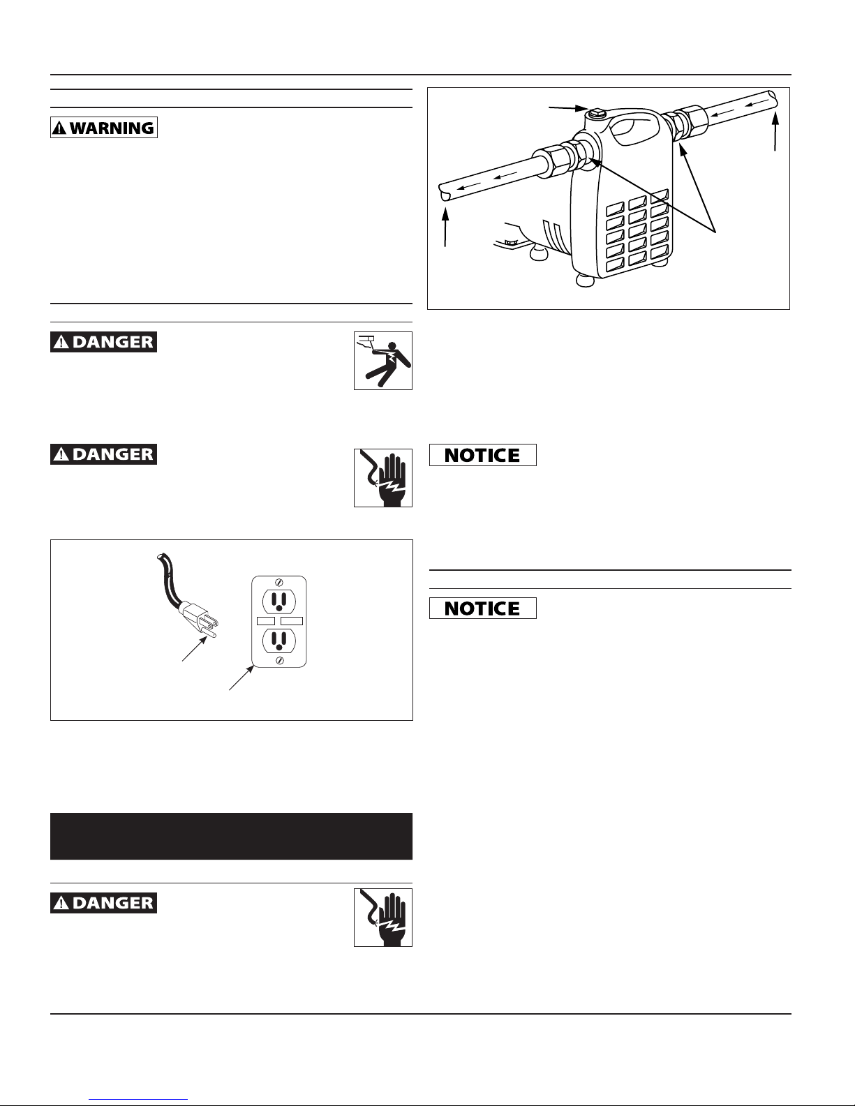
PRIME PLUG
INLET
OUTLET
Figure 2
HOSE
ADAPTERS
4. Figure 2 shows a typical installation. Threaded adapters are
furnished for attaching garden hose where conditions permit its
use. In no case should the pump be more than 15 feet above
or away from water source. Install a foot valve when suction lift
is over 10 feet or when suction line is over 10 feet long.
5. The inlet line may be galvanized pipe, plastic pipe, or reinforced
hose. Small leaks in suction line greatly reduce efficiency of
pump and may prevent priming.
Ordinary garden hose WILL collapse under
suction pressure and SHOULD NOT be used for
the inlet line, except in pressure boosting applications.
6. Use a strainer when pumping from a creek, pond, or source
where foreign objects may be sucked into the pump. The
strainer should prevent solids from entering the inlet line.
7. A regular garden hose may be used as a discharge line.
RESET
TEST
GROUNDING BLADE
Figure 1
GFCI RECEPTACLE
2. This pump operates on 115V, 60 Hz AC, single phase or 115V
DC.
3. Use an extension cord only if necessary. Follow the Extension
Cord Length Table for proper gage of 3-wire, grounding type
extension cord.
Extension Cord Length Table
Wire Size #18 #16 #14 #12
Length 25 ft 50 ft 100 ft 150 ft
Risk of fatal electrical shock. NEVER cut off the round
grounding prong. Cutting the cord or plug WILL void the
warranty and make the pump inoperable.
OPERATION
Pump must be filled with water before
operation. Running the pump dry WILL cause
damage to the shaft seal.
1. This unit is not waterproof or weatherproof and is not
intended to be used in showers, saunas, or other potentially
wet locations. The motor is designed to be used in a clean,
dry location with access to adequate cooling air. Ambient
temperatures around the motor should not exceed 104˚F (40˚C).
2. Remove priming plug and fill with water. Replace plug (plumbers
seal tape should be used on priming plug to prevent air leaks).
3. Plug power cord into GFCI protected electrical outlet. The
pump will prime in a few minutes depending on suction line
length. Use of foot valve on suction line is recommended.
4. In the case of pressure boosting, turn water on before starting
pump. This force primes the pump. Then, plug power cord into
GFCI protected electrical outlet.
5. Unplug cord to turn unit off.
www.waynepumps.com
2
Page 3

MAINTENANCE
Let pump cool for at least 20 minutes before
attempting to service. Motor MAY be extremely
hot. Personal injury MAY result.
1. Pump should be checked periodically for proper operation.
ALWAYS disconnect the electrical supply before
attempting to operate, service, or perform any
maintenance. If the power source is out of sight, lock and tag in the open
(off) position to prevent unexpected power application. Failure to do so
WILL result in fatal electrical shock. Only qualified electricians SHOULD
repair this unit. Improper repair WILL result in fatal electrical shock.
BRUSH REPLACEMENT
Brushes for this pump SHOULD be inspected
after 100 hours of operation.
Pumps with excess of 100 hours of operation may stop operating
or fail to start. This could be due to worn brushes or carbon buildup. The brushes should be removed and carbon removed. Worn
brushes are not covered under warranty. Replacement brushes may
be available from WAYNE Pumps. Call 1-800-237-0987 to order.
1) Disconnect electrical cord from power supply.
2) Remove brush caps with screwdriver.
3) Remove old brush assembly.
4) Replace brushes, make sure springs do not pinch during
assembly. Align/center tabs on the back of the brush spring
with the flats on the brush hlder. REF. fig3.
5) Replace brush caps.
For other problems, consult troubleshooting chart.
PC4
NOTES
__________________________________________________________
__________________________________________________________
__________________________________________________________
__________________________________________________________
__________________________________________________________
__________________________________________________________
__________________________________________________________
__________________________________________________________
__________________________________________________________
__________________________________________________________
__________________________________________________________
__________________________________________________________
__________________________________________________________
__________________________________________________________
__________________________________________________________
__________________________________________________________
__________________________________________________________
__________________________________________________________
__________________________________________________________
__________________________________________________________
__________________________________________________________
__________________________________________________________
www.waynepumps.com
3
Page 4
Operating Instructions and Parts Manual
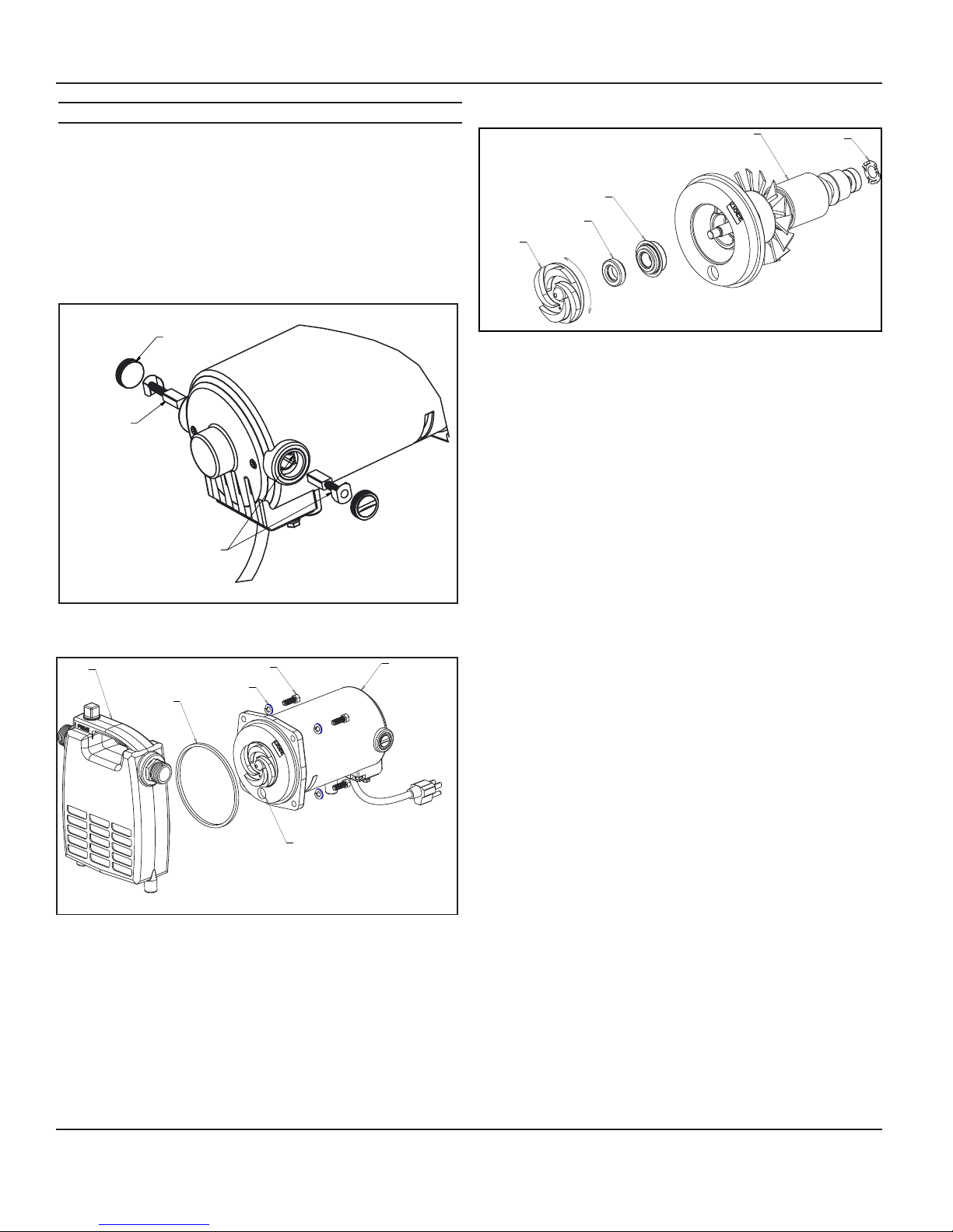
SERVICE PART REPLACEMENT
1. Make sure the pump is unplugged and cooled down before
disassembling the pump.
2. Release any pressure from the pump then disconnect any
hoses or plumbing, and drain the product.
3. Remove brush holder caps and brushes (make note of which
side of the pump the brush was in also the orientation of the
brush as you will want to put them back the same way they
came out.) Ref fig.3. Remove the (4) ¼-20 screws and lock
washers holding the volute to the motor housing. Ref fig.4
IMPELLER
HEAD SEAL
CERAMIC SEAL
LOOSE
ROTOR ASSEMBLY
THRUST WASHER
BRUSH HOLDER CAP
BRUSH
ALIGN TABS ON BRUSH
WITH FLATS ON BRUSH HOLDER
Figure 3
VOLUTE
GASKET
Figure 4
1/4-20 SCREW
WASHER
PRIMING FEATURE
MOTOR HOUSING
Figure 5
TIGHT
7. Holding the rotor assembly with one hand unscrew the impeller
from the rotor shaft. (Do not use a vise or other such device to
hold the rotor as it may damage the rotor.)
8. Remove both parts of the seal assembly from the back head
and impeller.
9. Push the new head seal (part with the blue metal housing) over
the rotor shaft and into the back head making sure the flange
on the seal seats against the back head and making sure the
black carbon side of the seal is facing away from the back head
towards the impeller.
10. Push the ceramic seal into the impeller pocket making sure the
white ceramic surface faces away from the back of the impeller.
11. Holding the rotor with one hand thread the new impeller onto
the rotor shaft making sure it is tight on the shaft and the white
face of the ceramic seal contacts the black carbon face of the
head seal.
12. Make sure the thrust washer is in the bearing pocket in the
back of the motor housing and guide the rotor assembly back
into the motor housing. Make sure the priming feature on the
back head is on the bottom of the pump, the pump won’t
prime properly if this isn’t in the correct location.
13. Put the new gasket on the motor housing then reattach the
volute to the motor housing using the four ¼-20 screws and
lock washers. Torque the screws to 75 in. lbs.
14. Replace the brushes and caps, make sure to put them back
in the same way they came out. Make sure the springs do not
pinch during assembly and align/center the tabs on the back of
the brush spring with the flats on the brush holder. Ref. fig.3
15. Test thoroughly and check for leaks before use.
4. Remove the volute.
5. Remove the gasket and discard.
6. Remove the rotor assembly from the motor housing. There is
a thrust washer in the bearing pocket at the back of the motor
housing, if the thrust washer falls out make sure it is put back
into the pocket before reassembling. Ref fig.5
www.waynepumps.com
4
Page 5

PC4
TROUBLESHOOTING CHART
Symptom Possible Cause(s) Corrective Action
Pump will not start or run 1. Blown fuse 1. If blown, replace with proper sized fuse or reset
2. Low line voltage 2. Contact an electrician
3. Worn brushes 3. Replace brushes
4. Impeller blocked 4. Remove blockage
5. Defective motor 5. Replace pump
Pump will not prime or retain prime after
operating
Flow rate is too low 1. Piping or hose is fouled or damaged 1. Clean or replace
Seal leaks 1. Worn seal 1. Replace seal
Thermal Protector Tripping 1. Damage or misalignment causing rotating
1. Air leak in suction line 1. Repair or replace suction line (use plumbers
2. Impeller blocked 2. Remove blockage
3. Worn seal 3. Replace seal
4. Suction lift too high 4. Lower pump
5. Hose kinked or looped 5. Straighten hose
6. Fittings not tight 6. Tighten fittings
7. Suction hose out of water 7. Submerge suction hose end
8. Clogged inlet 8. Clean inlet
2. Low line voltage 2. Contact an electrician
2. Backhead damaged or cracked 2. Replace backhead
3. Pump head loose on motor 3. Insure proper assembly and no obstruction,
parts to bind
2. High surrounding temperature 2. Provide a shaded, well-ventilated area for pump
3. Low line voltage 3. Contact an electrician
4. Motor housing air-vents blocked 4. Remove air-vent blockage
breaker
tape to install garden hose adpater fittings and
priming plug onto pump body)
tighten bolts
1. Take to motor repair shop or locate and repair
mechanical binding
www.waynepumps.com
5
Page 6
Operating Instructions and Parts Manual
For Replacement Parts or Technical Assistance,
For Replacement Parts or Technical Assistance,
call 1-800-237-0987
call 1-800-237-0987
Please provide following information:
Please provide following information:
- Model number
- Model number
- Serial number (if any)
- Serial number (if any)
- Part description and number as shown in parts list
- Part description and number as shown in parts list
2
Address parts correspondence to:
Address parts correspondence to:
Wayne Water Systems
Wayne Water Systems
101 Production Drive
101 Production Drive
Harrison, OH 45030 U.S.A.
Harrison, OH 45030 U.S.A.
1
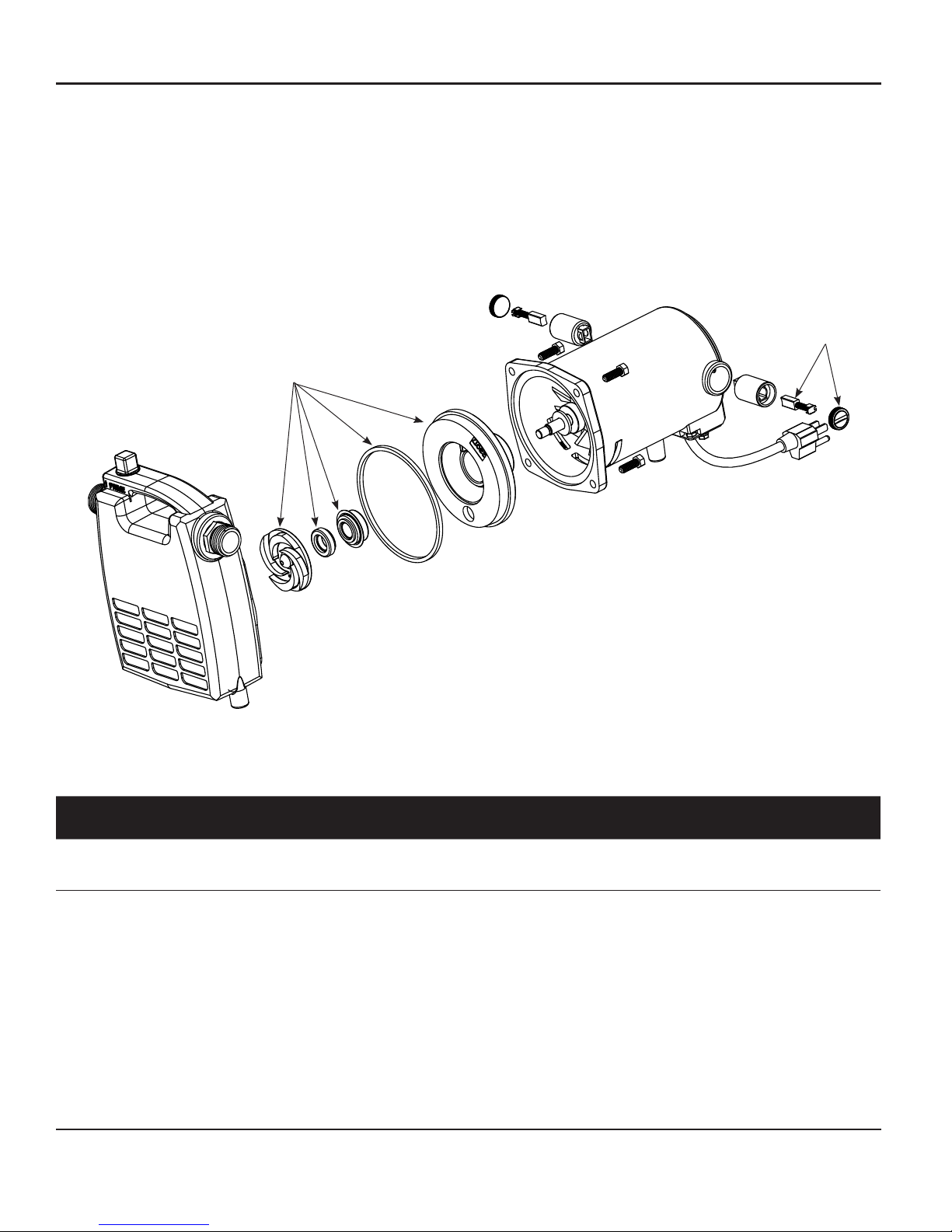
REPLACEMENT PARTS LIST
Ref.
No. Description Part Number Qty.
1
2
Note: Replacement parts are available in kit form only
www.waynepumps.com
Brush kit 62015-WYN1 1
Impeller and seal kit 56671-WYN1 1
6
6
Page 7

PC4
Limited Warranty
For one year from the date of purchase, WAYNE Water Systems (“WAYNE”) will repair or replace, at its option, for the original purchaser any part or
parts of its Sump Pumps or Water Pumps (“Product”) found upon examination by WAYNE to be defective in materials or workmanship. Please call
WAYNE (800-237-0987) for instructions or see your dealer. Be prepared to provide the model number when exercising this warranty. All transportation
charges on Products or parts submitted for repair or replacement must be paid by purchaser.
This Limited Warranty does not cover Products which have been damaged as a result of accident, abuse, misuse, neglect, improper installation,
improper maintenance, or failure to operate in accordance with WAYNE’s written instructions.
THERE IS NO OTHER EXPRESS WARRANTY. IMPLIED WARRANTIES, INCLUDING THOSE OF MERCHANTABILITY AND FITNESS
FOR A PARTICULAR PURPOSE, ARE LIMITED TO ONE YEAR FROM THE DATE OF PURCHASE. THIS IS THE EXCLUSIVE REMEDY
AND ANY LIABILITY FOR ANY AND ALL INDIRECT OR CONSEQUENTIAL DAMAGES OR EXPENSES WHATSOEVER IS EXCLUDED.
Some states do not allow limitations on how long an implied warranty lasts, or do not allow the exclusions or limitations of incidental or consequential
damages, so the above limitations might not apply to you. This limited warranty gives you specific legal rights, and you may also have other legal rights
which vary from state to state.
In no event, whether as a result of breach of contract warranty, tort (including negligence) or otherwise, shall WAYNE or its suppliers be liable for any
special, consequential, incidental or penal damages including, but not limited to loss of profit or revenues, loss of use of the products or any associated
equipment, damage to associated equipment, cost of capital, cost of substitute products, facilities, services or replacement power, downtime costs, or
claims of buyer’s customers for such damages.
You MUST retain your purchase receipt along with this form. In the event you need to exercise a warranty claim, you MUST send a copy of the
purchase receipt along with the material or correspondence. Please call WAYNE (800-237-0987) for return authorization and instructions.
DO NOT MAIL THIS FORM TO WAYNE. Use this form only to maintain your records.
MODEL NO. _____________________ SERIAL NO. ________________________ INSTALLATION DATE _____________________
ATTACH YOUR RECEIPT HERE
www.waynepumps.com
7
Page 8

Operating Instructions and Parts Manual
NOTES
www.waynepumps.com
8
Page 9

Bomba Portátil de Servicio con
Sistema de Cebado Automático
MANUAL DE INSTRUCCIONES DE FUNCIONAMIENTO Y
EZAS DE REPUESTOI
LEA, ENTIENDA Y SIGA TODAS LAS INSTRUCCIONES DE ESTE MANUAL. NO LO DESECHE. .
LEA, ENTIENDA Y SIGA TODAS LAS INSTRUCCIONES DE ESTE MANUAL. NO LO DESECHE. .
No seguir estas instrucciones podría provocar daño a la unidad, lesiones graves o la muerte.
No seguir estas instrucciones podría provocar daño a la unidad, lesiones graves o la muerte.
Model #
PC4
DESCRIPCIÓN
Las bombas portátiles de servicio con sistema de cebado automático
están diseñadas para usarse como bombas de desagüe para vaciar
calentadores de agua, tanques para animales, etc. Igualmente, las
bombas se pueden usar de modo intermitente para lavar coches, limpiar
entradas de garajes, etc. El motor se enfría con aire y no está diseñado
para operar bajo agua.
NOTA: Este bomba no está diseñada para una instalación permanente o
para períodos de trabajo continuo largos y extendidos.
PARA DESEMPACAR
Después de desempacar la bomba de uso general, inspecciónela
cuidadosamente para detectar cualquier daño que pueda haber ocurrido
durante el transporte. Verifique que no haya piezas sueltas, dañadas o
faltantes. Si necesita asistencia, llame a nuestro Departamento de Servicio
al Cliente al 1-800-237-0987.
MEDIDAS DE SEGURIDAD
Para ayudar a reconocer esta información, observe las siguientes señales/
clasificaciones de riesgos..
Peligro indica una situación inminentemente
peligrosa, la cual, si no se evita, TENDRÁ como
resultado la muerte o una lesión grave.
Advertencia indica una situación
potencialmente peligrosa, la cual, si no se evita,
PODRÍA resultar en la muerte o una lesión grave.
Ésto le indica que hay una situación que
PODRIA ocasionarle heridas no muy graves.
Aviso indica información importante, que si no
se respeta, puede causar daño al equipo.
Este es el símbolo de alerta de seguridad. Se utiliza para alertarle
sobre los peligros potenciales de lesiones corporales. Obedezca
todos los mensajes de seguridad que siguen a este símbolo para
evitar posibles daños.
NOTA: Información que requiere atención especial.
INFORMACIONES GENERALES DE SEGURIDAD
PROPOSICIÓN 65 DE CALIFORNIA
Este producto o su cable de corriente
contienen químicos, incluido plomo, que son
conocidos por el Estado de California como causantes de cáncer y
defectos de nacimiento u otros daños reproductivos. Use guantes al
manipular este producto y lávese las manos después de manipularlo.
SEGURIDAD GENERAL
NO sumerja el motor ni permita que el motor
esté expuesto al agua. CAUSARÁ lesiones
corporales y/o la muerte.
NO la use para bombear fluidos inflamables o explosivos,
como gasolina, aceite combustible, queroseno, etc. NO la
use en una atmósfera inflamable o explosiva. La bomba sólo
DEBE usarse para bombear agua limpia. CAUSARÁ lesiones corporales
y/o la muerte.
Peligro de electrocutamiento. Un electricista
calificado debe realizar TODO el cableado.
NO camine sobre áreas húmedas sino después de que
TODAS las fuentes de electricidad estén apagadas. El
desobedecer esta advertencia CAUSARÁ un choque
eléctrico mortal.
1. Lea todas las instrucciones antes de comenzar a usar la
bomba.
2. Desconecte el cordón eléctrico y libere toda la
presión del sistema antes de darle servicio a cualquier
componente.
3. Drene todos los líquidos del sistema antes de darle servicio.
Motor Monofásico - 115V, 60 Hz, 8,000 R.P.M. Caballos de Fuerza 1/2 CP
Motor Serie Wound (con escobillas) CA/CD Oricios de Entrada/Salida 19,1 mm (3/4 pulg) NPT
Propela Termoplástico Envoltura de la Bomba Hierro colado
Cubierta del Motor Hierro colado Eje del Motor Acero laminado en frío
Sellos del eje y la
Voluta
Temp. Máx. del
Fluído
RECORDATORIO: ¡Conserve su prueba de compra fechada para la garantía! Adjúntela a este manual o archívela para conservarla de forma segura.
RECORDATORIO: ¡Conserve su prueba de compra fechada para la garantía! Adjúntela a este manual o archívela para conservarla de forma segura.
© 2016,
© 2016,
WAYNE/Scott Fetzer Company.
WAYNE/Scott Fetzer Company.
Buna-N Cojinetes del Motor Lubricados de por Vida
49ºC (120ºF)
Para obtener información sobre piezas de repuesto, productos y servicio, visite www.waynepumps.com
Especicaciones
Sp-9
Sp-9
Rodamientos de bola
Page 10
Manual de instrucciones de funcionamiento y piezas de repuesto
INFORMACIONES GENERALES DE SEGURIDAD
(CONTINUACION)
Asegure la línea de descarga antes de dar
arranque a la bomba. Si no la asegura, ES
POSIBLE que se sacuda bruscamente y PODRÍAN causarse lesiones
personales y/o daños a la propiedad.
4. Periódicamente inspeccione la bomba y los componentes, chequée
si las mangueras están debilitadas o desgastadas. Cerciórese de
que todas las conecciones estén bien apretadas.
El motor de la bomba está equipado con un
circuito protector térmico de reconfiguración
automática y ES POSIBLE que se reactive repentinamente. La
desconexión del circuito protector indica un recalentamiento del motor
debido a que la bomba está funcionando con presión hidrostática
baja (restricción de descarga baja), voltaje excesivamente alto o bajo,
cableado inadecuado, temperatura excesiva del aire circundante,
ventilación inadecuada y/o motor o bomba defectuosos.
5. Cerciórese de que haya una forma de liberar la presión en caso de
que la línea de descarga se obstruya.
6. Proteja los cordones eléctricos contra objetos afilados, superficies
calientes, aceite y químicos. Evite que el cordón se enrolle y
reemplace los cordones dañados inmediatamente.
INSTALACIÓN
SIEMPRE desconecte la fuente de energía antes de intentar
operar o reparar la bomba, o darle mantenimiento. NUNCA
manipule la bomba con las manos húmedas o cuando se
encuentre sobre una superficie húmeda o mojada, ni dentro del agua.
OCURRIRÁ un choque eléctrico mortal.
1. Necesita usar un cortacircuito automático con conexión a tierra.
¡Peligro de morir electrocutado! Esta bomba tiene un conductor
para conexión a tierra y un enchufe para conexión a tierra. Debe
utilizar un tomacorrientes que cumpla con los códigos vigentes
nacionales (NEC en EE.UU.) y locales (Vea la Figura 1).
2. Esta bomba sólo se debe usar con circuitos de 115 voltios
(monofásicos), 60 Hz CA, ó 115 voltios CD.
RESET
TEST
Tabla de las Longitudes de los Cordones de Extensión
Tamaño del
alambre #18 #16 #14 #12
Longitud 8 m 15 m 31 m 45 m
Riesgo de choque eléctrico mortal. NUNCA corte la clavija
redonda de conexión a tierra. Si corta el cable o el enchufe, SE
ANULARÁ la garantía y hará que la bomba no funcione.
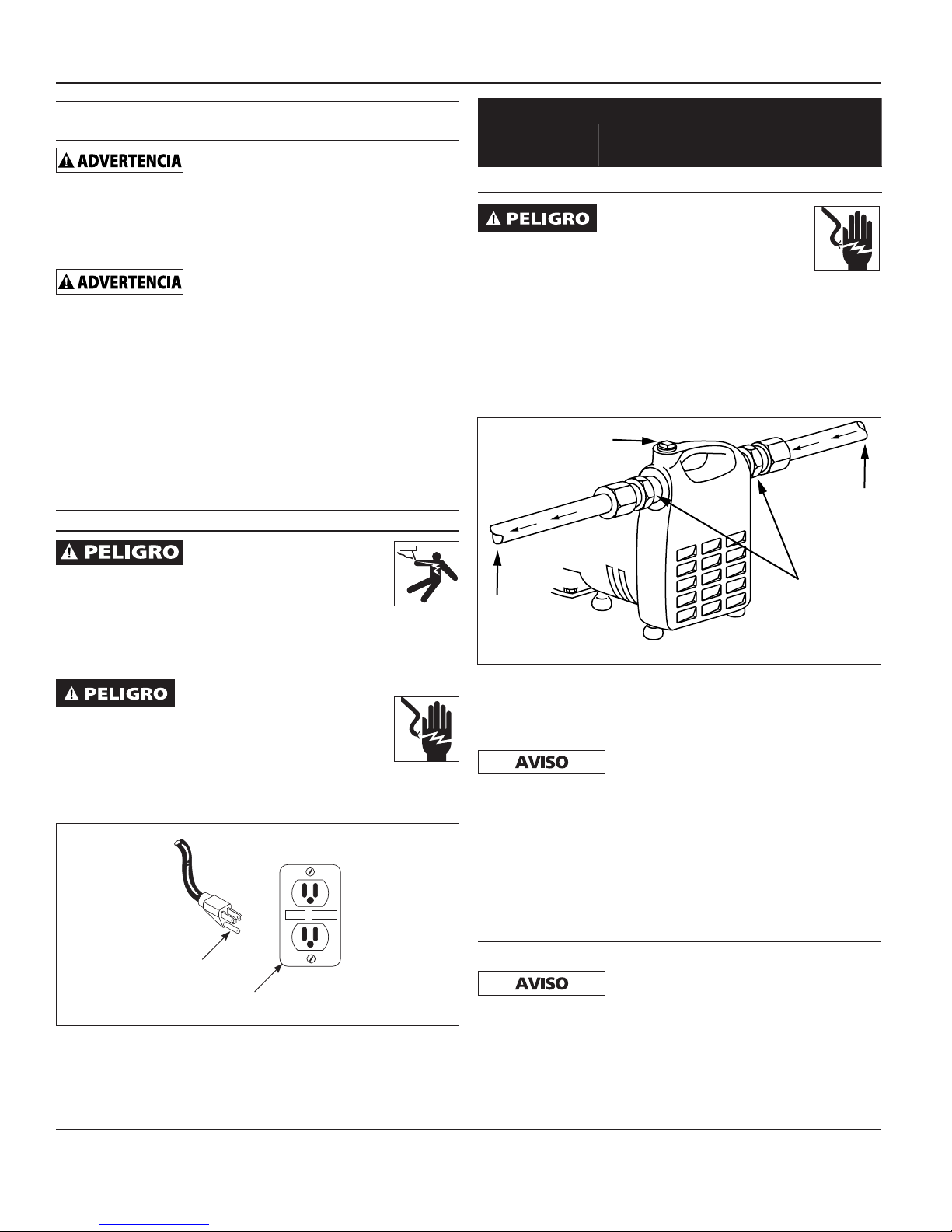
4. La Figura 2 le indica cómo instalar la bomba. Los adpatadores con
roscas se le suministran para que conecte mangueras para jardín
cuando las condiciones lo permitan. En ningún caso la bomba debe
colocarse a más de 4,5 m (15 pies) de distancia o de altura con
respecto a la entrada de agua. Instale una válvula de pie cuando la
altura de succión sea superior a los 3 m (10 pies) o cuando la línea
de succión tenga más de 3 m (10 pies) de largo.
TAPÓN DEL
SISTEMA DE
CEBADO
ENTRADA
SALIDA
Figura 2
ADAPTADORES
DE MANGUERA
5. La línea de entrada puede ser un tubo galvanizado o de plástico, o
una manguera reforzada. Las fugas pequeñas en la línea de succión
reducen en gran medida la eficiencia de la bomba y pueden impedir
el cebado.
Las mangueras de jardín normales
COLAPSARÁN con la presión de succión; por lo
tanto, NO DEBEN usarse para la línea de entrada, con excepción de los
sistemas para aumentar la presión.
6. Use un colador cuando vaya a bombear agua de un riachuelo,
charca o cualquier sitio donde pueda haber basura que podría
obstuir la bomba. El colador debe evitar la entrada de sólidos a la
línea de entrada de la bomba.
7. Puede usar una manguera común para jardines como línea de
descarga.
TERMINAL PARA
CONEXIÓN A TIERRA
Figura 1
TOMACORRIENTES GFCI
(CONECTADO A TIERRA)
3. Use un cordón de extensión sólo cuando sea necesario. Use
cordones de extensión, de tres alambres para conexión a tierra que
sean de la longitud y calibre indicados en la Tabla de cordones de
extensión.
www.waynepumps.com
FUNCIONAMIENTO
Debe llenar la bomba de agua antes de
encenderla. Hacer funcionar la bomba en seco
CAUSARÁ daños en el sello del eje.
1. Esta unidad no es a prueba de agua o a prueba de intemperie y no
está diseñada para usarse en duchas, saunas, ni ningún sitio donde
se pueda mojar. El motor está diseñado para usarse en sitios limpios
y secos donde tenga acceso a aire adecuado para enfriarlo. La
temperatura ambiental alrededor del motor no debe exceder 40˚C
(104˚F).
Sp-10
Page 11

PC4
2. Quítele el tapón al sistema de cebado y llénelo de agua. Vuelva a
colocar el tapón (se debe usar cinta de sellado de plomería en el
tapón de cebado para evitar fugas de aire).
3. Conecte el cordón eléctrico a un tomacorrientes con cortacircuito
automático con conexión a tierra. La bomba completará el proceso
de cebado en pocos minutos, dependiendo de la longitud de la
línea de succión. Le recomendamos que use una válvula de pie en
la línea de succión.
4. En caso de que la vaya a usar para aumentar la presión de agua,
abra la llave de agua antes de encender la bomba. La bomba
se cebará con la presión del agua. Después, conecte el cordón
eléctrico a un tomacorrientes a un tomacorrientes con cortacircuito
automático con conexión a tierra.
5. Desconecte el cordón para apagar la unidad.
MANTENIMIENTO
Debe esperar por lo menos 20 minutos para que
la bomba se enfrie antes de darle servicio. ES
POSIBLE que el motor esté muy caliente. ES POSIBLE causar lesiones
personales.
1. Debe chequear la boomba periódicamente para ver si está
funcionando adecuadamente.
SIEMPRE desconecte el suministro de corriente
antes de intentar operar, efectuar reparaciones
o realizar cualquier tipo de mantenimiento. Si la fuente de energía está
fuera de la vista, bloquéela y etiquétela en la posición abierta (off)
para evitar que se suministre corriente en forma inesperada. Dejar de
hacer esto CAUSARÁ un choque eléctrico mortal. Esta unidad DEBE
ser reparada únicamente por electricistas calificados. La reparación
incorrecta CAUSARÁ un choque eléctrico mortal.
PARA REEMPLAZAR LAS ESCOBILLAS
Las escobillas de esta bomba DEBEN
inspeccionarse después de 100 horas de
funcionamiento.
Después de 100 horas de funcionamiento la bomba podría dejar de
funcionar o no encender. Ésto podría ser debido al desgasto de las
escobillas o a la acumulación de carbón. Debe desmontarle las escobillas
y quitarle los residuos de carbón. Las escobillas no están cubiertas en
la garantía. Para ordenar escobillas de repuesto comuníquese con el
distribuidor de bombas WAYNE más cercano a su domicilio. En EUA
llame al 1-800-323-0620 para ordenarlas.
1.) Desconecte el cordón eléctrico del tomacorrientes.
2.) Use un desarmador para quitarle las tapas a las escobillas.
3.) Saque el ensamblaje de las escobillas usadas.
4.) Reemplace los cepillos, asegúrese de que los resortes no queden
mordidos durante el ensamblaje. Alinee/centre las langüetas detrás
del resorte del cepillo con las superficies planas del sujetador del
cepillo. Ref. Fig 3.
5.) Colóquele las tapas de las escobillas.
Si tiene otros problemas, consulte la guía de diagnóstico de averías
NOTAS
__________________________________________________________
__________________________________________________________
__________________________________________________________
__________________________________________________________
__________________________________________________________
__________________________________________________________
__________________________________________________________
__________________________________________________________
__________________________________________________________
__________________________________________________________
__________________________________________________________
__________________________________________________________
__________________________________________________________
__________________________________________________________
__________________________________________________________
__________________________________________________________
__________________________________________________________
__________________________________________________________
__________________________________________________________
__________________________________________________________
__________________________________________________________
__________________________________________________________
www.waynepumps.com
Sp-11Sp-11
Page 12
Operating Instructions and Parts Manual
REEMPLAZO DE PIEZAS DE REPUESTO
1. Asegúrese de que la bomba esté desconectada y fría antes de
desarmarla.
2. Libere toda la presión de la bomba y luego desconecte las
mangueras o tuberías, y drene el producto.
3. Retire las tapas de los soportes de las escobillas y las escobillas
(tome nota de qué lado de la bomba estaban las escobillas,
así como la orientación de las mismas, ya que las volverá a
colocar de la misma manera en que las quitó). Consulte la fig.
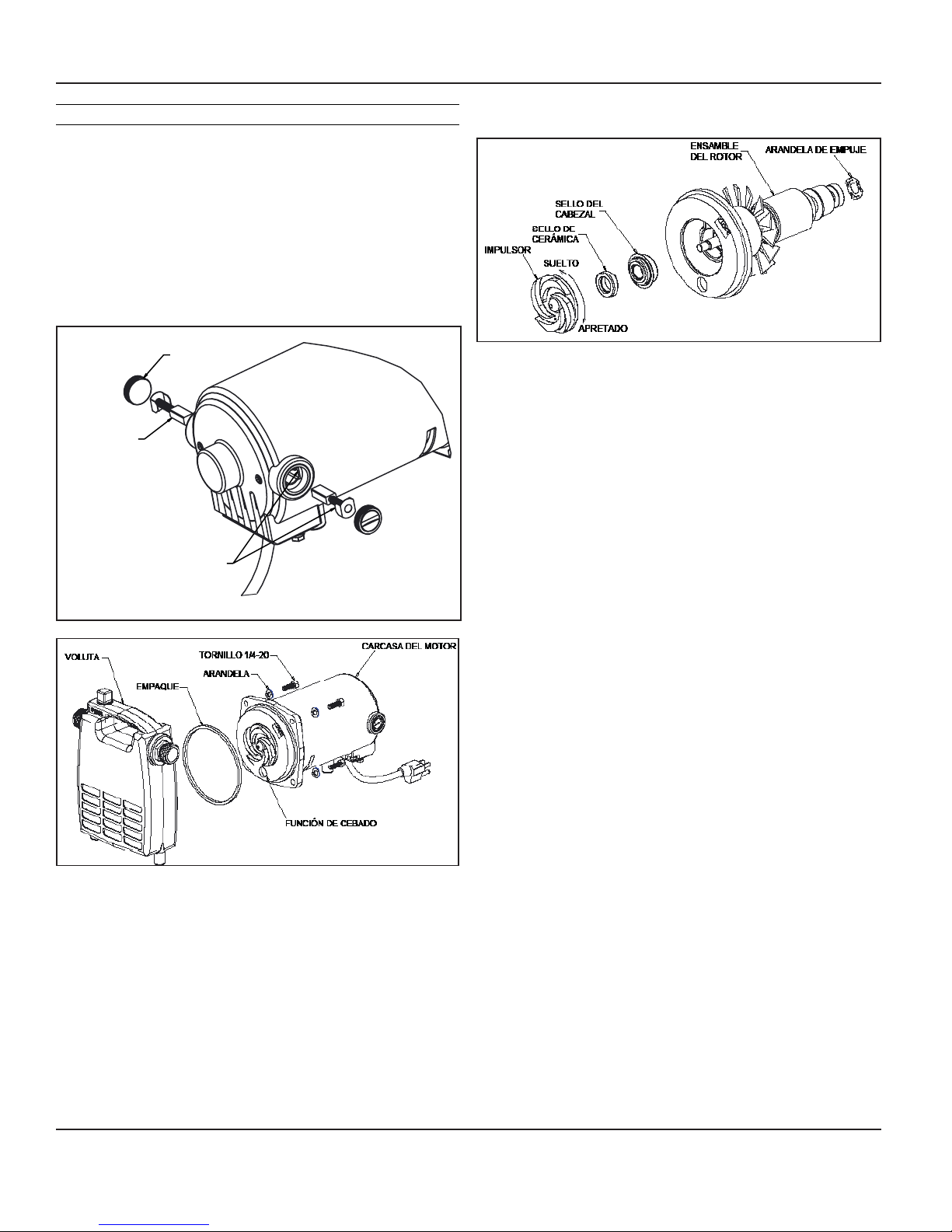
3. Quite los (4) tornillos ¼-20 y las arandelas de seguridad que
sostienen la voluta a la carcasa del motor. Consulte la fig. 4
TAPA DEL SOPORTE
DE LAS ESCOBILLAS
ESCOBILLAS
ALINEE LAS LENGÜETAS DE LAS
ESCOBILLAS CON LAS ÁREAS PLANAS
DEL SOPORTE DE LAS ESCOBILLAS
Figura 3
Figura 4
4. Quite la voluta.
5. Quite el empaque y deséchelo.
6. Retire el ensamble del rotor de la carcasa del motor. Hay una
arandela de empuje en la cavidad del rodamiento situada en
la parte posterior de la carcasa del motor, si la arandela de
empuje se cae, asegúrese de colocarla de nuevo en la cavidad
antes de volver a armar la bomba. Consulte la fig. 5
Figura 5
7. Sosteniendo el ensamble del rotor con una mano, desenrosque
el impulsor del eje del rotor. (No use un tornillo de banco u otro
dispositivo similar para sostener el rotor, pues puede dañarlo).
8. Quite ambas piezas del ensamble del sello del cabezal trasero y
del impulsor.
9. Empuje el nuevo sello del cabezal (parte con la caja de metal
azul) sobre el eje del rotor y hacia dentro del cabezal trasero,
asegurándose de que la brida del sello se asiente contra el
cabezal trasero y asegurándose de que el lado de carbón
negro del sello esté orientado lejos del cabezal trasero y hacia
el impulsor.
10. Empuje el sello de cerámica hacia dentro de la cavidad del
impulsor, asegurándose de que la superficie de cerámica
blanca esté orientada hacia la parte trasera del impulsor.
11. Sosteniendo el rotor con una mano, enrosque el nuevo
impulsor sobre el eje del rotor, asegurándose de que esté
apretado sobre el eje y la cara blanca del sello de cerámica esté
en contacto con la cara de carbón negro del sello del cabezal.
12. Asegúrese de que la arandela de empuje esté en la cavidad del
rodamiento situada en la parte trasera de la carcasa del motor y
guíe el ensamble del rotor de nuevo hacia dentro de la carcasa
del motor. Asegúrese de que la función de cebado del cabezal
trasero esté en la parte inferior de la bomba; la bomba no se
cebará correctamente si esto no está en el lugar correcto.
13. Coloque el nuevo empaque en la carcasa del motor, luego
vuelva a sujetar la voluta a la carcasa del motor usando los
cuatro tornillos ¼-20 y las arandelas de seguridad. Apriete los
tornillos a un torque de 75 pulg. lb.
14. Vuelva a colocar las escobillas y tapas, asegúrese de colocarlas
de nuevo de la misma manera en que las quitó. Asegúrese
de que los resortes no pellizquen algo durante el ensamble y
alinee/centre las lengüetas en la parte trasera del resorte de las
escobillas con las áreas planas en el soporte de las escobillas.
Consulte la fig. 3
15. Pruebe por completo y verifique que no haya fugas antes de
usarla.
www.waynepumps.com
Sp-12
Page 13

TABLA DE IDENTIFICACIÓN DE PROBLEMAS
Síntoma Causa(s) Posible(s) Medida Correctiva
La bomba no se
enciende ni funciona
La bomba no se ceba o
lo pierde después de
funcionar
El flujo es muy bajo 1. Las tuberías o mangueras están obstruídas
Los sellos tienen fugas 1. El sello está desgastado 1. Reemplace el sello
Desconexión del circuito protector térmico 1. Daño o desalineación que hace que las
1. Un fusible quemado 1. Si está quemado, reemplácelo con un fusible
adecuado o active el cortacircuito
2. El voltaje es muy bajo 2. Póngase en contacto con un electricista
3. Las escobillas están desgastadas 3. Reemplace las escobillas
4. La propela está obstruída 4. Quítele lo que la está obstruyendo
5. El motor está dañado 5. Reemplace la bomba
1. Hay fuga de aire en la línea de succión 1. Repare o reemplace la línea de succión (use
cinta de plomería para instalar en el cuerpo de la
bomba los adaptadores de la manguera de jardín
y el tapón de cebado)
2. La propela está obstruída 2. Quítele lo que la está obstruyendo
3. El sello está desgastado 3. Reemplace el sello
4. El nivel de succión es muy alto 4. Coloque la bomba en un sitio más bajo
5. La manguera está enrollada 5. Enderece la manguera
6. Las conexiones están flojas 6. Apriete las conexiones
7. La manguera de succión no tiene agua 7. Sumerja el extremo de la manguera de succión
8. El orificio de entrada está obstruído 8. Limpie el orificio de la entrada
o dañadas
2. El voltaje es muy bajo 2. Póngase en contacto con un electricista
2. Cabezal dañado o partido 2. Cambie el cabezal
3. La bomba está mal conectada al motor 3. Cerciórese de que esté bien conectada y que no
piezas giratorias se atasquen
2. Temperatura circundante alta 2. Proporcione un área con sombra y bien ventilada
3. Bajo voltaje de la línea 3. Póngase en contacto con un electricista
4. Agujeros de ventilación de la caja del motor
bloqueados
1. Límpielas o reemplácelas
esté obstruída, apriete los pernos
1. Lleve el motor al taller de reparaciones o ubique
y repare el atascamiento mecánico
para la bomba
4. Quite el bloqueo de los agujeros de ventilación
Sp-13
Sp-13
www.waynepumps.com
Page 14

Manual de instrucciones de funcionamiento y piezas de repuesto
Para Ordenar Repuestos o Asistencia Técnica, Sírvase Llamar al
Para Ordenar Repuestos o Asistencia Técnica, Sírvase Llamar al
Distribuidor Más Cercano a Su Domicilio
Distribuidor Más Cercano a Su Domicilio
Sirvase darnos la siguiente información: Dirija toda la correspondencia a:
- Número del modelo Wayne Water Systems
- Código impreso 101 Production Drive
- Descripción y número del repuesto según la lista de repuestos Harrison, OH 45030 U.S.A.
2
1
LISTA DE PARTES DE REPARACIÓN
No. de
Ref. Descripción Número de Parte Ctd.
1
2
Nota: Los repuestos sólo están disponibles en juegos
www.waynepumps.com
Juego de escobillas 62015-WYN1 1
Juego de propela y sellos 56671-WYN1 1
Sp-14
Sp-14
Page 15

NOTES
PC4
www.waynepumps.com
Sp-15
Page 16

PC4
Manual de instrucciones de funcionamiento y piezas de repuesto
Garantie Limitée
Durante un año a partir de la fecha de compra, WAYNE Water Systems (“WAYNE”) reparará o reemplazará, según lo consideren
adecuadon, cualquier pieza de esta bomba para sumideros (“Producto”) que el comprador original envie a reparación y los empleados o
representantes autorizados de WAYNE determinen que están defectuosos debido a problemas de materiales o manufactura. Para recibir
información sobre los pasos a seguir, comuníquese directamente con la compañía WAYNE (800-237-0987, sólo desde EUA), o con el
distribuidor autorizado más cercano a su domicilio. En el momento de reclamar sus derechos bajo esta garantía deberá suministrarnos
el número del modelo. Todos los gastos de flete serán la responsabilidad del comprador.
Esta garantía limitada no cubre los daños debido a accidentes, abusos, uso inadecuado, negligencia, instalación inadecuada,
mantenimiento inadecuado, o funcionamiento sin seguir las instrucciones suministradas por escrito por la compañía WAYNE.
NO HAY NINGUNA OTRA GARANTIA EXPRESA O IMPLISITA. INCLUYENDO AQUELLAS SOBRE VENTA O USOS
ESPECIFICOS, Y LAS GARANTIAS ESTAN LIMITADAS A UN AÑO A PARTIR DE LA FECHA DE COMPRA. ESTA ES LA UNICA
GARANTIA Y CUALQUIER PERDIDA O RESPONSABILIDAD CIVIL, SEA DIRECTA O INDIRECTA COMO CONSECUENCIA DE
DAÑOS SON EXCLUIDAS.
Algunos estados no permiten límites en la duración de las garantías, o no permiten que se limiten o excluyan casos por daños por
accidentes o consecuentes, en dichos casos los límites arriba enumerados tal vez no apliquen para Ud. Esta garantía limitada le otorga
a Ud. ciertos derechos que pueden variar de un estado a otro.
Bajo ninguna circunstyancia, aunque sea debido al incumplimiento del contrato de garantía, culpabilidad (incluyendo negligencia) u otras
causas,la compañía WAYNE o ninguno de sus surtidores serán responsables legalmente por ningún fallo legal en su contra, incluyendo,
pero no limitado apérdida de ganancias, pérdidas del uso del producto o piezas asociadas con el equipo, pérdidas de capital, gastos
para reemplazar los productos dañados, pérdidas por cierre de fábrica, servicios o pérdida de electricidad, o demandas persentadas por
los clientes del comprador por dichos daños.
Ud. DEBE conservar el recibo como prueba de compra junto con esta garantía. En caso de que necesite presentar un reclamo de
sus derechos bajo esta garantía, Ud DEBERA enviar una copia del recibo de la tienda junto con el producto o correspondencia.
Comuníquese con la compañía WAYNE (800-237-0987, sólo desde EUA) para recibir autorización e instrucciones de como enviar la
mercancía.
NO ENVIE ESTA GARANTIA A WAYNE. Use este documento sólo para mantener sus records.
NO. DEL MODELO _____________________ NO. DE SERIE ________________________ FECHA DE INSTALACION __________________
ANEXE SU RECIBO AQUI
www.waynepumps.com
www.waynepumps.com
Sp-16Sp-16Sp-16
 Loading...