

Page 1
Operating Instructions and Parts Manual JSU50
Please read and save these instructions. Read carefully before attempting to assemble, install, operate or maintain the product described.
Protect yourself and others by observing all safety information. Failure to comply with instructions could result in personal injury and/or
property damage! Retain instructions for future reference.
Jet Pump
Description
These pumps are single stage domestic
water pumps designed for pumping
potable water. Shallow well pumps are
designed for applications where the
water level is less than 25 feet below the
pump. Flammable liquids such as gasoline,
chemicals, or corrosive liquids should never
be used with these pumps.
Unpacking
Inspect this unit before it is used.
Occasionally, products are damaged
during shipment. If the pump or
components are damaged, call
Customer Service at 1-800-237-0987.
Safety Guidelines
This manual contains information
that is very important to know
and understand. This information
is provided for SAFETY and to
PREVENT EQUIPMENT PROBLEMS. To
help recognize this information, observe
the following symbols.
Danger indicates an
imminently
hazardous situation which, if NOT
avoided, WILL result in death or serious
injury.
Warning indicates a
potentially
hazardous situation which, if NOT
avoided, COULD result in death or serious
injury.
Caution indicates a
potentially
hazardous situation which, if NOT
avoided, MAY result in minor or moderate
injury.
Notice indicates
important
information, that if NOT followed, MAY
cause damage to equipment.
NOTE: Information that requires special
attention.
General Safety
Information
CALIFORNIA PROPOSITION 65
This product
contains chemicals,
including lead, known to the State of
California to cause birth defects and
other reproductive harm. Wash hands
after handling.
1. Read these rules and instructions
carefully. Failure to follow these
instructions COULD cause serious
bodily injury and/or property
damage.
This pump is non-
submersible.
Install indoors only
or in a pump house.
Risk of electrical shock.
Pump only clear water. Do
NOT pump flammable or
explosive fluids such as
gasoline, fuel oil, kerosene, etc. Do NOT
use in a flammable and/or explosive
atmosphere. Personal injury and/or
property damage WILL result.
This pump is
not designed
to handle salt water, brine, laundry
discharge, or any other application
which may contain caustic chemicals
and/or foreign materials. Pump
damage COULD occur if used in these
applications and WILL void warranty.
All wiring must be performed
by a qualified electrician. The
pump must be installed in
compliance with the National Electrical
Code and all local codes.
2. Connect this pump to a grounded
circuit equipped with a ground fault
interrupter device (GFCI).
3. Before installing this product,
have the electrical circuit checked
by an electrician to ensure proper
grounding.
Risk of electric shock! Pump
must be disconnected
from power source before
installing or servicing.
4. Be sure the water source and piping
is clear of sand, dirt, and scale.
Debris will clog pump and void
warranty.
5. Protect pump and piping from
freezing. Failure to protect from
freezing COULD cause severe
damage and will void the warranty.
6. Follow priming instructions. Do NOT
run pump dry.
Installation
Protect pump from the elements by
installing in a basement, garage, tool
shed, or pump house. Install the pump
so the centerline of the pump is as close
as possible to the water level. Keep
installation area clear to provide access
for service and maintenance. Protect
the pump against flooding and excess
moisture.
REMINDER: Keep your dated proof of purchase for warranty purposes!
Attach it to this manual or file it for safekeeping.
For parts, product & service information
visit www.waynepumps.com
311405-001 6/11© 2011, WAYNE/Scott Fetzer Company.
Page 2
Operating Instructions and Parts Manual JSU50
Installation (Continued)
Make sure the pump has adequate
ventilation. The surrounding
temperature should not exceed 100˚F
(38˚C) or nuisance tripping of thermal
overload protector on the motor may
occur.
PUMP PIPING INSTALLATION
Use new pipe for best results. Iron,
copper or PVC pipe may be used.
To avoid strain on the pump when
using iron or copper pipe, provide
independent supports for both suction
and discharge piping near the pump.
Minimize use of elbows and fittings
to reduce friction loss. Refer to the
friction loss chart (page 5) for specific
information. Increase diameter of
suction or discharge piping if length is
over 50 feet.
TO
WATER
LINE
TO
WELL
OR
CISTERN
Figure 1 - Pipe Installation
SUCTION PIPING
Install foot valve
or strainer screen
over intake of suction piping.
Never use pipe smaller than 1-1/4”
diameter for suction piping. Keep
suction pipe free of air leaks. For
horizontal runs, lay pipe from the water
source so the upward slope is at least
1/2" per foot. This eliminates trapped
air. The threaded inlet of the pump is
1-1/4" NPT.
Do not install
suction piping near
swimming areas.
www.waynepumps.com
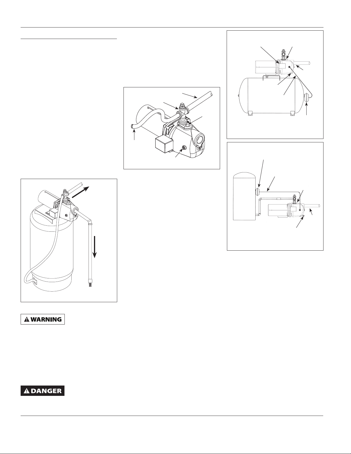
DISCHARGE PIPING (FIGURE 2)
Install a 3/4” pipe cross (sold separately)
in the pump discharge. Plug top of
pipe cross with 3/4” NPT pipe plug (sold
separately). Insert tank tubing into side
opening of pipe cross. Insert pipe into
remaining side opening for connection
to home water supply line.
PIPING TO HOME
WATER SYSTEM
PIPE CROSS
PRIME
PLUG
TANK
TUBING
Figure 2
AIR VOLUME CONTROL
CONNECTION
CONNECTION TO WATER TANK
CONVENTIONAL TANK (SEE FIGURES 3
& 4)
A conventional water tank stores
water and pressurized air in the same
compartment. When full, the tank
contains approximately 2/3 water and
1/3 compressed air. This type of tank
requires an air volume control, which
automatically replaces air lost due to
leak or absorption into the water.
1. Shut off power to pump. Disconnect
and lock out power source.
2. Drain the tank. Opening faucet
nearest tank is recommended.
3. Insure tank is secured to the floor or
base.
4. Bolt pump to the floor or the
mounting bracket on tank.
5. Install air volume control on tank.
6. Connect the tube from the air
volume control to the front 1/8"
NPT opening on the side of the
pump. Connections must be tight.
Leaks will cause the pump not to
prime and/or the tank to become
waterlogged.
7. Install a valve and an isolator hose
between the tank and the house
plumbing. This will reduce the noise
level of the pump system and aid in
servicing.
8. Provide a hose bib (faucet) at the
lowest point in the system to drain
the system for service or storage.
PRESSURE
SWITCH
DRAIN FITTING
AIR VOLUME
CONTROL
TUBING
Figure 3 - Shallow Well Pump with
Conventional Horizontal Tank
AIR VOLUME
CONTROL
AIR VOLUME
CONTROL TUBING
Figure 4 - Shallow Well Pump with
Conventional Vertical Tank
PRIME PLUG
INLET
AIR VOLUME
CONTROL
PRIME
PLUG
INLET
DRAIN
FITTING
9. Slope horizontal lines up toward
pump a minimum of 1/4" per foot.
This will prevent trapping air in the
lines.
PRE-CHARGED TANK (SEE FIGURE 5)
A pre-charged water tank stores air
and water in separate compartments,
separated by a flexible bladder. The
barrier prevents the air from being
absorbed into the water. The bladder
design also allows the water to be
acted on by higher pressures for longer
periods than a conventional tank.
Pre-charged tanks have roughly twice
the usable capacity of a conventional
tank with equal volume. The air
pressure in a pre-charged tank must be
checked periodically to insure it is at an
acceptable level (See Maintenance).
1. Shut off power to pump. Disconnect
and lock out power source.
2. Drain the tank. Open faucet nearest
the tank.
2
Page 3
Operating Instructions & Parts Manual
JSU50
Installation (Continued)
PRESSURE
SWITCH
Air VAlVe
(28-30 PSi)
1/2 HP, 3/4 HP, & 1 HP
Figure 5 - Shallow Well Pump
Precharged Tank
3. Insure tank is secured to the floor or
base.
4. Bolt pump to the floor or the
mounting bracket on tank.
5. Set air pressure in tank to desired
level. An air valve is located on
the side and will accept a standard
fitting from a bicycle pump or air
line.
6. Install a valve and an isolator hose
between the tank and the house
plumbing. This will reduce the noise
level of the pump system and aid in
servicing.
7. Provide a hose bib (faucet) at the
lowest point in the system to drain
the system for service or storage.
8. Slope horizontal lines up toward
pump a minimum of 1/4" per foot.
This will prevent trapping air in the
lines.
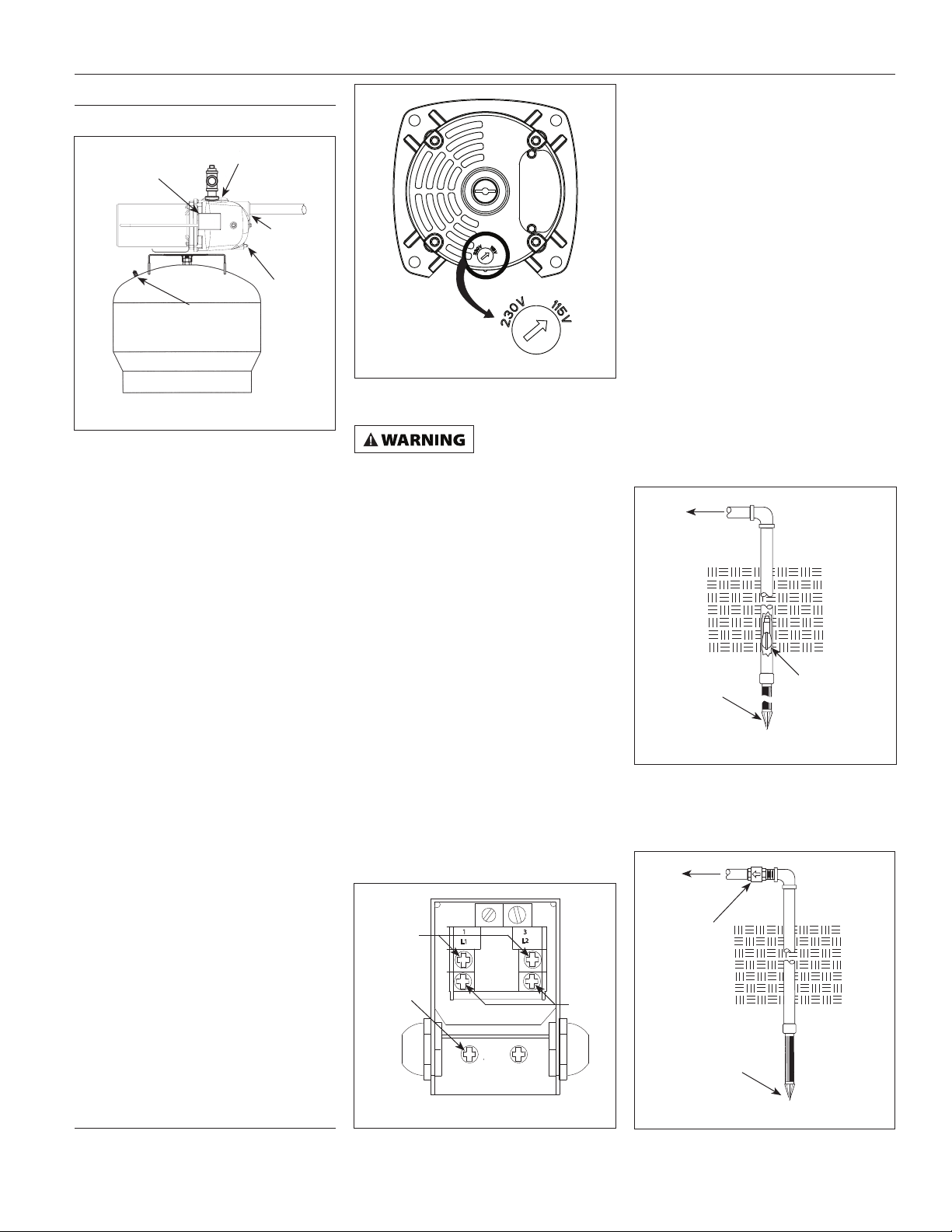
ELECTRICAL CONNECTIONS
The voltage of power supply must
match the voltage of the pump. Above
ground well pumps covered in this
manual have dual voltage motors
preset at the factory to 115 volts. The
motors can be converted to 230 volts
by turning the voltage selector to the
desired voltage (See Figure 6). Use a
needle nose pliers to pull the selector
out approximately 1/4”, rotate and then
reinsert in correct position.
Connect the pump to a separate
electrical circuit with a dedicated
circuit breaker. Refer to the electrical
specifications in the Wiring Chart
PRIME PLUG
INLET
DRAIN
FITTING
Figure 6 - Voltage Selector
(on page 5) for recommended circuit
breaker and wire size.
Install and maintain
wiring for this
pump in accordance with the National
Electrical Code and all applicable local
codes.
The motor must be grounded by
connecting a copper conductor to the
grounding screw provided within the
wiring compartment in the pressure
switch.
The field wiring compartment for the
jet pump is inside the pressure switch
housing. There is only one proper
ground screw on the unit. The screw is
located under the pressure switch cover,
painted green and is identified as GRD.
The ground connection must be made
to this terminal (Figure 7).
Refer to the wiring diagram located
under the cover of the pressure switch
(Figure 7).
To attach AC power to the pressure
switch, first ensure power has been
disconnected to the circuit. Loosen
the screw holding the cover onto the
pressure switch and remove the cover.
LINE
ATTACH
GROUND
WIRE
HERE
Figure 7 - Electrical Connections
1
L1
3
L2
MOTOR
Loosen unused ground screw and
attach the exposed end of the ground
wire between the screw head and the
pressure switch body, then tighten.
Loosen the top two screws on the
pressure switch and retighten with the
AC power leads captured under the
screw heads. Reattach the pressure
switch cover and tighten the screw.
CONNECTION TO WATER SOURCE
DRIVEN WELL
1. Drive the point several feet below
the water table.
NOTE: A packer-type foot valve can
be installed in the well (Figure 8). This
type of foot valve allows the well pipe
to be filled with water when priming
and makes the inlet pipe much easier to
test for leaks. Follow the manufacturer’s
instructions when installing the packertype foot valve.
TO PUMP
PACKER TYPE
DRIVE POINT
Figure 8 - Packer-Type Foot Valve
FOOT VALVE
As an alternative, an in-line check valve
can be used with a driven well (Figure
9).
TO PUMP
INLINE
CHECK
VALVE
DRIVE POINT
Figure 9 - In-Line Check Valve
www.waynepumps.com
3
Page 4
WARNING
Operating Instructions and Parts Manual
JSU50
Installation (Continued)
Do NOT use both
a check valve and
foot valve in your system. This COULD
significantly reduce the performance of
the pump.
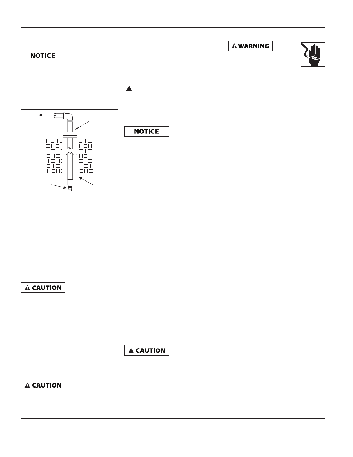
DRILLED WELL
1. Install a foot valve on the first
section of pipe (Figure 10).
TO PUMP
FOOT
VALVE
Figure 10 - Well Seal
2. Lower the pipe into the well.
3. Add pipe until the foot valve is 10
feet below the lowest anticipated
water level.
Leaking joints or couplings will allow
air to leak into the pipe and cause poor
pump operation. Make sure to use pipe
joint compound or plumbers seal tape
on all pipe connections.
Locate foot valve at
least 2 feet from
the bottom of the well so sand or
sediment is NOT drawn into the system.
4. After proper depth is reached, install
a well seal or pitless adapter to
support the pipe.
5. Slope the horizontal pipe upward
toward the pump to eliminate
trapping air.
DUG WELL, CISTERN, LAKE AND SPRING
INSTALLATION
1. Install a foot valve on the inlet pipe
and lower into the water.
Locate foot valve
at least 2 feet
from the bottom of the well so sand or
sediment is NOT drawn into the system.
WELL
SEAL
WELL
CASING
NOTE: When a lake is used for the
water supply, make sure the suction
pipe is deep enough to be submerged
at all times. Slope the pipe upward
toward the pump to eliminate trapping
air. The pipe must be removed during
winter months or protected against
freezing.
Protect the pipe
!
swimmers and boaters.
from damage by
Operation
PRIMING PUMP
Do NOT run pump
dry. Fill with water
before starting motor. Damage to pump
seals WILL result and void warranty.
After pump installation is complete, the
pump must be primed.
1. Remove the priming plug.
2. Fill pump and piping completely full
of water.
3. Replace the priming plug.
4. Open faucet to vent system.
5. Start the motor. Water will be
pumped within a few minutes. If
pump does not deliver water within
5 minutes, shut off motor and return
to step 1.
6. Let the system operate for several
minutes to flush out the pipes.
7. Close the faucet and allow pump
to build pressure in the tank. When
pressure reaches cut-out setting, the
motor will stop.
The system is now operating and will
cycle on demand.
If the pump does not operate after
repeated attempts, check the following:
1. Vertical distance of pump to water
must not exceed 25 feet.
2. Suction piping must be air tight.
3. Be sure valves are open if used in
discharge or suction piping.
NEVER run the
or clogged discharge. The water inside
the pump COULD boil and damage the
pump.
The use of a foot valve is strongly
recommended. This allows the suction
line to be filled during the priming
process, greatly decreasing priming
times.
pump with a closed
Maintenance
Disconnect power supply
and release all pressure from
system before attempting
to install, service, relocate, or perform
any maintenance. Lock the power
disconnect in the open/off position.
Tag the power disconnect to prevent
unexpected application of power.
Serious injury or death COULD result.
Maintain adequate ventilation for the
pump motor. The motor bearings are
permanently lubricated at the factory.
Additional lubrication is not required.
DRAINING PUMP
Drain openings are provided on all
models. To drain the pump:
1. Disconnect power to the pump
2. Remove the drain fitting and
priming plug.
3. Drain all piping to a point below the
frost line.
DRAINING TANK
Conventional tanks can be drained by
opening an outlet at the lowest point
in the system. Remove a plug or the air
volume control to vent the tank.
Pre-charged tanks force virtually all
of the water from the tank when the
system pressure is released. No draining
is necessary.
WATER-LOGGED TANKS
CONVENTIONAL TANKS
When a tank system has an inadequate
ratio of air and water, the pump will
start and stop often and erratically.
1. Disconnect electrical power to
pump.
2. Open the lowest faucet in the
system to release all pressure.
3. Prime the pump.
4. Reconnect power.
As the pump refills the tank, the air
volume control supplies the tank with
the correct air to water ratio. The pump
will then shut off at desired pressure.
If tank water-logs again, examine air
volume control and replace if necessary.
www.waynepumps.com
4
Page 5

Operating Instructions & Parts Manual
JSU50
Maintenance (Continued)
PRE-CHARGED TANKS
If a pre-charged tank becomes water-
logged, the bladder is probably leaking
or broken.
1. Test the tank by depressing the air
valve. The valve will discharge water
if the bladder is broken.
2. If bladder is broken, replace tank.
Once a tank bladder is ruptured, the
tank should be replaced. Repairing
the bladder is not recommended, and
may cause further problems such as:
repeated water-logging, debris in pipes
and clogged discharge in tank.
AIR PRESSURE CHECK FOR PRECHARGED TANKS
Small amounts of air loss is normal
in any tank. To prevent failure and
properly maintain a pre-charged water
tank, check the pressure on a yearly
basis.
1. Disconnect power to pump.
2. Open a faucet nearest the tank and
allow all water to drain from the
tank.
3. Measure the tank pre-charge at the
valve stem using a tire gauge.
4. If necessary, adjust the pre-charge
with an air pump: Precharged
pressure for the this pump is 28-30
psi.
5. Prime the pump.
6. Reconnect power.
7. Close faucet.
RECOMMENDED FUSING & WIRING DATA - 60 HZ MOTORS
Distance in Feet
From Meter to Motor
0 51 101 201
Dual
Element
HP VOLT
115 15 14 12 10 8
1/2
230 10 14 14 14 14
Fuse
250V
to to to to
50 100 200 300
Wire Size
FRICTION LOSS CHART
Feet Friction Loss in 100 Feet of Plastic Pipe
Gallons Per Minute
Pipe Size 20 25 30 40 50 60 80 100 120
1-1⁄4” 5.6 8.5 11.9 20.2 30.5
1-1⁄2” 2.6 4.0 5.5 9.4 14.3 19.9 34.2
2“ 1.2 1.6 2.8 4.2 5.8 9.9 15.0 21.2
2-1⁄2“ 1.2 1.8 2.5 4.2 6.3 8.8
www.waynepumps.com
5
Page 6

Operating Instructions and Parts Manual JSU50
Troubleshooting Chart
Symptom Possible Cause(s) Corrective Action(s)
Motor will not run 1. Power off 1. Turn power on or call power company
2. Fuse is blown (Breaker tripped) 2. Replace fuse (Reset breaker)
Motor runs hot and
overload kicks off
Motor hums but
will not run
Motor runs but
little or no water is
delivered.
NOTE: Check prime
before looking
for other causes.
Unscrew priming
plug and see if
water is in priming
hole
Pump starts and
stops too often
3. Wires at pressure switch are
loose, disconnected, or wired
incorrectly
4. Faulty pressure switch 4. Replace switch
5. Motor thermal overload
tripped
1. Pressure switch is wired
incorrectly
2. Voltage is too low 2. Check line voltage. Install heavier wiring if wire size is too
3. Rapid cycling 3. Check pressure switch. Ensure tank is not water-logged
4. High surrounding temperature 4. Provide a shaded, well ventilated area for pump
1. Motor is wired incorrectly 1. Refer to wiring instructions
2. Voltage is too low 2. Check line voltage. Install heavier wiring if wire size is too
3. Obstructed Impeller 3. Disconnect power. Using a flat head screw driver attempt to
4. Voltage selector switch not
properly set.
1. Pump in new installation did
not pick up prime through:
a. Improper priming a. Re-prime according to instructions
b. Air leaks b. Check all connections on suction line
c. Leaking foot valve c. Replace foot valve
2. Pump has lost prime through: 2. Existing installations:
a. air leaks a. Check all connections on suction line and shaft seal
b. water level below suction of
pump
3. Impeller is obstructed 3. Clean impeller
4. Check valve or foot valve is
stuck in closed position
5. Pipes are frozen 5. Thaw pipes. Bury pipe below frost line. Heat pit or pump house
6. Foot valve and/or strainer are
buried in sand or mud
1. Water-logged tank
(Conventional tank)
2. Ruptured diaphragm or
bladder (Pre-charged tank)
3. Air volume control connected
to wrong opening on pump
4. Incorrect tank pre-charge (Precharged tank)
5. Leak in system or house piping 5. Locate and repair leak
6. Foot valve or check valve stuck
open
7. Improperly adjusted pressure
switch
5.
3. Refer to wiring instructions. Check and tighten all wiring Wires
at p
5. Let cool. Overload will automatically reset. Provide a shaded,
well ventilated area for pump
1. Refer to wiring instructions
small (See Wiring Chart, page 5). Check with power company
small (See Wiring Chart, page 5). Check with power company
rotate motor shaft (located under plastic cap at rear of motor).
If shaft does not rotate freely remove obstruction from
impeller.
4. Set voltage selector switch (Figure 6) to match line voltage.
(See electrical connections page 3)
1. New installation:
b. Lower suction line into water and re-prime. If receding
water level in well exceeds suction lift, a deep well pump is
needed
4. Replace check valve or foot valve
6. Raise foot valve and/or strainer above well bottom
1. Follow instructions in maintenance section (See page 4)
2. Replace tank
3. Move to correct pump opening
4. Add or release air as needed
6. Replace valve
7. Adjust or replace switch
switch
www.waynepumps.com
6
Page 7
Operating Instructions & Parts Manual JSU50
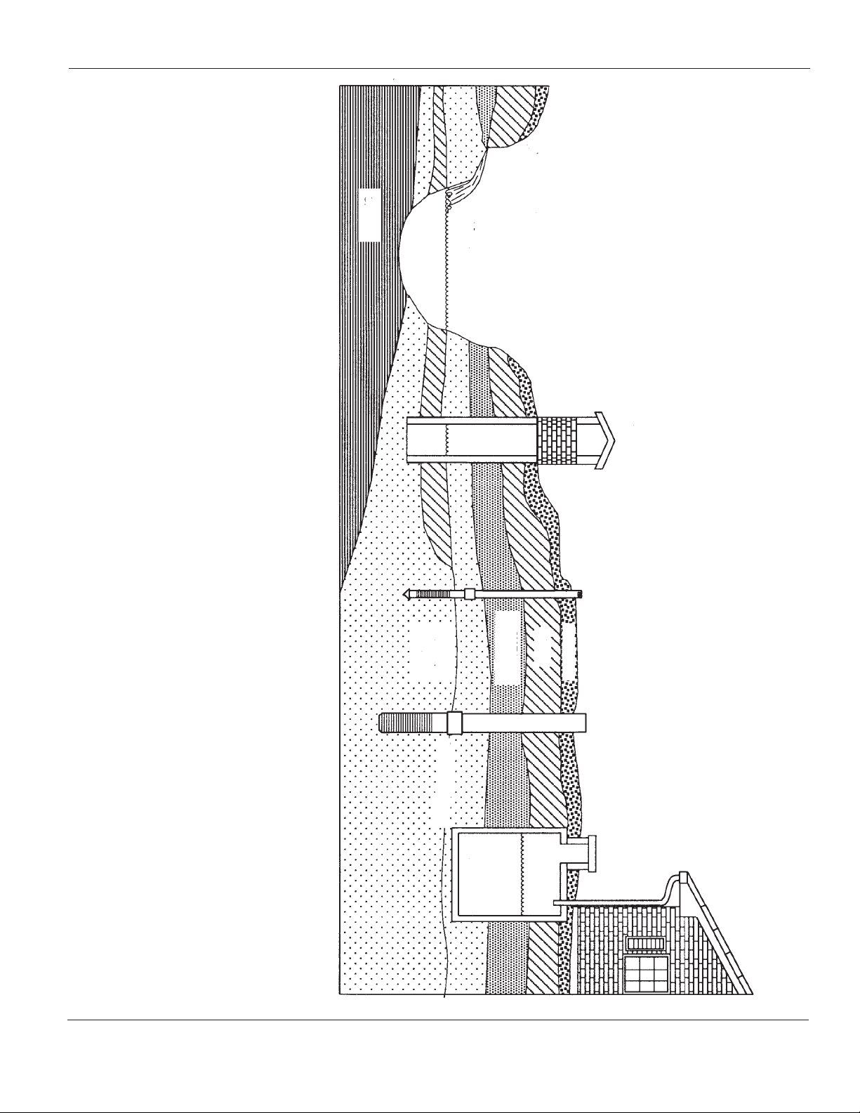
Figure 11 - Water Supplies
(A) SPRING:
A spring that emerges
from the ground.
Occurs when water in
permeable materials is
trapped between
impermeable
material as rock or clay.
(B) LAKE, STREAM or POND:
Surface water, unless treated,
is usually not safe for human
consumption. It may be used
for purposes such as washing
or irrigation.
(C) DUG WELL:
A hole is excavated
several feet in diameter
to a fairly shallow
depth. It is then lined
with brick, stone or
concrete to prevent
cave-in.
SHALE
(A) SPRING
(B) LAKE,
STREAM, POND
(C) DUG WELL
Water Supplies
the ground below
the water table.
The depth is usually
less than 50 feet.
Available
diameters are
1" through 2".
lined with pipe. Depths
range from a few feet
to over 1000 feet.
Common well diameters
are 2", 3", 4" and 6" for
domestic water wells.
water from rooftops.
The water is not fit
for human consumption.
(D) DRIVEN WELL:
Pipe with a pointed
screen is driven into
(E) DRILLED WELL:
A hole bored into the
earth with machinery and
(F) CISTERN:
An underground tank
built to collect rain
BEARING
SAND
WATER
WATER TABLE
PERMEABLE
MATERIAL
CLAY
(D) DRIVEN WELL
TOP SOIL
(E) DRILLED WELL
(F) CISTERN
www.waynepumps.com
7
Page 8
Operating Instructions and Parts Manual
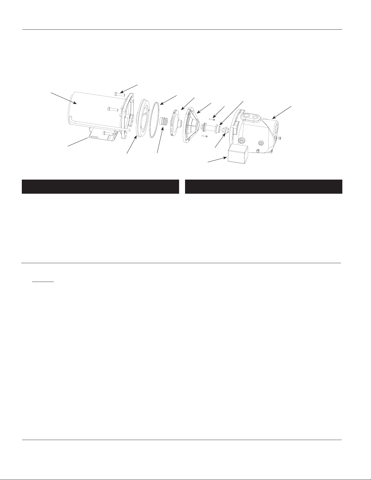
For Replacement Parts, Call 1-800-237-0987
Please provide following information: Address any correspondence to:
- Model number WAYNE Water Systems
- Serial number (if any) 101 Production Drive
- Part description and number as shown in parts list Harrison, OH 45030 U.S.A.
2
1
3
5
6
7
8, 9
JSU50
12
13
15
4
10
14
NOTE: Only use factory parts to repair this pump.
Ref.
No. Description
1 Motor 32059-001 1
2 Screw 16636-002 4
3 Square ring rubber gasket 17150-001 1
4 Shaft seal assembly 56393 1
5 Impeller 23285-002 1
6 Diffuser 17148-001 1
7 Screw 17165-001 2
8 O-ring 15557 1
Part
No. Qty.
Ref.
No. Description
9 Venturi 17151-002 1
10 Nozzle 15672 1
† 11 3/4” Pipe plug 15921 1
12 Pump housing 41033-001 1
13 Base 23029-001 1
14 Pressure switch 30010-001 1
15 Seal Plate 4372-001 1
† Not Shown
Part
No. Qty.
Limited Warranty
For one year from the date of purchase, WAYNE Water Systems (“WAYNE”) will repair or replace, at its option, for the
original purchaser any part or parts of its Sump Pumps or Water Pumps (“Product”) found upon examination by WAYNE to be
defective in materials or workmanship. Please call WAYNE (800-237-0987) for instructions or see your dealer. Be prepared to
provide the model number when exercising this warranty. All transportation charges on Products or parts submitted for repair
or replacement must be paid by purchaser.
This Limited Warranty does not cover Products which have been damaged as a result of accident, abuse, misuse, neglect,
improper installation, improper maintenance, or failure to operate in accordance with WAYNE's written instructions.
THERE IS NO OTHER EXPRESS WARRANTY. IMPLIED WARRANTIES, INCLUDING THOSE OF MERCHANTABILITY AND
FITNESS FOR A PARTICULAR PURPOSE, ARE LIMITED TO ONE YEAR FROM THE DATE OF PURCHASE. THIS IS THE
EXCLUSIVE REMEDY AND ANY LIABILITY FOR ANY AND ALL INDIRECT OR CONSEQUENTIAL DAMAGES OR EXPENSES
WHATSOEVER IS EXCLUDED.
Some states do not allow limitations on how long an implied warranty lasts, or do not allow the exclusions or limitations of
incidental or consequential damages, so the above limitations might not apply to you. This limited warranty gives you specific
legal rights, and you may also have other legal rights which vary from state to state.
In no event, whether as a result of breach of contract warranty, tort (including negligence) or otherwise, shall WAYNE or its
suppliers be liable for any special, consequential, incidental or penal damages including, but not limited to loss of profit or
revenues, loss of use of the products or any associated equipment, damage to associated equipment, cost of capital, cost of
substitute products, facilities, services or replacement power, downtime costs, or claims of buyer’s customers for such damages.
You MUST retain your purchase receipt along with this form. In the event you need to exercise a warranty claim, you MUST
send a copy of the purchase receipt along with the material or correspondence. Please call WAYNE (800-237-0987) for return
authorization and instructions.
DO NOT MAIL THIS FORM TO WAYNE. Use this form only to maintain your records.
MODEL NO. _____________________ SERIAL NO. ________________________ INSTALLATION DATE _____________________
ATTACH YOUR RECEIPT HERE
www.waynepumps.com
8
Page 9

Instructions D’utilisation et Manual de Pièces JSU50
Veuillez lire et conserver ces instructions. Lire attentivement avant de commencer à assembler, installer, faire fonctionner ou entretenir
l'appareil décrit. Protégez-vous et les autres en observant toutes les informations sur la sécurité. Négliger d'appliquer ces instructions peut
résulter en des blessures corporelles et/ou en des dommages matériels ! Conserver ces instructions pour références ultérieures.
Pompe À Jet
Description
Ces pompes domestiques à une étage
sont conçues pour le pompage d’eau
potable. Les pompes pour puits de
surface sont fabriquées pour les
applications là où le niveau d’eau
est moins de 7,62 m (25 pi) sous la
pompe. N’utilisez jamais de liquides
inflammables tels que l’essence, les
produits chimiques, ni les liquides
corrosifs avec cette pompe.
Déballage
Vérifiez cette unité avant de
l’utilisation. Parfois, un produit peut
être endommagé pendant le transport.
Si la pompe ou les composants sont
endommagés, contacter le service
clientèle au 1-800-237-0987.
Directives de Sécurité
Ce manuel contient de l’information
très importante de connaître et de
savoir qui est fournie pour la SÉCURITÉ
et pour ÉVITER LES PROBLÈMES
D’ÉQUIPEMENT. Rechercher les symboles
suivants pour cette information.
Danger indique une
situation
hasardeuse imminente qui RÉSULTERA
en perte de vie ou blessures graves.
Avertissement
indique une
situation hasardeuse potentielle
qui PEUT résulter en perte de vie ou
blessures graves.
Attention indique
une situation
hasardeuse potentielle qui PEUT résulter
en blessures.
Avis indique de
l’information
importante pour ÉVITER le dommage de
l’équipement.
REMARQUE : Information qui exige
une attention spéciale.
Généralités Sur La
Sécurité
PROPOSITION 65 DE CALIFORNIE
Ce produit ou son
cordon peuvent
contenir des produits chimiques qui, de
l’avis de l’État de Californie, causent le
cancer et des anomalies congénitales ou
autres problèmes de reproduction. Lavezvous les mains après la manipulation.
1. Lire attentivement ces instructions
et directives. Manque de suivre
ces instructions PEUT résulter en
blessures graves et/ou en dégâts
matériels.
Cette pompe n’est
pas submersible.
Installer seulement
à l’intérieur ou
dans une station de pompage. Installer
à l’intérieur seulement
Pomper l’eau claire
seulement. NE PAS pomper
les liquides inflammables
ou explosifs tels que l’essence,
l’huile à chauffage, le kérosène, etc.
NE PAS utiliser dans un atmosphère
inflammable et/ou explosif. Des
blessures et/ou des dommages à la
propriété SERONT causés.
Cette pompe n’est
pas conçue pour
les substances qui contiennent les
produits chimiques caustiques et/
ou les matières étrangères tels que
l’eau salée, la saumure, le décharge de
buanderie. L’utilisation de ces produits
PEUT endommager la pompe et NIERA la
garantie.
Toute installation de fils
doit être effectuée par un
électricien qualifié. La pompe
doit être installée conformément au
code National Electrical Code ainsi
qu’aux codes locaux.
2. Connecter cette pompe à un circuit
mis à la terre équipé d’un appareil
qui protège contre un dérangement
dû à une mise accidentelle à la terre
(DDFT).
3. Avant d’installer ce produit, faire
inspecter le circuit électrique par un
électricien qualifié afin d’assurer la
mise à la terre correcte.
RRisque de choc électrique! La
pompe doit être déconnectée
de la source d’alimentation
avant l’installation ou le service.
4. S’assurer que la source d’eau et la
tuyauterie soient libres de sable,
saleté et dépôts. Le débris peut
obstruer la pompe et annulera la
garantie.
5. Protéger la pompe et la tuyauterie
contre le gel. Manque de protéger
le produit contre le gel PEUT causer
du dommage sérieux et niera la
garantie.
6. Suivre les instruction d’amorçage. NE
PAS faire fonctionner la pompe au
sec.
Installation
Protéger la pompe contre les éléments.
Installer la pompe dans un sous-sol,
un garage, une cabane à outils, ou
un bâtiment pour pompes. Installer la
pompe pour que la ligne centrale de
la pompe soit aussi près que possible
MÉMENTO: Gardez votre preuve datée d'achat à fin de la garantie!
Joignez-la à ce manuel ou classez-la dans un dossier pour plus de sécurité.
© 2011, WAYNE/Scott Fetzer Company. 311405-001 6/11
9-Fr
Page 10

Instructions D’utilisation et Manual de Pièces JSU50
Installation (Suite)
du niveau d’eau. Garder l’endroit
d’installation libre d’obstructions afin
de permettre l’accès à la pompe pour
le service et l’entretien. Protéger la
pompe contre l’inondation et l’humidité
excessive.
Assurer l’aération suffisante de la
pompe. La température ambiante ne
doit pas dépasser 38˚C. Ceci peut causer
le déclenchement du protecteur de
surcharge thermique sur le moteur.
INSTALLATION DE TUYAUX DE
POMPE
Utiliser des tuyaux nouveaux pour un
meilleur résultat. Utiliser les tuyaux
en fer, cuivre ou CPV. Pour éviter la
tension sur la pompe si vous utilisez
des tuyaux en fer ou en cuivre, fournir
des supports indépendants pour les
tuyaux d’aspiration et de décharge
à proximité de la pompe. Diminuer
l’usage des coudes et des raccordements
afin de réduire la perte par frottement.
Se référer au tableau de perte par
frottement pour plus de renseignements
(Page 13 Fr). Augmenter le diamètre du
tuyau d’aspiration ou de décharge si la
longueur dépasse 15 m.
À LA
TUYAUTERIE
D’EAU
AU
PUITS
OU
RÉSERVOIR À
EAU
Figure 1 - Installation de Tuyaux
TUYAU D’ASPIRATION
Installer un
clapet de pied ou
un tamis de filtre sur l’arrivée du tuyau
d’aspiration.
Ne jamais utiliser un tuyau d’aspiration
avec un diamètre moins de 1-1/4 po.
Garder le tuyau d’aspiration libre
de fuites d’air. Pour l’installation
horizontale, placer le tuyau de la
source d’eau de manière qui permet
que le tuyau s’incline vers le haut à au
moins 1/2 po par pied pour éliminer
l’air emprisonné. L’arrivée filetée de la
pompe est 1-1/4 po NPT.
N’installez pas les
près des endroits de natation.
tuyaux d’aspiration
TUYAU DE DÉCHARGE (FIGURE 2)
Installer une croix de tuyau de 3/4 po
(vendue séparément) dans le décharge
de la pompe. Boucher la partie
supérieure de la croix de tuyau avec un
bouchon mâle de tuyau de 3/4 po NPT
(vendu séparément). Introduire le tuyau
du réservoir dans l’ouverture latérale
de la croix de tuyau. Insérer le tuyau
dans l’ouverture de côté restante pour
une connexion à la ligne d’alimentation
d’eau domestique.
CONDUITE VERS LE SYSTÈME
D’EAU DOMESTIQUE
CROIX DE
TUYAUS
TUYAU AU
RESERVOIR
Figure 2
CONNEXION DU CONTRÔLE
DE VOLUME D’AIR
BOUCHON
D’AMORÇAGE
RACCORDEMENT AU RÉSERVOIR
RÉSERVOIR TRADITIONNEL
(FIGURES 3 & 4)
Un réservoir traditionnel sert à
entreposer l’eau et l’air comprimé dans
le même compartiment. Au plein, le
réservoir contient approximativement
2/3 eau et 1/3 d’air comprimé. Ce type
de réservoir requiert un contrôle de
volume d’air qui remplace l’air perdu
automatiquement lors d’une fuite ou
d’absorption dans l’eau.
1. Couper la puissance à la pompe.
Débrancher et verrouiller la source
d’alimentation.
2. Purger le réservoir. Utiliser le robinet
plus près du réservoir.
3. S’assurer que le réservoir soit fixé
avec sûreté au plancher ou à la base.
4. Boulonner la pompe au plancher
ou sur le support de fixation du
réservoir.
BOUCHON
MANOSTAT
RACCORD DE
VIDANGE
TUYAU DE
CONTRÔLE
DE VOLUME
D’AIR
Figure 3 - Pompe pour Puits de Surface
avec Réservoir Horizontal Traditionnel
CONTRÔLE
DE VOLUME
D’AIR
TUYAU DE CONTRÔLE DE
VOLUME D’AIR
RACCORD
DE VIDANGE
Figure 4 - Pompe pour Puits de Surface
avec Réservoir Vertical Traditionnel
D’AMORÇAGE
ARRIVÉE
CONTRÔLE DE
VOLUME D’AIR
BOUCHON
D’AMORÇAGE
ARRIVÉE
5. Monter un contrôle de volume d’air
sur le réservoir.
6. Connecter le tube du contrôle de
volume d’air à l’ouverture latérale/
avant de 1/8 po NPT sur la pompe.
Les raccordements doivent être
serrés. Les fuites peuvent empêcher
l’amorçage et/ou peut saturer le
réservoir.
7. Installer une soupape et un tuyau
isolateur entre le réservoir et la
plomberie de maison afin de réduire
le niveau de bruit du système et de
faciliter le service.
8. Fournir un robinet de tuyau à
l’endroit le plus bas dans le système
pour vidanger le système pendant le
service ou l’entreposage.
9. Incliner les lignes horizontaux en
haut vers la pompe, un minimum
de 1/4 po par pied afin d’empêcher
d’emprisonner l’air dans les lignes.
10-Fr
Page 11

Instructions D’utilisation et Manual de Pièces JSU50
Installation (Suite)
MANOSTAT
SouPAPe d’Air
(193 À 207 KPA (28-30 PSi))
1/2 HP, 3/4 HP, eT 1 HP
Figure 5 - Pompe pour Puits de
Surface, Réservoir Chargé d’Avance
RÉSERVOIR CHARGÉ D’AVANCE
(FIGURE 5)
Un réservoir d’eau chargé d’avance
contient de l’air et de l’eau dans des
compartiments séparés par une vessie
flexible. La barrière empêche l’absorption d’air dans l’eau. La conception
de vessie permet l’usage d’eau sous
des pressions plus élevées et de temps
prolongé par rapport à un réservoir
traditionnel. Les réservoirs chargés
d’avance ont presque le double de
capacité utilisable par rapport à un
réservoir traditionnel qui comporte
un volume égal. La pression d’air dans
un réservoir chargé d’avance doit être
vérifiée de temps en temps pour assurer
un niveau correct (Se référer à la section
Entretien).
1. Couper la puissance à la pompe.
Débrancher et verrouiller la source
d’alimentation.
2. Purger le réservoir. Ouvrir le robinet
le plus près du réservoir.
3. S’assurer que le réservoir soit fixé au
plancher ou à la base.
4. Boulonner la pompe au plancher
ou au support de fixation sur le
réservoir.
5. Régler la pression d’air dans le
réservoir au niveau désiré. Une
soupape d’air est située sur le côté et
acceptera un raccord standard pour
pompe à vélo ou canalisation d’air.
6. Installer une soupape et un tuyau
isolateur entre le réservoir et la
plomberie de maison pour réduire
BOUCHON
D’AMORÇAGE
ARRIVÉE
RACCORD
DE
VIDANGE
le niveau de bruit du système et de
faciliter le service.
7. Fournir un robinet de tuyau à
l’endroit le plus bas du système
pour vidanger le système pendant le
service ou l’entreposage.
8. Incliner les lignes horizontaux en
haut vers la pompe, un minimum
de 1/4 po par pied afin d’empêcher
d’emprisonner l’air dans les lignes.
CONNEXION ÉLECTRIQUE
La tension de la source d’alimentation
doit correspondre avec la tension de la
pompe. Les pompes de puits de surface,
couvertes dans ce manuel, ont des
moteurs à tension double préréglés en
usine à 115 volts. Les modèles peuvent
être transformés à 230 volts en tournant
le sélecteur de tension à la tension
désirée (Voir la Figure 6). Utiliser des
pinces à long bec et tirer le sélecteur
environ 6,4 mm, tourner, et le fixer dans
la position correcte.
Figure 6 - Sélecteur de Tension
Connecter la pompe à un circuit
électrique unique avec un disjoncteur
unique. Se référer aux descriptions
précises électriques dans le tableau
d’installation de fils pour le circuit et les
tailles de fils recommandés (à la page
13).
Installer et
entretenir les fils
pour cette pompe conformément au
National Electrical Code tous les autres
codes applicables.
Le moteur doit être mis à la terre en
branchant un fil en cuivre à la vis de
terre fournie dans le compartiment
d’installation de fils du manostat.
Le compartiment d’installation de
fils au champ pour le pompe à jet est
dans le carter du manostat. Il existe
seulement une vis de mise à la terre
sur le modèle. La vis est située sous le
couvercle du manostat, est peinturée
verte et est indiquée par les lettres GRD.
La connexion de mise à la terre doit être
à cette borne (Figure 7).
Se référer au schéma d’installation de
fils situé sous le couvercle du manostat
(Aussi sur la Figure 7).
LIGNE
FIXER LE
FIL DE
TERRE
ICI
Figure 7 - Connexions Électriques
1
L1
3
L2
MOTEUR
Pour fixer le c.a. au pressostat, s’assurer
d’abord que le circuit a été mis hors
tension. Desserrer la vis qui maintient le
couvercle sur le pressostat puis retirer le
couvercle.
Desserrer la vis de terre inutilisée et
fixer la partie exposée du fil de terre
entre la tête de vis et le corps du
manostat, puis resserrer.
Desserrer les deux vis supérieures du
manostat et resserrer avec les fils du
courant de c.a saisis sous les têtes de vis.
Replacer le couvercle du manostat et
resserrer la vis.
BRANCHEMENT A LA SOURCE D’EAU
PUITS ENFONCÉ
1. Enfoncer le point plusieurs pieds
sous le niveau hydrostatique.
Remarque: Un clapet de pied
d’étanchéité peut être installé dans le
puits (Figure 8). Ce type de clapet de
pied permet que le tuyau de puits se
remplisse d’eau pendant l’amorçage et
facilite la recherche des fuites. Suivre
les instructions du fabricant pendant
l’installation du clapet de pied.
En option, un clapet en canalisation
peut être utilisé avec les puits enfoncés
(Figure 9).
NE PAS utiliser
de pied dans votre système. Ceci PEUT
diminuer le rendement de la pompe.
de clapet et clapet
11-Fr
Page 12

Instructions D’utilisation et Manual de Pièces JSU50
Installation (Suite)
À LA POMPE
D’ENFONCEMENT
POINT
Figure 8 - Clapet de pied d’étanchéité
À LA
POMPE
CLAPET EN
CANALISATION
POINT
D’ENFONCEMENT
Figure 9 - Clapet En Canalisation
À LA
POMPE
CLAPET
DE PIED
Figure 10 - Joint de Puits
CLAPET DE PIED
D’ÉTANCHÉITÉ
JOINT DE
PUITS
COFFRAGE
DE PUITS
PUITS FORÉ
1. Installer un clapet de pied sur la
première section de tuyau (Figure
10).
2. Baisser le tuyau dans le puits.
3. Ajouter des tuyaux jusqu’à ce que le
clapet soit 3 m sous le niveau d’eau
plus bas possible.
Des fuites dans les joints ou
accouplements permettront une fuite
d’air dans le tuyau et résultera en
mauvais fonctionnement de la pompe.
S’assurer d’utiliser de la pâte à joint ou
du ruban adhésif de plombier sur toutes
les connexions de tuyau.
Placer le clapet de
pied au moins 0,61
m du fond du puits pour EMPÊCHER
l’aspiration de sable ou de sédiment
dans le système.
4. Une fois que la profondeur correct
est atteinte, installer un joint de
puits ou adaptateur pour soutenir le
tuyau.
5. Incliner le tuyau horizontal en
haut vers la pompe pour empêcher
d’emprisonner l’air.
INSTALLATION POUR PUITS CREUSÉS,
CITERNES, LACS ET SOURCES
1. Installer un clapet de pied sur le
tuyau d’arrivée et le baisser dans
l’eau.
Placer le clapet de
pied au moins 0,61
m du fond du puits pour EMPÊCHER
l’aspiration de sable ou de sédiment
dans le système.
REMARQUE: Si un lac est la source
d’eau, s’assurer que le tuyau
d’aspiration est assez profond pour
qu’il soit toujours immergé. Incliner le
tuyau en haut vers la pompe pour éviter
d’emprisonner l’air. Enlever le tuyau
pendant l’hiver ou le protéger contre le
gel.
Protéger le tuyau
contre le dommage
causé par les nageurs et les bateaux.
Fonctionnement
AMORÇAGE DE LA POMPE
NE PAS faire
fonctionner la
pompe au sec. Remplir la pompe
d’eau avant le démarrage du moteur,
sinon, les joints de la pompe SERONT
endommagés et la garantie annulée.
Une fois que l’installation de la pompe
est terminée, la pompe doit être
amorcée.
1. Enlever le bouchon d’amorçage.
2. Remplir la pompe et les tuyaux
complètement d’eau.
3. Remplacer le bouchon d’amorçage.
4. Ouvrir le robinet pour aérer le
système.
5. Démarrer le moteur. L’eau sera
pompée dans quelques minutes. Si la
pompe ne pompe pas d’eau pendant
5 minutes, arrêter le moteur et
retourner à l’étape 1.
6. Laisser le système fonctionner
pendant plusieurs minutes afin de
faire la chasse d’eau des tuyaux.
7. Fermer le robinet et permettre que
la pompe augmente la pression dans
le réservoir. Le moteur s’arrêtera
quand la pression atteint le réglage
d’arrêt.
Le système fonctionne et s’actionnera
au besoin.
Si la pompe ne fonctionne pas après
plusieurs essais, vérifier que:
1. La distance verticale de la pompe à
l’eau ne dépasse pas 7,62 m.
2. Le tuyau d’aspiration doit être
étanche.
3. Les soupapes doivent être ouvertes si
utilisées dans les tuyaux de décharge
ou d’aspiration.
NE JAMAIS faire
fonctionner la
pompe avec un décharge fermé ou
obstrué. L’eau dans la pompe peut
bouillir et endommager la pompe.
L’utilisation d’un clapet de pied
est recommandé. Ceci permet le
remplissage de la ligne d’aspiration
pendant l’amorçage et réduit le temps
d’amorçage.
12-Fr
Page 13

Instructions D’utilisation et Manual de Pièces JSU50
Entretien
Débrancher la source
d’alimentation et dissiper
toute la pression du
système avant d’essayer d’installer
de déplacer, ou de procéder au
service ou à l’entretien. Verrouiller
le sectionneur de puissance dans la
position open/off (ouvert/hors circuit).
Etiqueter le sectionneur de puissance
afin d’empêcher une application de
puissance inattendue. Ceci PEUT causer
des blessures graves ou la mort.
Maintenir la ventilation suffisante pour
le moteur de la pompe. Les roulements
de moteur sont lubrifiés en permanence
à l’usine. Le graissage n’est pas requiert.
VIDANGE DU POMPE
Des ouvertures pour la vidange sont
fournies sur tous les modèles. Pour
vidanger la pompe:
1. Mettre la pompe hors tension.
2. Enlever le raccord de vidange et le
bouchon d’amorçage.
3. Purger tous les tuyaux jusqu’à un
point sous le niveau de gelée.
VIDANGE DU RÉSERVOIR
Vidanger les réservoirs traditionnels
en ouvrant un orifice de sortie au
point plus bas du système. Enlever un
bouchon ou le contrôle de volume d’air
pour aérer le réservoir.
Les réservoirs chargés d’avance forcent
toute l’eau du réservoir quand la
pression du système est relâchée. Le
vidange n’est pas nécessaire.
RÉSERVOIRS PLEIN D’EAU
RÉSERVOIRS TRADITIONNELS
Si un système de réservoir a une
proportion insuffisante d’air et d’eau,
la pompe se démarrera et s’arrêtera
souvent et irrégulièrement vant et
irrégulièrement.
1. Couper le courant à la pompe.
2. Ouvrir le robinet le plus bas du
système pour dissiper toute la
pression.
3. Amorcer la pompe.
4. Connecter à nouveau la source
d’énergie électrique.
Quand la pompe remplit le réservoir,
le contrôle de volume d’air fournit au
réservoir la proportion correcte d’air
et d’eau. Ensuite la pompe s’arrête
à la pression désirée. Si le réservoir
se remplit d’eau encore, inspecter le
contrôle de volume d’air et le remplacer
si nécessaire.
RÉSERVOIRS CHARGÉS D’AVANCE
Si un réservoir chargé d’avance devient
plein d’eau, il y a probablement une
fuite ou rupture dans la vessie.
1. Faire l’essai du réservoir en appuyant
sur la soupape d’air. La soupape
déchargera l’eau si la vessie s’est
éclatée.
2. Remplacer le réservoir si la vessie a
éclatée.
Si la vessie de réservoir a éclatée,
le réservoir doit être remplacé. La
réparation de la vessie n’est pas
recommandée, et peut causer d’autres
problèmes tels que le plein d’eau dans
le réservoir, les débris dans les tuyaux et
une décharge obstruée dans le réservoir.
VÉRFIFICATION DE PRESSION D’AIR
POUR LES RÉSERVOIRS CHARGÉS
D’AVANCE
Un peu de perte d’air est normal dans
un réservoir. Pour empêcher la panne et
pour l’entretien correct d’un réservoir
chargé d’avance, vérifier la pression
annuellement.
1. Déconnecter l’énergie à la pompe.
2. Ouvrir le robinet plus près du
réservoir et purger l’eau du réservoir.
3. Mesurer la charge du réservoir à
la tige de soupape en utilisant un
manomètre pour pneus.
4. Si nécessaire, régler la charge
avec une pompe à air: La pression
préchargée pour cette pompe est de
193 à 207 kPa (28 à 30 lb/po²).
5. Amorcer la pompe.
6. Connecter à nouveau l’énergie.
7. Fermer le robinet.
RENCOMMANDATIONS DE FUSIBLES ET DE FILS – MOTEURS DE 60 HZ
Distance en pieds Mètre à Moteur
Fusible à
élément
HP VOLT
115 15 14 12 10 8
1/2
230 10 14 14 14 14
double
250V
0 51 101 201
to to to to
50 100 200 300
Taille de fils
TABLEAU DE PERTES PAR FROTTEMENT
Perte par frottement en 30,5 m de tuyau en plastique
Taille de
Tuyau
75,7 94,6 113,6 151,4 189,3 227,1 302,8 378,5 454,3
Litres par minute
3,2 cm 21,2 32,2 45,1 76,5 115,5
3,8 9,8 15,1 20,8 35,6 54,1 75,3 129,5
5,1 4,5 6,1 10,6 15,9 22,0 37,5 56,8 80,3
6,4 4,5 6,8 9,5 15,9 23,9 33,3
13-Fr
Page 14

Instructions D’utilisation et Manual de Pièces JSU50
Tableau de dépannage
Symptôme Cause(s) Possible(s) Mesures Correctives
Moteur ne
fonctionne
Moteur fonctionne
chaud et le
surcharge se
déclenche.
Moteur ronron mais
ne fonctionne pas
Moteur fonctionne
mais délivre peu ou
pas d’eau
Remarque: Vérifier
l’amorçage avant de
rechercher d’autres
causes. Desserrer le
bouchon d’amorçage
et vérifier qu’il y ait
de l’eau dans le trou
d’amorçage
Pompe s’arrête et
se démarre trop
souvant
1. Source de puissance hors-circuit 1. Mettre en marche ou contacter la compagnie de service
publique
2. Fusible sauté (Disjoncteur
2. Remplacer le fusible (Réenclencher le disjoncteur)
enclenché)
3. Fils au manostat sont desserrés,
déconnectés, ou mal installés
3. Se référer aux instructions d’installation de fils. Vérifier et serrer
tous les fils
Wires at p
4. Manostat défectueux 4. Remplacer le manostat
5. Protecteur thermique du
moteur enclenché
5. Laisser refroidir. Protecteur s’enclenche automatiquement.
Fournir un endroit ombreux, et bien ventilé pour la pompe
1. Fils du manostat mal installés5. 1. Se référer aux instructions d’installation de fils
2. Tension trop basse 2. Vérifier la tension de ligne. Installer des fils de calibre plus élevé
si la taille de fils est trop petite (Voir le tableau d’installation de
fils, page 13 Fr). Consulter la compagnie de service publique
3. Cyclage rapide 3. Vérifier le pressostat. S’assurer que le réservoir ne soit pas plein
d’eau.
4. Température ambiante élevée 4. Fournir un endroit ombreux, et bien ventilé pour la pompe
1. Installation de fils du moteur
1. Se référer aux instructions d’installation de fils
incorrect
2. Tension trop basse 2. Vérifier la tension de ligne. Installer du fil de calibre plus élevé
si la taille de fils est trop petite (Voir le tableau d’installation de
fils, page 13 Fr). Vérifier avec la compagnie de service publique
3. Impulseur obstrué 3. Desconecte la corriente. Con un destornillador plano intente
rotar el eje del motor (ubicado bajo la tapa plástica en la parte
posterior del motor). Si el eje no rota libremente, quite la
obstrucción del impulsor.
4. Sélecteur de tension mal réglé 4. Fije el interruptor selector de voltaje (Figura 6) para que
coincida con el voltaje de línea. (Consulte las conexiones
eléctricas en la página 11)
1. Nouvelle pompe ne s’amorce
1. Nouvelle installation:
pas à cause de:
a. l’amorçage incorrect a. Amorcer de nouveau selon les instructions
b. fuites d’air b. Vérifier les branchements sur la ligne d’aspiration
c. fuites au clapet de pied c. Remplacer le clapet de pied
2. Pompe perd l’amorçage à cause
2. Installation présente:
de:
a. fuites d’air a. Vérifier les branchements sur la ligne d’aspiration et le joint
d’arbre
b. niveau d’eau sous l’aspiration
de la pompe
b. Baisser la ligne d’aspiration dans l’eau et amorcer de
nouveau. Si le niveau d’eau dans le puits dépase la hauteur
d’aspiration, une pompe à puits profonde est nécessaire
3. L'impulseur est obstrué 3. Nettoyer la turbine
4. Clapet ou clapet de pied pris
4. Remplacer le clapet ou le clapet de pied
dans la position fermée
5. Tuyaux gelés 5. Dégeler les tuyaux. Enterrer les tuyaux sous le niveau de gel.
Chauffer le trou ou la cabane de la pompe
6. Clapet de pied et/ou tamis
enfouis dans le sable ou la boue
1. Réservoir plein d’eau (réservoir
6. Élever le clapet de pied et/ou le tamis par dessus le fond du
puits
1. Respecter les directives dans la section entretien (à la page 13)
traditionnel)
2. Diaphragme ou vessie rupturé
2. Remplacer le réservoir
(Réservoir chargé d’avance)
3. Contrôle de volume d’air
3. Déplacer à l’orifice correcte
branché au mauvais orifice de la
pompe
4. Charge du réservoir incorrect
4. Ajouter ou dissiper l’air au besoin
(Réservoir chargé d’avance)
5. Fuite dans le système ou dans la
5. Situer et réparer la fuite
tuyauterie de maison
6. Clapet de pied ou clapet pris
6. Remplacer la soupape
dans la position ouverte
7. Manostat mal réglé 7. Régler ou remplacer le manostat
14-Fr
Page 15

Instructions D’utilisation et Manual de Pièces JSU50
Figure 11 - Sources d'Eau
quand l’eau dans les
matériaux perméables
est pris entre les
matériaux imperméables
tels que la roche ou
l’argile.
généralement impropre à
la consommation humaine
sans traitement. Cette eau
peut être utilisée pour le
lavage ou l’irrigation.
plusieurs centimètres
de diamètre à une
distance peu profonde.
Le trou est cuvelé de
briques, pierres ou
béton pour empêcher
que le trou s’effonde.
(A) SOURCE D’EAU:
Eau qui sort de la terre
SCHISTEUSE
ARGILE
(B) LAC, RUISSEAU, ÉTANG:
L’eau de surface est
(C) PUITS CREUSÉ:
Un trou est creusé
(B) LAC,
RUISSEAU, ÉTANG
(A) SOURCE D'EAU
(C) PUITS CREUSÉ
Un tuyau avec un
tamis pointu est
enfoncé dans la terre
sous le niveau
hydrostatique. La
profondeur est
généralement moins
de 15 m. Les diamètres
disponibles sont
2,5 cm à 5,1 cm.
Un trou foré dans la
terre avec une machine
et cuvelé d’un tuyau.
La gamme de profondeurs
est de plusieurs centimètres
à 305 m. Les diamètres de
puits ordinaires sont
5,1 cm (2"), 7,6 cm (3"),
10,2 cm (4") et 15,2 cm (6")
pour les puits domestiques.
Un réservoir souterrain
fabriqué pour la
collection de pluie des
toits. Cette eau est
impropre à la
consommation humaine.
(D) PUITS ENFONCÉ:
(E) PUITS FORÉ:
(F) RÉSERVOIR À EAU:
AQUIFORE
SABLE
HYDROSTATIQUE
NIVEAU
PERMÉABLE
MATÉRIEL
ARGILE
(D) PUITS ENFONCÉ
COUCH
ARABLE
(E) PUITS FORÉ
(F) RÉSERVOIR
À EAU
15-Fr
Page 16

Instructions D’utilisation et Manual de Pièces JSU50
Pour des Pièces de Rechange, composer 1-800-237-0987
S’il vous plaît fournir l’information suivante: Adresser toute correspondance à :
- Numéro de Modèle WAYNE Water Systems
- Numéro de série (si présent) 101 Production Drive
- Description et numéro de la pièce Harrison, OH 45030 U.S.A.
1
2
3
5
6
7
8, 9
12
13
15
4
10
14
NOTE: Utiliser seulement des pieces de l’usine pour reparer la pompe
No.
de
Réf.
Description No. de
1 Moteur 32059-001 1
2 Vis 16636-002 4
3 Joint de caoutchouc à anneau
carré
4 Assemblage de boîte
d'étanchéité
5 Rotor 23285-002 1
6 Diffuseur 17148-001 1
7 Vis 17165-001 2
8 Joint torique 15557 1
pièce Qté.
17150-001 1
56393 1
No.
de
Réf.
Description No. de
pièce Qté.
9 Venturi 17151-002 1
10 Buse 15672 1
† 11 Bouchon de tuyau 3/4 po 15921 1
12 Boîtier de pompe 41033-001 1
13 Base 23029-001 1
14 Manostat 30010-001 1
15 Plaque de joints 4372-001 1
† Pas indiqué
Garantie Limitée
Pour un an à compter de la date d’achat, WAYNE Water Systems (“WAYNE”) vas réparer ou remplacer, à son option, pour
l’acheteur originel n’importe quelle pièce ou pièces de ces Pompes De Puisard ou Pompes À Eau (“Produit”) déterminées
défectueuses, par WAYNE, en matière ou en fabrication. S’il vous plaît appeler WAYNE (800-237-0987) pour des instructions ou
contacter votre marchand. S’assurer d’avoir, à votre disposition, le numéro du modèle afin d’effectuer cette garantie. Les frais
de transportation des Produits ou pièces soumis pour la réparation ou le remplacement sont la responsabilité de l’acheteur.
Cette Garantie Limitée ne couvre pas les Produits qui se sont fait endommagés en résultat d’un accident, utilisation abusive,
mauvais usage, négligence, l’installation incorrecte, entretien incorrect, ou manque d’utilisation conformément aux
instructions écrit de WAYNE.
IL N’EXISTE AUCUNE AUTRE GARANTIE OU AFFIRMATION. LES GARANTIES EXPRIMÉES, Y COMPRIS CELLES DE
COMMERCIALISABILITÉ ET D’ADAPTION À UNE FONCTION PARTICULIÈRE, SONT LIMITÉES À UN AN À COMPTER DE
LA DATE D’ACHAT. CECI EST LA REMÈDE EXCLUSIVE ET N’IMPORTE QUELLE RESPONSABILITÉ POUR N’IMPORTE QUEL
ET TOUT DOMMAGES INDIRECTS OU DÉPENSES QUOI QUE SE SOIT EST EXCLUS.
Certaines Provinces n’autorisent pas de limitations de durée pour les garanties implicites, ni l’exclusion ni la limitation des
dommages fortuits ou indirects. Les limitations précédentes peuvent donc ne pas s’appliquer. Cette garantie limitée donne, à
l’acheteur, des droits légales précis, et vous pouvez avoir autres droits légales qui sont variable d’une Province ou d’un État à
l’autre.
En aucun cas, soit par suite d’un rupture de contrat de garantie, acte dommageable (y compris la négligence) ou autrement,
ni WAYNE ou ses fournisseurs seront responsables pour aucune dommage spéciale, incidentel ou pénal, y compris, mais pas
limité à la perte de profits ou recettes, la perte d’usage des produits ou n’importe quel équipement associé, dommage à
l’équipement associé, coût de capital, coût de produits remplaçants, aménagements, services ou abilité de remplaçement, coût
de temps que le produit n’est pas en service, ou la réclamation des clients de l’acheteur pour ces dommages.
Vous DEVEZ garder votre recette d’achat avec ce bulletin. Il est NÉCESSAIRE d’envoyer une copie de la recette d’achat avec
le matériel ou correspondance afin d’effectuer une réclamation de la garantie. S’il vous plaît appeler WAYNE (800-237-0987)
pour l’autorisation et instructions concernant le renvoi.
NE PAS ENVOYER, PAR LA POSTE, CE BULLETIN À WAYNE. Utiliser ce bulletin seulement pour vos archives.
Nº DU MODÈLE _____________________ Nº DE SÉRIE ________________________ DATE D’INSTALLATION _____________________
FIXER VOTRE FACTURE ICI
16-Fr
Page 17

Manual de instrucciones de operación y piezas JSU50
Por favor lea y guarde estas instrucciones. Léalas cuidadosamente antes de tratar de montar, instalar, operar o dar mantenimiento al producto
aquí descrito. Protéjase usted mismo y a los demás observando toda la información de seguridad. ¡El no cumplir con las instrucciones puede
ocasionar daños, tanto personales como a la propiedad! Guarde estas instrucciones para referencia en el futuro.
Bomba Eyectora
Descripción
Estas bombas son bombas de agua
de una etapa para uso doméstico,
diseñadas para bombear agua potable.
Las bombas para pozos de poca
profundidad están diseñadas para
aplicaciones en las que el nivel de agua
no exceda los 7,62 m (25 pies) debajo de
la bomba. Nunca use con estas bombas
fluidos inflamables, tales como gasolina,
químicos o corrosivos.
Para Desempacar
Revise esta unidad antes de usarla. A
veces, el producto puede sufrir daños
durante el transporte. Si la bomba o
sus componentes están dañados, llame
a Servicio al cliente, por el 1-800-237-
0987.
Medidas de Seguridad
Este manual contiene informacion
que es muy importante que sepa
y comprenda. Esta informacion se
la suministramos como medida de
SEGURIDAD y para EVITAR PROBLEMAS
CON EL EQUIPO. Ésto le indica que
hay una situación
inmediata que LE OCASIONARIA la
muerte o heridas de gravedad.
Ésto le indica
que hay una
situación que PODRIA ocasionarle la
muerte o heridas de gravedad.
Ésto le indica
que hay una
situación que PODRIA ocasionarle
heridas no muy graves.
Ésto le indica una
información
importante, que de NO SEGUIRLA, le
PODRÍA ocasionar daños al equipo.
NOTA: Información que requiere
atención especial.
Informaciones
Generales de Seguridad
PROPOSICIÓN 65 DE CALIFORNIA
Este producto, o su
cordón eléctrico,
puede contener productos químicos
conocidos por el estado de California
como causantes de cáncer y defectos de
nacimiento u otros daños reproductivos.
Lave sus manos después de usar.
1. Sírvase leer cuidadosamente todas
estas normas e instrucciones. El
no cumplir con estas instrucciones
PODRÍA provocar lesiones personales
y/o daños materiales.
Esta bomba no es
sumergible.
Instale únicamente
en interiores o
dentro de una construcción especial
para la bomba de agua. Existe riesgo de
un choque eléctrico.
Bombee sólo agua limpia,
NUNCA fluidos inflamables
o explosivos, tales como
gasolina, petróleo combustible,
kerosene, etc. NO la use en atmósferas
inflamables y/o explosivas. PROVOCARÁ
lesiones y/o daños a la propiedad.
Esta bomba
no ha sido diseñada
para controlar agua salada, salmuera,
descargas de lavandería o cualquier
otra aplicación que pueda contener
sustancias químicas cáusticas y/o
materias extrañas. PODRÍA producirse
daño en la bomba si se usa en estas
aplicaciones, INVALIDANDO la garantía.
Un electricista calificado
deberá realizar todo el
cableado. La bomba se debe
instalar de acuerdo al Código
Nacional de Electricidad y a todos los
códigos locales.
2. Conecte esta bomba a un circuito de
conexión a tierra equipado con un
interruptor de circuito de pérdida a
tierra (GFCI).
3. Antes de instalar este producto,
haga que un electricista verifique el
circuito eléctrico a fin de asegurar
una adecuada conexión a tierra.
¡Riesgo de choque eléctrico!
Desconecte siempre la fuente
de energía antes de instalar
la bomba o darle servicio.
4. Asegúrese de que la fuente de agua
y la tubería estén libres de arena,
suciedad y óxido. Los residuos
atorarán la bomba e invalidarán la
garantía.
5. Proteja la bomba y la tubería del
frío excesivo. El no protegerla del
frío PODRÍA causar un daño grave e
invalidaría la garantía.
6. Siga las instrucciones principales. NO
haga funcionar la bomba al seco.
Instalación
Proteja la bomba del medio ambiente
instalándola en un sótano, garaje,
depósito de herramientas o caja de
bombas. Instale la bomba de tal manera
que el eje de la misma esté lo más cerca
posible al nivel de agua. Mantenga
despejada el área de instalación a fin
de brindar servicio y mantenimiento.
Proteja la bomba de inundaciones y
humedad excesiva.
Asegúrese de que la bomba tenga una
ventilación adecuada. La temperatura
ambiental no debe exceder los 38˚C
puesto que podría ocasionar daños en el
RECORDATORIO: ¡Guarde su comprobante de compra con fecha para fines de la garantía!
Adjúntela a este manual o archívela en lugar seguro.
© 2011, WAYNE/Scott Fetzer Company. 311405-001 6/11
17-Sp
Page 18

Manual de instrucciones de operación y piezas JSU50
Instalación (Continúa)
accionador del protector de sobrecarga
térmico del motor.
INSTALACIÓN DE LA TUBERÍA DE LA
BOMB
Para mejores resultados use una tubería
nueva. Puede usarse tuberías de hierro,
cobre o PVC. Para evitar que la bomba
se deforme cuando utilice una tubería
de hierro o cobre, proporciónele
soporte independiente a la tubería de
succión y desagüe cerca de la bomba.
Reduzca al mínimo el uso de tubos
acodados y accesorios a fin de disminuir
la pérdida por rozamiento. Remítase
al cuadro de pérdida por rozamiento
para información específica (pg. 21 Sp).
Aumente el diámetro de la tubería de
succión o desagüe si es que la longitud
excede los 5,25 m (50 pies).
AL NIVEL
DE
AGUA
AL
POZO
O A LA
CISTERNA
Figura 1 - Instalación de la tubería
TUBERÍAS DE SUCCIÓN
Instale la válvula
de pie o el filtro
sobre la toma de las tuberías de succión.
Nunca utilice tuberías de diámetro
menor a 3,2 cm (1-1⁄4 “) para las
tuberías de succión. Asegúrese de que
la tubería de succión no tenga fugas de
aire. Para funcionamientos horizontales,
tienda la tubería desde el suministro de
agua para que la inclinación superior
sea de por lo menos fi pulg. por pie.
Esto evita que el aire quede atrapado.
La entrada roscada de la bomba mide
3,2 cm (1-1⁄4“) NPT.
No instale tuberías
áreas de natación.
de succión cerca de
TUBERÍAS DE DESCARGA (FIGURA 2)
Instale un conector en cruz de 19,1 mm
(3/4”) (no incluido con la unidad) en el
orificio de salida de la bomba. Cierre el
orificio de la parte superior del conector
con un tapón de 19,1 mm (3/4”) NPT
(no incluido con la unidad). Conecte la
tubería del tanque al orificio lateral del
conector en cruz. Inserte la tubería en la
abertura del lado restante para conectar
a la línea de suministro de agua en el
hogar.
TUBERÍAS CONECTADAS AL
SISTEMA DE AGUA DEL HOGAR
T DOBLE PARA
TUBERÍA
TAPÓN
DE
CEBADO
TUYAU DE
TANQUE
Figura 2
CONEXIÓN DE CONTROL
DE VOLUMEN DEL AIRE
CONEXIÓN AL TANQUE DE AGUA
TANQUE CONVENCIONAL (FIGURAS 3
& 4)
Un tanque de agua convencional
almacena agua y aire comprimido en
el mismo compartimiento. Cuando
el tanque está lleno, éste contiene
aproximadamente 2/3 de agua y 1/3 de
aire comprimido. Este tipo de tanque
requiere de un control de volumen de
aire debido a las fugas o absorciones en
el agua.
1. Desactive la energía eléctrica para
bombear. Desconecte y bloquee la
fuente de energía eléctrica.
2. Drene el tanque. Se recomienda la
llave de salida más cerca al tanque.
3. Cerciórese de que el tanque esté
seguro en el piso o la base.
4. Atornille la bomba en el piso o en el
soporte de montaje sobre el tanque.
5. Instale el control de volumen de aire
en el tanque.
6. Conecte el tubo del control de
volumen de aire a la salida frontal de
3,2 mm (1/8“ NPT) al costado de la
bomba. Las conexiones deben estar
bien ajustadas. Las fugas harán que
INTERRUPTOR
DE PRESIÓN
ADAPTADOR DE
DRENAJE
TUBERÍA DEL
CONTROL DE
VOLUMEN DE
AIRE
Figura 3 - Bomba de pozo de poca
profundidad con tanque horizontal
convencional
CONTROL DE
VOLUMEN DE AIRE
TUBERÍA DEL
CONTROL DE
VOLUMEN DE AIRE
ADAPTADOR
DE DRENAJE
Figura 4 - Bomba de pozo de poca
profundidad con tanque vertical
convencional
TAPÓN DE
CEBADO
ENTRADA
CONTROL DE
VOLUMEN DE AIRE
TAPÓN
DE
CEBADO
ENTRADA
la bomba no se cebe y/o el tanque se
inunde.
7. Instale una válvula y una manguera
aisladora entre el tanque y las
cañerías domésticas. Esto reducirá
el nivel de ruido del sistema
de la bomba y ayudará en el
mantenimiento.
8. Coloque un grifo de manguera
(llave) en el punto más bajo del
sistema para drenarlo a fin de darle
mantenimiento o almacenarlo.
9. Incline las líneas horizontales hacia
arriba con dirección a la bomba a
un mínimo de 6,4 mm (1/4”) por pie.
Esto evitará que se atrape aire en las
líneas.
TANQUE PRE-CARGADO (FIGURA 5)
Un tanque de agua pre-cargado
almacena aire y agua en
compartimientos distintos, separados
por una bolsa flexible. Esta barrera evita
18-Sp
Page 19

Manual de instrucciones de operación y piezas JSU50
Instalación (Continúa)
INTERRUPTOR
DE PRESIÓN
VálVulA de Aire
(1,9 A 2,1 BAr (28-30 PSi)) 1/2
HP, 3/4 HP, Y 1 HP
Figura 5 - Bomba de pozo de poca
profundidad con tanque pre-cargado
que se absorba aire en el agua. Este
diseño de bolsa también permite que se
ejerzan presiones mayores sobre el agua
durante periodos más prolongados que
en un tanque convencional. Los tanques
pre-cargados poseen aproximadamente
el doble de capacidad utilizable que la
que tiene un tanque convencional de
igual volumen. La presión de aire en
un tanque pre-cargado debe verificarse
periódicamente para cerciorarse de
que esté a un nivel aceptable (Vea
Mantenimiento).
1. Apague la energía eléctrica para
bombear. Desconecte y bloquee la
fuente de energía eléctrica.
2. Drene el tanque. Se recomienda la
llave de salida más cerca al tanque.
3. Cerciórese de que el tanque esté
seguro en el piso o la base.
4. Atornille la bomba al piso o en el
soporte de montaje sobre el tanque.
5. Ajuste la presión de aire al nivel
deseado. Una válvula de aire se
encuentra al costado y aceptará una
conexión estándar de una bomba de
bicicleta o línea de aire.
6. Instale una válvula y una manguera
aisladora entre el tanque y las
cañerías domésticas. Esto reducirá
el nivel de ruido del sistema
de la bomba y ayudará en el
mantenimiento.
7. Coloque un grifo de manguera
(llave) en el punto más bajo del
sistema para drenarlo a fin de darle
mantenimiento o almacenarlo.
TAPÓN DE
CEBADO
ENTRADA
ADAPTADOR
DE DRENAJE
8. Incline las líneas horizontales hacia
arriba con dirección a la bomba a
un mínimo de 6,4mm (1/4”) por pie.
Esto evitará que se atrape aire en las
líneas.
CONEXIÓNES ELÉCTRICAS
El voltaje de la fuente de suministro
eléctrico debe ser similar al de la bomba.
Las bombas para pozo de instalación
sobre superficie, referidas en este
manual, tienen motores de doble voltaje
preconfigurados en la fábrica a 115
voltios. Para conectarlas a circuitos de
230 voltios simplemente gire la perilla
al voltaje deseado (Vea la Figura 6). Use
una pinza (alicate) de punta afilada
para halar la perilla aproximadamente
un 6,4 mm (1/4”), gírela y colóquela en
su posición correcta.
Figura 6 - Perilla para Seleccionar el
Voltaje
Conecte la bomba a un circuito eléctrico
por separado con un interruptor de
circuito automático dedicado. Remítase
a las especificaciones eléctricas en la
Tabla de Conexiones para el interruptor
de circuito automático y el tamaño del
cable (en la página 21).
Instale y mantenga
las conexiones
de esta bomba de acuerdo al Código
Nacional de Electricidad y demás
códigos locales aplicables.
El motor debe estar conectado a tierra
mediante la conexión de un conductor
de cobre al tornillo de conexión a tierra
provisto en el comportamiento de
cables en el interruptor de presión.
El compartimiento de cables para
tendido de la bomba de eyector se
encuentra dentro de la cubierta del
interruptor de presión. La unidad sólo
tiene un tornillo para conexión a tierra.
Este tornillo está ubicado debajo de la
tapa del presostato, está pintado de
verde e identificado como GRD. Deberá
realizarse la conexión a tierra de este
terminal (Figura 7).
CONEXIÓN
CONECTE
AQUÍ EL
CABLE DE
CONEXIÓN
A TIERRA
Figura 7 - Conexiones eléctricas
1
L1
3
L2
MOTOR
Vea el diagrama de cableado debajo de
la cubierta del interruptor de presión.
Para conectar la corriente CA al
interruptor de presión, asegúrese
primero de que la corriente haya sido
desconectada del circuito. Afloje el
tornillo que sostiene la cubierta sobre
el interruptor de presión y retire la
cubierta.
Afloje el tornillo de conexión a tierra
no usado y conecte el extremo expuesto
del cable de conexión a tierra entre
la cabeza del tornillo y el cuerpo del
interruptor de presión, luego apriételo.
Afloje los dos tornillos superiores del
interruptor de presión y vuélvalos a
apretar con los conductores de energía
de CA apretados debajo de las cabezas
de los tornillos. Vuelva a colocar la tapa
del interruptor de presión y apriete el
tornillo.
CONEXIÓN AL SUMINISTRO DE AGUA
POZO ACCIONADO
1. Accione la punta varios pies por
debajo de la capa freática.
Nota: Se puede instalar una válvula de
pie tipo portadora en el pozo (Figura
8). Este tipo de válvula de pie permite
que la tubería del pozo se llene de
agua durante el cebado y, además, que
la tubería de entrada realice pruebas
de fugas. Siga las instrucciones del
fabricante cuando instale la válvula de
pie tipo portadora.
19-Sp
Page 20

Manual de instrucciones de operación y piezas
Instalación (Continúa)
Como una alternativa, se puede utilizar
una válvula de retención en línea con un
pozo accionado (Figura 9).
NO util ice una
A LA BOMBA
retención con una válvula de pie en
su sistema. Esto PODRÍA disminuir
considerablemente el rendimiento de la
bomba.
POZO PERFORADO
1. Instale una válvula de pie en la
primera sección de la tubería (Figura
10).
VÁLVULA
PUNTA DE
ACCIÓN
Fig. 8 - Válvula de pie tipo portadora
DE PIE TIPO
PORTADORA
2. Baje la tubería al pozo.
3. Coloque la tubería hasta que la
válvula de pie esté a 3 m (10 pies)
por debajo del nivel de agua más
bajo previsto.
Las juntas o acoplamientos con fuga
permitirán que el aire se escape
A LA
BOMBA
VÁLVULA DE
RETENCIÓN
EN LÍNEA
PUNTA DE
ACCIÓN
Fig. 9 - Válvula de retención en línea
hacia la tubería y dará lugar a un mal
funcionamiento de la bomba. Asegúrese
de usar un compuesto para juntas de
tuberías o cinta de sellado de plomería
en todas las conexiones de las tuberías.
Ubique la válvula
menos, a 0,61 m (2 pies) de distancia
del fondo del pozo para IMPEDIR que la
arena o sedimentos ingresen al sistema.
4. Cuando se llegue a la profundidad
correcta, instale un obturador de
pozo o un adaptador inoxidable
para sostener la tubería.
5. Incline la tubería horizontal hacia
A LA
BOMBA
OBTURADOR
DEL POZO
arriba con dirección a la bomba para
evitar atrapar aire.
INSTALACIÓN DEL POZO EXCAVADO,
CISTERNA, LAGO Y MANANTIAL
1. Instale una válvula de pie en la
tubería de entrada y bájela al agua.
Ubique la válvula
a 0,61 m (2 pies) de distancia del fondo
del pozo para IMPEDIR que la arena o
VÁLVULA
DE PIE
Fig. 10 - Obturador del pozo
TUBERÍA DE
REVESTIMIENTO
DEL POZO
sedimentos ingresen al sistema.
NOTA: Cuando se utilice un lago
como punto de suministro de agua,
asegúrese de que la tubería de succión
esté lo suficientemente profunda para
permanecer sumergida todo el tiempo.
Incline la tubería hacia arriba con
dirección a la bomba para evitar atrapar
aire. Se debe retirar la tubería durante
los meses de invierno o protegerla para
evitar que se congele.
JSU50
Proteja la tubería
puedan ocasionar nadadores y
barqueros.
válvula de
de daños que
Funcionamiento
CÓMO CEBAR LA BOMBA
NO haga funcionar
la bomba en seco.
funcionar la bomba
de pie, por lo
de pie por lo menos
Llénela con agua antes de encender
el motor. Se DAÑARÁN los sellos de la
bomba y se INVALIDARÁ la garantía.
Luego de terminar con la instalación de
la bomba, ésta debe cebarse.
1. Retire el tapón de cebado.
2. Llene completamente la bomba y las
tuberías con agua.
3. Vuelva a colocar el tapón de cebado.
4. Abra la llave para ventilar el sistema.
5. Encienda el motor. El agua será
bombeada en cuestión de minutos.
Si la bomba no descarga agua en 5
minutos, apague el motor y regrese
al paso 1.
6. Deje que el sistema funcione
durante algunos minutos para lavar
las tuberías.
7. Cierre la llave y deje que la bomba
haga presión en el tanque. Cuando
la presión llegue a la posición de
interrupción, el motor se apagará.
Ahora el sistema está funcionando y
operará de manera cíclica de acuerdo a
las necesidades.
Si la bomba no funciona luego de varios
intentos, verifique lo siguiente:
1. La distancia vertical de la bomba al
agua no debe exceder los 7,62 m (25
pies).
2. Las tuberías de aspiración deben ser
herméticas.
3. Las válvulas deberán estar abiertas si
se utilizan en tuberías de descarga o
de succión.
NUNCA haga
con una descarga cerrada u obstruida.
El agua dentro de la bomba PODRÍA
calentarse y dañar la bomba.
Se recomienda especialmente el uso de
una válvula de pie. Esto permite que
la línea de succión se llene durante
el proceso de cebado disminuyendo
considerablemente los tiempos de
cebado.
20-Sp
Page 21

Manual de instrucciones de operación y piezas JSU50
Mantenimiento
Desconecte el suministro
de energía y libere toda
presión del sistema antes
de intentar instalar, reparar, reubicar o
realizar cualquier mantenimiento. Fije la
desconexión de energía en la posición
abierto/apagado. Coloque un rótulo
en la desconexión de energía para
evitar cualquier suministro de energía
no previsto. Esto PODRÍA ocasionar
lesiones graves o incluso la muerte.
Mantenga una ventilación adecuada
para el motor de la bomba. Los
cojinetes del motor se lubrican de
manera permanente en la fábrica. No se
requiere lubricación adicional.
CÓMO DRENAR LA BOMBA
Todos los modelos vienen con
salidas de drenaje. Para drenar una
bomba:
1. Desconecte la corriente de la bomba.
2. Retire el adaptador de drenaje y el
tapón de cebado.
3. Drene todas las tuberías hasta un
nivel por debajo de la línea de
congelamiento.
CÓMO DRENAR EL TANQUE
Se pueden drenar los tanques
convencionales al abrir una salida en el
punto más bajo del sistema. Retire un
tapón o el control de volumen de aire
para ventilar el tanque.
Los tanques pre-cargados fuerzan
prácticamente toda el agua fuera del
tanque cuando se libera la presión del
sistema. No se necesita drenaje.
TANQUES INUNDADOS
TANQUES CONVENCIONALES
Cuando un sistema de tanques tiene
una proporción inapropiada de aire y
agua, la bomba empezará a funcionar
y dejará de funcionar frecuente e
irregularmente.
1. Desconecte la energía eléctrica de la
bomba.
2. Abra la llave en la parte más baja del
sistema para liberar toda la presión.
3. Cebe la bomba.
4. Vuelva a conectar la energía
eléctrica.
A medida que la bomba vuelve a llenar
el tanque, el control de volumen de aire
proporciona al tanque la proporción
correcta de aire y agua. Luego la bomba
se apagará en la presión deseada. Si el
tanque se vuelve a inundar, revise el
control de volumen de aire y cámbielo si
es necesario.
TANQUES PRE-CARGADOS
Si un tanque pre-cargado se inunda,
quizás la bolsa tenga una fuga o esté
rota.
1. Pruebe el tanque desenroscando la
válvula de aire. La válvula descargará
agua si la bolsa está rota.
2. Si la bolsa, está rota, cambie el
tanque.
Cuando la bolsa de un tanque esté
rota, se deberá cambiar el tanque. No
se recomienda reparar la bolsa pues
puede causar problemas más adelante,
por ejemplo: continuas inundaciones,
desechos en las tuberías y descarga
obstruida en el tanque.
VERIFICACIÓN DE LA PRESIÓN DE
AIRE PARA TANQUES PRE-CARGADOS
Es normal que haya pequeñas pérdidas
de aire en cualquier tanque. Para
prevenir cualquier falla y mantener
correctamente un tanque de agua
pre-cargado, verifique la presión
anualmente.
1. Desconecte la energía para bombear.
2. Abra la llave más cercana al tanque y
deje drenar toda el agua del tanque.
3. Mida la pre-carga del tanque en el
vástago de la válvula utilizando un
medidor de presión de
neumáticos.
4. Si es necesario, ajuste la pre-carga
con una bomba de aire; La presión
precargada para esta bomba es de
1,9 a 2,1 bar.
5. Cebe la bomba.
6. Vuelva a conectar la energía.
7. Cierre la llave.
DATOS RECOMENDADOS PARA FUSIBLES/CABLEADO - MOTORES DE 60 HZ
Distancia en Metros de Medidor a Motor
Fusible
de doble
CP Voltios
115 15 14 12 10 8
1/2
230 10 14 14 14 14
elemento
250 V
0 51 101 201
to to to to
50 100 200 300
Tamano del alambre
TABLA DE PÉRDIDA POR ROZAMIENTO
Tamaño
de la
tubería
75,7 94,6 113,6 151,4 189,3 227,1 302,8 378,5 454,3
Pérdida por rozamiento en metro, en 30,5 m de tubería plástica
Litros por minuto
3,2 cm 21,2 32,2 45,1 76,5 115,5
3,8 9,8 15,1 20,8 35,6 54,1 75,3 129,5
5,1 4,5 6,1 10,6 15,9 22,0 37,5 56,8 80,3
6,4 4,5 6,8 9,5 15,9 23,9 33,3
21-Sp
Page 22

Manual de instrucciones de operación y piezas
JSU50
Tabla de Identificación de Problemas
Síntoma Causa(s) Posible(s) Medida Correctiva(s)
El motor no
funciona
El motor
funciona cliente
y empieza a
sobrecargarse
El motor suena
pero no funciona
El motor
functiona pero
con lentitud o no
descarga agua.
NOTA: Verifique
el cebo antes
de buscar
otras causas.
Desenrosque el
tapón de cebado
y vea si el agua
está en el orificio
de cebado
La bomba se
prende y apaga
continuamente
1. No hay energía eléctrica
2. Se ha fundido el fusible (Interruptor
automático desconectado)
3. Los alambres del interruptor de
presión están sueltos, desconectados
o colocados incorrectamente
4. Interruptor de presión fallado 4. Cambie el interruptor
5. Desconectado por sobrecarga
térmica del motor
1. El interruptor de presión está
conectado erróneamente
2. El voltaje es demasiado bajo 2. Verifique la tensión de línea. Instale cables más pesados si
3. Rápida función en ciclos 3. Verifique el interruptor de presión. Asegúrese de que el
4. Temperatura circundante alta 4. Busque un lugar con sombra y bien ventilado para la bomba
1. El motor está conectado de manera
incorrecta
2. El voltaje es demasiado bajo 2. Verifique la tensión de línea. Instale cables más pesados si
3. Impulsor obstruido 3. Desconecte la corriente. Con un destornillador plano intente
4. El interruptor selector de voltaje no
está bien configurado
1. La bomba en la nueva instalación no
ha adquirido el cebado debido a:
a. Cebado inapropiado a. Vuelva a cebar según las instrucciones
b. Fugas de aire b. Verifique todas las conexiones en la línea de aspiración
c. Válvula de pie con fuga c. Cambie la válvula de pie
2. La bomba ha perdido cebado por:
a. Fugas de aire a. Verifique todas las conexiones en la línea de aspiración y el
b. Nivel del agua por debajo del
nivel de succión de la bomba
3. El impulsor está obstruido 3. Limpie el rotor
4. La válvula de retención o la válvula
de pie está atascada en posición
cerrada
5. Las tuberías están congeladas 5. Descongele las tuberías. Entierre la tubería por debajo de la
6. La válvula de pie y/o el filtro están
cubiertos de arena o barro
1. Tanque inundado (Convencional). 1. Siga las instrucciones en la sección mantenimiento (en la
2. Diafragma o bolsa rota (Tanque precargado).
3. Control de volumen de aire
conectado a la salida incorrecta de la
bomba
4. Pre-carga de tanque incorrecta
(Tanque pre-cargado)
5. Fuga en el sistema o red de tuberías 5. Localice y repare la fuga
6. Válvula de pie o válvula de retención
atascada en posición abierta
7. Interruptor de presión
incorrectamente ajustado
1. Conecte la energía eléctrica o llame a la compañía de energía
eléctrica
2. Cambie el fusible (Reajuste el interruptor automático)
3. Remítase a las instrucciones de conexiones. Verifique y adjuste
todas las conexionesires at p
5. Deje enfriar. La sobrecarga se reajusta automáticamente.
Busque un lugar con sombra y bien ventilado para la bomba
1. Remítase a las instrucciones de conexiones
el tamaño del cable es demasiado pequeño (Ver tabla de
conexiones, pg. 21 Sp). Consulte con la compañía de energía
eléctrica
tanque no esté lleno de agua
1. Remítase a las instrucciones de conexiones
el tamaño del cable es demasiado paqueño (Ver tabla de
conexiones, pg. 21 Sp). Consulte con la compañía de energía
eléctrica
rotar el eje del motor (ubicado bajo la tapa plástica en la parte
posterior del motor). Si el eje no rota libremente, quite la
obstrucción del impulsor.
4. Fije el interruptor selector de voltaje (Figura 6) para que
coincida con el voltaje de línea. (Consulte las conexiones
eléctricas en la página 19)
1. Nueva instalación:
2. Instalaciones existentes:
obturador el eje
b. Baje la línea de aspiración en el agua y vuelva a cebar. Si el
nivel de agua está bien y excede el alza de aspiración, es
necesario una bomba de pozo profundo
4. Cambie la válvula de retención o la válvula de pie
línea de congelamiento. Caliente la fosa o la caja de bombas
6. Levante la válvula de pie y/o el filtro por encima del fondo del
pozo
página 21)
2. Cambie el tanque
3. Cámbielo a la salida de la bomba correcta
4. Agregue o quite aire cuanto sea necesario
6. Cambie la válvula
7. Ajuste o cambie el interruptor
22-Sp
Page 23

Manual de instrucciones de operación y piezas JSU50
Figura 11 - Suministros de Agua
roca o arcilla.
(A) MANANTIAL:
Un manantial que emerge
de la tierra. Ocurre cuando
el agua en materiales
permeables está atrapada
entre materiales
impermeables tales como
(A) MANANTIAL
ESQUISTO
(B) LAGO,
ARROYO,
(B) LAGO, ARROYO o ESTANQUE:
Agua superficial, que a menos
que sea tratada, por lo general
no es apta para consumo
humano. Puede ser utilizada
para fines tales como lavado
o irrigación.
ESTANQUE
(C) POZO EXCAVADO
(C) POZO EXCAVADO:
Se excava un hoyo de
varios pies de diámetro
hasta una profundidad
basante superficial.
Luego se reviste con
ladrillo, piedra o
concreto para evitar
que se derrumbe.
debajo de la capa
freática. La profundidad
por lo general es menor
a 15,25 m (50 pies).
Los diámetros comunes
fluctúan entre 2,5 cm (1")
y 5,1 cm (2")
Las profundidades
fluctúan entre algunos
pies hasta más de 305 m
(1000 pies). Los diámetros
comunes son 5,1 cm (2"),
7,6 cm (3"), 10,2 cm (4") y
15,2 cm (6") para pozos
de agua de uso doméstico.
techos. El agua no es
apta para consumo
humano.
(D) POZO ACCIONADO:
Se acciona una tubería
con una pantalla con
punta en la tierra, por
(E) POZO PERFORADO:
Un hoyo perforado en
la tierra con maquinaria y
revestido con tuberías.
(F) CISTERNA:
Un tanque subterráneo
construido para recolectar
agua de lluvias de los
ACUIFERA
ARENA
CAPA FREATICA
PERMEABLE
MATERIAL
ARCILLA
(D) POZO
ACCIONADO
SUPERFICIAL
TIERRA
PERFORADO
(F) CISTERNA
(E) POZO
23-Sp
Page 24

Manual de instrucciones de operación y piezas JSU50
Para Piezas de Repuestos, Llame al 1-800-237-0987
Sirvase darnos la siguiente información: Dirija toda la correspondencia a:
- Número del modelo WAYNE Water Systems
- Código impreso 101 Production Drive
- Descripción y número del repuesto según la lista de repuestos Harrison, OH 45030 U.S.A.
1
2
3
5
6
7
8, 9
12
13
15
NOTA: Utilice solamente repuestos de fábrica
para reparar esta bomba
No.
de
Ref. Descripción
1 Motor 32059-001 1
2 Tornillo 16636-002 4
3 Junta cuadrada de goma del
anillo
4 Ensamblaje de sellado del eje 56393 1
5 Impulsor 23285-002 1
6 Difusor 17148-001 1
7 Tornillo 17165-001 2
8 Anillo en O 15557 1
No.
Repuesto Ctd.
17150-001 1
4
No.
de
Ref. Descripción
† 11 Tapón del tubo de 19,1 mm 15921 1
10
14
No.
Repuesto Ctd.
9 Venturi 17151-002 1
10 Boquilla 15672 1
12 Caja de la bomba 41033-001 1
13 Base 23029-001 1
14 Presostato 30010-001 1
15 Plato decierre 4372-001 1
† No se muestra
Garantía Limitada
Durante un año a partir de la fecha de compra, WAYNE Water Systems ("WAYNE") reparará o reemplazará, según lo
consideren adecuadon, cualquier pieza de esta bomba para sumideros (“Producto”) que el comprador original envie a
reparación y los empleados o representantes autorizados de WAYNE determinen que están defectuosos debido a problemas
de materiales o manufactura. Para recibir información sobre los pasos a seguir, comuníquese directamente con la compañía
WAYNE (800-237-0987, sólo desde EE.UU.), o con el distribuidor autorizado más cercano a su domicilio. En el momento de
reclamar sus derechos bajo esta garantía deberá suministrarnos el número del modelo. Todos los gastos de flete serán la
responsabilidad del comprador.
Esta garantía limitada no cubre los daños debido a accidentes, abusos, uso inadecuado, negligencia, instalación inadecuada,
mantenimiento inadecuado, o funcionamiento sin seguir las instrucciones suministradas por escrito por la compañía WAYNE.
NO HAY NINGUNA OTRA GARANTIA EXPRESA O IMPLISITA. INCLUYENDO AQUELLAS SOBRE VENTA O USOS
ESPECIFICOS, Y LAS GARANTIAS ESTAN LIMITADAS A UN AÑO A PARTIR DE LA FECHA DE COMPRA. ESTA ES
LA UNICA GARANTIA Y CUALQUIER PERDIDA O RESPONSABILIDAD CIVIL, SEA DIRECTA O INDIRECTA COMO
CONSECUENCIA DE DAÑOS SON EXCLUIDAS.
Algunos estados no permiten límites en la duración de las garantías, o no permiten que se limiten o excluyan casos por daños
por accidentes o consecuentes, en dichos casos los límites arriba enumerados tal vez no apliquen para Ud. Esta garantía
limitada le otorga a Ud. ciertos derechos que pueden variar de un estado a otro.
Bajo ninguna circunstyancia, aunque sea debido al incumplimiento del contrato de garantía, culpabilidad (incluyendo
negligencia) u otras causas,la compañía WAYNE o ninguno de sus surtidores serán responsables legalmente por ningún fallo
legal en su contra, incluyendo, pero no limitado apérdida de ganancias, pérdidas del uso del producto o piezas asociadas
con el equipo, pérdidas de capital, gastos para reemplazar los productos dañados, pérdidas por cierre de fábrica, servicios o
pérdida de electricidad, o demandas persentadas por los clientes del comprador por dichos daños.
Ud. DEBE conservar el recibo como prueba de compra junto con esta garantía. En caso de que necesite presentar un
reclamo de sus derechos bajo esta garantía, Ud DEBERA enviar una copia del recibo de la tienda junto con el producto
o correspondencia. Comuníquese con la compañía WAYNE (800-237-0987, sólo desde EE.UU) para recibir autorización e
instrucciones de como enviar la mercancía.
NO ENVIE ESTOS DATOS A WAYNE. Conserve esto sólo como datos.
MODEL NO._______________ NO. DE SERIE __________________________ FECHA DE INSTALACION_____________
GRAPE SU RECIBO DE COMPRA AQUI
24-Sp
 Loading...