

Page 1
WAYNE COMBUSTION SYSTEMS
801 GLASGOW AVE.
FORT WAYNE, IN 46803
PHONE: (260) 425-9200
(855) WAYNECS
(800) 443-4625
FAX: (260) 424-0904
www.waynecombustion.com
Manual 62484 | Revision D | Publication Date: 4/25/2018
Note: Dimensions in parentheses ( ) are informational only. English values take priority.
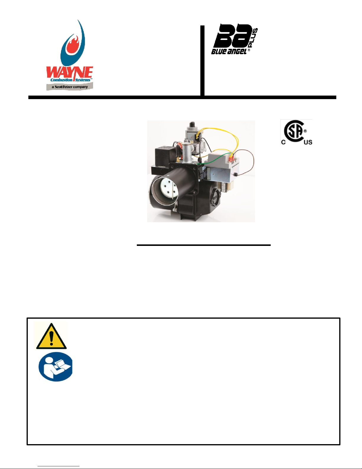
HSG200
HSG400
SPECIFICATIONS
BURNER MODELS MINIMUM INPUT MAXIMUM INPUT Air Tube Standard Lengths
HSG200 60,000 Btu/hr (18 kW) 200,000 Btu/hr (59 kW) 6, 9,12 in. (153, 229, 305 mm)
HSG400 200,000 Btu/hr (59 kW) 400,000 Btu/hr (117 kW) 6, 9,12 in. (159, 229, 305 mm)
FUELS: Natural Gas and LP Gas FLAME SAFETY: 24 Vac Electronic IGNITION: 7300 Vac Direct Spark
AVAILABLE VOLTAGES: 120 Vac 60 Hz, 230 Vac 50/60 Hz 1 Phase
AIR TUBE DIAMETER: 4 in (101.6 mm) MOUNTING: Adjustable Flange is standard; Pedestal Mount is Optional
Gas Burners
READ THIS MANUAL BEFORE USING THIS PRODUCT. FAILURE TO FOLLOW THE
INSTRUCTIONS AND SAFETY PRECAUTIONS IN THIS MANUAL CAN RESULT IN
SERIOUS INJURY OR DEATH. KEEP THIS MANUAL FOR FUTURE REFERENCE.
INSTALLTION OF THE BURNER MUST BE DONE BY A QUALIFIED INSTALLER IN
ACCORDANCE WITH REGULATIONS OF THE NATIONAL FUEL GAS CODE ANSI
Z223.1/NFPA54, AND IN COMPLETE ACCORDANCE WITH ALL LOCAL CODES AND
AUTHORITIES HAVING JURISDICTION.
A QUALIFIED INSTALLER IS THE PERSON WHO IS RESPONSIBLE FOR THE
INSTALLATION AND ADJUSTMENT OF THE EQUIPMENT AND WHO IS LICENSED
TO INSTALL GAS-BURNING EQUIPMENT IN ACCORDANCE WITH ALL CODES AND
ORDINANCES.
CSA CERTIFICATION:
189810-1154925
ANSI Z21.17
MASS G3-0903-67
Page 2
This is the safety alert symbol. It is used to alert you to potential personal injury
hazards. The meaning of this safety alert symbol is as follows: Attention! Become alert!
Your safety may be at risk. The message that appears next to the warning which can be
either written or pictorially presented. NEVER remove or tamper with the warning labels,
safety devices or guards fitted on the unit.
Wayne Combustion System is NOT responsible for any bodily injury and/or property
damage that may result from operation outside of the stated operating conditions for
which this unit was intended.
Indicates a hazardous situation, which, if not avoided, will result in
death or serious bodily injury.
Indicates a hazardous situation, which, if not avoided, could result in
death or serious bodily injury.
Indicates a hazardous situation, which, if not avoided may result in
minor or moderate bodily injury.
Indicates a situation that may result in equipment-related damage.
Overview of Safety Warning System and Your Responsibilities
The safety of you and others depends upon you thoroughly reading and understanding this manual. If you
have questions or do not understand the information presented in this manual, please call Wayne
Combustion System or see www.waynecombustion.com.
Hazard Definitions:
2
Page 3
Hazard Level
Pictogram
Type
Hazard Explanation
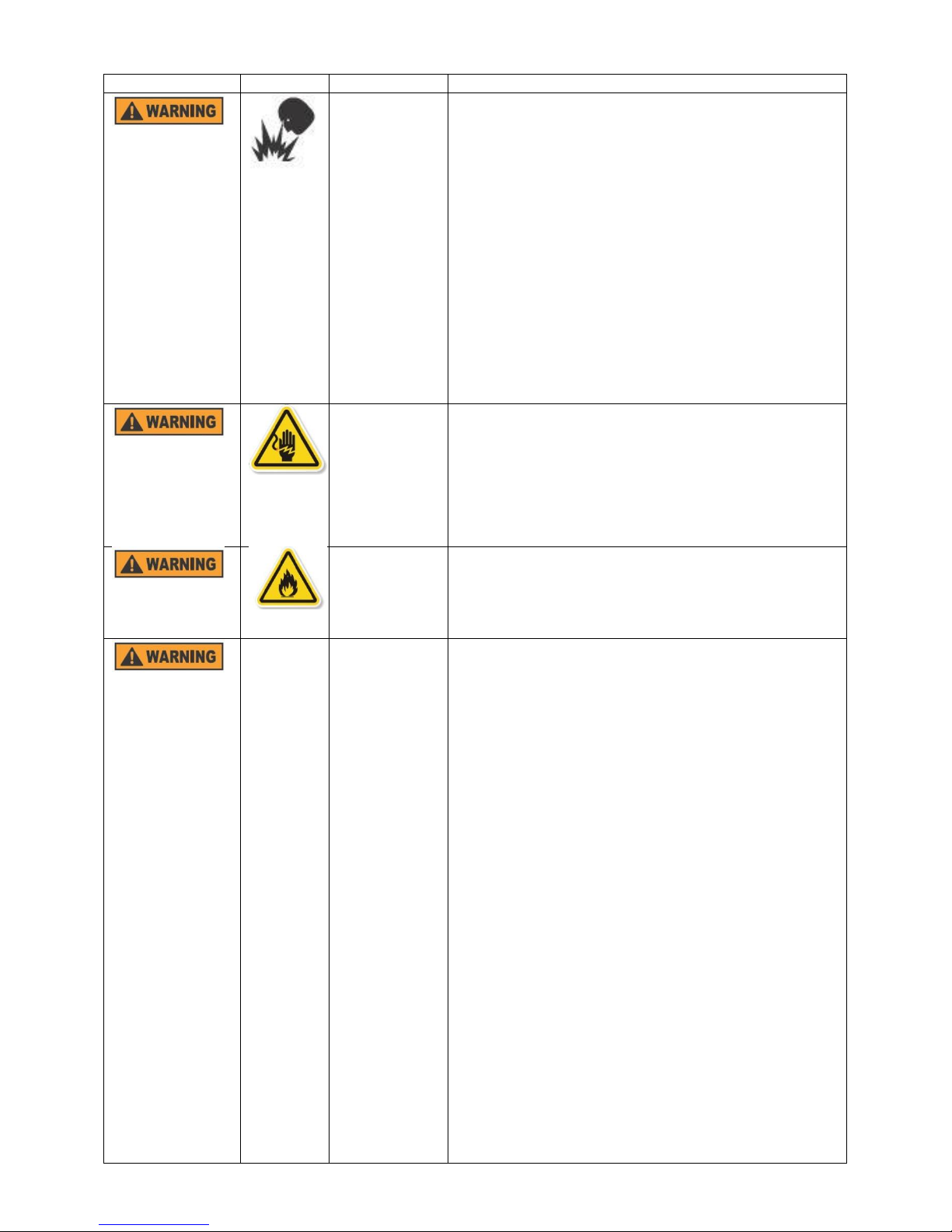
Fire or
Explosion
Failure to follow safety warnings exactly could
result in serious injury, death or property damage.
Do not store or use gasoline or other flammable
vapors and liquids in the vicinity of this or any
other appliance.
WHAT TO DO IF YOU SMELL GAS:
Open windows.
Do not try to light any appliances.
Do not touch electrical switches; do not use
any phone in your building.
Extinguish any open flame.
Immediately call your gas supplier from a
neighbor’s phone. Follow the gas supplier’s
instructions.
If you cannot reach your gas supplier, call the
fire department.
Electric shock
or burn
High voltages are present in this equipment. Follow
these rules to avoid electric shock:
Use only a properly grounded circuit. A ground
fault interrupter is recommended.
Do not spray water directly on burner.
Turn off power before servicing.
Read the owner’s manual before using.
Overheating
Should overheating occur:
Shut off the manual gas control to the
appliance.
DO NOT shut off power to the equipment,
allow blower to continue running.
Carbon
Monoxide
Poisoning
Carbon monoxide is a colorless, odorless gas that
can kill. Follow these rules to control carbon
monoxide:
Do not use this burner if in an unvented,
enclosed area. Carbon monoxide may
accumulate.
Do not adjust the pressure regulator. High
pressures produce carbon monoxide.
Check flue gases for carbon monoxide. This
check requires specialized equipment.
Allow only qualified burner service persons to
adjust the burner. Special instruments and
training are required.
Read the burner manual before using.
CARBON MONOXIDE POISONING: Early signs of
carbon monoxide poisoning are similar to the flu with
headaches, dizziness, weakness, nausea, vomiting,
sleepiness, and confusion. If you suspect carbon
monoxide poisoning, get outside to fresh air
immediately, and then call 911. Some people are more
affected by carbon monoxide than others. These
include pregnant women, people with heart or lung
disease or anemia, those under the influence of
alcohol, and those at high altitudes. Propane/LP gas
and natural gas are both odorless. An odor-making
agent is added to each of these gases. The odor helps
you detect a gas leak. However, the odor added to
these gases can fade. Gas may be present even
though no odor exists.
3
Page 4

Hazard Level
Pictogram
Type
Hazard Explanation
Proposition 65
material
This product can expose you to chemicals, including
lead, nickel, carbon monoxide and sulfur dioxide, which
are known to the State of California to cause cancer or
birth defects or other reproductive harm. For more
information, go to www.p65Warnings.ca.gov.
Special
Requirements
When contacting Wayne Combustion Systems for
service information, please have the burner
specification number and model number when calling
or writing. Specification number is at the bottom of the
“T” shape on the back of the burner and model number
is at the top of the “T” shape on the back of the burner.
If any instructions in the manual are not clear, contact Wayne
Combustion Systems at 1-260-425-9200 for assistance.
4
Page 5
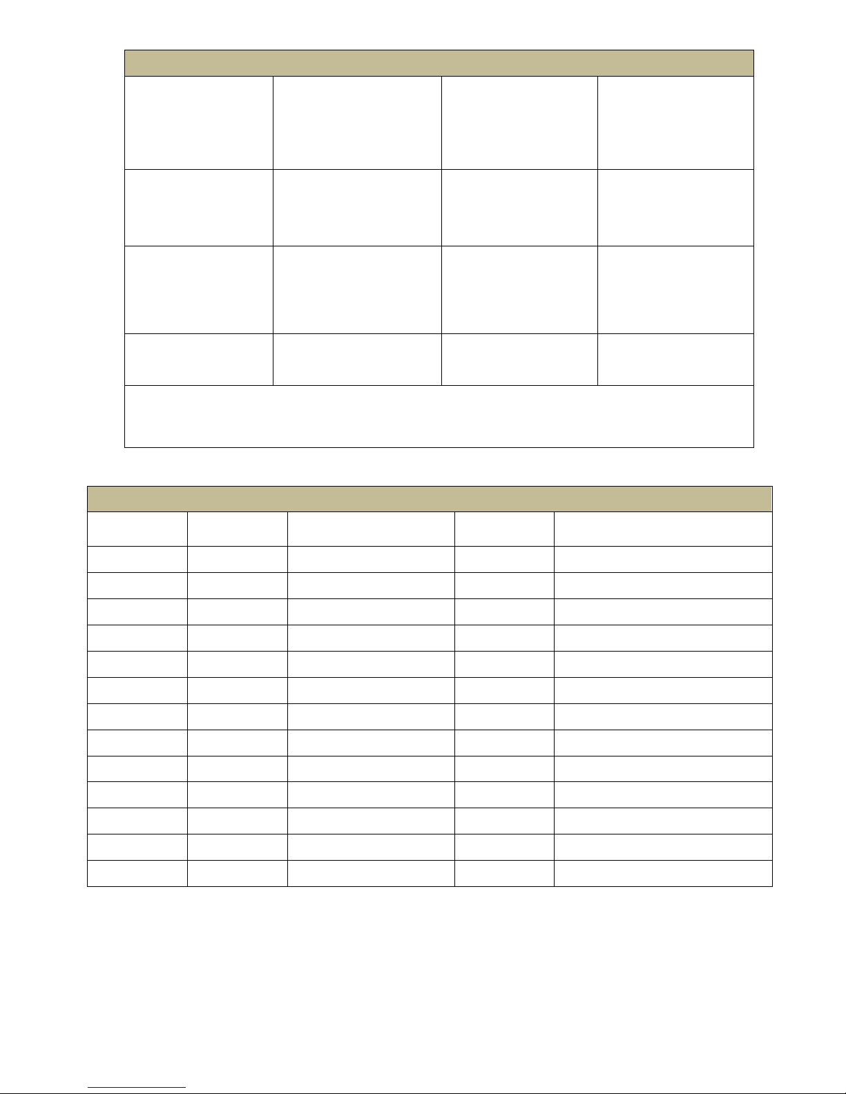
INSTALLATION LOG
BURNER MODEL:
SPECIFICATION
NUMBER:
FUEL (NATURAL OR
LP):
GAS ORIFICE SIZE:
INLET GAS
PRESSURE
(in. w.c.):
CO2 (%):
O2(%):
CO (PPM):
INSTALLER’S NAME:
CONTRACTOR NAME:
CONTRACTOR
ADDRESS:
CONTRACTOR PHONE
NUMBER:
CONTRACTOR
LICENSE #:
DATE OF INSTALLATION:
COMMENTS ABOUT INSTALLATION/START UP:
BURNER/APPLIANCE SERVICE LOG
SERVICE DATE
TECHNICIAN
COMPANY
/ ADDRESS
CONTRACTOR
LICENSE #
WORK PERFORMED
/ /
/ /
/ /
/ /
/ /
/ /
/ /
/ /
/ /
/ /
/ /
/ /
/ /
THESE INSTRUCTIONS SHOULD BE AFFIXED TO THE BURNER OR ADJACENT
TO THE HEATING APPLIANCE.
5
Page 6

Contents
SECTION I: INSTALLATION AND SETUP .......................................................................................................... 7
VISUAL INSPECTION OF THE HEATING SYSTEM .......................................................................................... 7
INSPECTION OF FLUE PIPE AND CHIMNEY .................................................................................................. 8
INSPECTION OF HEATING APPLIANCE ......................................................................................................... 9
FLUE PIPE, DRAFT HOOD, AND BAROMETERIC DAMPER ............................................................................ 9
PREPARATION OF COMBUSTION CHAMBER ............................................................................................. 11
SIZING OF COMBUSTION CHAMBER ......................................................................................................... 12
BURNER INSTALLATION ............................................................................................................................ 12
INSTALLATION OF MOUNTING FLANGE .................................................................................................... 12
DETERMINE ORIFICE SIZE AND RATE ........................................................................................................ 13
CHANGING THE ORIFICE ........................................................................................................................... 15
INSPECTION AND SIZING OF GAS PIPING .................................................................................................. 17
TESTING PIPING FOR LEAKS ...................................................................................................................... 20
ELECTRICAL WIRING OF BURNER .............................................................................................................. 20
INSPECTION OF LIMIT CONTROL SWITCHES ............................................................................................. 21
INSTALLATION OF THERMOSTAT .............................................................................................................. 21
SECTION II: INITIAL START UP ..................................................................................................................... 22
INITIAL BURNER START UP PROCEDURE ................................................................................................... 23
COMBUSTION ADJUSTMENT OF BURNER ................................................................................................. 24
SECTION III: GAS CONVERSION ................................................................................................................... 25
SECTION IV: CONSUMER INSTRUCTIONS .................................................................................................... 26
GENERAL INSTRUCTIONS FOR SERVICING BURNER .................................................................................. 26
SECTION V: SERVICE AND TROUBLESHOOTING .......................................................................................... 27
HSG SERIES BURNER UTILIZING WAYNE 64420 SERIES IGNITION CONTROLS .......................................... 27
HSG SERIES BURNER UTILIZING HONEYWELL IGNITION CONTROLS ........................................................ 28
FLAME SENSING ON HSG SERIES BURNERS .............................................................................................. 29
TROUBLESHOOTING GUIDE PRIMARY IGNITION CONTROLS .................................................................... 32
SERVICING HSG SERIES BURNER ............................................................................................................... 38
TROUBLESHOOTING GUIDE ...................................................................................................................... 40
HSG WIRING DIAGRAMS ........................................................................................................................... 42
SECTION VI: PARTS LIST AND EXPLODED VIEWS ......................................................................................... 46
HSG200/400 PARTS LIST ........................................................................................................................... 46
HSG EXPLODED VIEWS .............................................................................................................................. 47
SECTION VII: WARRANTY ............................................................................................................................ 51
6
Page 7
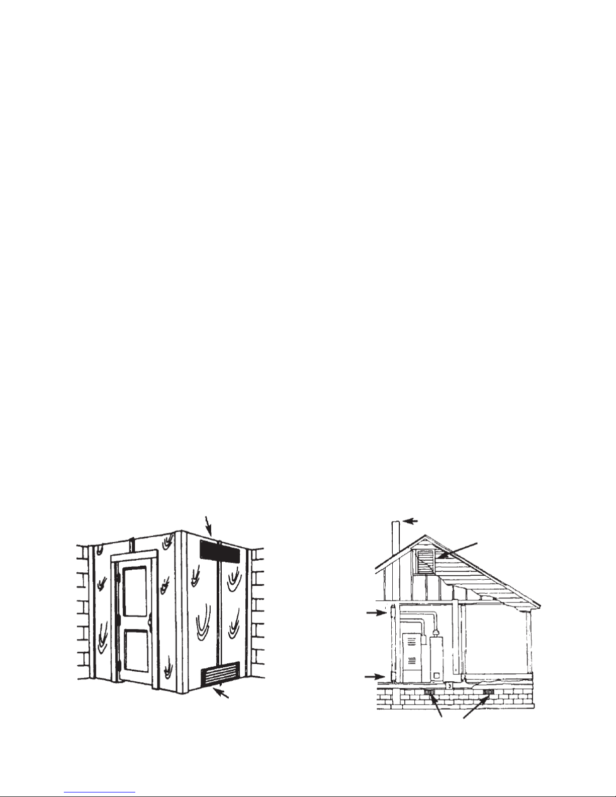
Ventilating Air Opening
1 Sq. in. (645.2 mm2)
for each 1,000 Btu
(.29 kW) per hour
Input, 100 Sq. in. minimum.
Application below located in confined spaces. Ventilation
air from inside building – combustion and draft hood
dilution air from outside with ventilated attic or ventilated
crawl space.
3. CHIMNEY OR GAS
2. ATTIC
VENTILATION
LOUVERS
VENTILATION
AIR OUTLET
1. VENTILATION
AIR INLET
Air Inlet Opening 1 Sq. in.
(645.2 mm2) for each
1,000 Btu (.29 kW)
per hour input, 100 Sq. in.
minimum.
CRAWL SPACE VENTILATION LOUVERS
Illustration above shows air opening
necessary to supply air for combustion
when heating appliance is installed in
an enclosed room.
Figure 1
Figure 2
SECTION I: INSTALLATION AND SETUP
These instructions were prepared for the guidance of those installing this particular gas conversion burner.
While they apply in principle to all installations, they should not be interpreted as meaning the only safe and
economical way to install a conversion burner. It may be necessary to deviate from these instructions in some
instances in order to comply with local gas company rules or codes in effect in the area in which the installation is
made. It is recommended that the installer confer with the local gas company and with the proper municipal officials
regarding any specific code or regulation governing the installation of gas conversion burners.
The installation must conform with local codes or, in the absence of local codes, with the American National Standard
ANSI Z21.8 Installation of Domestic Gas Conversion Burners and ANSI Z223.1 the National Fuel Gas Code, latest
version.
Safe and economical operation of the burner throughout its service life is dependent to a large extent upon its
proper installation in the heating appliance. Therefore, we may impress upon the installer that good clean workmanlike
installations mean satisfied customers.
VISUAL INSPECTION OF THE HEATING SYSTEM
A conversion burner shall not be installed in an appliance located in a room or basement where facilities for normal air
circulation or infiltration are so limited so as to interfere with ready obtainment of all air necessary for proper
combustion and draft hood dilution, unless at the time of burner installation special provisions are made for combustion
and draft hood dilution air.
a. In open basements of homes of normal construction (without basement storm windows or tight stair doors)
infiltration of combustion air is usually sufficient to replace that drawn up the flue, so special provisions are
seldom necessary.
b. When the heating appliance is installed in a tightly closed room without ventilating openings to outdoors or
other rooms, provisions shall be made for supplying air for combustion through special openings, one near
the floor line and the other near the ceiling, each to be sized on the basis of one square inch or more of free
area for each 1,000 Btu/hr (0.2931 kW) input but not less than 100 square inches. (See Figure 1).
c. When the house is of unusually tight construction, has a (kitchen) ventilating fan which may be used for
exhausting air from indoors, or has a vented fireplace, it is recommended that combustion air be supplied to
the furnace room through intakes extending to the outside of the building and terminating in down turned
fittings, suitably arranged to prevent obstruction from snow or rain, and including a protecting screen not
smaller than 1/4-inch (6.35 mm) mesh.
7
Page 8

NOTE ON FIGURE 2: Ducts used for make-up air may be connected to the cold air return of the heating system only if
they connect directly to outdoor air. Attic Ventilation Louvers are required at each end of attic with alternate air inlet
No. 1.
1, 2, and 3 mark alternate locations for air from outdoors. Free area shall be not less than 1 sq.in. (645.2 mm2) per
5,000 Btu/hr (1.465 kW) of the total input rating of all appliances in the enclosure.
Crawl-space Ventilation Louvers for unheated crawl space are required with alternate air inlet No. 3.
Each Ventilation Air Opening from inside the building shall have a free area of not less than 1 sq. in. (645.2 mm2) per
5,000 Btu per hour (1.465 kW) of the total input rating of all appliances in the enclosure.
The heating system (both the heat exchanger and distribution system) shall be of a size to properly heat the
building. Through inquiry it shall be determined that all rooms have been heated adequately without wide
variations in temperature, without objectionable drafts, and without excessive fuel costs in the past. If the heating
system is deficient with respect to any of the above determinations, provisions shall be made to correct the
deficiency, replace obsolete parts, or (by installing storm windows, insulation, etc.) to reduce the heat loss to a
point where the existing system will provide the proper amount of heat.
a. Gravity Warm Air System
The supply and return ducts and registers should be sized and arranged so that the house can be heated
without excessive furnace temperatures. Reference may be made to the American Society of Heating,
Refrigerating and Air-Conditioning Engineers Guide and Data Book series and Handbook of Fundamentals.*
b. Forced Warm Air Systems
Inspection should also show whether the electrical characteristics of the fan and limit switch are satisfactory
and whether the air filters and fan are in condition for continued proper service with the gas burner.
Reference may be made to the American Society of Heating, Refrigerating and Air-Conditioning Engineers
Guide and Data Book series and Handbook of Fundamentals.*
c. Hot Water Systems
The boiler thermometer and altitude gauge should be in good order. On a closed system, the feed and
pressure relief valves shall be in proper operating condition. If there is an expansion tank on a closed system,
inspection should show it to be substantially empty of water. When there is an existing water temperature
limiting switch, its operating and electrical characteristics shall be checked to determine its suitability to the
gas control circuit. For common piping systems reference can be made to the American Society of Heating,
Refrigerating and Air-Conditioning Engineers Guide and Data Book series* and to the Hydronic Institute
I=B=R Guides.**
d. Steam or Vapor System
The system shall be pressure tight, with pressure gauge and pop safety valve in good condition and with an
existing water glass which permits clear observation of boiler water level. When there is a pressure limit
switch or low-water cut-off, inspection shall determine whether either device can be utilized in the gas burner
control circuit, reference should be made to the American Society of Heating, Refrigerating and Air-
Conditioning Engineers and Institute of Boiler and Radiator Manufacturers guides. Traps and air vents shall
be of adequate capacity, in good condition, and correctly placed in the system.
*Copies may be obtained from the http://www.ashrae.org
**Copies may be obtained from the Hydronic Institute, 35 Russo Place, Berkeley, NJ 07922.
INSPECTION OF FLUE PIPE AND CHIMNEY
The flue pipe should be carefully inspected and replaced if necessary in connection with installation of a draft
hood. A barometric damper may be used per Flue Pipe, Draft Hood, and Barometric Damper section of
manual. All installations must operate with a negative draft overfire. Refer to your local gas company or
codes for assistance or to the furnace and/or boiler manufacturer for recommendations.
The flue pipe entrance into the chimney should be at least two feet (0.610m) above the clean-out opening in
the chimney.
The chimney should extend high enough above the dwelling or other neighboring obstructions so that wind
from any direction will not strike the chimney from any angle above horizontal. Unless the obstruction is of
greater magnitude, it is the usual experience that a chimney extending two feet above flat roofs or above fire
wall parapets, and peaked roofs within 30 feet (9.144m) will be reasonably free of downdraft.
8
Page 9
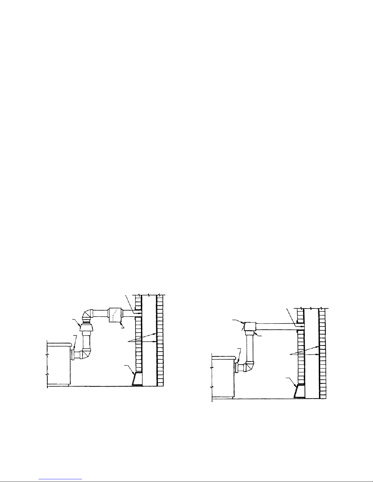
Pitch Horizontal Run
1/4” (6.35mm) MIN.
per foot (0.305m)
Do Not Extend Flue
Pipe Beyond Inside
of Chimney
Cleanout
Reducer
Corrosion
Resistant Lining
Bull Head Tee
Single Acting
Control
Do Not Extend Flue
of Chimney
Pitch Horizontal Run
per foot (0.305m)
Vertical Draft Hood
Reducer
Horizontal
Draft Hood
Corrosion
Resistant Lining
Select either
Horizontal or
Vertical Draft Hood
Cleanout
Draft Hood Positions
Figure 3
Barometric Draft Control
Position
Figure 4
Where the chimney is unlined or where local experience indicates that flue gas condensate might be a
problem, the local gas company should be consulted.
The chimney should be examined and thoroughly cleaned, if necessary, before installation is made to make
sure it will freely conduct the flue gases to the outside.
Flue pipe should extend through the chimney wall to the inner face of the chimney liner but not beyond, and
should be firmly cemented to masonry. A thimble may be used to facilitate removal of flue pipe for cleaning, in
which event the thimble should be permanently cemented in place with mortar or other fireproof material that
will not crack or check the flue pipe or thimble, whichever is used, should be sealed into the chimney liner.
Flue connections from two or more appliances should not enter opposing or adjacent sides of the chimney at
the same level.
Under no circumstances should the flue pipe be connected to a flue of an open fireplace.
INSPECTION OF HEATING APPLIANCE
Clean the appliance heat exchanger interior, combustion chamber and flue connections. Remove all adhering
tars, scale, dirt, and soot. Inspect the heat exchanger for obvious and potential flue gas leaks. Cement all joints
around the appliance base and access openings to prevent air and/or flue gas leakage into or out of the
combustion chamber.
Warm Air Furnaces* - Make certain the electrical characteristics of the fan and limit switch correspond to those
required by this burner and that they are in proper working order.
Hot Water Boilers* - Make certain water temperature and altitude gauges, pressure relief valves are in proper
working order.
Steam Boilers* - Make certain the system is pressure tight and that the pressure gage and pop off safety valve are
in proper working order. Verify existing water sight glass permits clear observation of boiler water level.
*Where applicable, existing temperature of pressure limit switch or low water cut-off switch operation and
electrical characteristics shall be checked to determine their compatibility to the gas control circuitry of this burner.
NOTE: For oil fired conversions consult boiler or furnace manufacturer. Appliance must maintain negative draft over
fire.
FLUE PIPE, DRAFT HOOD, AND BAROMETERIC DAMPER
1/4” (6.35mm) MIN.
Pipe Beyond Inside
Barometric Draft
9
Page 10

Input Btu/hr (kW)
Drafthood Flue Pipe Size
Up to 120,000 Btu/hr (35 kW)
5 Inch (127 mm) Diameter
120,000 Btu/hr (35 kW) – 180,000 Btu/hr (53 kW)
6 Inch (152 mm) Diameter
180,000 Btu/hr (53 kW) – 250,000 Btu/hr (73 kW)
7 Inch (178 mm) Diameter
250,000 Btu/hr (73 kW) – 320,000 Btu/hr (94 kW)
8 Inch (203 mm) Diameter
320,000 Btu/hr (94 kW) – 410,000 Btu/hr (120 kW)
9 Inch (229 mm) Diameter
Strict compliance to appropriate codes should be made regarding flue pipe clearances from combustible
materials. A CSA type draft hood or its equivalent shall be placed in and made part of the flue pipe from
the appliance. A barometric damper may be used in place of the draft hood where permitted by local
building codes. If an oil barometric damper has been previously installed this may be used if it is in good
condition and any and all weights and/or stops are removed. The flapper on a gas barometric damper must
be free swinging in both directions. Check with local building codes and building inspectors. At no time
should the draft hood be located at a point lower than the highest flue passage in the appliance. The draft
hood should be installed in the position for which it was designed and in no case installed in a false ceiling,
separate room from the heating appliance, or in any other manner that will permit a difference in pressure
between the draft hood relief opening and the combustion air supply. On sealed type appliances where all
combustion air is taken from the outside, a cap should be installed on end of flue pipe to prevent back
drafts. In such cases no draft hood or diverter should be installed inside.
Pitch the horizontal run of the flue pipe upward 1/4 inch (6.35 mm) per foot (0.305 m) or more. Run directly
to the chimney, fasten joints securely and support horizontal runs to prevent snagging. If the flue pipe must
be extra-long, it’s size should be increased. The horizontal length of the flue pipe should not exceed the
height of the chimney above the flue connection.
The draft control should be hood type per Figure 3 or, IF APPROVED BY LOCAL AUTHORITIES, a single
barometric damper suitable for gas firing per Figure 4. The draft control should be sized the same as the
flue pipe per Figure 5. Refer to the barometric draft regulator manufacturer’s instructions for complete
detail.
NOTICE: Should the flue pass through a partition the draft control must be located in the same room as
the heating appliance.
DRAFT HOOD & FLUE PIPE SIZES FOR GAS CONVERSION BURNERS IN FURNACES AND BOILERS
Figure 5
NOTE: If the flue pipe exceeds 10 ft. (3 m) in length, or contains more than two elbows, use next size larger
pipe and draft hood.
NOTE: All installations must operate with negative draft over fire. Refer to your local gas company and codes
for assistance.
When installing the burner in revertible flue (down draft or diving flue type) furnaces or boilers, the draft hood (or
draft diverter) should be located at least one foot higher than the top of the highest point of the appliance flue
passage or combustion chamber. It is also recommended that a vent pipe, not less than one inch in diameter, be
provided from the highest point in the flue passage, directly to the flue pipe. This is not necessary on the
appliances with built in up draft bypass. The gas company serving the area should be consulted in regards to their
recommendations for converting this type of furnace or boiler.
The flue pipe should be securely supported and the joints fastened with sheet metal screws or riveted to prevent
sagging, and in no case should be located in a manner that will present a hazard to combustible building material.
(Refer to local building code).
10
Page 11
Forced Air Furnace
Figure 6
Hot Water or Steam Boiler
with Combustion Chamber
Target
Figure 7
Hot Water or Steam Boiler
with Combustion Chamber
Liner
Figure 8
HSG
Burner
HSG
Burner
HSG
Burner
Mounting
Flange
Mounting Flange
Mounting Flange
To Protect Properly
Locate End of Burner Tube. Position Tube
1/8” (3.2 mm) Short of Inside of
Combustion Chamber
To Protect Properly
Locate End of
Burner Tube.
Position Tube 1/8”
(3.2 mm) Short of
Inside of
Combustion
Chamber
To Protect Properly
Locate End of
Burner Tube.
Position Tube 1/8”
(3.2 mm) Short of
Inside of
Combustion
Chamber
Existing
Prefabricated
Combustion
Chamber
Liner
Existing
Prefabricated
Combustion
Chamber
Liner
Existing
Prefabricated
Combustion
Chamber
Liner
PREPARATION OF COMBUSTION CHAMBER
Clean the combustion chamber thoroughly. Scrape and brush all heating surfaces and flue ways. Soot and fly ash are
excellent insulators and unless removed, the efficiency of the heating appliance will be impaired. Plugged or restricted
flue passages will prevent burner from operating properly.
Be sure water column and gauge on boiler are clean and water level is visible. In all cases make sure the pigtail to limit
control is clear. Safety pop valves on steam boilers and automatic relief valves on closed water systems should be
thoroughly checked to make sure they are in good working condition.
When converting oil designed boilers and furnaces, it is recommended that the existing combustion chamber be used
with the gas burner, provided it is in good condition. If the blast tube opening into the combustion chamber is larger
than the 4” (102 mm) diameter, high temperature cement should be used to reduce the opening to 4” (102 mm)
diameter.
IN NO CASE SHOULD THE TUBE BE ALLOWED TO EXTEND INTO THE CHAMBER PROPER. IT MUST BE AT
LEAST 1/8” (3.2mm) SHORT OF THE INSIDE SURFACE OF THE COMBUSTION CHAMBER. (SEE FIGURES 6, 7,
8)
11
Page 12

Input
Btu/hr (kW)
Preferred
Width Inches (mm) x
Length Inches (mm)
Diameter
Inches (mm)
50,000 (14.7)
7 (177.8) x 7 (177.8)
8 (203)
75,000 (22.0)
7.5 (190.5) x 7.5 (190.5)
9 (229)
100,000 (29.3)
12 (304.8) x 12 (304.8)
13 (330)
150,000 (44.0)
12 (304.8) x 15 (381)
14 (356)
200,000 (58.6)
13 (330.2) x 17 (431.8)
15 (381)
250,000 (73.3)
13 (330.2) x 18 (457.2)
16 (406)
300,000 (88.0)
13 (330.2) x 20 (508)
18 (457)
350,000 (102.6)
14 (355.6) x 21 (533.4)
20 (508)
400,000 (117.2)
15 (381) x 22 (558.8)
21 (533)
Recommended Combustion Chamber Sizes
Figure 9
SIZING OF COMBUSTION CHAMBER
The following table is provided as a guideline for determining combustion chamber size and corresponding
firing rate when appliance rates are not available.
BURNER INSTALLATION
The HSG200 and HSG400 power gas burners were designed for converting oil fired furnaces and boilers. Due
consideration was given to making it as simple and easy to install and service as possible without weakening its
durability or efficiency. The burner is supplied as a completely assembled package unit.
NOTE: The burner must be installed in such a manner that all controls will be readily accessible for inspection,
cleaning, adjustment and repairs.
INSTALLATION OF MOUNTING FLANGE
Position the mounting flange on the furnace wall, adjusting orientation as necessary until the bolt pattern of the furnace
allows the flange to sit flush. (See Figure 10 for flange dimensions.)
Note the orientation of the flange and remove it so that the flange gasket may be placed between the furnace wall and
the flange. Tighten the flange to the furnace wall.
Insert the burner tube into the flange and position it per Figures 6, 7, 8. Tighten the flange onto the burner tube.
12
Page 13
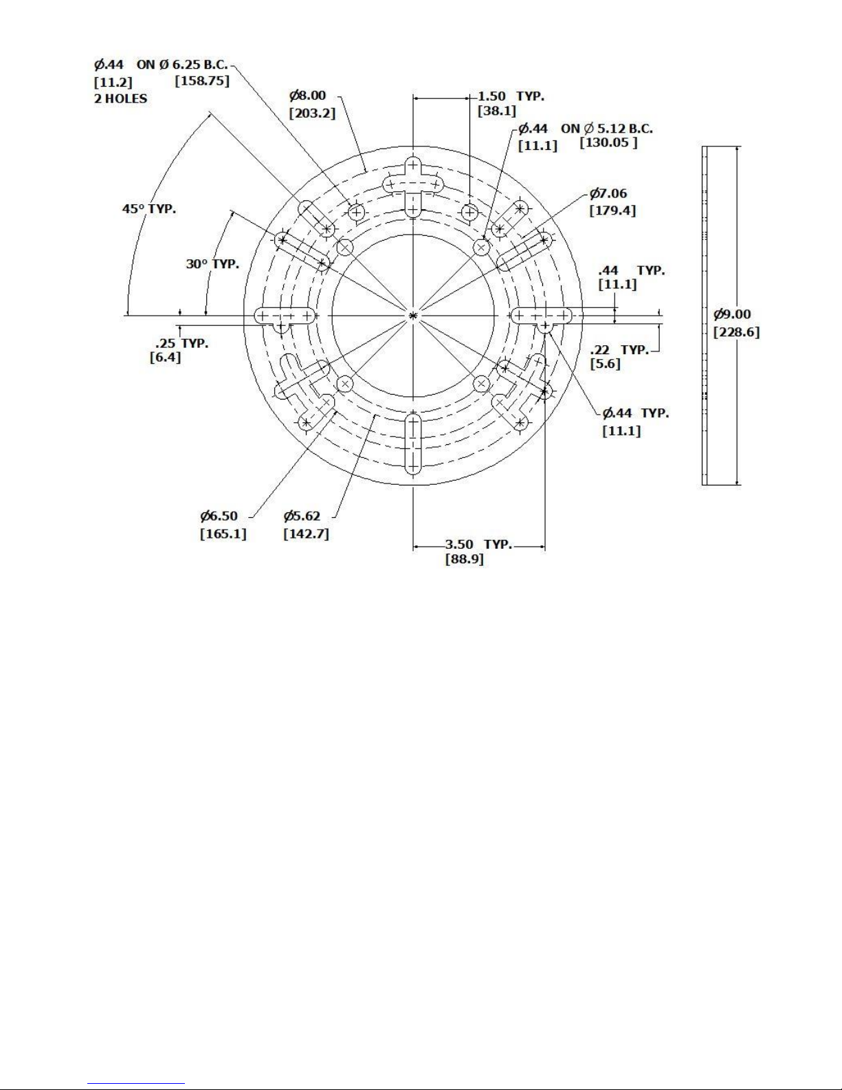
FIGURE 10: Adjustable Mounting Flange Dimensions
DETERMINE ORIFICE SIZE AND RATE
The gas conversion burner needs to be set to deliver the same amount of heat to the appliance as the oil burner it is
replacing. Determine the Btu/hr heat input rate for the appliance by locating the rating plate of the appliance and
determine the firing rate of the oil burner. Typically the nozzle in the oil burner is stamped with the gallon per hour rate.
Use the lesser of these two rates as the firing rate of the gas burner.
For calculating from gallon/hour of oil to Btu/hour of gas, one gallon of oil produces 140,000 Btu/gal (147700 kJ/L) of
heat. For example: A furnace rating of 0.60 G.P.H. would be 0.60 x 140,000 = 84,000 Btu/hr. This is the input rate
needed from the gas burner.
Once the desired heat output of the burner has been determined, the gas orifice must be properly sized. The HSG200
and HSG400 power gas conversion burners are approved for use with natural and LP gas only. The HSG200 and
HSG400 burner models are shipped labeled and orificed for natural gas. To convert to LP gas and/or increase Btu/hr
(kW) input on natural or LP gas, an orifice kit is supplied with each burner with the orifices shown in Figure 11. Use
Figure 11 to select orifice size and manifold pressure to achieve desired rate on burner. If the desired input rating
cannot be obtained within the Figure 11 manifold orifice pressure adjustment range, the next size larger or smaller
orifice should be used (Refer to orifice chart Figure 11).
HSG200 is shipped from factory with a #8 - 0.199” orifice installed and HSG400 is shipped from the factory with a T -
0.358” orifice. The combination gas valve pressure regulator, which has an outlet pressure setting range of
approximately 2.0” w.c. (498.2 Pa) to 4.0” w.c (996.4 Pa) and is factory set at 3.5” w.c. (872 Pa).
13
Page 14
Orifice Size and Drill
Manifold Pressure
2.0” (498 Pa)
3.0” (747 Pa)
4.0” (996 Pa)
HSG200 Natural Gas
#29 -.136 (3.5 mm)
50,000 (15)
64,000 (19)
76,500 (22)
#8 - .199 (5.1mm)
74,000 (22)
95,000 (28)
116,000 (34)
J - .277 (7.0 mm)
112,000 (33)
138,000 (40)
164,000 (48)
Q - .332 (8.4 mm)
160,000 (47)
206,000 (60)
-
HSG200 LP Gas
#30 - .128 (3.3 mm)
49,000 (14)
58,500 (17)
68,200 (20)
#27 - .144 (3.7 mm)
66,000 (19)
78,000 (23)
92,000 (27)
#15 - .180 (4.6 mm)
82,000 (24)
112,500 (33)
136,000 (40)
D - .246 (6.2 mm)
131,000 (38)
187,500 (55)
243,000 (71)
HSG400 Natural Gas
T - .358 (9.1 mm)
200,000 (59)
248,000 (73)
285,000 (84)
15/32 - .468 (11.9 mm)
265,000 (78)
343,000 (101)
400,000 (117)
HSG400 LP Gas
K - .281 (7.1 mm)
190,000 (56)
242,500 (71)
295,000 (86)
Q - .332 (8.4 mm)
242,500 (71)
332,500 (97)
400,000 (117)
GAS LEAK HAZARD
Liquefied petroleum gas is heavier than air. All connections should be checked for
leaks using a soapy solution applied to gas connections. Leaking gas will settle in
low lying areas such as basements and trenches. This can lead to asphyxiation and
explosion.
Valve is rated for 0.5 PSI or 14 inch w.c. Over pressurizing valve
may cause damage to the valve.
HSG SERIES POWER GAS CONVERION BURNER ORIFICE CHART
Figure 11: Orifice Selection Guide
NOTE: For 50 cycle application de-rate input by 15%
NOTE: The Btu/hr input values in Figure 11 show the approximate hourly input of the burner for the various orifice
sizes. To determine the actual input of the burner by using the gas meter, follow these steps:
1) Turn off all other gas appliances.
2) The hand on the dial with the lowest cubic feet value (fastest revolving dial) should be clocked for one complete
revolution.
3) Divide 3,600 by the time in seconds for one complete revolution and multiply by the dial value (1, 2, or 5 cubic feet
depending on size of meter.)
4) Multiply this by the heating value of the gas to obtain the input to the burner in Btu per hour.
EXAMPLE: Time in seconds for one complete revolution of dial is 72. 3,600 divided by 72 is 50, 2 cubic foot was timed
therefore 50 x 2 is 100. Multiply 100 by heating value of gas which is 1,075 for natural gas; and this will give you an
input of 107,500 Btu/hr (31.51 kW). Use a heating value of 2500 for LP gas.
Running Pressure Required: Natural or LP 5.5” w.c. (1400 Pa) Minimum, 14” w.c. (3500 Pa) Maximum.
De-rate input for altitude over 2000 ft. (609.6 m) by 4% each 1000 ft. (304.8 m) above sea level.
IMPORTANT: MANIFOLD PRESSURE ADJUSTMENTS CAN ONLY BE MADE WITH THE BURNER
RUNNING AND THE GAS ON.
14
Page 15
CHANGING THE ORIFICE
Before replacing the orifice, the gas supply and power must be shut off. The HSG200 is shipped from
factory with a #8 - 0.199” orifice installed and HSG400 is shipped from the factory with a T - 0.358” orifice
installed. The combination gas valve pressure regulator, which has an outlet pressure setting range of
approximately 2.0” w.c. (498.2 Pa) to 4.0” w.c (996.4 Pa) is factory set at 3.5” w.c. (871.85 Pa). The HSG
Series burners come with an orifice kit that contains all the size orifices listed in Figure 11.
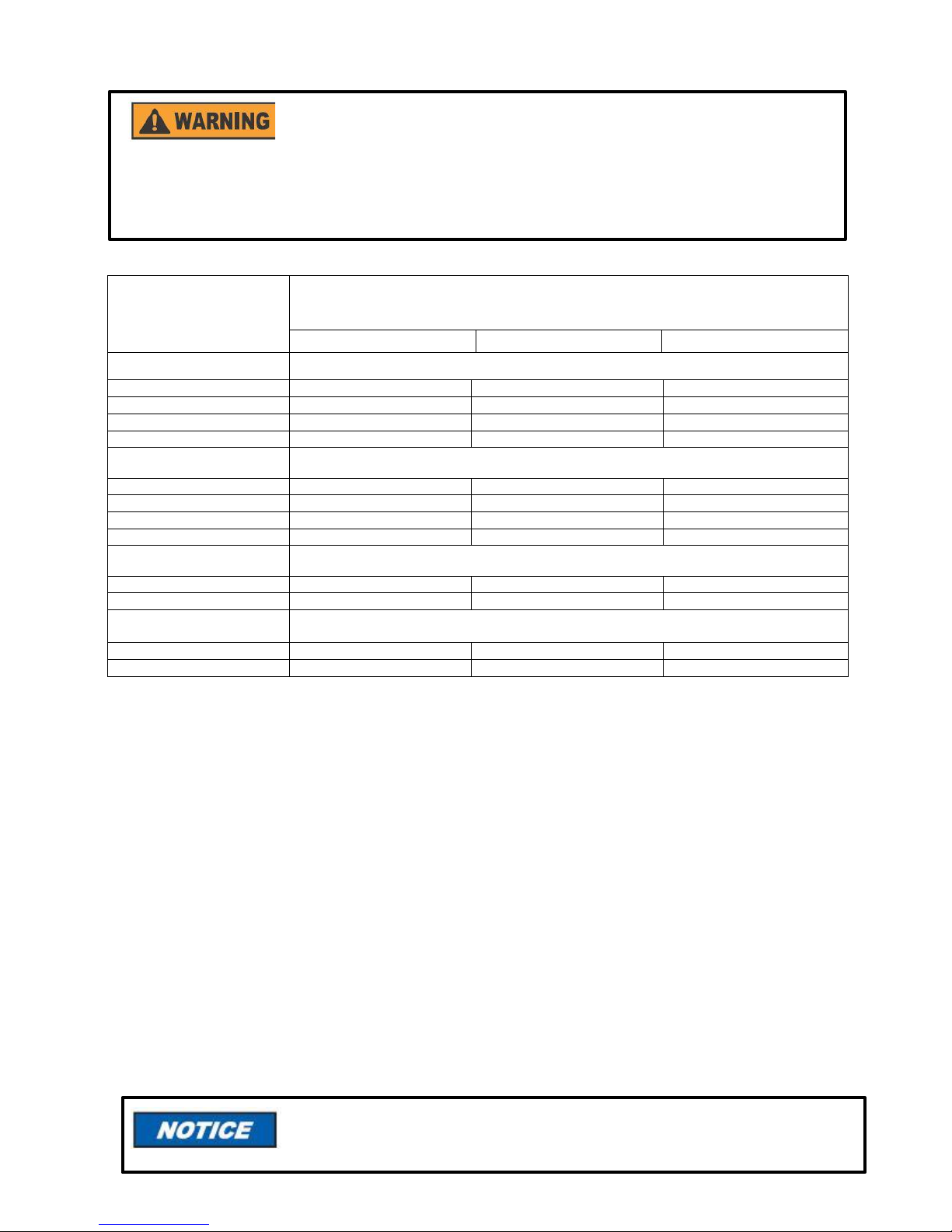
To remove the orifice, locate the HSG manifold (Figure 12).
Figure 12: HSG Manifold
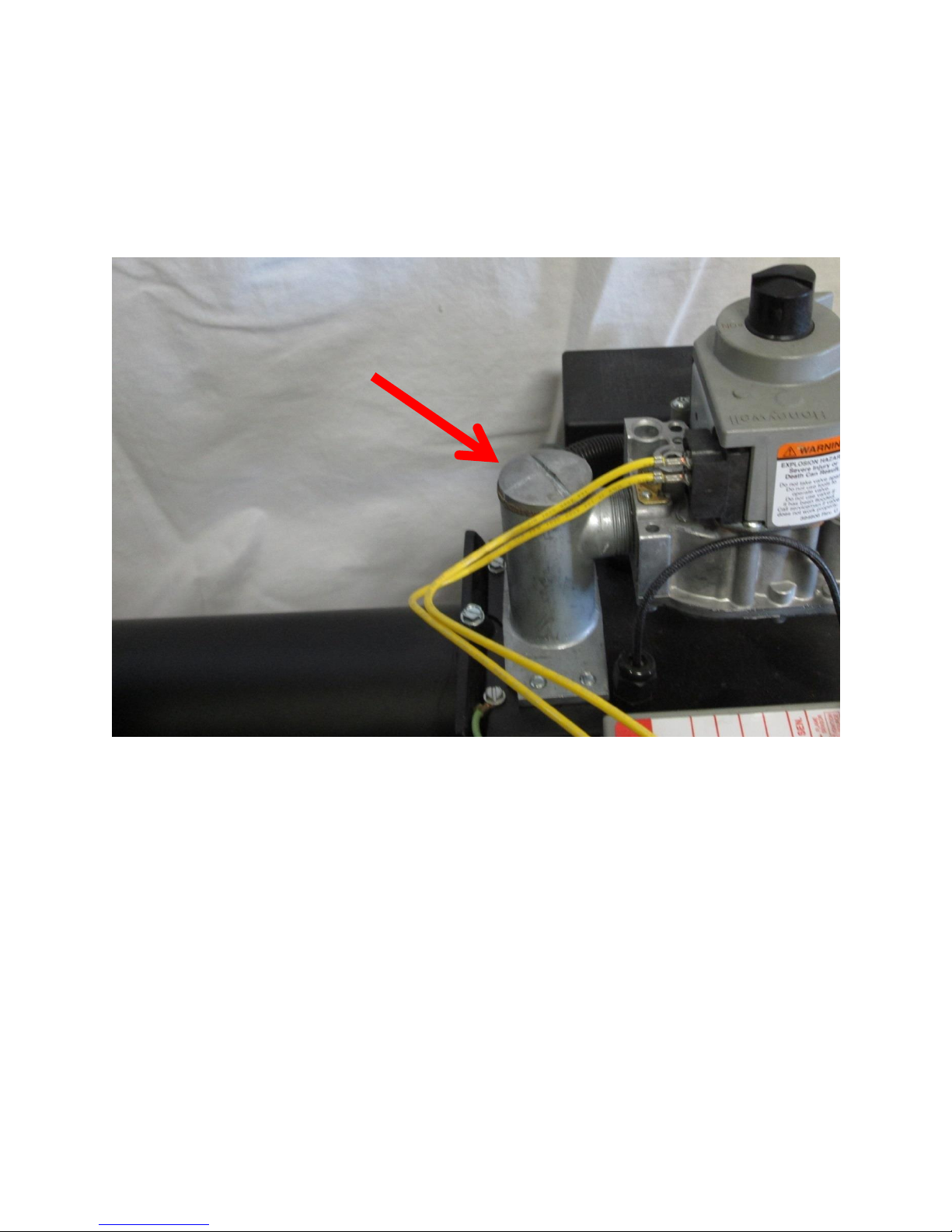
Once the HSG manifold is located, remove the slotted orifice cap, making sure the orifice cap gasket stays
attached to the orifice cap and is not damaged (Figure 13).
15
Page 16
GASKET
ORIFICE
CAP
Figure 13: HSG Cap with Gasket on Manifold
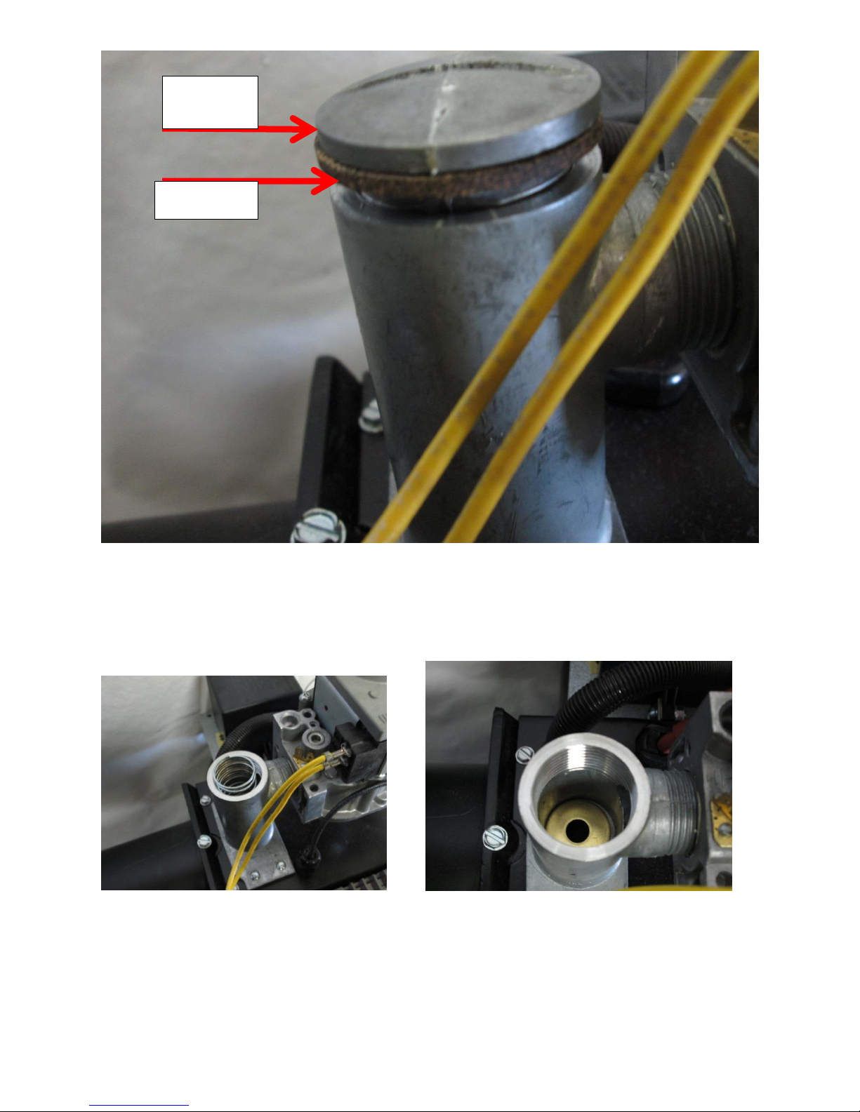
Remove orifice spring to access and remove orifice (Figure 14). Orifice will be stamped with its size
(Figure 15).
Figure 14: HSG Cap with Gasket Removed and Spring Removed
16
Page 17

All piping must comply with local codes and ordinances or the
National Fuel Gas Code ANSI Z223.1/NFPA No. 54.
Figure 15: HSG Orifice
Install the new orifice in manifold, reinstall spring and cap with gasket in the manifold. The orifice kit
included with conversion burners also contains gas identification labels. When changing from one gas to
another, locate the gas identification label on the burner and if necessary, place the proper label from the
kit over the label on the burner. The burner is now ready to be connected to the gas supply piping; see
instructions in next section.
INSPECTION AND SIZING OF GAS PIPING
A sediment trap or drip leg must be installed in the supply line to the burner. A union shall be installed in
the gas line upstream from the control manifold and downstream from the sediment trap or drip leg (See
Figure 16). A 1/8” NPT plugged tapping port accessible for test gauge connection shall be installed
immediately upstream of the gas supply connection for the purpose of determining the gas supply pressure
to the burner. A manual shutoff valve shall be installed in the gas supply line external to the appliance (See
Figure 16). If the gas supply pressure exceeds the 14” w.c. (3.5 kPa) maximum, an intermediate main
gas regulator must be installed ahead of the main gas manual shutoff valve shown in Figure 16.
17
Page 18

Supply Line Connection to Burner
Figure 16
Drip Leg
3’’ MIN
(76.2 mm)
Control Manifold
Union
Tee
Direction
of Flow
Pipe Cap
Manual Shutoff
Valve
1/8” (3.175mm) N.P.T.
The gas line should be a separate supply direct from the meter to the burner. It is recommended that new
pipe be used and located so that a minimum amount of work will be required in future servicing. The piping
should be so installed as to be durable, substantial and gas tight. It should be clear and free from cutting
burrs and defects in structure or threading. Aluminum tubing should not be used for the main gas supply.
Joint compounds (pipe dope) should be used sparingly on male threads only and be approved for all
gases.
It is recommended that tables 1, 2, and 3 be used to determine the size pipe to use from the meter to the
burner. The building structure should not be weakened by installation for the gas piping. The piping should
not be supported by the other piping, but should be firmly supported with pipe hooks, straps, bands or
hangers. Butt or lap welded pipe should not be bent. Note: Each elbow, union, and tee adds
approximately 2.5 feet of pipe.
The gas piping should be so installed so as to prevent an accumulation of condensation and it must be
protected against freezing. A horizontal pipe should be pitched so that it grades toward the meter and is
free from sags. The pipe should not be run through or in an air duct or clothes chute. The appliance and its
individual shutoff valve must be disconnected from the gas supply piping system during any pressure
testing of the system at test pressure in excess of 1/2 psig (3447 PaG). The appliance must be isolated
from the gas supply piping system by closing its individual manual shutoff valve during any pressure
testing of the gas supply piping system at test pressures equal to or less than 1/2 psig (3447 PaG).
Plugged Tapping
Pressure Gage Port
18
Page 19

Length of
Pipe (ft)
1/2”
3/4”
1”
1 1/4”
1 1/2”
10
175,000
360,000
680,000
1,400,000
2,100,000
20
120,000
250,000
465,000
950,000
1,460,000
30
97,000
200,000
375,000
770,000
1,180,000
40
82,000
170,000
320,000
660,000
990,000
50
73,000
151,000
285,000
580,000
900,000
60
66,000
138,000
260,000
530,000
810,000
70
61,000
125,000
240,000
490,000
750,000
80
57,000
118,000
220,000
460,000
690,000
90
53,000
110,000
205,000
430,000
650,000
100
50,000
103,000
195,000
400,000
620,000
150
40,000
84,000
160,000
325,000
500,000
200
35,000
72,000
135,000
280,000
430,000
Pipe Size
1/2”
3/4”
1”
1 1/4”
1 1/2”
2”
3”
Actual ID
0.622
0.824
1.049
1.38
1.61
2.067
3.068
Length of
Pipe
(feet)
Maximum Capacity in Btu/hr
10
291,000
608,000
1,145,000
2,352,000
3,523,000
6,786,000
19,119,000
20
200,000
418,000
787,000
1,616,000
2,422,000
4,664,000
13,141,000
30
160,000
336,000
632,000
1,298,000
1,945,000
3,745,000
10,552,000
40
137,000
287,000
541,000
1,111,000
1,664,000
3,205,000
9,031,000
50
122,000
255,000
480,000
984,000
1,475,000
2,841,000
8,004,000
60
110,000
231,000
434,000
892,000
1,337,000
2,574,000
7,253,000
80
94,000
197,000
372,000
763,000
1,144,000
2,203,000
6,207,000
100
84,000
175,000
330,000
677,000
1,014,000
1,952,000
5,501,000
125
74,000
155,000
292,000
600,000
899,000
1,730,000
4,876,000
150
67,000
140,000
265,000
543,000
814,000
1,568,000
4,418,000
200
58,000
120,000
227,000
465,000
697,000
1,342,000
3,781,000
250
51,000
107,000
201,000
412,000
618,000
1,189,000
3,351,000
300
46,000
97,000
182,000
373,000
560,000
1,078,000
3,036,000
350
42,000
89,000
167,000
344,000
515,000
991,000
2,793,000
400
40,000
83,000
136,000
320,000
479,000
922,000
2,599,000
Table 1: Pipe Sizing Chart for Natural Gas (0-0.5 psi) with Straight Schedule 40 Metal Pipe
The following chart is based on 0-0.5 psi inlet pressure, specific gravity of 0.6, and a pressure loss of 0.5”
w.c..
Maximum Capacity of Pipe Size in Btu/hr
Table 2: Pipe Sizing Chart for LP (11” w.c.) with Straight Schedule 40 Metal Pipe
The following chart is based on 11” w.c. inlet pressure and a pressure drop of 0.5” w.c..
Special use: Piping sizing between single or second stage (low pressure regulator) and appliance.
Maximum Capacity of Pipe Size in Btu/hr
19
Page 20

Pipe Size
1/2”
5/8”
3/4”
7/8”
Length (feet)
Maximum Capacity in Btu/hr
10
110,000
206,000
348,000
536,000
20
76,000
141,000
239,000
368,000
30
61,000
114,000
192,000
296,000
40
52,000
97,000
164,000
253,000
50
46,000
86,000
146,000
224,000
60
42,000
78,000
132,000
203,000
70
38,000
71,000
120,000
185,000
80
36,000
67,000
113,000
174,000
90
33,000
62,000
105,000
161,000
100
32,000
59,000
100,000
154,000
Table 3: Pipe Sizing Chart for LP (11” w.c.) with Copper Tubing
The following chart is based on 11” w.c. inlet pressure and a pressure drop of 0.5” w.c..
Maximum Capacity of Tube Size in Btu/hr
NOTE: Copper tubing shall comply with standard type K or L of ASTM B 88 or
ASTM B 280.
TESTING PIPING FOR LEAKS
Before turning gas under pressure into piping, all openings from which gas can escape should be closed.
Immediately after turning on gas, the system should be checked for leaks. This can be done by watching
the 1/2 cubic feet test dial and allowing 5 minutes to show any movement, or by soaping each pipe
connection and watching for bubbles. If a leak is found, make the necessary repairs and repeat the above
test. Defective pipes or fittings should be replaced and not repaired. Never use a flame or fire in any form
to locate gas leaks, use a soap solution.
After the piping and meter have been checked completely, purge the system of air. Do not bleed the air
into the appliance. Be sure to relight all the gas pilots on other appliances.
ELECTRICAL WIRING OF BURNER
The conversion burner is shipped completely wired. It is only necessary to supply the line voltage circuit,
thermostat and limit circuit. All wiring must conform with the National Electric Code or the code legally
authorized in the locality where the installation is being made. The burner, when installed, must be
electrically grounded in accordance with local codes or, in the absence of local codes, with the latest
edition of the National Electrical Code, ANSI/NFPA No. 70. See wiring diagrams in Figure 25, 26, 27, and
28 for reference on wiring, thermostat connection, and limit circuit. If an external electrical source is
utilized, the conversion burner, when installed, must be electrically grounded in accordance with local
codes or, in the absence of local codes, with the latest edition of the National Electrical Code ANSI/NFPA
No. 70.
For line voltage wiring to the burner, use solid copper conductor wire not lighter than #14 AWG. If a fused
disconnect is used, it should be fused for a minimum of 15 amps.
The burner ships with a jumper wire on the thermostat (T-T) terminals. Jumper needs to be removed for
remote thermostat control and the thermostat needs to be connected per wiring diagrams. T-T terminal is
an open/close switch for the burner and no voltage should be connected to it. For boilers it may be
necessary to leave the T-T terminal jumped as the aquastat may be providing the voltage to the burner
20
Page 21

The burner is equipped with its own 24 Vac transformer. Do not add any 24
Vac power consuming device to the 24 Vac control circuit of the burner, as it
could overload the transformer. Overloading the transformer will damage the
transformer.
Set the room thermostat “heat anticipator” for the total current draw of the 24
Vac burner operation circuit (HSG200 0.55 amps, HSG400 0.7 amps).
Label all wires prior to disconnection when servicing controls. Wiring errors
can cause improper and dangerous operation. Verify proper operation after
servicing.
If any of the original burner wiring must be replaced, it must be replaced
with #18 AWG 105° C wire or equivalent.
On installations where an oil burner is being replaced with a gas burner, the
controls on the boiler or furnace will have to be checked for compatibility with
the gas burner. All controls should be checked to ensure that they operate
properly and that they are in good condition. In no case should any limit or
safety control be bypassed or wired in such a manner that it will result in
unsafe operation of the burner or appliance. If the controls on the appliance
are not compatible with the burner operation they should be replaced with the
proper controls.
and controlling when voltage is sent to the burner. Make sure the jumper wire or the thermostat wires if
used do not come in contact with any metal. This may cause the burner to ground out. The burner is
controlled by the appliance. Once wiring is complete between burner and appliance, verify appliance is
controlling the burner’s on/off operation. When connecting the burner to the line voltage electrical supply,
utilize the knockout provided on the burner’s junction box.
INSPECTION OF LIMIT CONTROL SWITCHES
Warm air furnaces (gravity and forced air) should be equipped with an automatic temperature limit control
switch. Hot water boilers (forced or gravity) should be equipped with an automatic temperature limit control
switch. Steam or vapor boilers should be provided with means to guard against firing a dry boiler or one in
which the water is dangerously low.
INSTALLATION OF THERMOSTAT
The thermostat should be installed on an inside wall and should be located in the natural circulating path of
room air. Locations which would expose the thermostat to cold air, or drafts from windows, door, or
openings leading to the outside, or to air currents from cold or warm air registers, or where the natural
circulation of air is shut off such as behind doors, above or below mantels, shelves or in corners, should be
avoided. The thermostat should not be exposed to heat from nearby radiators, lamps, rays of the sun or
mounted on a wall near pipes, warm air ducts or chimney flue. Any hole in the plaster or panel through
which the thermostat wires pass should be sealed to prevent drafts. The maximum comfort to be obtained
from any automatic heating installation is dependent to a great extent upon the proper installation and
adjustment of the room thermostat.
21
Page 22

HSG400 Gas Valve
Robertshaw 7000 DERHC
HSG200/400 Gas Valve
Honeywell VR8305
SECTION II: INITIAL START UP
Figure 17: Gas Valves for HSG Series Burner
22
Page 23

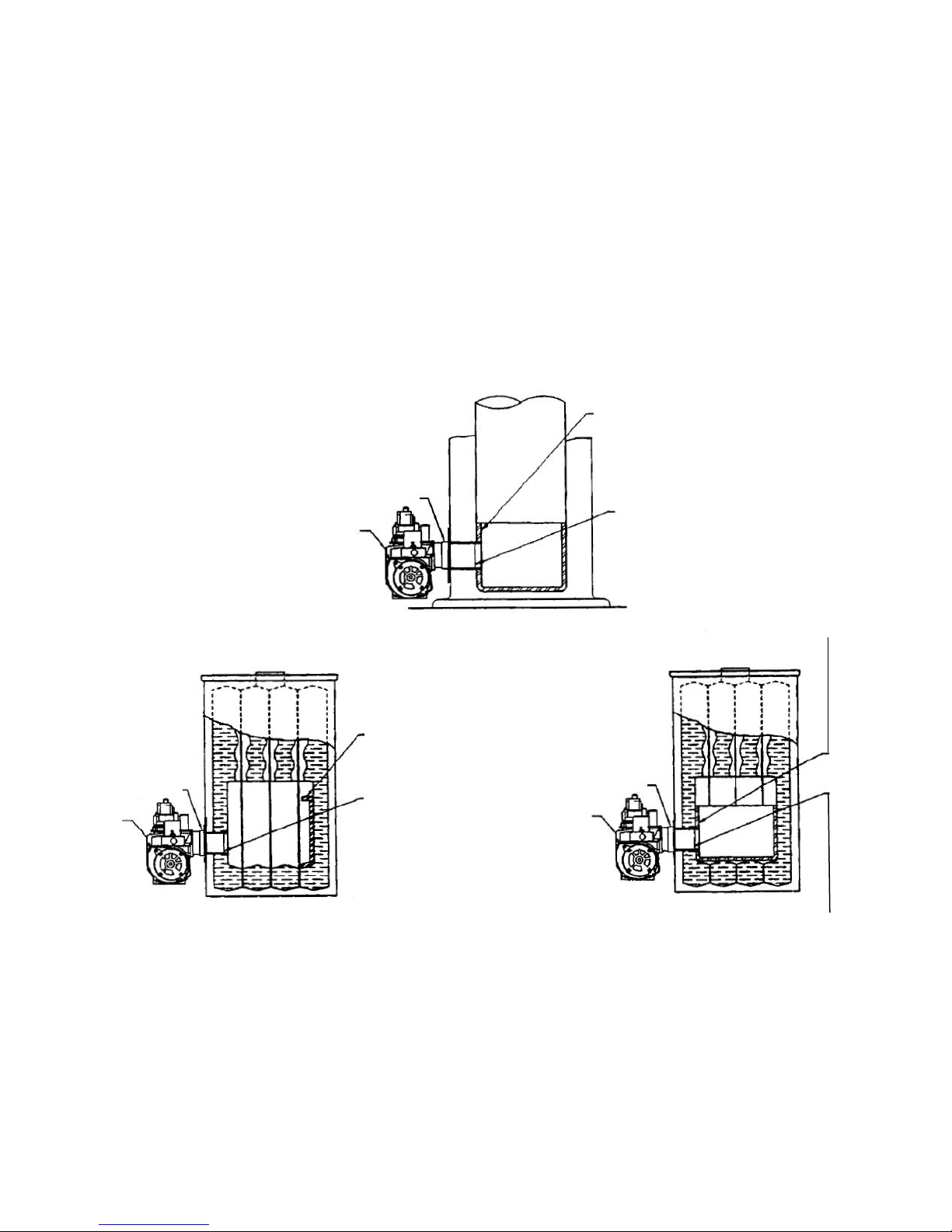
Primary Air Location
Off Cycle Damper Location
INITIAL BURNER START UP PROCEDURE
READ THE APPLICATICABLE SEQUENCE OF BURNER/PRIMARY GAS
CONTROL OPERATION IN SECTION V SERVICE AND TROUBLESHOOTING BEFORE
PROCEEDING.
1. Depress the combination gas valve manual control knob and turn to “OFF” position. (For location of
the manual control knob, refer to Figure 17). Remove the 1/8” NPT pressure tap plug from the gas
valve and install a hose barb fitting. Connect a manometer to the hose barb fitting.
2. Adjust the primary air and off-cycle damper to the start-up settings shown in Figure18.
Figure 18: Air Settings for Initial Start Up
Figure 19: Primary Air and Off Cycle Damper Locations
23
Page 24

3. Turn on the main electrical power and set the thermostat or operation control to call for heat. Allow the
burner to run a MINIMUM of 5 minutes to purge combustion chamber and appliance heat exchanger.
4. Set the thermostat or operating control below room temperature, shutting the burner “OFF” for 1
minute. This is will reset the primary control.
5. Depress the combination gas valve manual control now and turn to “ON” position.
6. Set the thermostat or operating control to call for heat. The burner will start and go through the
applicable sequence of burner/primary gas control operation.
7. On new gas line installations, air may be trapped in the line, the burner may experience several
lockouts until all the air is purged from the lines. If the burner goes into lockout, it may be reset by
adjusting the thermostat or operating control below room temperature for a few seconds, then
readjusting to call for heat.
8. Once burner is running set the manifold pressure by adjusting the gas valve’s pressure regulator while
measuring the gas pressure using a manometer. The correct operating manifold orifice pressure range
for both natural and LP gas is 2.0” w.c. (498 Pa) minimum to 4.0” w.c. (996 Pa) maximum. By
adjusting the pressure regulator between 2.0” w.c. (498 Pa) minimum to 4.0” w.c. (996 Pa) on either
natural or LP gas, a wide input range can be achieved with a single orifice size. If the desired input
rating cannot be obtained within the above manifold orifice pressure adjustment range, the next size
larger or smaller orifice should be used (Refer to orifice chart Figure 11).
9. A more accurate Btu/hr (kW) input can be determined by using the natural gas service meter with only
the burner on (all other gas appliances should be off). The hand on the gas meter dial with the lowest
cubic feet valve (fastest revolving dial), should be clocked for one complete revolution and use the
formula listed below where one complete revolution on the gas meter is equal to one cubic foot of gas.
3600 x ft3 per rev. x Btu value/ft3 = Btu/hr (kW)
3600 x 1 x 1000 = 300,000 Btu/hr (87.9 kW)
Seconds per revolution
EXAMPLE:
12
COMBUSTION ADJUSTMENT OF BURNER
All adjustments below must be made with the following equipment:
1. Draft Gauge 3. CO Tester
2. O2 or CO2 Analyzer 4. Water Column Gauge
ALWAYS USE RELIABLE COMBUSTION TEST INSTRUMENTS.
BEING PROFICIENT IN THE USE OF THESE INSTRUMENTS AND INTERPRETING THEIR DATA
IS NECESSARY FOR SAFE, RELIABLE, AND EFFICIENT BURNER OPERATION.
1. After the burner has been in operation for at least 10 minutes and the off cycle damper and primary air
shutter were set per Figure 18, assuring combustion chamber and heat exchanger are fully warmed,
take combustion analysis flue gas samples just ahead of the draft control in the flue pipe. See step 2
for recommended values.
2. For natural gas applications, best performance will be achieved with a CO2 setting of 8% to 10%
(3% to 6.5% O2) and
CO should be minimized with a goal of 100 ppm or less. In no case should CO be above 400 ppm
Air Free.
For LP gas applications, best performance will be achieved with a CO2 setting of 9.5% to 11.8% (3%
to 6.5% O2) and CO should be minimized with a goal of 100 ppm or less. In no case should CO be
above 400 ppm Air Free.
24
Page 25

20.9
(20.9 – %O2)
11.7
% CO2
13.8
% CO2
IF THE BURNER Btu/hr (kW) INPUT IS CHANGED REPEAT COMBUSTION
ADJUSTMENT OF BURNER.
If an O2 analyzer is used:
CO
AIRFREE
= x CO
PPM
If a CO2 analyzer is used:
For Natural Gas: CO
AIRFREE
= x CO
PPM
For LP Gas: CO
AIRFREE
= x CO
PPM
Stack temperatures for furnaces and boilers are recommended to be between 350 and 400 degrees
Fahrenheit.
NOTE: Check overfire draft and adjust to NEGATIVE -0.01 (2.491 Pa) to -0.02 (4.982 Pa) inches w.c.
during burner operation.
If these values are not achieved with the initial settings listed in Figure 18, adjust the primary air
shutter to achieve these values. For the HSG400, if these values are not able to be achieved and the
burner is set to the low end of the firing range, adjust the off cycle damper to a lower setting to adjust
burner. For the HSG200, if these values are not able to be achieved, the off cycle damper setting may
need to be increased to adjust the burner.
3. After the air is adjusted, combustion meets the recommendations in step 2 and the burner is running
properly, be sure to record all set up information and leave it with the burner. With the burner shut off
and the manual control knob in the “OFF” position, remove the hose barb and replace the 1/8” NPT
pressure tap plug. Apply a small amount of thread sealant to the plug before replacing.
The HSG200 and HSG400 can operate on either natural gas or LP gas. To convert an HSG burner from
one gas to another requires changing the orifice, setting of the manifold pressure, and adjusting the air
shutter(s). The HSG200 and HSG400 conversion burners are shipped from the factory with a natural gas
orifice installed and a label on the burner which indicates the burner has a natural gas orifice installed. In
order to convert the burner to fire LP gas, refer to the chart in Figure 11 for selection of the proper orifice
for the desired firing rate. An orifice kit is provided with each burner. The kit also includes a gas
identification label that is designed to be placed over the gas identification label located on the burner.
Place the label for the new gas, natural or LP over the existing label when converting from one gas to
another. Follow the procedure outlined in CHANGING THE ORIFICE and SECTION II: INITIAL START
UP for making the necessary adjustments to the manifold pressure. Follow the procedure in
COMBUSTION ADJUSTMENT OF BURNER for any initial installation, after a change in rate, or a
conversion from one gas to another.
SECTION III: GAS CONVERSION
25
Page 26

PROFESSIONAL SERVICE REQUIRED
Gas burners require the services of an experienced technician
for proper setting and adjustment. If the burner does not appear
to be operating properly, DO NOT ATTEMPT TO ADJUST THE
BURNER YOURSELF, but call in a competent serviceman.
Orifice kits for the HSG200 and HSG400 burners are available from Wayne Combustion Systems.
Some HSG burner models are sold to Original Equipment Manufacturers
and are pre-set with the proper orifice for the firing rate and gas utilization for the specific
equipment. Before attempting to convert this equipment from one gas to another, consult the
equipment manual or contact the equipment manufacturer for the procedure on gas conversion.
SECTION IV: CONSUMER INSTRUCTIONS
GENERAL INSTRUCTIONS FOR SERVICING BURNER
A homeowner should be able to check several possible causes of shutdown before calling in a
serviceman. The following check list may eliminate the need for a service call or at least provide
information for the serviceman.
1. Check thermostat. Make sure that it is set at the desired room temperature. If the thermostat is
damaged or loose on the wall, have it replaced or repaired.
2. Check fuses in service box for the burner circuit. Replaceable type fuses should not be loose in
the socket. If a fuse is blown out or if in doubt, replace with the same size and type. If circuit
breaker is in the service box, check position of indicator. If tripped, reset.
3. Check on-off switch for the burner circuit, it may have been accidentally turned off.
It is advisable, periodically, to visually inspect the burner. Check air inlet blower to make sure it
is not clogged or blocked. Check air shutter to make sure that it has not been tampered with,
make sure that it is in the same position as when final adjustments were made. Check blower
wheel to see if it is dirty or full of lint. The areas around the conversion burner should be kept clear
and free of combustible materials, gasoline and other flammable vapors and liquids. The flow of
combustion and ventilating air to the burner must not be blocked or obstructed in any manner.
CLEANING OF BURNERS (BY SERVICEMAN ONLY): Remove the burner from the appliance and
visually inspect the blast tube for any deterioration. Check burner head, electrodes, etc. with
illustrations in the owner’s manual for proper locations.
26
Page 27

NUMBER OF FLASHES
ERROR
GREEN
NORMAL OPERATION
1
NO FLAME DURING TRIAL
3
GAS VALVE RELAY FAIL
4
LINE VOLTAGE ERROR
5
INTERNAL CONTROL ERROR
SECTION V: SERVICE AND TROUBLESHOOTING
HSG SERIES BURNER UTILIZING WAYNE 64420 SERIES IGNITION CONTROLS
HSG burners with a spec number that contains a “D,” for example, 62377D, use Wayne ignition controls.
Older burners that have a spec number containing a “C” use a Honeywell control. See next sections for
information on these controls. Spec numbers can be found on HSG burners on a small label located below
the T-shaped label on the back of the burner.
WIRING BURNERS USING WAYNE IGNITION CONTROLS
These burners ship with black, white, and green wires exiting the junction box via its conduit connection
point. The black and white wires are used for testing at the factory and should be removed and discarded.
After that, connect incoming L1 to the connector where the black wire was and L2 where the white wire
was. Use a wire nut to connect earth ground to the green wire. Failure to connect earth ground to the
green ground wire will cause the ignition control to lock out with a “LINE Voltage Error” fault.
WAYNE IGNITION CONTROL ERROR CODES
Table 4: Error Codes for Wayne Control
SEQUENCE OF OPERATION – HSG SERIES POWER GAS CONVERSION BURNER
UTILIZING WAYNE 64420-001 IGNITION CONTROL WITH EXTERNAL
30 SECOND PRE-PURGE TIMER P/N 62388-001 AND RESISTOR P/N 62530-001
On a call for heat,120 Vac goes to the motor, and 24Vac goes to the air switch. Once the motor reaches
operating rpm, combustion air pressure closes the air proving switch, energizing the external 30 second
pre-purge timer. After the 30 second pre-purge timing, the ignition control is energized.
After the initial 30 second pre-purge provided by the external timer, the Wayne control is energized, and it
will activate the gas valve allowing gas to flow to the burner head. Simultaneously, the ignition control
energizes the ignition transformer, producing a spark at the electrode, establishing main burner flame.
This trial for ignition period lasts four (4) seconds and occurs at the beginning of every heat cycle.
Normally, burner flame will be established before the end of this period. Once the flame is established and
the trial for ignition ends, sparking will cease and the flame rod will provide flame monitoring to the ignition
control for the remainder of the heat cycle.
When utilizing the Wayne 64420-001 control with the eternal 30 second pre-purge timer, a 10K ohm
resistor is wired in parallel between the output terminals of the 30 second pre-purge timer and the input
terminal to the ignition control. The function of this resistor is to keep a load on the output terminal of the
external 30 second pre-purge timer, after the initial call for heat and 30 second start pre-purge.
This promotes immediate re-ignition of the main burner flame after initial 30 second pre-purge provided by
the external timer, overriding the need for a separate pre-purge for each heat cycle. This control scheme is
used in oven or similar applications where process temperatures must remain constant.
If the flame is extinguished during the heat cycle, the ignition control will attempt to re-establish the main
burner flame. If this does not occur within the trial for ignition period, the ignition control will go into lockout,
de-energizing the gas valve and ignition transformer. Then, the LED on the ignition control will flash an
error code. These error codes are listed on the ignition control’s label near the LED and in Table 4 above.
To restart the system, the main power or thermostat must be de-energized momentarily, then reenergized. If at any time during the heat cycle, there is an insufficient supply of combustion air to the
burner, the air switch will open, putting the system into lockout and closing the gas valve.
See Figure 25 for the wiring diagram for burners with the Wayne 64420-001 control.
27
Page 28

SEQUENCE OF OPERATION – HSG SERIES POWER GAS CONVERSION BURNER
UTILIZING WAYNE P/N 64420-002 IGNITION CONTROL W/BUILT IN 30 SECOND PRE-PURGE
On a call for heat, 24V goes to the motor start relay and air switch. Once the motor reaches operating rpm,
combustion air pressure closes the air proving switch, energizing the ignition control.
This Wayne ignition control has an internal 30 second pre-purge timer. After the initial 30 second prepurge, the control simultaneously energizes the gas valve and ignition transformer. Gas flows to the burner
head and the transformer produces a spark at the electrode establishing main burner flame.
At the start of each heat cycle, there is a trial for ignition period of four (4) seconds duration. Normally,
burner flame will be established before the end of this period. Once the flame is established and the trial
for ignition ends, sparking will cease and the flame rod will provide flame monitoring to the ignition control
for the remainder of the heat cycle. If the flame should be extinguished during the heat cycle, the ignition
control will attempt to establish the main burner flame. If this does not occur within the trial for ignition
period, the ignition control will go into lockout de-energizing the gas valve and ignition transformer. The
LED on the ignition control will flash an error code in this case. These error codes are listed on the ignition
control’s label near the LED and in Table 4 above.
To restart the system, the main power or thermostat must be de-energized momentarily, then reenergized. If at any time during the heat cycle, there is an insufficient supply of combustion air to the
burner, the air switch will open, putting the system into lockout closing the gas valve.
See Figure 26 for the wiring diagram for burners with the Wayne 64420-002 control.
HSG SERIES BURNER UTILIZING HONEYWELL IGNITION CONTROLS
SEQUENCE OF OPERATION – HSG SERIES POWER GAS CONVERSION BURNER
UTILIZING HONEYWELL S89E GAS PRIMARY P/N 62758-002 WITH EXTERNAL
30 SECOND PRE-PURGE TIMER P/N 62388-001 AND RESISTOR P/N 62530-001
On a call for heat, voltage (24V) is applied to the motor start relay and air switch. Once the blower motor
reaches operating rpm, combustion air pressure causes the air proving switch to close, the contacts
energize the external 30 second pre-purge timer. After the 30 second pre-purge timing, the S89E is
energized.
The S89E gas primary control has an internal 8 second safe start check. After the initial 30 second prepurge provided by the external timer, the S89E gas primary control is energized, the 8 second safe start
check will commence. Once this is accomplished, the S89E activates the gas valve allowing gas to flow to
the burner head. Simultaneously, the S89E control energizes the ignition transformer, producing a spark at
the electrode, establishing main burner flame.
At the start of each heat cycle, there is a trial for ignition period of four (4) seconds duration. Normally,
burner flame will be established before the end of this period. Once the flame is established, sparking will
cease and flame sensor will provide flame monitoring to the S89E gas primary control for the remainder of
the heat cycle.
When utilizing the S89E gas primary control with the eternal 30 second pre-purge timer, a 10K ohm
resistor is wired in parallel between the output terminals of the 30 second pre-purge timer and the input
terminal to the S89E gas primary control. The function of this resistor is to keep a load on the output
terminal of the external 30 second pre-purge timer, after the initial call for heat and 30 second start prepurge and 8 second safe start check.
This promotes simultaneous re-ignition of the main burner flame after the S89E’s 8 second safe start
check, overriding the 30 second pre-purge. This control scheme is used in oven or similar applications
where process temperatures must remain constant.
Should the flame be extinguished during the heat cycle, the S89E primary ignition control will go into the 8
second safe start check after which time it will re-energize the gas valve and ignition transformer in an
attempt to re-establish the main burner. If this does not occur within the 4 second trial for ignition period,
S89E gas primary control will go into lockout de-energizing the gas valve and ignition transformer. To
28
Page 29

restart the system, the main power or thermostat must be de-energized momentarily, then re-energized. If
at any time during the heat cycle, there is insufficient supply of combustion air to the burner, the air switch
contacts will open, putting the system into lockout closing gas valve.
See Figure 27 for wiring diagram of HSG Series Burner utilizing the Honeywell S89E control.
SEQUENCE OF OPERATION – HSG SERIES POWER GAS CONVERSION BURNER
UTILIZING HONEYWELL S89F P/N 62759-002 IGNITION CONTROL W/BUILT IN 30 SECOND PRE-
PURGE
On a call for heat, voltage (24V) is applied to the motor start relay and air switch. Once the fan motor
reaches operating rpm, combustion air pressure causes the air proving switch to close, and the contacts
energize the ignition control.
The ignition control has an internal 30 second pre-purge timer. After the initial 30 second pre-purge, the
ignition control simultaneously energizes the gas valve and ignition transformer. Gas flows to the burner
head and the transformer produces a spark at the electrode establishing main burner flame.
At the start of each heat cycle, there is a trial for ignition period of four (4) seconds duration. Normally,
burner flame will be established before the end of this period. Once the flame is established and sparking
ceases, the flame sensor will provide flame monitoring to the ignition control for the remainder of the heat
cycle. If the flame should be extinguished during the heat cycle, the S89F ignition control will go into the 30
second pre-purge and 8 second safe start check, then re-energize the gas valve and ignition transformer in
an attempt to establish the main burner flame. If reignition does not occur within the trial for ignition period,
the ignition control will go into lockout de-energizing the gas valve and ignition transformer.
To restart the system, the main power or thermostat must be de-energized momentarily, then reenergized. If at any time during the heat cycle, there is an insufficient supply of combustion air to the
burner, the air switch will open, putting the system into lockout closing the gas valve.
See Figure 28 for the wiring diagram for HSG Series burners using the Honeywell S89F control
FLAME SENSING ON HSG SERIES BURNERS
The ignition control utilizes the flame current rectification principal for main burner flame sensing.
The flame rectification phenomenon occurs as follows: The ignited gas flame causes the immediate
atmosphere around the flame to become ionized (gas atoms become electrically charged). The ionization
causes the atmosphere around the flame to become electrically conductive. An ac voltage output from the
ignition control sensing circuit is routed through the flame sensor probe. When the flame sensor probe and
burner head are both in contact with a properly adjusted flame, the burner head with its larger surface
attracts more free electrons, thus becoming negatively charged. The flame sensor probe with its small
surface area gives up free electrons, thus becoming positively charged. The free electrons from the ac
voltage in the flame sensor probe flow through the ionized gas flame to the grounded burner head. As the
ac current passes through the gas flame, it is rectified into a dc current flowing back to the grounded side
of the sensing circuit. The flame in actuality is a switch. When the flame is present the switch is closed
allowing current to flow through the sensing circuit of the control. When no flame is present, the switch is
open with no current flowing through the sensing circuit of the control.
The dc current flow is measured in units called dc microamperes. This current can be measured by
disconnecting the wire from the Sense terminal and connecting the probes of a meter that can measure
microamps between that wire and the sense terminal. A steady dc microampere current of 0.2 minimum (.8
microamps for Honeywell controls) or higher through the sensing circuit of the primary ignition control is
sufficient to keep the burner running without a safety lockout. See Figure 20 for flame current
measurement.
29
Page 30

Figure 20: Flame Current Measurement, Top: Wayne control; Bottom: Honeywell control
30
Page 31

PROBE
DIM “A” REF
IGNITER
1 5/8 in (41.3mm)
FLAME SENSOR
1 1/4 in (31.8mm)
Figure 21: Igniter and Flame Sensor Probe Settings
Figure 22: Burner Face and Flame Sensor Probe Location
31
Page 32

Check voltage input to burner, 120 VAC.
Check low voltage transformer for 24 volt
output. 24 VAC should be present across
terminals 1 and 3 of the motor start relay.
OK
OK
Check for 120 volts AC between terminal
2 and ground and terminal 4 and ground
on motor start relay.
OK
Check electrical wiring and connections.
Does motor shaft turn freely?
OK
OK
Replace motor.
Diagnose reason for
absence of voltage.
NO
NO
OK
Replace 24VAC
Transformer
Check electrical wiring
and connections.
NO
OK
Replace motor
start relay.
1. Check for blower clearance.
2. Lubricate motor bearings if
applicable.
NO
OK
Check continuity though 24 volt T-STAT if
used, or if burner is cycled on-off through
120V circuit, T-T terminals must have
jumper wire.
NO
Check electrical wiring
and connections.
Repair T-STAT or add
jumper as necessary.
OK
TROUBLESHOOTING GUIDE PRIMARY IGNITION CONTROLS
MOTOR DOES NOT START
32
Page 33

Reset Control – Motor starts – Completes 30 second pre-purge cycle and 4 second trial for
ignition. NOTE: the burner motor will continue to operate during the lockout mode when the
thermostat circuit is called for burner operation.
OK
OK
Check for correct orifice/air setting relationship (Figures 11, 18, 19).
In order for the following functional test to be made, the
control must be reset and the tests monitored during the
4 second trial for ignition period that occurs at the END
of the 30 second pre-purge.
Check for 24 volts AC at gas valve terminals.
OK
Make sure leads are on the correct gas valve
terminals.
OK
Check for correct manifold regulated pressure (see
Figure 11 for pressure, Figure 17 for location of
pressure port on valve.)
Replace gas valve.
OK
NO
Check electrical wiring and
connections. Be sure leads are
on correct gas valve terminals.
Replace primary ignition control.
OK
OK
IGNITION ARC ESTABLISHED – NO FLAME
33
Page 34

1. Reset Control
Motor starts – Completes 30 second pre-purge cycle.
Gas valve opens, regulating adequate gas pressure.
No flame established – Primary control locks out after 4 second trial for ignition period.
In order for the functional test described in Step 2 to be
made, the control must reset and the voltage measured
during the 4 second trial for ignition period that occurs at
the end of the 30 second prepurge.
2. Check for 120 volts AC between the neutral line and
the junction of the blue primary control lead and black
ignition transformer lead.
3. Check electrical wiring and connections at ignition
transformer.
4. Check high voltage lead and connection to igniter
electrode.
5. Inspect igniter electrode for cracked ceramic insulator
and correct spark gap (Figure 21).
6. Replace ignition transformer.
Check electrical wiring and
connections.
Check for 120 volts AC between the
neutral line and the other blue wire of
the primary control. Check for 120
volts AC between the neutral line and
the black wire of the primary control.
NOTE: 120 volts AC at these 2 points
should be present when the motor is
turning.
Replace primary ignition
control.
OK
OK
OK
OK
OK
OK
NO
NO IGNITION ARC ESTABLISHED
34
Page 35

NUMBER OF FLASHES
ERROR
GREEN
NORMAL OPERATION
1
NO FLAME DURING TRIAL
3
GAS VALVE RELAY FAIL
4
LINE VOLTAGE ERROR
5
INTERNAL CONTROL ERROR
OK
OK
OK
OK
3. Check for 24VAC across the
primary control terminals labeled
“VALVE” and “GND (VALVE)”.
Note: Voltage must be checked during
the 4 second trial for ignition.
NO
Replace ignition control
Check for 24 volts AC at the 24 volt primary control input
terminals labeled “24V” and “GND (24V)”.
OK
Check air proving switch for:
a. Any impairment that would keep it from closing
or opening.
b. Electrical continuity; switch is normally open.
c. Replace switch as necessary.
Check (when applicable) external 30
second pre-purge timer (jumper
around timer from air switch). Should
primary ignition control become
energized, replace timer.
NO
Check the 24VAC transformer
for 24 volt output. If no voltage,
replace transformer. Check
connections between
transformer and ignition control.
Reset Control – Motor starts- After 30 second pre-purge cycle, motor continues to run but
flame is not established.
In order for the following functional test to be made, the control must reset and the tests
monitored during the 4 second trial for ignition that occurs at the end of the 30 second
prepurge cycle.
If using a Wayne control, check the diagnostic LED for an error code. If a “LINE VOLTAGE
ERROR,” is indicated check the connection between earth ground and the burner chassis.
NO IGNITION – NO GAS FLOW
Wayne Control Error Codes
35
Page 36

NUMBER OF FLASHES
ERROR
GREEN
NORMAL OPERATION
1
NO FLAME DURING TRIAL
3
GAS VALVE RELAY FAIL
4
LINE VOLTAGE ERROR
5
INTERNAL CONTROL ERROR
If using a Wayne control, check the diagnostic LED for an error code. Consult the table below to
troubleshoot the issue.
Disconnect flame sensor lead from primary control.
Connect (+) positive lead (dc) microampere meter to
the primary control terminal. Connect the (-) negative
microampere meter lead to the flame sensor lead
terminal. Check polarity of L1 and L2. L1 to ground,
120 volts. L2 to ground 0 volts. See Figure 20: Flame
current measurement.
Reset control, after pre-purge cycle, flame is
established. A stable microampere current of .
0.2 (0.8 for Honeywell controls) or more is
required for dependable operation.
Flame sensor microampere reading is too weak
or unstable.
Probable causes of erratic lockout
1. Flame proving circuit grounded by
moisture.
2. Damaged insulation on flame sensor
lead.
3. Flame sensor improperly positioned
in flame (see Figure 21).
4. Poor ground path to primary control.
5. Defective primary control.
6. Read manual section “Flame
Sensing”.
7. Deposits on flame sensor. Refer to
Troubleshooting Guide Section.
8. Insure ground rod at end of air tube
is in place.
9. Applicable only to Honeywell S89
series primary ignition controls:
Connect L1 to the black lead and L2
to the white lead exiting the S89
otherwise the S89 will not detect the
flame and will lock out.
Probable causes:
1. Extremely poor combustion level.
2. Flame sensor improperly positioned
in flame.
3. Defective primary control.
Reset Control
Completes 30 second pre-purge cycle.
Flame is established.
Sometimes the control locks out before thermostat or controlling circuit is satisfied
LOSES FLAME DURING CYCLE – CONTROL LOCKS OUT ON SAFETY
36
Page 37

Check for proper thermostat installation and location.
If thermostat is used, remove wires at T-T terminals
and replace with jumper wire. If burner runs properly,
check thermostat for proper operation.
Check thermostat heat anticipator for correct setting.
Check low voltage circuit for bad wiring, electrical
connections and/or switches.
Check line voltage circuit for bad wiring, electrical
connections and/or switches.
OK
OK
OK
Set the anticipator to the correct value
if adjustable type. If proper setting
cannot be made, replace with
compatible thermostat.
OK
BURNER CYCLES ERRATICALLY
NOTE: When the thermostat wires terminate on the HSG primary control box “T” terminals, the heat
anticipator setting value for the HSG burner is determined by adding the primary control current to the gas
valve current. The result is the anticipator setting. (Example: 0.2 + 0.6 = 0.8 amps).
If the thermostat wires ARE NOT terminated on the burner control box “T” terminals and these terminals
are JUMPERED, you must then determine what the correct anticipator setting is by inspecting the
controlling device at the point where thermostat wires terminate. Typically, this information can be found on
the body or cover of the controlling device.
When determining the current draw of the dual head gas valve, be sure to consider the separate ampere
values for each valve. These usually are stenciled on the valve body, and must be added together to
obtain the correct sum. (Example: 0.4 + 0.2 = 0.6 amps). When the current draw cannot be determined
accurately by the above method, measure the current with an ampere meter using 1 AMP scale. Connect
the meter leads in series with one of the thermostat leads for the accurate reading.
37
Page 38

BURN HAZARD, HOT SURFACE
Burner flange and air tube are hot when burner is in operation. Do not
service this area during or immediately after operation. Allow area to
cool.
ELECTRICAL SHOCK HAZARD
Make sure the main manual gas valve, manual control knob on the
combination valve and electrical supply are turned off before opening
burner or removing any parts for service.
SERVICING HSG SERIES BURNER
(SERVICE TECHNICIAN ONLY)
A. BURNER HEAD AND ELECTRODE/SENSOR ASSEMBLY
The burner head, electrode, sensor probe, combination valve, orifice housing and housing cover are
part of the gas train assembly which can be removed as one unit (see Figure 23).
1. Disconnect the gas supply line from the combustion gas valve inlet; disconnect flame sensor lead wire
from gas primary, gas valve lead wires from gas valve operator and (orange) ignition lead wire from
ignition transformer ignition lead wire.
2. Remove the two 1/4” hex slotted screws on the top front of the housing cover and the two 5/16” hex
slotted screws on the left and right side back of the housing cover.
3. To remove gas train assembly, gently lift up rear of housing cover pulling rearward slightly on the
drawer assembly gradually positioning the rear of the drawer assembly upward 90 degrees. Gently extract
burner head and electrode/sensor assembly out of opening in housing taking extreme care to not dislocate
or damage igniter electrode or flame sensor.
4. When servicing, clean burner head ports, igniter electrode and flame sensor. Inspect the flame sensor
and electrode wires and porcelain insulators carefully for hairline cracks which will degrade performance.
Replace as necessary.
5. Examine the igniter electrode and flame sensor for any serious corrosion or deterioration of metal at
the tips. Check for proper dimensional settings of the flame sensor and electrode (See Figure 21). Adjust
and/or replace these assemblies as necessary. Make sure that the ignition and sensor probe wires go to
the correct electrodes and the ignition wire boot is in place over the electrode porcelain.
6. Make sure that the burner tube end is properly positioned in the combustion chamber entry. It must be
set 1/8” (3.2 mm) short of the inside face of the combustion chamber as shown in Figures 6, 7, 8.
B. AIR PROVING SWITCH
The air proving switch is mounted to the housing cover with (2) #6 self-tapping screws under the gas valve.
A clear plastic tube, protected by a spring cover, is connected to the barbed fitting on the pressure switch
while the other end is connected to a brass barbed fitting. The plastic tube allows pressurized air from the
blower housing to travel to the pressure switch causing diaphragm contacts to close thus completing the
circuit.
The function of the air proving switch is to ensure combustion air is being developed by the blower motor
and blower wheel. Should the blower motor fail or the blower wheel malfunction, the burner gas valve will
shut off.
1. The air proving switch should never require maintenance. However, should nuisance lockouts occur,
the pressure switch can be checked. This is done by disconnecting the yellow and white leads from the Air
Proving switch and jumpering the leads together. If the burner functions correctly, the switch needs to be
replaced.
38
Page 39

Electrical Hazard
If a jumper is used to check the pressure switch it must be removed
or an unsafe operating condition can occur resulting in personal
injury or death.
2. As mentioned above, the switch should never require maintenance. However a pinched tube will shut
off the flow of pressurized air to the diaphragm creating a failure made similar to bad air proving switch.
Always check to ensure that the clear tubing is not pinched. Make sure the spring cover is reinstalled over
the tube.
3. Switch is mounted in the horizontal position with terminals up from factory. Final burner mounting
should maintain horizontal switch position.
Damage to internal components of burner may result, if air proving switch
is mounted in another position other than horizontal.
C. COMBUSTION AIR BLOWER AND MOTOR
1. Cleaning of the combustion air blower is indicated if the blades show an accumulation of dust and lint,
or if the character of the flame indicates a deficiency of combustion air.
2. The side plate, motor and blower wheel are removed as one assembly. Disconnect the motor wire
inside the junction box beneath the ignition transformers. Remove the four 5/16” hex slotted screws
securing side plate to fan housing.
Do not remove blower wheel from motor shaft during periodic cleaning.
3. Should removal of the blower wheel be necessary for cleaning or replacement of it or the motor, the
blower wheel must be positioned correctly on the motor shaft (Figure 24).
HSG200 blower wheel part number 21664 is positioned 2 1/16” (52.4mm) measured from the
blower wheel inlet ring face to the side plate face.
HSG400 blower wheel part number 21642 is positioned 2 3/16” (55.6 mm) measured from the
blower wheel inlet ring face to the side plate face.
39
Page 40

Figure 23: HSG Gas Train Assembly (INDIVIDUAL PARTS ONLY SOLD SEPARATELY.
REFERENCE SECTION VI FOR PART NUMBERS)
Figure 24: MOTOR/BLOWER ASSEMBLY
Nuisance Lockouts/Flame Sensing Problems –HSG200 & HSG400 Gas Burners
Wayne’s HSG series direct spark ignition (DSI) gas burners prove flame through the process of flame
rectification. Flame rectification is achieved by the ignition control as it places a small voltage on the flame
sensor. When the flame sensor is surrounded by flame, the voltage on the flame sensor “leaks” to ground
through the flame, resulting in an electrical current. This current is interpreted by the ignition control as the
presence of flame.
One of the most common problems with gas appliances utilizing this type of electronic flame sensing
system is the “nuisance lockout”. Lockouts are not generally due to the burner failing to ignite, but rather
TROUBLESHOOTING GUIDE
40
Page 41

simply the failure of the system to sense the establishment of the flame. Should this situation exist for a
period of time longer than the ignition control’s stated lockout timing, the control will shut down or go into
permanent lockout. The only way to get the burner to recycle is to break, and then reinstate power to the
burner.
The following situations can lead to flame sensing problems and can be checked without
disassembling the burner:
The burner is not properly grounded to “earth ground” of the supply voltage.
The ignition control is not properly grounded to the burner itself. Using an ohm meter, check the wire
attached to both parts for good contact and continuity.
The burner ignition control is polarity sensitive. The polarity of the incoming line voltage may be
reversed. Verify that black and white wires are hot and neutral respectively, and that they are
connected to the corresponding black and white wires on the burner.
The remaining checks and/or adjustments require removal of the gas train:
The connections from the “SENSE” terminal of the ignition control to the end of the flame sensor may
be broken at some point. Check all quick connect terminations and connections. Check the continuity
with an ohmmeter while flexing wires to assure no hidden conductor breakage exists. If replaced,
wiring must be of equal or heavier gauge and equal or better temperature rating.
The flame sensor probe may be grounded out. Assure that the flame sensor probe is not touching the
burner head. The flame sensor should be positioned in the center of the clearance groove on the outer
edge of the burner head with approximately 1/16” (1.5875mm) clearance from the head. The flame
sensor must not be positioned too far away from the head as this may result in grounding out of the
flame sensor against the inside surface of the air tube.
The flame sensor probe should be free of soot and creosote. Deposits may insulate the probe, leading
it not to pass the electrical charge to the flame. The probe can be cleaned with steel wool, emery
paper or extra fine sandpaper.
Deposits on the flame sensor probe are the leading cause of nuisance
lockouts in dual-fuel wood/gas fired appliances.
The flame sensor probe may be burned away. Check it against dimensions on the IGNITER AND
FLAME SENSOR PROBE SETTINGS drawing (Figure 21).
The dimensional location of the flame sensor probe may be incorrect, or the probe may be bent out of
shape. Check it against dimensions on the IGNITER AND FLAME SENSOR PROBE SETTINGS
drawing and adjust if necessary.
The spark electrode gap may be incorrect, resulting in no spark or an inadequate spark that will not
ignite the gas properly. Check the electrode gap against the IGNITER AND FLAME SENSOR PROBE
SETTINGS drawing and adjust if necessary.
The high tension lead conductor from the ignition transformer to the tip of the spark electrode may be
broken, preventing the high voltage current from getting to the electrode tip. Check all connections
thoroughly and/or check to continuity of the lead wire assembly with an ohmmeter.
Once all of the items listed previously have been carefully checked and corrected as necessary, re-insert
the gas train assembly into the burner. NOTE: be careful not to bend the air proving switch sail arm (if so
equipped) or accidentally reposition with the flame sensor probe or igniter electrode during reinstallation of
the gas train assembly.
If, after all of the above listed items have been carefully checked, the burner still fails to work, it is due one
of or more of the following problems:
1. Unit sparks and fires but will not stay lit. Ignition control module is malfunctioning and must be
replaced.
2. Unit does not spark. Ignition transformer is bad and must be replaced.
41
Page 42

HSG WIRING DIAGRAMS
HSG SERIES BURNER WITH WAYNE 64420-001 IGNITION CONTROL
Figure 25: Wiring Diagram for Burners with Wayne 64420-001 Control
42
Page 43

HSG SERIES BURNER WITH WAYNE 64420-002 IGNITION CONTROL
Figure 26: Wiring Diagram for Burners with Wayne 64420-002 Control
43
Page 44

HSG SERIES BURNER WITH HONEYWELL S89E GAS PRIMARY CONTROL
Figure 27: Wiring Diagram for Burners with Honeywell S89E Control
44
Page 45

HSG SERIES BURNER WITH HONEYWELL S89F GAS PRIMARY CONTROL
Figure 28: Wiring Diagram for Burners with Honeywell S89F Control
45
Page 46

HSG200/400 PARTS LIST
Item
Part No.
Description
1
100934-001
Burner Housing
2
62576-SER6
Air Tube - HSG200 6" (152.4mm)
63270-004
Air Tube - HSG400 6 1/4" (158.75mm)
62576-SER9
Air Tube - HSG200 9" (228.6mm)
63270-015
Air Tube - HSG400 9" (228.6mm)
62576-SER12
Air Tube - HSG200 12" (304.8mm)
63270-027
Air Tube - HSG400 12" (304.8mm)
63270-028
Air Tube - HSG400 15" (381mm)
3
62393-SER
Air Cone - (HSG200 only) (not shown)
4
21724-011
Adjustable Flange Assembly (includes gasket, not shown)
5
100428-002
Flange Gasket (not shown)
6
21664
Blower Wheel 5 1/4" OD (133.35mm) (HSG200)
21642
Blower Wheel 5 1/2" OD (139.7mm) (HSG400)
7
21658
Side Plate
8
20627
Motor, split phase 1/7 HP (0.107 kW) 3450 RPM 120V/60
24001-001
Motor, 1/7 HP (0.107 kW) 2850 RPM 230V 50/60 Hz
9
100373-002
Combustion Air Inlet damper
10
62408-001
Control Box (S89E & S89F)
11
62388-001
30 second Pre-purge Timer (Used with P/N 62758-002) (Special Limit Applications Only)
62530-001
Resistor Wire Assembly
12
60186-004
24 Volt Transformer 120V
64404-001
24 Volt Transformer 230V 50/60 Hz
100450-001
Bushing
13
62406-002
Motor Relay
14
62759-002
Ignition Control Honeywell S89F with 30 sec. Pre-purge
62758-002
Ignition Control Honeywell S89E with 0 sec. Pre-purge (Special Limit Applications Only)
64420-002
Ignition Control, Wayne with 30 sec. Pre-purge
15
100377-002
Damper Indicator Pointer
16
100429
Damper Decal
15-16
100373-KIT
Includes 100373-002, 100429, 100377-002 and 100410
17
63263-005
Pressure Switch
63272-005
Pressure Switch Conversion Kit
63935-001
Pressure Switch (230V/50Hz)
18
60178-002
Thermostat Terminal Strip
19
100372
Adjustment Arm Off-Cycle Damper
20-21
100371-KIT
Off-cycle Damper Kit (not shown)
22
21319
Junction Box (under Ignition Transformer)
23
61843
Lighting Plate
24
62407-001
Ignition Transformer 120V/60 Hz
24
64051-001
Ignition Transformer 230V 50/60 Hz
25
62391-002
Electrode Assembly
26
62390-002
Sensor Probe (flame sensor) Assembly
27
62387-001
Insulator Bushing (QTY 2 REQUIRED ON HSG BURNER)
28
62575-002
Chamber/Manifold - HSG200 6" (152.4mm)
62575-001
Chamber/Manifold - HSG400 6 1/4" (158.75mm)
62575-014
Chamber/Manifold - HSG200 9" (228.6mm)
62575-012
Chamber/Manifold - HSG400 9" (228.6mm)
62575-026
Chamber/Manifold - HSG200 12" (304.8mm)
62575-024
Chamber/Manifold - HSG400 12" (304.8mm)
62575-031
Chamber/Manifold - HSG400 15" (381mm)
29
62419-001
Clip, Electrode Bracket
30
61951-001
Igniter Support Parts Kit (INCLUDES 62419-001 and 62387-001) (not shown)
31
62411-028
11" (279.4mm) Sensor Wire - 6" (152.4mm), 6 1/4" (158.75mm) Burner
62411-030
14" (355.6mm) Sensor Wire - 9" (228.6mm), 12" (304.8mm) Burner
62411-068
17" (431.8mm) Sensor Wire - 15" (381mm) Burner
64096-001
Sense Wire - 330mm Cable (230V 50/60 Hz)
PARTS LIST CONTINUED ON NEXT PAGE.
SECTION VI: PARTS LIST AND EXPLODED VIEWS
46
Page 47

HSG200/400 PARTS LIST CONT.
Item
Part No.
Description
32
62909-001
8" (203.2mm) Ignition Wire - S89E & S89F controls only; 6", 6 1/4" Burner
62909-003
14" (355.6mm) Ignition Wire- S89E & S89F controls only; 9”, 12", 15" Burner
64095-001
Ignition Wire - 500mm Cable (230V 50/60Hz) Use with 64051-001 Ignition Transformer
64460-001
8” Noise Suppression Ignition Wire, Use with Wayne controls; 6", 6 1/4" Burner
64460-002
14” Noise Suppression Ignition Wire, Use with Wayne control; 9", 12", 15" Burner
33
62404-002
Top Plate/Housing Cover
34
62304
Strain Relief Bushing/Ignition Wire
62402-KIT
Includes items 35 - 38
35
62402-001
Orifice Housing
36
62410-001
Orifice Spring
37
62401-001
Orifice Gasket
38
62385-001
Orifice Cap
39
----------------
Orifice (Location Reference Only) See Item 41
40
62374-004
Gas Valve Honeywell VR8305M 4801
41
62459-001
Orifice Package -HSG200 (not shown)
62459-002
Orifice Package -HSG400 (not shown)
42
21760-011
Option Pedestal Mounting (not shown)
43
64635-001
Mounting Plate, Wayne Control
HSG EXPLODED VIEWS
Figure 29: Junction Box Assemblies Exploded
47
Page 48

Figure 29 continued: Junction Box Assemblies Exploded
Figure 30: Motor Assembly Exploded
48
Page 49

Figure 31: Gun Assembly Exploded
Figure 32: HSG Series Burner Exploded
49
Page 50

13.2 (335 mm) REF.
7.7 in (195mm)
7 in (178 mm)
15.25 in
(377 mm)
Figure 33: Outer Dimensions of HSG Series Burner
50
Page 51

4. A burner so repaired will then carry the LIMITED
WARRANTY equal to the unexpired portion of the
original burner LIMITED WARRANTY.
5. If inspection by WAYNE does NOT disclose any
defect covered by this LIMITED WARRANTY, the
burner or burner component(s) will be either
repaired or replaced at the expense of the
customer and WAYNE’S regular charges will apply.
6. If the original manufacturer of a burner component
offers a warranty greater than either of our
LIMITED WARRANTIES described above, then
this portion will be added to our LIMITED
WARRANTY.
This LIMITED WARRANTY does NOT cover products
which have been damaged as the result of accident,
abuse, misuse, neglect, improper installations,
improper maintenance or failure to operate in
accordance with WAYNE’s written instructions.
These LIMITED WARRANTIES do not extend to
anyone except the first purchaser at retail and only
when the burner is in the original installation site.
IMPLIED WARRANTIES OF MERCHANTABILITY
AND FITNESS FOR A PARTICULAR PURPOSE
SHALL BE LIMITED TO THE DURATION OF THE
LIMITED EXPRESS WARRANTIES CONTAINED
HEREIN. WAYNE EXPRESSLY DISCLAIMS AND
EXCLUDES ANY LIABILITY FOR CONSEQUENTIAL
OR INCIDENTAL DAMAGES OF ANY NATURE FOR
BREACH OF ANY EXPRESS OR IMPLIED
WARRANTY.
Some states do not allow limitation on how long an
implied warranty lasts, so the above limitation may not
apply to you. Also, some states do not allow the
exclusion or limitation of incidental or consequential
damages, so the above limitation or exclusion may not
apply to you. WAYNE neither assumes or authorizes
any person to assume for WAYNE any other liability or
obligation in connection with the sale of these products.
This warranty gives you specific legal rights, and you
may also have other rights which vary from state to
state.
LIMITED WARRANTIES FOR OIL AND
GAS BURNERS, MADE BY WAYNE AND
USED IN RESIDENTIAL INSTALLATIONS
WAYNE COMBUSTION SYSTEMS (“WAYNE”)
warrants to those who purchase its Oil Burner Models
for resale or for incorporation into a product of resale,
that its burner is free from defects in material and
workmanship under normal use and service for thirty-six
(36) months from the date of manufacture. ALL GAS
BURNERS manufactured by “WAYNE” will be similarly
warranted for eighteen (18) months from date of
manufacture except where original manufacture offers a
greater warranty. (Reference #6 below) THESE LIMITED
WARRANTIES DO NOT APPLY UNLESS THE BURNER
COVERED BY IT IS PROPERLY INSTALLED BY A
QUALIFIED, COMPETENT TECHNICIAN, WHO IS
LICENSED WHERE STATE AND/OR LOCAL CODES
PREVAIL, AND WHO IS EXPERIENCED IN MAKING
SUCH INSTALLATIONS, IN ACCORDANCE WITH
NFPA #31 OF THE NATIONAL FIRE PROTECTION
ASSOCIATION AND IN ACCORDANCE WITH ALL
LOCAL, STATE AND NATIONAL CODES.
Any IN-WARRANTY burner component which is
defective in material or workmanship will be either
repaired or replaced as follows:
1. Fuel pumps, motors, transformers, gas valves, and
controls should be returned to an authorized service
station or distributor of WAYNE for determination of
applicability of this LIMITED WARRANTY as to
either repair or replacement, where said service
station or distributor is reasonably available in the
customer’s locality. The manufacturers of burner
components regularly publish and distribute listings
showing the locations of their network of service
stations. Where such local service is NOT available
for the burner components described above or other
burner parts are involved, these items should be
returned, freight prepaid, to WAYNE Service
Department, 801 Glasgow Ave, Fort Wayne,
Indiana 46803.
2. Burners and/or component(s) determined to be
covered under this LIMITED WARRANTY by
WAYNE shall be repaired or replaced at W AYNE’s
sole option.
3. WAYNE is not responsible for any labor cost for the
removal and replacement of said burner or burner
components and equipment associated therewith.
SECTION VII: WARRANTY
51
Page 52

NOTES
52
 Loading...