

Page 1
See Warranty on page 8 for important information about commercial use of this product.
Operating Instructions and Replacement Parts List
Please read and save these instructions. Read carefully before attempting to assemble, install, operate or maintain the product described. Protect
yourself and others by observing all safety information. Failure to comply with instructions could result in personal injury and/or property damage!
Retain instructions for future reference.
Engine Driven
GPS400
A
N
R
C
U
E
S
S
P
A
R
Need
O
G
R
A
Y
T
I
L
A
U
Assistance?
Q
Call Us First!
1-800-237-0987
M
Centrifugal Pump
Description
The Wayne pumps are general use
centrifugal water pumps. The pump is
equipped with a Viton® seal assembly
that is also compatible with many
agricultural chemicals.
Safety Guidelines
This manual contains information that is
very important to know and understand.
This information is provided for SAFETY
and to PREVENT EQUIPMENT PROBLEMS.
To help recognize this information,
observe the following symbols.
Danger indicates an
imminently hazardous
situation which, if not avoided, WILL
result in death or serious injury.
Warning indicates a
potentially hazardous
situation which, if not avoided, COULD
result in death or serious injury.
Caution indicates a
potentially minor or
moderate injury.
Notice indicates
important
information, that if not followed, may
cause damage to equipment.
General Safety
Information
CALIFORNIA PROPOSITION 65
This product or its
power cord may
contain chemicals known to the State
of California to cause cancer and birth
defects or other reproductive harm. Wash
hands after handling.
Never run
an enclosed area. Exhaust
gases contain deadly
poisonous carbon monoxide,
which has no odor or taste.
Do not use
to pump
flammable or explosive fluids
such as gasoline, fuel oil,
kerosene, etc. Do not use in
flammable and/or explosive atmospheres.
Pump should only be used with liquids
compatible with pump component materials.
Failure to follow this warning can result in
personal injury and/or property damage.
2. Observe all safety precautions for the
handling of the fuel.
Do not
hot engine. Fuel spilled on a
hot engine could result in a
fire or explosion. Do not
refuel a running engine.
3. Pump should be located and should
rest on a level solid foundation. Do
not suspend pump by means of the
discharge pipe.
Be sure pump is on
doesn’t fall over.
4. Do not use torches or apply excessive
heat, fire or flames to this pump as an
explosion may result.
5. Before working on the unit, insulate
the wire from the spark plug, by
disconnecting the spark plug wire from
the spark plug.
Complete pump and
1. Know the pump application,
limitations, and potential hazards.
Read these rules and the instructions
carefully. Failure to follow them could
cause serious bodily injury and/or
property damage.
MUST be protected against below freezing
temperature. Failure to do so could cause
serious damage and voids the warranty.
6. Do not run pump dry. Water is
required to lubricate the shaft seal.
REMINDER: Keep your dated proof of purchase for warranty purposes!
Attach it to this manual or fi le it for safekeeping.
engine in
refuel a
secure footing so it
piping system
7. Pumping chemicals or corrosive liquids
with this pump may shorten the life of
the pump and may be hazardous to the
operator.
8. Personal Safety:
a. Wear safety glasses at all times when
working with pumps.
b. Keep work area clean, uncluttered
and properly lighted; replace all
unused tools and equipment.
c. Keep visitors at a safe distance from
the work area.
d. Make workshop child-proof with
padlocks, master switches, and by
removing starter keys.
9. This pump is designed for non-abrasive
fluid transfer; do not use as a trash
pump. Always use a suction strainer with
this pump to filter abrasive material.
Abrasive materials such as sand and
gravel will shorten the life of the pump.
Installation
This pump is designed to be self-priming
when installed and operated as specified
below.
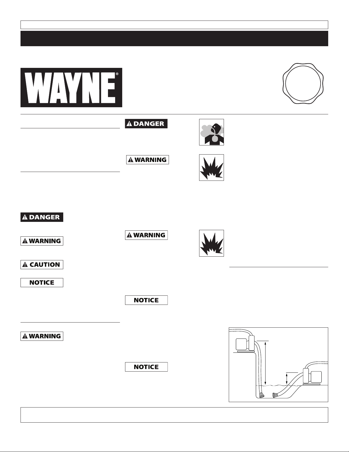
1. The pump should be placed as close as
possible to the water being pumped.
A pump with 20 foot suction lift will
not remove water as quickly as a pump
with 5 foot suction lift (Figure 1).
20 Ft. Suction Lift
5 Ft.
Suction
Lift
Figure 1
© 2010 WAYNE Pumps
For parts, product & service information
visit www.waynepumps.com
320604-001 8/10
Page 2
Operating Instructions and Replacement Parts List
Installation (continued)
2. Suction hose and fitting must be
airtight.
An air leak in the
prevent priming of the pump. Use of
thread sealant is recommended.
suction line may
Suction lines must be reinforced hose
or rigid pipe. Non-reinforced hose will
collapse due to the suction created
by the pump and prevent pump from
operating.
3. A check valve must be used in the
suction line to maintain the selfpriming capability. If no check valve is
used the pump will need to be primed
at the start of each operation. For best
operation, the check valve should be
installed at the intake of the suction
line.(Figure 2).
Check valve
Figure 2
4. A suction strainer is required to filter
abrasive material. Abrasive material,
such as gravel, will destroy the pump
and void the warranty. This pump
is not designed to handle abrasive
materials.
5. The discharge hose and fitting should
be leak-tight. A leak in the discharge
hose will allow water to spray
around the work site, making the site
hazardous.
6. Keep all pipes and hose lines as short
and straight as possible. Long lengths
and curves in the pipes and hose lines
will reduce the pressure the pump
develops.
7. Fill the engine crankcase with oil.
Refer to the engine operating manual
for the specific grade of oil and
amount required.
8. Fill the engine fuel tank with
gasoline. Refer to the engine
operating manual for specific gasoline
type that is most efficient for this
engine.
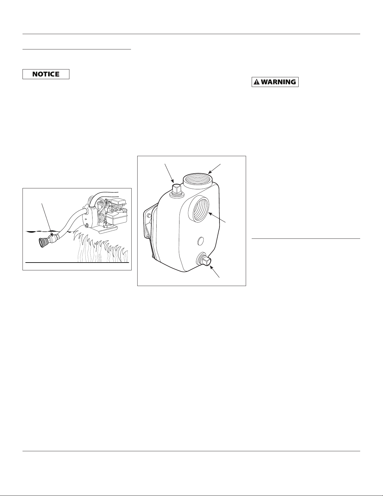
9. Add water to the priming port on
the pump (See Figure 3). Continue
adding water until the water level is
approximately 3 inches from the top.
Install the priming plug. The water in
the pump will create the suction that
primes the pump.
Priming port
Figure 3
Discharge
Suction
Drain port
10. Turn fuel valve to ‘ON’ position
11. Move choke level to ‘CHOKE’ position.
12. Move the engine switch to ‘ON’
position.
13. Pull engine crank until engine starts.
Once engine starts, move choke lever
to ‘RUN’ position.
14. The pump will take several minutes to
prime.
PIPING
Always place the pump as close as possible
to the water being pumped. Keep all pipe
and hose lines as short and straight as
possible.
Support pump and
piping when
assembling and after installation. Failure
to do so may cause piping to break, pump
to fail, etc; all of which can result in
property damage and/or personal injury.
All suction connections must be airtight.
If the pump won’t prime, check for leaks
in the suction piping or fittings. If flexible
suction hose is used instead of pipe, use
reinforced hose with a two inch inner
diameter. Non-reinforced flexible hose may
collapse from the vacuum created as the
pump primes.
Always use a strainer at the end of the
suction pipe or hose. Position strainer so
it doesn’t become clogged with stones
or debris. A suction line check valve is
recommended.
Do not use this pump for suction lifts over
twenty-five feet.
Maintenance
Always shut off the engine, allow the
engine to cool, and remove the spark plug
before performing any maintenance.
During freezing weather, open the drain
port and allow all the water in the pump
to drain. This will prevent damage to the
pump when the water freezes. If the pump
will be stored for a month or more, drain
the water from the pump and follow the
engine manufacturer’s recommendations
for long-term storage.
www.waynepumps.com
2
Page 3
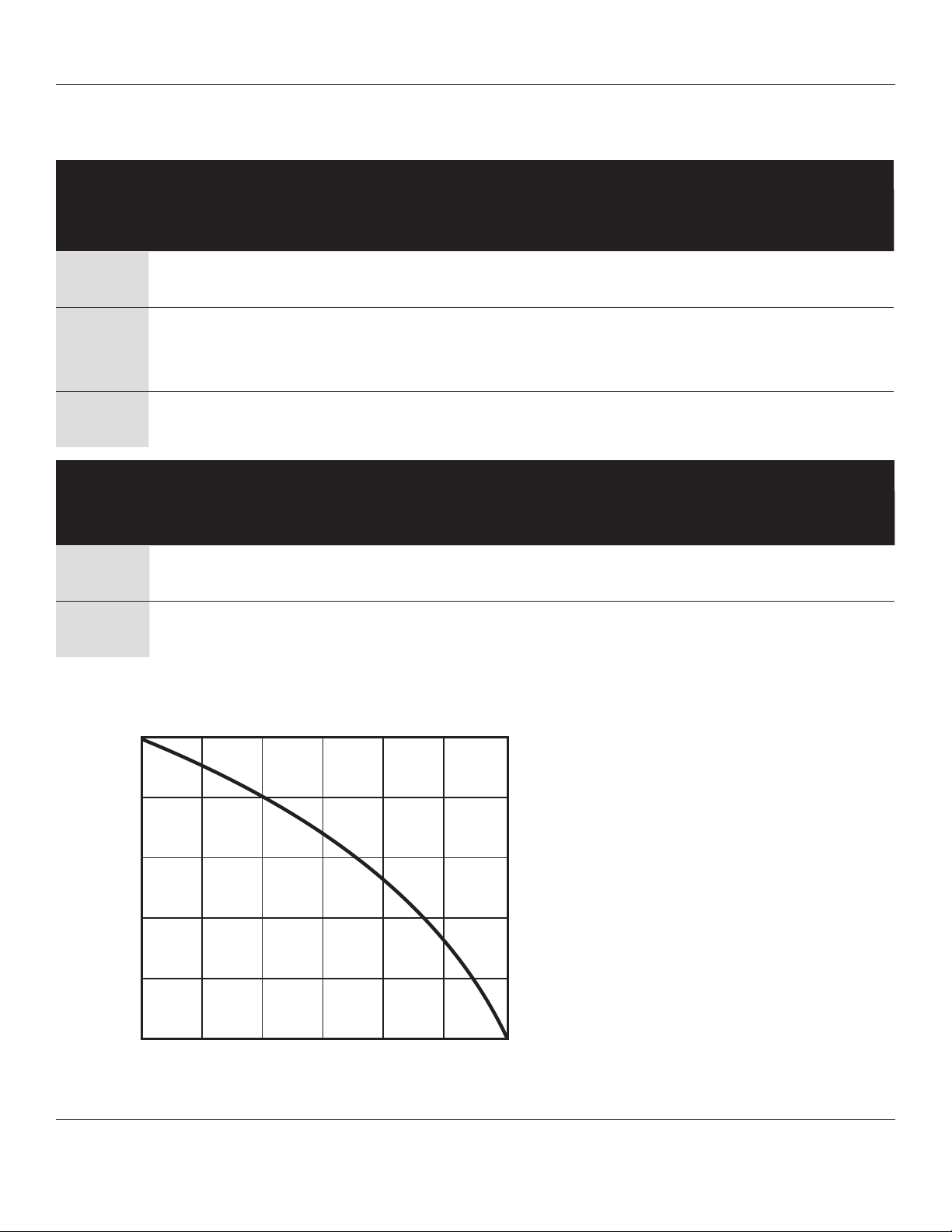
Performance Information
y
2” Cast Iron Pump Performance
CAPACITIES IN GALLONS PER HOUR
Discharge
Head Feet
20 6600 6420 6180 6000 5640 5220
30 6180 6000 5640 5220 4800 4380
40 5640 5220 4800 4380 4080 3660
50 4800 4380 4080 3660 3300 2820
60 4080 3660 3300 2820 2400 1800
70 3300 2820 2400 1800 1260 720
80 2400 1800 1260 720 0 0
0 5 10 15 20 25
FEET FRICTION LOSS IN 100 FEET OF PLASTIC PIPE
Dynamic Suction Lift - Feet
GPS400
Pipe
Size
1 1/
4
1 1/
2
2 1.2 1.6 2.8 4.2 5.8 9.9 15.0 21.2
2 1/
2
20 25 30 40 50 60 80 100 120
5.6 8.5 11.9 20.2 30.5
2.6 4.0 5.5 9.4 14.3 19.9 34.2
Gallons Per Minute
1.2 1.8 2.5 4.2 6.3 8.8
PERFORMANCE CURVE
100
80
60
40
20
Total Dynamic Head - FEET
0
1200 2400 3600 4800 6000 7200
Capacit
- GPH
www.waynepumps.com
3
Page 4

Operating Instructions and Replacement Parts List
For Pump Accessories, call 1-800-237-0987
Please provide following information:
- Model number
- Serial number (if any)
- Part description and number as shown
SUCTION HOSE
PART #16510-002
• Reinforced to prevent collapse under
suction
Hose coupled both ends with 2” hose
thread. One 20 ft. hose per carton
LAY FLAT DISCHARGE HOSE
PART #16511
• Economical
• Lightweight
• Resistant to oils, light chemicals,
abrasion and sunlight
• Will not rot, mildew or absorb water
Hose couples one end with 2” hose
thread. One 25 ft. hose per carton
Address parts correspondence to:
WAYNE Pumps
101 Production Drive
Harrison, OH 45030
2” SUCTION STRAINER
PART #66036
• Prevents stones, leaves and other
debris from clogging pump
www.waynepumps.com
4
Page 5

For Replacement Parts or Technical Assistance,
call 1-800-237-0987
GPS400
Please provide following information:
- Model number
- Serial number (if any)
- Part description and number as shown
8
13
4
Address parts correspondence to:
WAYNE Pumps
101 Production Drive
Harrison, OH 45030
1
10
2
5
3
3a
6
9
11
7
Item No. Description Part Number Qty
1 Engine 57800-001 1
2 Volute Bracket 56724-001 1
3 & 3a Impeller kit with shims 66057-WYN1 1
4 Screw 17046-001 1
5 Key 16997-001 1
®
6 Shaft seal kit (VITON
7 Volute 56723-001 1
8 Pipe plug, 3/4 NPT 15921 2
9 Volute gasket 15556-002 1
10 Cap screw, 5/16 - 18 x 1 12701 5
11 Cap screw, 5/16 - 24 x 7/8 16209 4
12 Lock washer, split 5/16 (not shown) 15916 4
13 Handle 56722-001 1
14 Base 11007-001 1
) 56712 1
14
www.waynepumps.com
5
Page 6

Operating Instructions and Replacement Parts List
Notes
www.waynepumps.com
6
Page 7

Maintenance / Service Record
Date Maintenance Performed Replacement Components Required
GPS400
www.waynepumps.com
7
Page 8

Operating Instructions and Replacement Parts List
GPS400
Limited Warranty
For one year from date of purchase, WAYNE Water Systems (”WAYNE Pumps“) will repair or replace, at its option, for the
original purchaser any part or parts of its Sump Pumps or Water Pumps (”Product“) found upon examination by WAYNE
Pumps to be defective in materials or workmanship. Please call WAYNE Pumps (800-237-0987) for instructions or see your
dealer. Be prepared to provide the model number when exercising this warranty. All transportation charges on Products or
parts submitted for repair or replacement must be paid by purchaser.
This Limited Warranty does not cover Products which have been damaged as a result of accident, abuse, misuse, neglect,
improper installation, improper maintenance, or failure to operate in accordance with WAYNE Pumps' written instructions.
THERE IS NO OTHER EXPRESS WARRANTY. IMPLIED WARRANTIES, INCLUDING THOSE OF MERCHANTABILITY AND
FITNESS FOR A PARTICULAR PURPOSE, ARE LIMITED TO ONE YEAR FROM THE DATE OF PURCHASE. THIS IS THE
EXCLUSIVE REMEDY AND ANY LIABILITY FOR ANY AND ALL INDIRECT OR CONSEQUENTIAL DAMAGES OR EXPENSES
WHATSOEVER IS EXCLUDED.
Some states do not allow limitations on how long an implied warranty lasts, or do not allow the exclusions or limitations of
incidental or consequential damages, so the above limitations might not apply to you. This limited warranty gives you specific
legal rights, and you may also have other legal rights which vary from state to state.
In no event, whether as a result of breach of contract warranty, tort (including negligence) or otherwise, shall WAYNE Pumps
or its suppliers be liable for any special, consequential, incidental or penal damages including, but not limited to loss of profit
or revenues, loss of use of the products or any associated equipment, damage to associated equipment, cost of capital, cost of
substitute products, facilities, services or replacement power, downtime costs, or claims of buyer’s customers for such damages.
You MUST retain your purchase receipt along with this form. In the event you need to exercise a warranty claim, you MUST
send a COPY of the purchase receipt along with the material or correspondence. Please call WAYNE Pumps (800-237-0987) for
return authorization and instructions.
DO NOT MAIL THIS FORM TO WAYNE PUMPS. Use this form only to maintain your records.
MODEL NO._____________________ SERIAL NO.___________________________ INSTALLATION DATE ______________________
ATTACH YOUR RECEIPT HERE
www.waynepumps.com
8
 Loading...