

Page 1
EN
WT004139
2008-03-20 V0 Rev.01.0
Global Vista CNG
Instruction Manual
Page 2
© Copyright
2008-03-20 V0 Rev.01.0
- 2 - WT004139
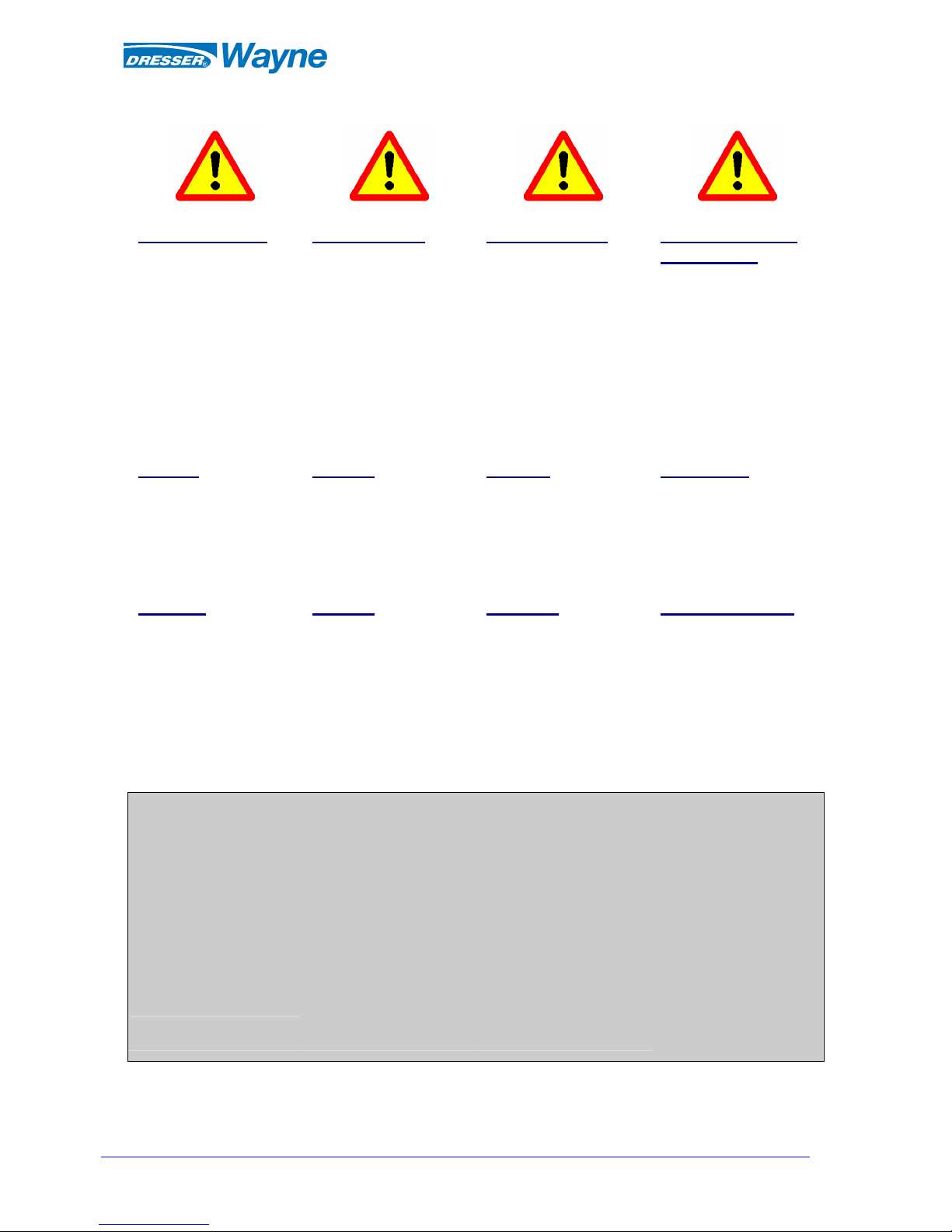
Product Liability
The supplier’s product
liability is only valid if no
alterations, additions etc.
have been made to the
equipment without the supplier’s express permission.
Use only genuine parts.
Produktansvar
För att en leverantörs
produktansvar skall gälla får
ändringar, kompletteringar
och liknande ej göras i utrustningen utan leverantörens godkännande.
Originalreservdelar skall
alltid användas
.
Produkthaftung
Damit die Produkthaftung
des Lieferanten ihre
Gültigkeit behält, dürfen
ohne ausdrückliche
Genehmigung des
Lieferanten keine
Änderungen, Ergänzungen
o. Ä. an der Ausrüstung
vorgenommen werden.
Verwenden Sie nur
Originalteile.
Oтветственнoсть
пoставщика
Для сохранения
ответственности нельзя
вводить в оборудование
изменения, дополнения и
т.п. без разрешения
поставщика. Пользуйтесь
только оригинальными
запасными частями,
выпущенным
изготовителем
бензоколонки.
Caution
To prevent damage that
might result in electric shock
or fire, disconnect the main
power prior to any work.
Varning
Gör pumpen/enheten strömlös innan Du gör ingrepp i
den. I annat fall föreligger
risk för skada.
Vorsicht
Um Beschädigungen zu
vermeiden, die zu einem
elektrischen Schlag oder
Feuer führen können,
unterbrechen Sie vor jeder
Arbeit die Stromzufuhr.
Осторожно
Во избежание поражения
электрическим током или
пожара отключайте напряжение питания перед
началом любых работ.
Warning
Never run a leaking pump!
Be careful with the environment and mind the skidding
risk; take care of leaking fuel
immediately.
Varning
Använd aldrig en läckande
pump.
Tänk på miljön och halkrisken, sanera utläckt drivmedel snarast.
Warnung
Lassen Sie nie eine undichte
Zapfsäule laufen! Seien Sie
umweltbewusst und denken
Sie an die Rutschgefahr;
beseitigen Sie austretenden
Kraftstoff umgehend.
Предупреждение
Не пользуйтесь колонкой
при наличии утечки
топлива! Охраняйте
окружающую среду,
помните об опасности
скольжения: в случае
утечки топлива на
дорожное покрытие возле
колонки, примите меры
немедленно.
The contents of this
publication may not be
copied either wholly or
in part without the
consent of Dresser
Wayne AB.
Dresser Wayne AB
reserves the right to
change specifications
contained in the text and
illustrations without
notice.
Innehållet i denna publikation får ej helt eller
delvis kopieras utan
medgivande från
Dresser Wayne AB.
Dresser Wayne AB förbehåller sig rätten att
utan särskilt meddelande
ändra specifikationer
givna i text och bild.
Der Inhalt dieses
Handbuches darf ohne
die Erlaubnis von
Dresser Wayne weder
ganz noch teilweise
kopiert werden.
Dresser Wayne behält
sich das Recht vor,
textliche oder bildliche
Inhalte ohne besondere
Mitteilung zu ändern.
Не разрешается
копировать полностью
или частично содержание
настоящей публикации
без разрешения фирмы
Dresser Wayne АВ.
Dresser Wayne АВ
оставляет за собой право
вносить изменения в
спецификации,
содержащиеся в тексте и
иллюстрациях, без
предварительного
уведомления.
Page 3

© Copyright
2008-03-20 V0 Rev.01.0
- 3 - WT004139
Index
General Warnings............................................................................................4
Warnings for fuel station operators...............................................................4
Consulting the manual....................................................................................................................................5
Warnings and safety.......................................................................................................................................5
Protection from pressure-related risks............................................................................................................ 5
Preventing CNG leaks....................................................................................................................................5
Breakaway devices.........................................................................................................................................5
Electrical installation / Preventing electrical shocks ......................................................................................6
Dispenser Identification .................................................................................................................................6
Main technical characteristics ........................................................................................................................ 6
Main technical characteristics ........................................................................................................................ 7
Operating principles....................................................................................................................................... 7
Electrical system ............................................................................................................................................ 7
Typical operating diagram ............................................................................................................................. 8
START-UP........................................................................................................8
Transportation, unpacking and handling internal components.......................................................................8
Installation......................................................................................................................................................9
Initial start-up............................................................................................................................................... 16
Dispensing procedure...................................................................................................................................16
COMPONENTS.............................................................................................17
Hydraulic components.................................................................................................................................. 17
Electrical components..................................................................................................................................17
HYDRAULIC COMPONENTS...................................................................18
Manual ball valve.........................................................................................................................................18
Particulate filter............................................................................................................................................18
Check valve..................................................................................................................................................18
Mass-flow meter...........................................................................................................................................18
Motorized valve ...........................................................................................................................................18
Pressure gauge..............................................................................................................................................18
Delivery hose ...............................................................................................................................................18
Delivery Nozzle ...........................................................................................................................................18
Three-way valve...........................................................................................................................................19
Breakaway Device........................................................................................................................................ 19
ELECTRICAL COMPONENTS.................................................................19
Electronic head.............................................................................................................................................19
Electrical components used in hazardous areas............................................................................................20
MAINTENANCE...........................................................................................20
Relieving pressure from the dispenser..........................................................................................................21
Cleaning.......................................................................................................................................................21
Disassembling / Scrapping the dispenser ..................................................................................................... 21
OPERATIONAL PROCEDURES ON THE ELECTRONIC HEAD......22
Changing prices............................................................................................................................................22
Operational modes of the dispenser .............................................................................................................23
Further information......................................................................................................................................23
ID PLATE.......................................................................................................24
DECLARATION OF CONFORMITY........................................................25
NOTES............................................................................................................26
MARKET & SERVICE ................................................................................27
Page 4
© Copyright
2008-03-20 V0 Rev.01.0
- 4 - WT004139
The descriptions and illustrations in this manual are not binding.
DRESSER reserves the right to make any modifications it considers necessary to make technical improvements
or for any other structural or commercial reason, at any time and without having to update the present
publication. Modifications will not compromise the essential characteristics of the equipment.
General Warnings
• Before using this equipment, read carefully the instructions in this manual in order to effectuate a
correct carry out transportation, start-up and ordinary maintenance.
• Dresser is not responsible for any operations not listed in this manual. In case of breakdown, failure or
malfunction, refer exclusively to the Maintenance Company or Dresser itself.
• Dresser declines responsibility for any damage to things and/or persons due to non-compliance with
safety rules.
• The safety rules in this manual are an integration and not a replacement of the laws in effect in those
countries where this equipment is installed. It is assumed that the station operators have full
knowledge of the safety rules of the country where they operate.
• In case of doubts regarding the proper functioning of the equipment, please refer to the maintenance
company or to Dresser itself to obtain any necessary instructions.
• In case of breakdowns and/or malfunctions of the pump or of its components, refrain from performing
any intervention that may compromise the safety of the equipment. Refer exclusively to the
maintenance company of Dresser itself.
• Periodically check the safety devices in compliance with the instructions of this manual and ensure
they are in perfect condition.
• Dresser will not be held responsible for any tampering performed by the customer, who in this case will
be the only party held liable by the competent authorities.
• For further information on the main components of the equipment (mass flow meter, actuator, board,
etc) and/or original spare parts, see the specific technical documentation given to your technical
assistance/after-sales company.
Warnings for fuel station operators
• The station manager and attendant must carefully read this manual before starting the equipment. We
also recommend keeping this manual throughout the operational life cycle of the equipment, without
adding or modifying anything.
• The customer will be held responsible for any damages due to corrosion, incrustation, pollution,
oxidation, dust, wear-and-tear and gradual deterioration of the product for which conformability limits
have not been set. The customer will also be responsible for any damages related to improper use or
maintenance of the product. Furthermore the customer will also be responsible for any damages
caused by any modifications to the product without prior consent by Dresser, in particular modifications
that are not compliant to what was established in the initial purchase order.
• The use of non-original spare parts by the customer will discharge Dresser from any responsibilities
and from any compensation.
• The GLOBAL VISTA CNG dispenser has the marking guaranteeing that the equipment has been
manufactured in conformity with the applicable EU directives. The dispenser leaves the factory
equipped with the CE declaration of conformity (see the last page of this manual). The CE declaration,
just like this manual, must be kept and shown upon request by the competent authorities, in case of
inspections and/or tests. Any modifications to the product that have not been previously approved by
Dresser will invalidate the declaration of conformity.
Page 5
© Copyright
2008-03-20 V0 Rev.01.0
- 5 - WT004139
Consulting the manual
The GLOBAL VISTA CNG compressed natural gas dispenser is used in areas that are potentially dangerous
and with flammable products.
We recommend scrupulously to follow the precautions and warnings described hereafter. Non-compliance
with the rules listed in this manual could potentially bring serious damages to things or persons.
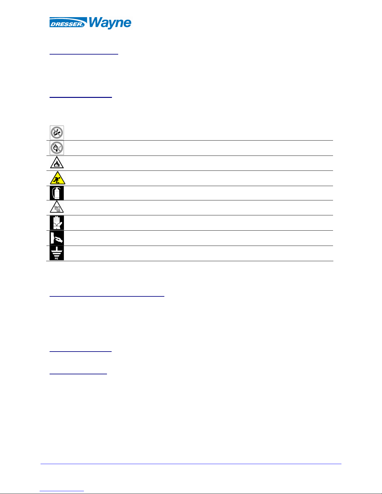
Warnings and safety
Always follow safety precautions in the CNG area of the fuelling station.
Display the following the signs in clearly visible areas:
NO SMOKING
NO OPEN FLAMES
FLAMMABLE PRODUCTS
TRIPPING HAZARD
PERIODICALLY INSPECT THE PROPER FUNCTIONING OF THE EXTINGUISHERS
RISK OF EXPLOSION
ALWAYS USE PROPER PERSONAL PROTECTION
DISCONNECT ALL ELECTRICAL CONNECTIONS BEFORE WORKING ON THE
DISPENSER
VERIFY PROPER FUNCTIONING OF GROUNDING SYSTEM
The positions of these warnings depend on local conditions but they must be visible from the dispenser.
Ensure that all station attendants know how to behave in an emergency situation
Protection from pressure-related risks
The hydraulic circuit of the dispenser works under pressure.
Before performing any maintenance, accurately close the cut-off valve/s located at the base of the dispenser
and release the internal circuit pressure. Pay particular attention in releasing pressure, as, if not performed
properly, some sections of the hydraulic circuit can remain under pressure due to the presence of check
valves and/or motorized valves. To release the dispenser pressure follow the instructions mentioned later on
in the manual.
Preventing CNG leaks
Take all the necessary measures to prevent any gas leaks.
Breakaway devices
In some countries the use of breakaway devices are obligatory by law. We recommend it nonetheless even in
countries where it is not compulsory, in order to guarantee interruption of gas flow in case of an accidental
pull on the hose.
Page 6
© Copyright
2008-03-20 V0 Rev.01.0
- 6 - WT004139
Electrical installation / Preventing electrical shocks
-
Ensure a correct power supply
Never open the CPU when the dispenser is powered.
Never disconnect cables when the dispenser is powered.
Before opening the dispenser for maintenance, always disconnect all power connections.
-
During maintenance, prohibit or restrict access to the switches used to interrupt power supply to
the dispenser.
-
Ensure that the fuelling station has both an electrical line equipped with an automatic breakaway
device as well as a proper grounding system in compliance with all applicable regulations.
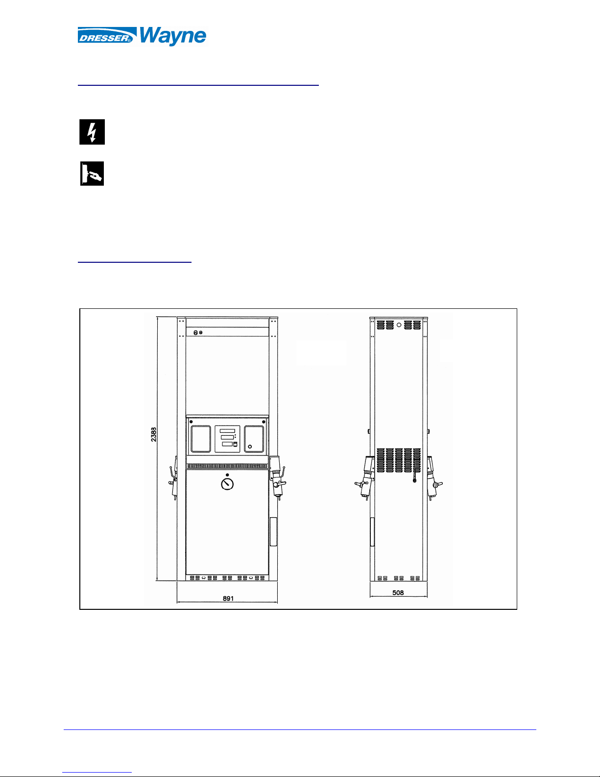
Dispenser Identification
The GLOBAL VISTA CNG dispenser can be manufactured in different versions due mainly to the different
hydraulic configurations.
The following drawing illustrates the general shape and dimensions of the standard model:
B SIDE
A SIDE
Page 7
© Copyright
2008-03-20 V0 Rev.01.0
- 7 - WT004139
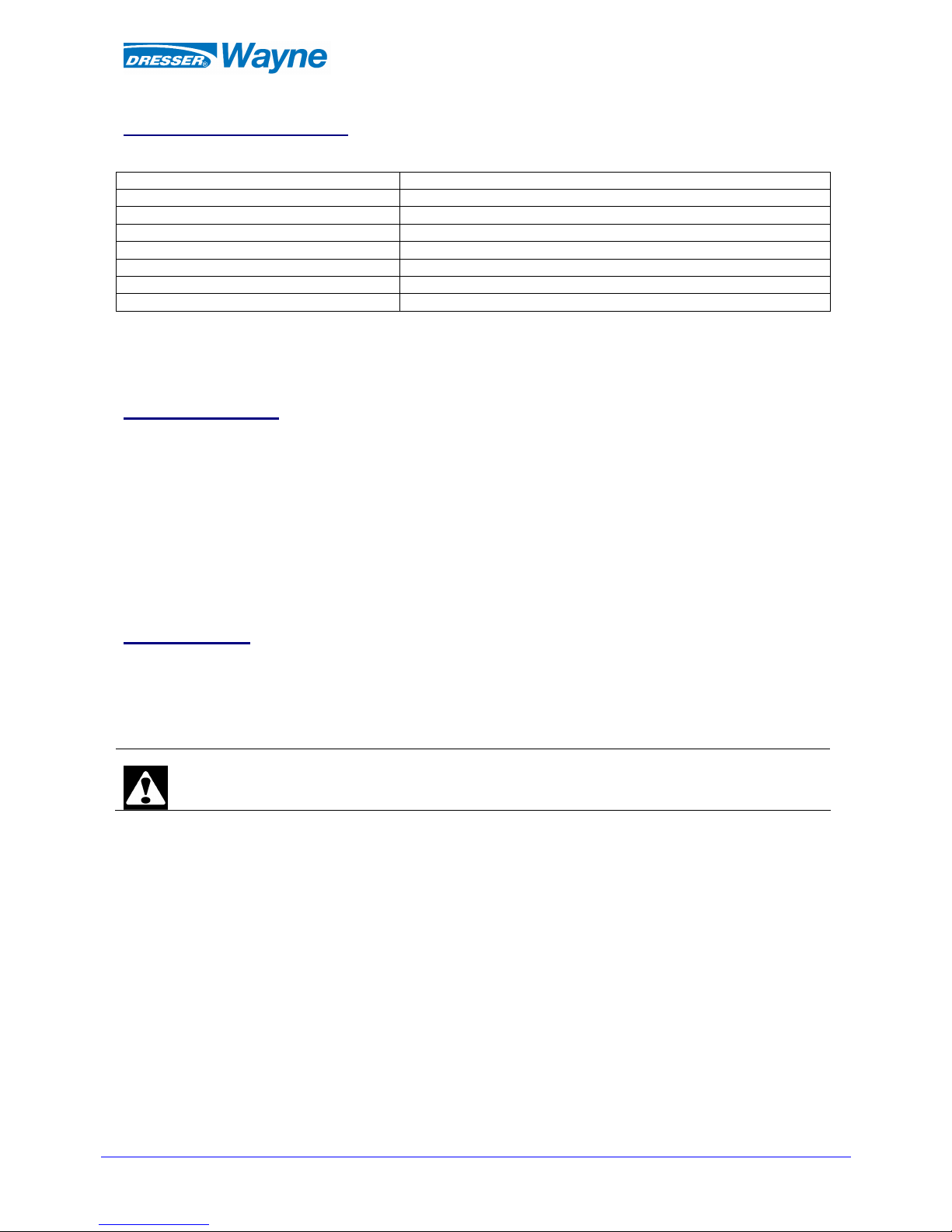
Main technical characteristics
The main technical characteristics of the GLOBAL VISTA CNG dispensers are listed in the following table:
Maximum flow 77 kg/min
Minimum flow 0,06 kg/min
Minimum measurable quantity 5 kg
Measuring accuracy ± 1%
Maximum working pressure 250 bar
Power supply 230 Vac +15 -25% 50-60 Hz
Storage and working temperatures -20°C ÷ +40°C
Approximate weight (with packaging) Min. 200 kg - Max. 300 kg
The function of the CNG dispenser is to fill compressed natural gas into vehicle tanks. Dresser CNG
dispensers can pump both at high flow and standard flow and can therefore fuel all vehicles using CNG, such
as automobiles, vans, buses and trucks.
Operating principles
The compressed natural gas moves from the storage tank or directly from the compression unit, to the CNG
dispenser, and then reaches the vehicle’s tank, passing through the mass-flow meter in the dispenser.
The information given by the mass-flow meter or any other sensors (temperature sensor, pressure sensor,
etc.) are processed by the electronic head, which carries out specific operations based on the values it
receives.
The CNG dispensers can be:
• Single-stage dispensers that control a single valve (first stage level); their hydraulic system
communicates with one storage tank only;
• Multi-level dispensers (cascade system) which control two or three valves (first, second, third
level valves); their hydraulic system communicates with two or three storage tanks with different
pressures.
Electrical system
The electrical system, which allows all of the dispenser’s functions (control, command, lighting, etc.), is in
compliance with the safety regulations and legislations that are relative to the installations in potentially
explosive atmospheres.
Cables and safety switches must be chosen and sized according to applicable EN/CEI norms.
Important!
In order to respect current safety regulations, wiring must be performed exclusively by technicians
who install CNG dispensers
Page 8
© Copyright
2008-03-20 V0 Rev.01.0
- 8 - WT004139
VENT
GAS INLET
MIDDLE
PRESSURE
LOW
HIGH
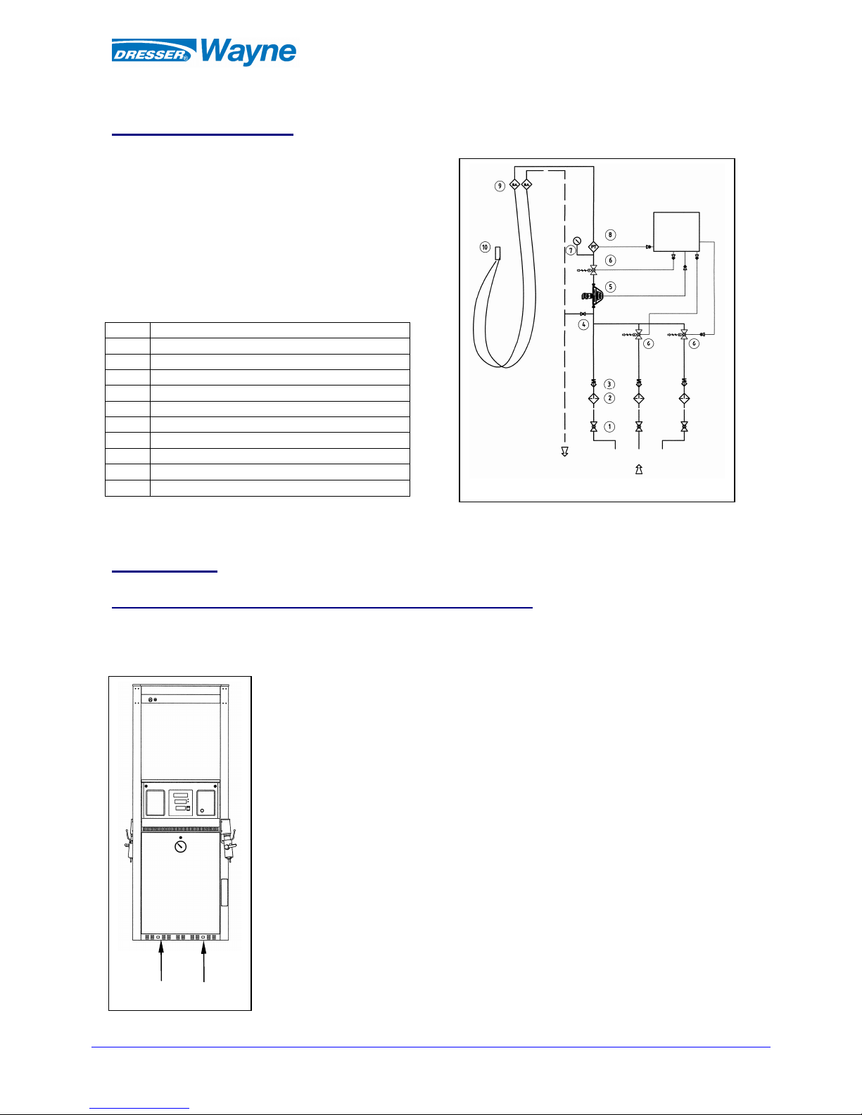
Typical operating diagram
The following diagram illustrates the operating principles of a CNG dispenser with three levels of pressure.
10 Vehicle connection
9 Breakaway device
8 Pressure transmitter
7 Pressure gauge
6 Valve
5 Meter
4 Vent valve
3 Check valve
2 Filter
1 valve (optional)
Pos. Denomination
START-UP
Transportation, unpacking and handling internal components
During transportation the dispenser must be handled with care. Please follow the
instructions on the packaging at all times.
When lifting with forklift trucks lift on the areas indicated with the arrows in this
diagram (areas are about 50 cm one from the other).
Always use the proper methods to lift and transport the dispenser. Non-compliance
with the instructions for moving the dispenser could cause serious damages to
things and people.
Once you have received the dispenser, carefully inspect the equipment to ensure
that it has not been damaged during transportation. Any damaged equipment must
be sent back to the shipper.
While unpacking, make sure not to damage the painted surfaces.
Do not remove the film that protects the dispenser’s lining before it is completely
installed. However, it must be removed immediately after installation to ensure an
easy removal that will not damage painted surfaces. Use proper products (avoid
harmful solvents) to eliminate any glue residues.
Computing
head
Page 9
© Copyright
2008-03-20 V0 Rev.01.0
- 9 - WT004139
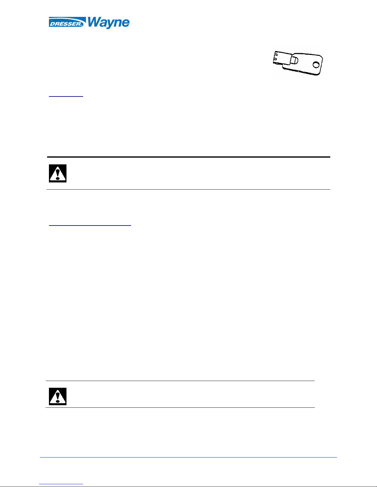
To access internal components for installation and ordinary maintenance, use
the proper key supplied with the dispenser to open lower front panels and/or the
head box.
Installation
Before installing the dispenser, it is necessary to ensure that installation is carried out exclusively by qualified
technicians that are fully knowledgeable about both installation procedures as well as about prevailing
applicable regulations.
All equipment must be installed in compliance with the requirements of the applicable regulations.
In many countries there are norms on safety distance that must be carefully followed. It is necessary to
ensure that these norms are respected, starting from the planning project of the system.
In Italy, the connection of the dispenser to the gas adduction line must take place through an excess flow
valve.
Dresser cannot be held responsible for any damages to persons and/or things deriving
from an improper installation of the dispenser.
When installing, it is necessary to pay particular attention to the following aspects.
Electrical system and safety
Install an emergency stopping system (normally composed of an emergency button and one or more safety
switches) that is capable of interrupt the flow to the equipment in case of operating problems. The emergency
stopping system, not included with the dispenser, must comply with national regulations (for example EN
60204-1). The safety device must be placed in the gas station in order that it is easily accessible to
attendants. Following an emergency stop, the emergency button must be reset before returning back power
to the station.
Returning power must not cause an automatically start of the fuelling.
Ensure that all station attendants fully know where the emergency system is located and how it works.
To install the CNG dispenser, perform the following operations:
• open front panels;
• place and fasten the dispenser on the base;
• make hydraulic connections and check the fastening on the dispenser’s connections;
• connect electrical wiring, checking electrical values;
• power the dispenser;
• open the gas inlet valve;
• open the air/instrument valve (6 / 8 bar);
• close front panels;
In order to properly make hydraulic and electrical connections, always refer to the diagrams supplied by
Dresser.
During transportation the dispenser’s hydraulic connections may loosen. Check whether all
the dispenser’s connections are tight. Always verify that the dispenser or, more generally, the
whole system has no gas leaks.
Page 10

© Copyright
2008-03-20 V0 Rev.01.0
- 10 - WT004139
Page 11

© Copyright
2008-03-20 V0 Rev.01.0
- 11 - WT004139
Page 12

© Copyright
2008-03-20 V0 Rev.01.0
- 12 - WT004139
Page 13

© Copyright
2008-03-20 V0 Rev.01.0
- 13 - WT004139
Page 14

© Copyright
2008-03-20 V0 Rev.01.0
- 14 - WT004139
Page 15

© Copyright
2008-03-20 V0 Rev.01.0
- 15 - WT004139
Page 16

© Copyright
2008-03-20 V0 Rev.01.0
- 16 - WT004139
Initial start-up
Initial start-up is needed to verify whether the dispenser is in perfect operating condition.
Before starting the dispenser, ensure that all installation procedures have been properly carried out (hydraulic
connections, sealing of the fittings, electrical connections, etc.).
Make sure that the junction boxes are properly closed and that all cable glands are accurately fastened.
The junction boxes must not present any signs of openings; any holes not intended for the cables must be
closed with original plugs.
The first start-up of the CNG dispenser must be performed by properly trained personnel. To install the CNG
dispenser, follow the procedure below:
• Switch dispensing selector to the OFF position;
• Power the dispenser complying with the values listed on the corresponding electrical schemes;
• Switch dispensing selector to the ON position;
• Place the hydraulic circuit under pressure and ensure there are no leaks on the hydraulic
connections;
• Switch the dispensing selector to the OFF position;
• Clean the dispenser (minimum delivery of 10 m3 of gas) by dispensing some gas following the
procedure indicated in the following paragraph;
• Check the meter’s calibration by dispensing gas a few times and comparing the measurements
given by the electronic head with those given by a proper sampling instrument (For Example:
precision scale);
Dispensing procedure
To dispense CNG, follow these procedures:
• remove the nozzle from its housing;
• connect the nozzle to the vehicle’s tank or to a test tank (suitable for storing natural gas at the
maximum fuelling pressure);
• bring the three-way valve to the «ON» position (dispensing);
• start dispensing by activating the dispensing selector switch (bring it to the «ON» position);
• the dispenser manages the end of delivery and the stop appears when a pre establish value of
pressure or low flow is reached;
• after stop switch the dispensing selector to the «OFF» position;
• bring the three-way valve to the «VENT» position (no dispensing);
• remove the nozzle from the vehicle’s tank or from the test tank;
• re-insert the nozzle in its housing;
Note 1: the three-way valve can be integrated onto the nozzle or separated.
Note 2: a light signal always indicates the operating status of the dispenser (green= dispenser
ready; red= dispenser fuelling or in error)
Note 3: Pay attention to activate the selector switch only after the three way valve is ON position.
Page 17

© Copyright
2008-03-20 V0 Rev.01.0
- 17 - WT004139
9
10
11
8
12
17
18
19
COMPONENTS
This section briefly describes the main components of a CNG dispenser. The components can be divided into
three groups: external components, hydraulic components and electrical components.
External components
1. Lower front panel
2. Column
3. Nozzle Housing
4. Computing Head Housing
5. Cover
6. Base
7. Id plate
Hydraulic components
8. Manual ball valve
9. Particulate filter
10. Check valve
11. Mass –flow meter
12. Motorized valve
13. Pressure gauge
14. Delivery hose
15. Delivery Nozzle
16. Breakaway Device
Electrical components
17. Electronic head
18. Pressure transmitter
19. Junction box
1
3
2
5
6
7
4
13
14
16
15
Page 18

© Copyright
2008-03-20 V0 Rev.01.0
- 18 - WT004139
HYDRAULIC COMPONENTS
Manual ball valve
The manual ball valve is on the dispenser inlet and prevents the entrance of natural gas in the dispenser itself
during any maintenance operations.
This valve is normally installed on a system when a dispenser is also installed.
Particulate filter
The particle filter is on each inlet line of the dispenser and its function is to separate any solid particles from
the compressed natural gas in order to optimize gas flow and avoid particle deposits in the internal
components.
Check valve
The check valve’s function is to prevent gas flow in the opposite direction of dispensing.
Mass-flow meter
The CNG dispensers are equipped with mass-flow meters that rely on the Coriolis effect. The mass-flow
meter measures the quantity of gas dispensed and communicates with the electronic head.
Coriolis effect: a force apparently due to the speed of rotation of a non-inertial reference system
compared to an inertial reference system; it is equal and opposite to the product of the mass of
particles on which it acts and the relative Coriolis acceleration
For operating characteristics and more information regarding the mass-flow meter, refer to the specific
technical manuals.
Motorized valve
The motorized valve includes a ball valve, a solenoid and a pneumatic actuator.
When the dispensing selector is switched to the ON position (dispensing), the head sends a command to the
solenoid, which activates the inlet of compressed air into the actuator through the inlet door; at this point the
ball valve opens and the gas starts to flow.
The motorized valve returns to its initial position when the head sends the inverse command to the solenoid,
which activates the inlet of compressed air through the outlet door; in this case the ball valve closes and the
flow of the gas stops.
Pressure gauge
The CNG dispenser has a pressure gauge with a scale division from 0 to 400 bar, which allows a constant
monitoring of gas pressure.
Delivery hose
The CNG dispenser’s filling hoses are specifically designed and manufactured to supply natural compressed
gas.
The hoses are wear proof and are high-performance.
There are twin hoses for dispensing and venting.
Standard hoses have an internal diameter of ¼ inch (standard flow) or ½ inch (high flow)
Delivery Nozzle
The CNG dispenser has nozzles capable of satisfying all the requisites of efficiency and safety related to
CNG fuelling.
Generally there are two types of nozzles, for light vehicles (used to fuel automobiles, vans and small trucks)
or nozzles for heavy vehicles (used to fuel buses and trucks). However, there are different nozzles, according
to the characteristics required by different CNG systems (Italy type, NGV1 type, NGV2 type etc).
Page 19

© Copyright
2008-03-20 V0 Rev.01.0
- 19 - WT004139
Three-way valve
The three-way valve is a ball valve which allows gas to flow from the CNG to the vehicle tank.
This valve works according to three different positions:
• OFF position prevents gas flow (no dispensing);
• ON position allows gas flow (dispensing);
• VENT position allows gas to vent from the nozzle;
When the three-way valve is in the vent position, the nozzle can be removed from the CNG vehicle in total
safety.
The three-way valve can be integrated on the connector (standard NGV1 and NGV2).
It is important to place the three-way valve in the vent position before connecting the nozzle to
the tank
Breakaway Device
The CNG dispenser is equipped with breakaway devices capable of immediately interrupting the gas flow if a
vehicle that is being fuelled should move with the nozzle still connected to the tank.
This safety device interrupt gas flow and hence prevents damages to persons, the dispenser and the vehicle.
ELECTRICAL COMPONENTS
Electronic head
Description
The CNG dispenser is equipped with a Dresser electronic head which guarantees high performance in
calculating and constantly monitoring all the operations carried out by the dispenser.
The head, designed specifically to manage CNG dispensers, performs the following operations:
• management and control of the valves and sensors in the dispenser (meters, transducers, etc);
• calculation and display of fuel-related prices and weights;
• management of devices indicating the status of the dispenser (signal lights);
• interfacing with any POS System;
Operation
After having received the signals/values from the mass-flow meter (or any other sensors) the head performs
the following operations:
• controls the CNG fuelling procedure;
• shows fuelling data on the LCD displays;
The electronic head, used on different types of CNG dispensers, can work in four different modes:
• single level mode;
• multi level mode (cascade system);
The data displayed is:
• total price;
• volume supplied, displayed in «kg» or «m3» according to the chosen configuration;
• unit price;
Page 20

© Copyright
2008-03-20 V0 Rev.01.0
- 20 - WT004139
Configuration parameters
The proper functioning of the head is guaranteed by programming a series of configuration parameters,
divided into two groups:
• accessible parameters;
• non-accessible parameters (protected by a metric seal);
To set these parameters it is necessary to use the four buttons on the display.
The final part of the manual indicates the operating procedures to change prices and define the operating
modes of the dispenser.
For all other functions refer to the specific manual of the head.
Error conditions
During operation, the head performs a constant error diagnostic. Once an error is identified, the head:
• immediately stops fuelling (blocking condition);
• lights a red led;
• shows the error code corresponding to the identified error on the unit price display;
When an error is identified during fuelling, the unit price displays the «bloc» message and the error code is
displayed only after the dispensing selector is turn to OFF.
Electrical components used in hazardous areas
The dispenser can be used in potentially explosive areas due to the presence of gas.
The whole dispenser is marked CE/ATEX as a device of group II, category 3 G even in compliance with
prEN13638.
For safety, the electrical system uses single components (junction boxes, meter, pressure transmitter,
electro-valves, etc.) suitable for group II, category 2 G.
MAINTENANCE
The dispenser leaves the factory only after passing accurate tests (hydraulic and electrical). A correct
installation and use should guarantee proper functioning.
In any case, in order to maintain the dispenser’s optimal conditions in time and guarantee its safety, the
station manager must check the components listed in the table below periodically.
Component Intervention
Pneumatic actuator Periodically replace all gaskets and piston slides; check cylinder wear
Electronics and measuring tube Perform measuring tests during official inspections
Filter Disassemble the filter and clean filtering element or replace it if
damaged
Delivery hose Replace if damaged
Three-way valve Check sealing of gaskets and replace if damaged
Check valve Check sealing
Vent valve Check sealing of gaskets and replace if damaged
Gas inlet valve Check sealing of gaskets and replace if damaged
The operational life of these components depends of different conditions such as, for example, the quality of
the product being dispensed, environmental characteristics, climatic conditions and method of use.
The periodicity of maintenance operations must be established as a consequence.
Maintenance operations must be performed exclusively by qualified technicians, trained for this purpose.
Maintenance operators will have to use all personal safety protection (proper shoes, gloves and glasses, etc).
Maintenance operators must be knowledgeable of all measures to adopt in order to prevent any explosive
reaction in the presence of gas (for example, avoid naked flames, sparks, and electrostatic discharge).
Page 21

© Copyright
2008-03-20 V0 Rev.01.0
- 21 - WT004139
Relieving pressure from the dispenser
Before intervening on any hydraulic component, it is necessary to completely discharge pressure from the
gas system in the dispenser as follows:
• close the cut-off valve (ball valve at dispenser inlet);
• open ball valve on the actuator with the manual command on the solenoid valve;
• open the vent valve to discharge gas from the dispenser ensuring that all gas completely leaves
the system;
• at this point it is possible to operate on the hydraulic system ;
• after the intervention, close the vent valve and the ball valve on the actuator and open the ball
valve on the dispenser inlet;
Always remember to disconnect the power supply before operating on the components of the
CNG dispenser.
Cleaning
To clean the dispenser, do not use abrasive detergents or products petrol/petroleum-based products.
Instead, use water with non-aggressive detergents and soft cloths. Adopt all necessary precautions to avoid
any water entering the dispenser.
Before entering the head box, carefully dry any traces of cleaning water. In case of bad weather, make sure
no rain enters the head box. Always remove any snow or ice from the dispenser
.
Disassembling / Scrapping the dispenser
For any reason before disassembling the dispenser, make sure it is completely emptied of any gas. For
transportation, observe all applicable laws. For scrapping, keep with local legislation.
To avoid the risk of electrical shock and/or fire, disconnect all electrical power before
disassembling the dispenser.
Page 22

© Copyright
2008-03-20 V0 Rev.01.0
- 22 - WT004139
OPERATIONAL PROCEDURES ON THE ELECTRONIC HEAD
The GLOBAL VISTA CNG dispenser is equipped with an OTP-ELT electronic head that manages all fuelling
operations and allows the programming of a series of functions.
The display screen, that is the interface between head and user, visualizes the data; the different information
appears on the price, volume and unit price displays.
Changing prices
To change the prices values, press the P0, P1, P2 e P3 programming
buttons on the side of the display.
Press the P1 button to enter in the price change mode.
The price display will show some hyphens, while the volume display will show the pre-established unit price
(for example: 1,235)
------ -----0
1.235 1.235
For example, pressing P0 once and P1 twice, the display will appear as follows:
-----2
1.235
Pressing P0 again, another digit is added on the display and it can be increased or decreased by pressing P1
or P2 respectively.
----20
1.235
The same applies when setting the next digits.
If the new price is set the data can be saved pressing the P3 button. At this point, the volume and price
displays show the data from the last fuelling, while the unit price display shows the new price set.
Using buttons P0, P1 or P2, set new
unit price.
Pressing P0, a zero will appear on the
price display. This value 0 can be
increased with P1 and decreased with
P2
Always use clean and dry hands.
During these operations pay attention to not remove the W&M
seals.
Page 23

© Copyright
2008-03-20 V0 Rev.01.0
- 23 - WT004139
Operational modes of the dispenser
The head can be connected to host equipment for fuelling management.
Operational modes can be set with the P001 parameter.
Values are 0 e 1.
0 = manual mode
1 = automatic mode
Warning, if the dispenser is connected to the Host, it will shift into automatic mode even if it is set
to manual.
Further information
For further information regarding programming, operation and the meaning of certain error codes displayed
by the electronic head, refer to the related manual.
Page 24

© Copyright
2008-03-20 V0 Rev.01.0
- 24 - WT004139
ID PLATE
The GLOBAL VISTA CNG ID plate lists the following information
1 Serial number
2 Year of construction
3 Type of product
4 Space for directions
5 II 3 G (group II surface, category 3, potentially explosive atmosphere due to presence of gas, vapors or
fog)
6 CE marking (in compliance with EMC and ATEX)
7 Epsilon-X marking (in compliance with the ATEX directive)
8 Name and address of the manufacturer
3
1
2
ID PLATE
4
5
6
7
8
Page 25

© Copyright
2008-03-20 V0 Rev.01.0
- 25 - WT004139
DECLARATION OF CONFORMITY
Page 26

© Copyright
2008-03-20 V0 Rev.01.0
- 26 - WT004139
NOTES
_________________________________________________________________________________________
_________________________________________________________________________________________
_________________________________________________________________________________________
_________________________________________________________________________________________
_________________________________________________________________________________________
_________________________________________________________________________________________
_________________________________________________________________________________________
_________________________________________________________________________________________
_________________________________________________________________________________________
_________________________________________________________________________________________
_________________________________________________________________________________________
_________________________________________________________________________________________
_________________________________________________________________________________________
_________________________________________________________________________________________
_________________________________________________________________________________________
_________________________________________________________________________________________
_________________________________________________________________________________________
_________________________________________________________________________________________
_________________________________________________________________________________________
_________________________________________________________________________________________
_________________________________________________________________________________________
_________________________________________________________________________________________
_________________________________________________________________________________________
_________________________________________________________________________________________
_________________________________________________________________________________________
_________________________________________________________________________________________
Page 27

© Copyright
2008-03-20 V0 Rev.01.0
- 27 - WT004139
MARKET & SERVICE
To obtain name and address of the closest authorized maintenance company, please contact:
DRESSER WAYNE
DRESSER Italia S.r.l.
Via Roma 32 - 23018 TALAMONA (SO)
Tel. 0342 608111 - Fax 0342 608299
Page 28

Headquarters
3814 Jarrett Way
Austin, TX 78728
Phone: +1 512.388.8311
Fax: +1 512.388.8302
www.wayne.com
Wayne Sweden
Limhamnsvägen 109
Box 30049
SE-200 61 Malmö
Sweden
Phone: +46 40 360500
Fax: +46 40150381
www.wayne.se
Wayne Brazil
Estrada do Timbo
126-Bonsucesso
Rio de Janeiro, Brazil
Phone: +55-21-2598-7711
Fax: +55-21-2598-7860
Wayne China
1221 Dong Lu Road
Pudong, Shanghai
200135
China
Phone: +8 21-5899-3976
Fax: +8 21-5899-0974
More than a century of experience
Über 100 Jahre Erfahrung
Mer än 100 års erfarenhet
Более, чем столетний опыт работы
Wayne Dresser develops,
manufactures and markets
complete operative systems for
fuel handling at service stations.
Everything from development
and design to efficient production and assembly of components is pursued under one
roof.
Wayne Dresser entwickelt,
produziert und vermarktet
komplette funktionierende
Systeme für die Abgabe von
Kraftstoffen an Tankstellen..
Von der Entwicklung über das
Design bis zur Herstellung und
Installation liefern wir alles aus
einer Hand.
Wayne Dresser utvecklar, tillverkar och marknadsför kompletta operativa system för drivmedelshantering på servicestationer. Under ett och samma tak
ryms allt från utveckling och
konstruktion till rationell tillverkning och sammansättning av
komponenter.
Wayne Dresser разрабатывает,
производит и продает
совершенные оперативные
системы для торговли топлива
на станциях обслуживания.
Все начиная от разработок и
конструкции до эффективного
производства и сборки
компонентов происходит в
пределах одного предприятия.
Wayne Dresser’s
operations comprise four
interdependent functions:
Die Niederlassungen von
Wayne Dresser umfassen vier
ineinander greifende Bereiche:
Verksamheten omfattar fyra
samverkande delar:
Действия Wayne Dresser
включают четыре
взаимосвязанных
направления:
• Equipment such as petrol
pumps, payment terminals, pointof-sale terminals and service
station operative systems.
• Software for recording and
for internal communication at the
station, as well as between the
station and the oil company,
banks and credit institutes.
• Project design with overall
responsibility to the customer.
• Field service, technical
support and supply of spare parts.
• Ausrüstungen wie
Zapfsäulen, Zahlterminals,
Kassenterminals und
Tankstellensysteme
• Software für Registrierung
und Kommunikation auf der
Tankstelle u. zwischen Station
und Mineralölfirma sowie Banken
und Kreditinstituten.
• Projektgestaltung mit
umfassender Verantwortlichkeit
dem Kunden gegenüber.
• Service, technische Unter-
stützung und Lieferung von
Ersatzteilen.
• Utrustning som
bensinpumpar, betalterminaler,
butiksterminaler och stationsdatorer.
• Programvara för registrering
och kommunikation internt på
stationen samt mellan stationen
och oljebolaget, banker och
kreditinstitut.
• Projektering med totalansvar
gentemot uppdragsgivaren.
• Service på fältet, teknisk
support och reservdelsförsörjning.
• Оборудование, например,
топливораздаточные колонки,
платежные терминалы,
терминалы точек продажи и
системы управления АЗС.
• Программное обеспечение
для регистрации и для
внутренней связи на АЗС, а
также между АЗС и нефтяной
компанией, банками и
институциями кредитов.
• Проектирование с полной
ответственностью к клиенту.
• Обслуживание на местах,
техническая поддержка и
поставка запасных частей.
Wayne Dresser makes it easier
for the motorist to fill up and
make his motoring purchases,
while effectively meeting the
needs of the service station
owner for operating supervision
and for conforming to the
demands of the authorities for
measurement accuracy,
minimising pollution and
ensuring safety.
Wayne Dresser erleichtert dem
Fahrer die Betankung und
damit verbundene Einkäufe,
unterstützt gleichzeitig den
Stationär bei der
übersichtlichen Führung seines
Betriebes unter
Berücksichtigung der
behördlichen Vorschriften
hinsichtlich Messgenauigkeit,
Umwelt- und
Sicherheitsauflagen.
Wayne Dresser gör det lättare
för bilisten att tanka och handla.
Samtidigt tillgodoses stationsägarens krav på en effektiv
driftskontroll och myndighetskraven på mätnoggrannhet,
miljövänlighet och
driftssäkerhet.
Wayne Dresser упрощает
процесс заправки и
приобретения покупок при
эффективном согласовании
потребностей владельца АЗС
для оперативного управления
и для соблюдения требований
государственных и
метрологических служб, а
также уменьшения
загрязнения окружающей
среды и обеспечения
безопасности.
 Loading...