

Page 1
12V Battery
Back-up
Systems
Please read and save these instructions. Read carefully before attempting to assemble, install, operate or maintain the
product described. Protect yourself and others by observing all safety information. Failure to comply with instructions
could result in personal injury and/or property damage! Retain instructions for future reference.
Description
The ESP15 and ESP25 are battery operated
back-up sump pump systems. It does not
replace a regular primary pump. It is
designed to provide protection in the event
gasoline, fuel oil, kerosene, etc. Do NOT use in a
flammable and/or explosive atmosphere. Pump
SHOULD only be used to pump clear water.
Personal injury and/or property damage COULD
result.
household electrical power fails. All wiring MUST be
performed by a
are damaged, call our customer service If the
department at 1-800-237-0987. basement
has water or moisture on the Safety
Guidelines floor, do area until all power is turned NOT walk on wet
This manual contains information that is off. If the shutoff box is in the basement, very
important to know and understand. call an electrician. Remove pump and
This information is provided for SAFETY and to
PREVENT EQUIPMENT PROBLEMS.
To help recognize this information,
either repair or replace. Failure to follow this
warning COULD result in fatal electrical shock.
observe the following symbols. Do NOT
DANGER indicates expose
an imminently battery to sparks or flames as
hazardous situation which, if NOT avoided, an explosion or fire COULD WILL result in death
or serious injury. result.
WARNING indicates Battery
a potentially acid is
hazardous situation which, if NOT avoided, corrosive. Avoid spilling on COULD result in
death or serious injury. skin or clothing. Eye
protection MUST be worn
CAUTION indicates when handling the battery.
a potentially
hazardous situation which, if NOT avoided,
MAY result in minor or moderate injury.
NOTICE indicates
important
information, that if NOT followed, MAY cause
damage to equipment.
General Safety Information clear water.
This pump is NOT designed
CALIFORNIA PROPOSITION
65 to handle effluent, salt
water, brine,
This product or
its laundry
discharge or any other power cord
contains application which MAY contain
caustic
chemicals known to the State of California to cause
cancer and birth defects or other reproductive
harm. Wash hands after handling.
GENERAL SAFETY
chemicals and/or foreign materials. Pump
damage MAY occur if used in these applications
and WILL void warranty.
Battery Requirements
1. Use only a new fully charged 12 V
© 2011, WAYNE/Scott Fetzer Company.
Operating Instructions and Parts Manual
ESP15, ESP25
Unpacking
Inspect this unit before it is used.
Occasionally, products are damaged during
shipment. If the pump or components
qualified electrician. Failure to follow this
warning COULD result in fatal electrical shock.
Page 2
Operating Instructions and Parts Manual
www.waynepumps.com
2
rmation visit www.waynepumps.com
2. Battery sizes that will fit into the battery box are 24C, 24VCM, 27C, 27CM, and 27F.
3. Battery recharge time will be different at each installation. Under normal conditions it will
take two to four days to bring a deep cycle battery back to full charge after it has been
discharged. If electrical power to the house is lost more than once a week, consider keeping
a spare, fully-charged battery to replace an exhausted battery for the back-up sump pump.
Installation – ESP15
Installation of this
unit may take
several hours. Before disabling your main pump, have ready an appropriate means of evacuating the
sump. 1. Turn power to main pump off.
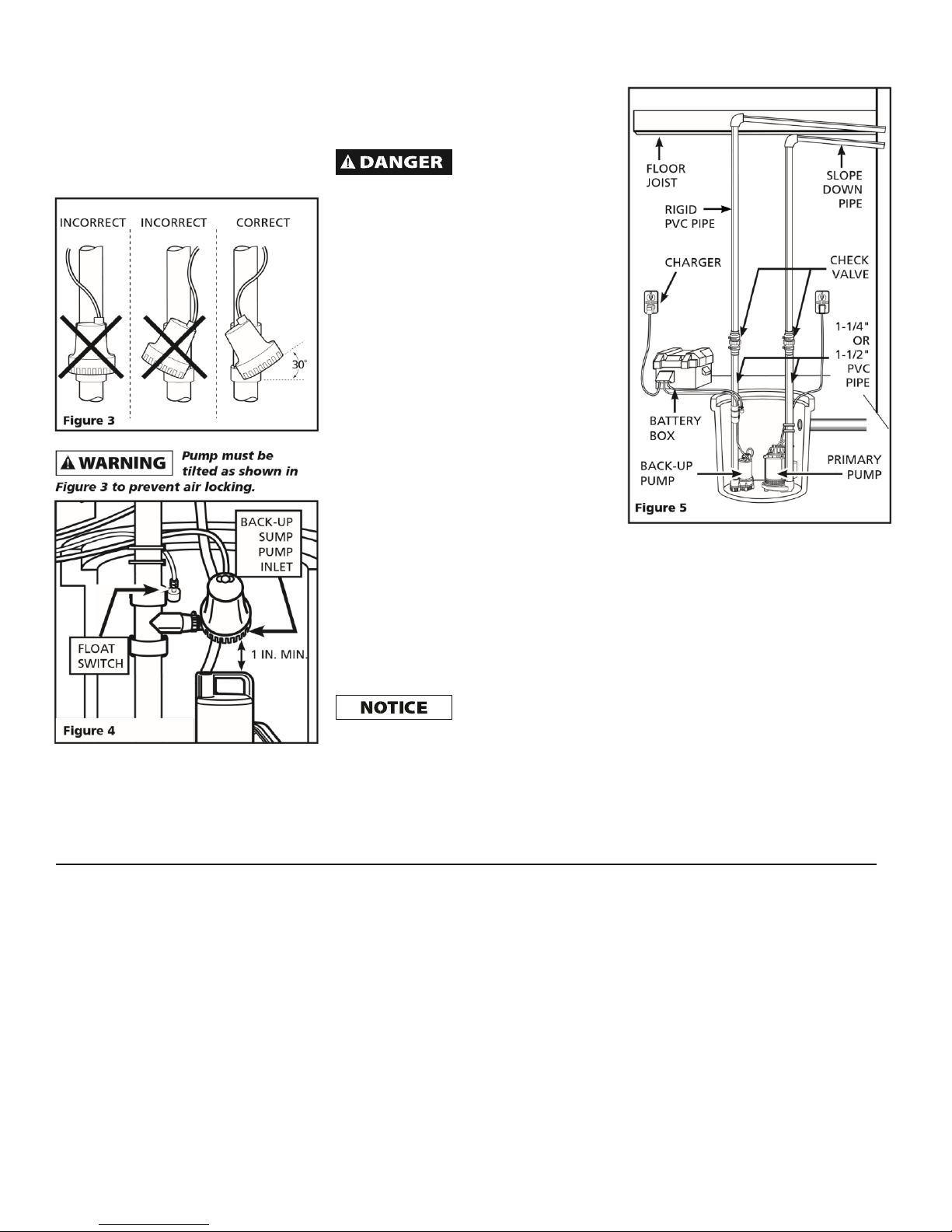
2. Pump must be installed using 1-1/4 in. or 1-1/2 in. rigid PVC piping. A check valve (not
included) must be installed between the ESP’s tee and the main pump (see Figure 1).
LEAVE A 4 IN.
MIN. BETWEEN
BASIN LID
AND
BACK-UP
PUMP
CHECK LEAVE A 1 IN.
VALVE MIN. BETWEEN
BACK-UP AND
PRIMARY PUMP
Figure 1
3. Measure and cut discharge pipe so that back-up pump is a minimum of 1 in. above the main
pump. This will allow main pump to operate normally (see Figure 1).
4. Check the fit of the components
before permanently attaching. Using
354001-001 7/11
Installation - ESP15 (continued)
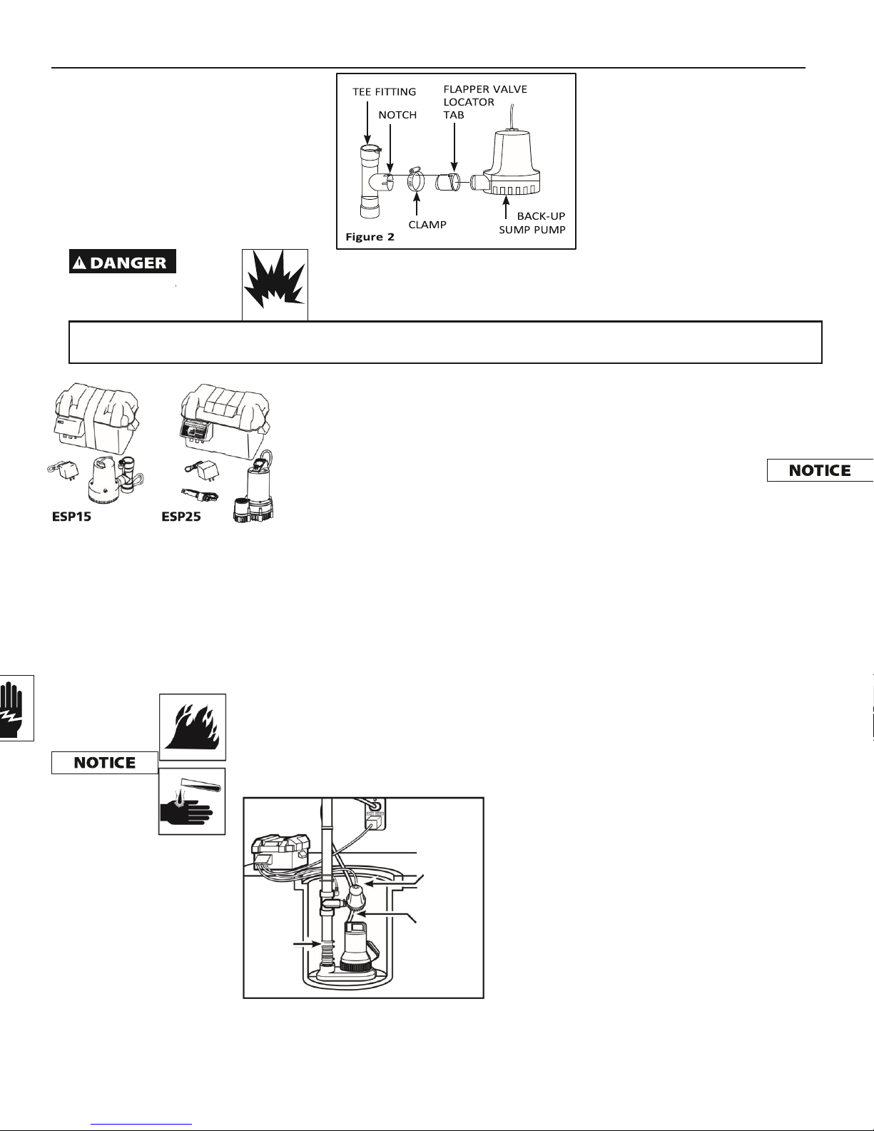
5. Insert flapper valve into tee. Be sure locator
tab is in the notch of the tee fitting (see
Figure 2).
hole, and secure with nut. Make sure
that float switch is above pump base and
that power wires do not interfere with
float switch or pump inlet.
Installation – ESP25
I
n
s
t
a
l
l
a
t
i
o
n
o
f
t
h
i
s
u
n
i
t
m
a
y
t
a
k
e
several hours. Before disabling your main pump,
have ready an appropriate means of evacuating
the sump. 1. Turn power to main pump off.
Do NOT
use to
deep cycle battery. Electrolyte level PVC cement, glue tee in place. Note must be
checked and maintained the up direction arrow on the tee; the
in accordance with manufacturer’s notch must be to the top or flapper guidelines.
valve will not work (see Figure 2).
pump flammable or explosive
fluids such as
REMINDER: Keep your dated proof of purchase for warranty purposes! Attach it to this manual
or file it for safekeeping.
6. Slide clamp onto tee.
7. Insert pump into flapper valve, tilt pump 30˚.
When tilted, the side with
The ESP25 can be installed as a back-up
system with a separate dedicated discharge
line (Method 1), or tied into an existing sump
pump line (Method 2, Page 3).
Page 3
2. Pump must be installed using 1-1/4” or 1-1/2” rigid PVC piping.
PUMP INSTALLATION
the power cord should be up (see Unplug the existing Figure 3).
Tighten clamp around the AC pump. Failure
to
pump and flapper valve (see Figure 2). follow
this warning could result in fatal electrical shock.
1. Verify that the existing AC pump is in
good working order. If the AC pump is
questionable, it is typically recommended that
the unit be replaced with a 1/3 or 1/2 HP pump.
2. Remove any silt or accumulated
debris from the sump pit and surrounding area.
Method 1 (Preferred)
1. Place the back-up pump on a solid,
level surface in the sump pit. Do not place the
pump on a loose or sandy surface. Small stones
or sand may damage the pump resulting in
potential pump failure.
2. This pump has a 1-1/2 in. NPT
discharge. If a 1-1/4 in. discharge pipe is desired,
an adapter (sold separately) will be necessary.
Smaller diameter piping will reduce pump flow,
rate and performance.
3. Cut a 4 ft. section of 1-1/4 in. or 1-1/2
in. diameter rigid PVC pipe. Cement 1-1/4 in.
pipe to a threaded fitting. Cement 1-1/4 in. pipe
into pipe coupling. Attach 1-1/4 in. pipe section
to the ESP25 discharge adapter.
4. Screw PVC pipe onto pump discharge.
Be careful not to
strip or cross thread
plastic fittings or check valves. Flex hose is not
recommended. Rigid PVC or
8. To install float switch
for standby metal pipe is
required for a permanent pump, first slide bracket
into slot on
installation.
top of tee. Secure bracket with screw
provided. Remove top hex nut from 5. Place the pump with the 4’ section of switch
and slide the cord up and out PVC pipe on a solid, level surface in of the way. Slip cord
through slot in the sump pit on an elevated surface.
bracket, pull threaded stud through
6. Attach a rubber check valve (sold
separately) to the top of the discharge pipe.
This will allow the pump or check valve to
be removed easily for servicing. NOTE:
Check valves can be placed directly in the
pump discharge if desired. However, for
ease of disassembly, it is recommended that
check valves be placed above the sump as
shown in Figure 1, page 1.
The remainder of the discharge pipe
installation will vary depending on
individual circumstances. Using sound
plumbing practices, route the discharge
pipe to an exterior wall by the shortest
path. Keep turns to a minimum because
they reduce flow output of the pump. The
pipe that exits the building structure should
be sloped downward so that water will not
freeze in the pipe.
When installing the separate discharge pipe,
drill through the outside wall with
appropriate drilling equipment. Seal the hole
to prevent water from entering.
Method 2
If a separate, dedicated discharge is not
possible as in Method 1, the ESP25 pump
can be tied in to the primary pump’s
discharge pipe by installing a “Y” connector.
Two check valves will be required.
1. Locate the ESP25 on a solid, level
surface in the sump pit. Do not place
the pump on a loose or sandy surface.
Small stones or sand may damage the
pump resulting in potential pump
failure.
Page 4
Operating Instructions and Parts Manual
www.waynepumps.com
4
Installation - ESP25 (continued)
2. This pump has a 1-1/2 in. NPT
discharge. If a 1-1/4 in. discharge pipe
is desired, an adapter (not included)
will be necessary. Smaller diameter
piping will reduce pump flow, rate and
performance.
3. A check valve will be required in the
discharge line of both the Main AC
pump and the ESP25 pump to prevent
recirculation of water into the sump
pit. System will not function without
two check valves.
4. Cut a 4 ft. section of 1-1/4 in. or 1-1/2
in. diameter rigid PVC pipe. Cement 11/2 in. pipe to a threaded fitting.
Cement 1-1/4 in. pipe into pipe
coupling. Attach 1-1/4 in. pipe section
to the ESP25 discharge adapter.
5. Screw on to pump discharge.
Be
careful not to strip or
cross thread plastic
fittings or check valves. Flex hose is not
recommended. Rigid PVC or metal pipe is
required for a permanent installation.
6. Place the pump with the 4’ section of
PVC pipe on the sump floor or on an
elevated surface if required.
7. Attach a rubber check valve (sold
separately) to the top of the discharge
pipe. This will allow the pump or check
valve to be removed easily for
servicing.
RIGID SLOPE
FLOOR
PVC PIPE DOWN PIPE JOIST "Y"
CONNECTOR
45°
ELBOW
CHECK
CHARGER VALVE
1-1/4"
OR
1-1/2"
PVC
PIPE
BATTERY
BOX
BACK-UP PRIMARY PUMP PUMP
Figure 6
8. Duplicate the discharge piping
arrangement for the primary AC pump if
the existing discharge line has to be
adjusted to accommodate a second pump.
9. Glue a 45º elbow to the short pipe on the
ESP25 pump. Glue a “Y” adapter to the
short pipe on the existing pump, as shown
in illustration for Method 2.
10. Glue a short piece of PVC pipe between
the 45º elbow and the “Y”.
NOTE: Check valves can be placed directly in
the pump discharge if desired. However, for
ease of disassembly, it is recommended that
check valves be placed above the sump as
shown in Figure 2, page 2.
The remainder of the discharge pipe
installation will vary depending on individual
circumstances. Using sound plumbing
practices, route the discharge pipe to an
exterior wall by the shortest distance.
Methods 1 and 2
Install float switch at least 10 in.-12 in. above
bottom of sump pit so that backup unit turns
on only when the water level is higher than
the normal “on” level for primary pump. Use
the wire ties provided to secure the switch to
the discharge pipe. Make sure power wires do
not interfere with float switch, pump inlet, or
main pump operation. Backup pump must not
be allowed to run dry.
Control Box Installation – ESP15 &
ESP25
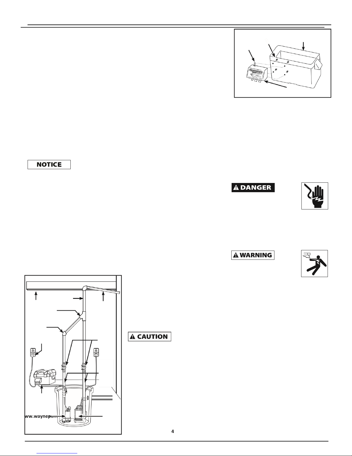
1. Attach control box to the side of battery
box as shown in Figure 7. Place battery in
box, attach red cable to positive battery
post and black cable to negative post. Put
lid on box.
If cables are
reversed, damage to
the control box or battery could result, and
warranty will be void.
2. Place battery box within 6 ft. of the sump
and a 115 VAC separately fused outlet. The
outlet must be protected by a ground fault
circuit interrupter (GFCI). The area must
also be clean, dry and well-ventilated.
3. Plug the float switch, pump, and charger
into the control box. (connections are
marked on the control box).
4. Test pump operation by filling the sump
with water while the main pump is
unplugged. If the pump
3
ESP15, ESP25
CONTROL
BATTERY BOX
LEAD BOX SCREW BOTTOM
WIRE
Figure 7 CONTROL BOX
operates properly, plug the charger into
the GFCI protected outlet to begin
charging the battery.
5. Protect electrical cord from sharp objects,
hot surfaces, oil, and chemicals. Avoid
kinking the cord and replace damaged
components immediately.
Operation
ALWAYS
disconnect the power source
before attempting to install,
service, relocate or maintain the
pump. NEVER touch sump pump, pump motor,
water or discharge piping when pump is connected
to electrical power. NEVER handle a pump or pump
motor with wet hands or when standing on wet or
damp surface or in water. Fatal electrical shock
COULD occur.
Risk of
electrical shock! This pump is
supplied with a grounding
conductor and grounding type
attachment plug. Use a grounded receptacle to
reduce the risk of fatal electrical shock. NEVER cut
off the round grounding prong. Cutting the cord or
plug will void the warranty and make the pump
inoperable.
1. With a fully charged battery, test Back-up
Pump operation by filling the sump with
water while the primary pump is
unplugged. If the Back-up Pump operates
properly, plug the charger into the GFCI
protected outlet and the primary pump
into a separate GFCI outlet.
2. After installation, the standby pump will
start when the water level rises above
the depth that the primary pump should
start.
3. The control box has a DC charger
designed to shorten the recharging time
of your battery, and to prevent
overcharging. In addition, the control box
has a time delay which keeps the pump
Page 5

from repeated, short cycles when it shuts
off. This time delay feature will allow the
pump to run 20-25 seconds after the
switch reaches the off position.
www.waynepumps.com
Operation (continued)
4. The control box contains a multicolored
indicator light. When AC power is
present, the light will indicate the
charging state, and not reflect actual
battery voltage, particularly with a
defective battery. In order for the
indicator light to provide an accurate
reading, steps “a” through “d” must be
followed. a. Unplug primary AC pump and
the charger--a power off alert tone will
sound for 30 seconds.
b. Lift and release the float switch to
activate the back-up pump.
c. When the back-up pump stops, read
the test light:
Green: Indicates battery is
charged.
Yellow: Voltage is low,
indicating battery is partially
charged.
Red: Battery is completely
discharged or defective.
d. Plug in charger and main AC pump.
When AC power is out, and when pump
has been running, the light will indicate
battery status.
5. A chirping sound from the control box
will accompany the red light, indicating
that the battery may require attention or
replacement. Voltage is only an indicator
of battery condition and may not reflect
the true condition of the battery. See
Maintenance for instructions on
assessing battery condition.
6. A single 30-second tone will sound when
power to the system is interrupted. The
unit will reset automatically when power
is restored. A 3-second tone will sound
every time the pump starts.
Maintenance
ALWAYS
disconnect the electrical supply
before attempting to install,
service, relocate or perform any
maintenance. If the power source is out of sight,
lock and tag in the open (off) position to prevent
unexpected power application. Failure to do so
could result in fatal electrical shock. Only qualified
electricians should repair this unit. Improper repair
could result in fatal electrical shock.
1. Once a month, check battery condition.
2. Unplug the wall charger.
3. For batteries with top caps that can be
removed, the electrolyte level should be
checked and filled to manufacturer’s
specifications. The charge for each cell
should be checked with a hydrometer. A
specific gravity of 1.265 indicates the
battery is at full charge. If the specific
gravity of any of the cells varies more
than .050, the battery should be
replaced.
NOTE: An inexpensive hydrometer can
be purchased at an automotive parts
dealer.
4. Inspect the terminals and clamps for
corrosion and tightness. Clean and
tighten as required.
5. Unplug the main pump and fill sump
with water until back-up pump turns on.
Repeat process two times to be sure
pump is operating normally.
6. If pump operates normally, plug charger
into wall outlet, turn on main pump. If
pump fails to operate normally, see
Troubleshooting chart and correct
problem. Repeat step 5. BATTERIES
Dangerous hydrogen
gas can be released
from batteries while charging. Sparks can ignite
the gas in an enclosed space. Wear safety
goggles when connecting batteries. Battery
connections should be made in a well-ventilated
area.
Troubleshooting Chart - Back-up Pump
Symptom(s)
Possible Cause(s)
Corrective Action(s)
Pump will not run
1. Connections not secure
2. Low battery
3. Float switch obstruction
4. Defective or blown fuse
1. Check all connections
2. Check battery and replace if low
3. Make sure nothing is interfering with the operation of the switch
4. Check internal fuse located inside the control box. Pull the charger from the wall outlet
and remove. If the fuse is blown, replace it with a 15 amp automotive type fuse
Motor hums but
pump won’t run
1. Defective battery
2. Obstructed impeller
1. Check battery and replace if low or defective
2. Unplug pump and check to see if impeller is free to turn. If impeller is locked, remove the 4
screws on the bottom of the pump to release the housing around the impeller. Remove
the obstruction. Reassemble pump and reconnect
Pump runs but
pumps very little or
no water
1. Check valve missing or improperly
installed
2. Obstruction in discharge pipe
3. Pump not rotated 30˚
4. Pump air locked
5. Discharge pipe length and / or height
exceeds capacity of pump
6. Low or defective battery
1. Check to make sure a check valve is installed and functioning between primary pump
discharge and standby sump pump tee fitting
2. Check for obstruction and clear if necessary
3. Check that pump is rotated 30˚ in tee fitting in ESP15 Installation section, Figure 3, on page
2
4. The impeller housing has a small hole on its side. This hole must be open for the pump to
prime. With the pump unplugged, remove the 4 screws on the bottom of the pump to
release the housing around the impeller. Clean out the hole and replace cover
5. If discharge is too high, a separate line may be required with a lower discharge height
6. Check battery and replace if low or defective
Pump cycles too
frequently
1. Main check valve located between the 1. Install check valve or repair as required
discharge of the primary pump and the back-up sump pump tee fitting or the back-up
sump pump flapper valve not installed or working properly
Page 6
Operating Instructions and Parts Manual
www.waynepumps.com
6
Maintenance (continued)
Working in the
vicinity of lead acid
batteries can be dangerous. Before making
connections or servicing the batteries, read and
follow instructions in all applicable instruction
manuals. To reduce the risk of battery
explosion, follow the instructions in this manual
and those published by the battery
manufacturer, as well as those of any other
equipment used in the surrounding area.
If battery acid
contacts your eye(s),
flush with cold running water for 10 minutes and
seek immediate medical attention. If acid contacts
your skin or clothing, wash immediately with soap
and water.
Never smoke or allow a
spark or
flame in the vicinity of the battery.
ESP15, ESP25
Avoid dropping
metal tools on the battery
posts because they may spark or short-circuit the
system or battery, causing an explosion.
Follow battery manufacturer’s maintenance
procedures and schedules. Be certain that the
area around the batteries is well ventilated.
Before servicing the batteries, blow away
gasses by waving a piece of cardboard near
the batteries.
For Replacement Parts, call 1-800-237-0987
Please provide following information:
- Model number
- Serial number (if any)
- Part description and number as shown in parts list
Address parts correspondence to:
WAYNE Water Systems
101 Production Drive
Harrison, OH 45030 U.S.A.
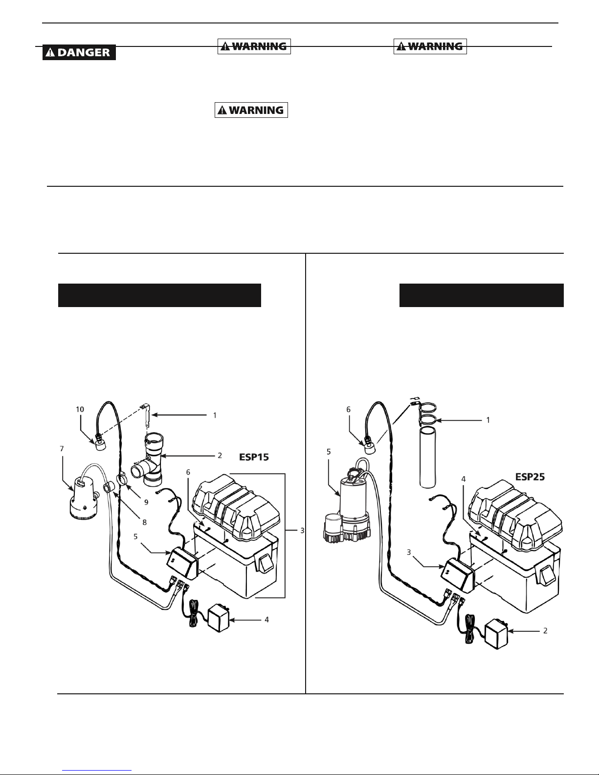
Repair Parts List – ESP15
Repair Parts List – ESP25
Ref.
No. Description Part Number Qty
Ref.
No. Description Part Number Qty
1 Bracket 46049-001 1
2 Tee fitting 17233-002 1
3 Battery box 23217-001 1
4 Charger 17220-004 1
5 Control box 30209-003 1
6 Screw control box 16119-002 4
7 Pump 17218-003 1
8 Flapper valve 17216-001 1 9
Clamp hose 16044-001 1
10 Float switch 30033-001 1
1 Bracket 46049-001 1
2 Charger 30221-001 1
3 Control box 30222-004 1
4 Screw control box 16119-002 4
5 Pump 58324-001 1
6 Float switch 30033-001 1
Page 7

www.waynepumps.com
5
ESP15, ESP25
LIMITED WARRANTY
System ESP15: For one (1) year from the date of purchase, WAYNE Water Systems ("WAYNE") will repair or replace, at its option, for the original
purchaser any part or parts of its Sump Pumps or Water Pumps (“Product”) found upon examination by WAYNE to be defective in materials or
workmanship.
System ESP25: For two (2) years from the date of purchase, WAYNE Water Systems ("WAYNE") will repair or replace, at its option, for the original
purchaser any part or parts of its Sump Pumps or Water Pumps (“Product”) found upon examination by WAYNE to be defective in materials or
workmanship.
Please call WAYNE (1-800-237-0987) for instructions or see your dealer. Be prepared to provide the model number and the serial number
when exercising this warranty. All transportation charges on Products or parts submitted for repair or replacement must be paid by
purchaser.
This Limited Warranty does not cover Products which have been damaged as a result of accident, abuse, misuse, neglect, improper installation,
improper maintenance, or failure to operate in accordance with WAYNE’s written instructions.
THERE IS NO OTHER EXPRESS WARRANTY. IMPLIED WARRANTIES, INCLUDING THOSE OF MERCHANTABILITY AND FITNESS FOR A PARTICULAR
PURPOSE, ARE LIMITED TO ONE (1) YEAR FROM THE DATE OF PURCHASE ON SYSTEM
ESP15 AND TWO (2) YEARS FROM THE DATE OF PURCHASE ON SYSTEM ESP25. THIS IS THE EXCLUSIVE REMEDY AND ANY LIABILITY FOR ANY
AND ALL INDIRECT OR CONSEQUENTIAL DAMAGES OR EXPENSES WHATSOEVER IS EXCLUDED.
Some states do not allow limitations on how long an implied warranty lasts, or do not allow the exclusions or limitations of incidental or
consequential damages, so the above limitations might not apply to you. This limited warranty gives you specific legal rights, and you may also
have other legal rights which vary from state to state.
In no event, whether as a result of breach of contract warranty, tort (including negligence) or otherwise, shall WAYNE or its suppliers be
liable for any special, consequential, incidental or penal damages including, but not limited to loss of profit or revenues, loss of use of the
products or any associated equipment, damage to associated equipment, cost of capital, cost of substitute products, facilities, services or
replacement power, downtime costs, or claims of buyer’s customers for such damages.
You MUST retain your purchase receipt along with this form. In the event you need to exercise a warranty claim, you MUST send a COPY of the
purchase receipt along with the material or correspondence. Please call WAYNE (1-800-237-0987) for return authorization and instructions.
DO NOT MAIL THIS FORM TO WAYNE. Use this form only to maintain your records.
MODEL NO. (PRIMARY PUMP) _______________________ MODEL NO. (BACK-UP PUMP) _______________________ SERIAL NO.
(PRIMARY PUMP) _______________________ SERIAL NO. (BACK-UP PUMP) _______________________ INSTALLATION DATE
__________________ ATTACH YOUR RECEIPT HERE
Page 8
Operating Instructions and Parts Manual
www.waynepumps.com
8
Systèmes de
secours par
batterie de 12V
Veuillez lire et conserver ces instructions. Lire attentivement avant de commencer à assembler, installer, faire fonctionner
ou entretenir l'appareil décrit. Protégez-vous et les autres en observant toutes les informations sur la sécurité. Négliger
d'appliquer ces instructions peut résulter en des blessures corporelles et/ou en des dommages matériels! Conserver ces
instructions pour références ultérieures.
Instructions d'Utilisation et Manual de Pièces
ESP15, ESP25
Description
ESP15 et ESP25 sont des systèmes de pompe
de puisard de secours fonctionnant sur
batterie. La pompe de secours ne remplace
pas la pompe principale. Elle est conçue pour
fournir la protection contre les pannes
d’électricité domestiques.
Déballage
Vérifiez cette unité avant de l’utilisation.
Parfois, un produit peut être endommagé
pendant le transport. Si la pompe ou les
composants sont endommagés, appelez
notre service à la clientèle au 1-800-237-
0987.
Directives De Sécurité
Ce manuel contient de l’information très
importante qui est fournie pour la SÉCURITÉ
et pour ÉVITER LES PROBLÈMES
D’ÉQUIPEMENT. Rechercher les symboles
suivants pour cette information.
DANGER indique
une situation
hasardeuse imminente qui RÉSULTERA en perte
de vie ou blessures graves.
AVERTISSEMENT
indique une situation
hasardeuse potentielle qui PEUT résulter en perte
de vie ou blessures graves.
ATTENTION indique
une situation
hasardeuse potentielle qui PEUT résulter en
blessures.
AVIS indique de
l’information
importante pour éviter le dommage de
l’équipement.
Généralités Sur La Sécurité
PROPOSITION 65 CALIFORNIE
Ce produit ou son
cordon peuvent
contenir des produits chimiques qui, de l’avis de
l’État de Californie, causent le cancer et des
anomalies congénitales ou autres problèmes de
reproduction. Lavezvous les mains après la
manipulation.
GÉNÉRALITÉS SUR LA SÉCURITÉ
utiliser dans un atmosphère inflammable et/ou
explosif. La pompe devrait être utilisée pour le
pompage de l’eau claire seulement, sinon, il y a
risque de blessures personnelles et/ou dégâts
matériels.
Toute installation
des fils DOIT être
effectuée par un électricien qualifié. Manque de
suivre cet avertissement PEUT résulter en secousse
électrique mortelle.
NE
PAS
marcher
sur un plancher de sous-sol
trempe ou humide avant de
couper l’électricité. Si la boîte de branchement est
dans le sous-sol, contacter un électricien. Enlever
la pompe et la réparer ou remplacer. Manque de
suivre cet avertissement peut résulter en secousse
électrique mortelle.
NE PAS
exposer
la pile à des étincelles ou des
flammes. Une explosion ou un feu
PEUT y résulter.
L’acide
de pile
est corrosive. NE PAS le renverser
sur la peau ni sur les vêtements.
La protection oculaire doit être
usure en contrôlant la batterie.
Un clapet DOIT être
utilisé sur le décharge de
la pompe de puisard principale (voir Figure 1).
Un interrupteur pour
protéger contre un
défaut de mise à la terre (DDFT) est exigé.
Cette pompe est
conçue pour le pompage
de l’eau claire SEULEMENT. Cette pompe N’EST
PAS conçue pour les substances qui contiennent
les produits chimiques caustiques et/ou les
matières étrangères tels que l’eau salée, la
saumure, le décharge de buanderie. L’utilisation
de ces produits POURRAT endommager la pompe
et NIERA la garantie.
Exigences de la Batterie de la
Pompe de Secours
doit être vérifié et entretenu selon les
directives du fabricant.
2. La boîte de batterie accomode les
batteries de tailles 24C, 24VCM, 27C,
27CM et 27F.
3. Le temps pour recharger les batteries
varie avec chaque installation. Dans des
conditions normales, la recharge
complète des batteries de décharge
profonde nécessitera entre deux et
quatre jours après qu’elle soit
déchargée. S'il y a une panne de courant
dans la maison plus d'une fois par
semaine, considérez avoir une pile de
rechange, bien chargée pour remplacer
la pile épuisée de la pompe de décharge
de secours.
Installation – ESP15
L’installation de ce
NE PAS
pomper
Utiliser seulement des nouvelles piles de 12 V
complètement chargées à fonctions
décharge profonde. Le niveau
d’électrolyte
de 1 po au dessus de la pompe
principale. Ceci permettra la pompe
principale de fonctionner normalement
(voir Figure 1).
les fluides explosifs tels que
l’essence, l’huile à chauffage, le
kérosène etc. NE PAS
MÉMENTO: Gardez votre preuve datée d'achat à fin de la garantie! Joignez-la à ce manuel ou
classez-la dans un dossier pour plus de sécurité.
Page 9

modèle pourrait
durer plusieurs heures. Vous devez d’avoir une
méthode alternative fiable disponible pour vider
le puisard après le démontage de la pompe
principale.
1. Couper la puissance à la pompe
principale.
2. Installer la pompe en utilisant de la
tuyauterie rigide CPV 1-1⁄4 po ou 1-1⁄2
po. Un clapet (Vendu séparément) doit
être installé entre le T du modèle ESP et
la pompe principale (voir Figure 1).
LAISSER UN
ESPACE DE 10 CM
(4 PO.) AU MIN ENTRE
LE COUVERCLE
DE LA CUVE ET
LA POMPE
DE SECOURS
LAISSER UN ESPACE
DE 2,5 CM (1 PO.)
CLAPET AU MINIMUM
ENTRE LA POMPE
DE SECOURS ET LA
POMPE PRINCIPALE
Figure 1
3. Mesurer et couper le tuyau de décharge
afin que la pompe de sauvegarde soit un
minimum
354001-001 7/11
© 2011, WAYNE/Scott Fetzer Company.
7 Fr
Page 10

Instructions d'Utilisation et Manual de Pièces
10 Fr
Installation – ESP15 (suite)
4. Vérifier l’ajustage des pièces avant de les
fixer en permanence. Coller le T en place
avec du ciment CPV. L’encoche doit être
vers le haut, sinon la soupape à clapet ne
fonctionnera pas (Figure 2).
5. Introduire la soupape à clapet dans le T.
S’assurer que la languette indicatrice soit
dans l’encoche du T (voir Figure 2).
6. Glisser le collier sur le T.
7. Introduire la pompe dans la soupape à
clapet, incliner la pompe 30˚, le cordon
d’alimentation devrait être face en haut
(voir Figure 3). Serrer le collier autour de
la pompe et la soupape à clapet (voir
Figure 2).
8. Pour installer l’interrupteur à flotteur
d’une pompe de secours, glisser d’abord
la sangle latérale dans la fente sur le
dessus du T. Fixer avec la vis fournie.
Retirer l’écrou hexagonal supérieur de
l’interrupteur et glisser vers le haut le
long du cordon et de côté. Glissez le
cordon par la fente de la sangle, tirer le
goujon fileté par le trou et fixer avec
l’écrou. S’assurer que l’interrupteur à
flotteur est audessus de la base de la
pompe et que les fils de courant
n’entrave pas le fonctionnement de
l’interrupteur à flotter ou l’entrée de la
pompe.
Installation – ESP25
L’installation de
ce modèle pourrait
durer plusieurs heures. Vous devez d’avoir une
méthode alternative fiable disponible pour vider le
puisard après le démontage de la pompe
principale.
1. Couper la puissance à la pompe
principale.
2. Installer la pompe en utilisant de la
tuyauterie rigide CPV 1-1/4 po ou
1-1/2 po
INSTALLATION DE LA POMPE
Le ESP25 peut être installé comme système de
secours avec une conduite de décharge
distincte (Méthode 1) ou relié à une conduite
de pompe de vidange (Méthode 2, page 11).
Débrancher la pompe de
c.a.
actuelle. Ne pas suivre cet avertissement pourrait
mener à un choc électrique mortel.
1. Vérifier que la pompe de c.a. actuelle soit
en bon état. Si la pompe de c.a. est dans
un état douteux, il est recommandé
normalement de la remplacer avec une
pompe de 1/3 ou de 1/2 HP.
2. Retirer tout débris accumulé ou vase des
environs et du puisard.
MÉTHODE 1 (DE CHOIX)
1. Placer la ESP25 sur une surface solide,
à niveau dans le puisard. Ne pas placer
la pompe sur une surface meuble ou
de sable. De petites pierres ou le sable
peuvent endommager la pompe
menant à une défaillance de pompe
possible.
2. Cette pompe a une décharge de 3,8 cm
(1-1/2 po NPT). Pour utiliser un tuyau
de décharge de 3,2 cm (1-1/4 po NPT),
il faudra installer un adaptateur (Vendu
séparément). Un tuyau d’un plus petit
diamètre réduira l’écoulement, le débit
et la performance de la pompe.
3. Couper une section de 1,2 m (4 pi) de
tuyau rigide de PVC de 3,2 cm (1-1/4
po) ou 3,8 cm (1-1/2 po). Cimenter un
tuyau de 3,8 cm (1-1/2 po) à un
raccord fileté. Cimenter un tuyau de
3,2 cm (1-1/4 po) dans le raccord de
tuyau. Fixer une section de 3,2 cm (1-
1/4 po) de tuyau à l’adaptateur de
décharge ESP25.
4. Visser sur la décharge de PVC de la
pompe.
Attention de ne
pas dénuder ou
fausser le filetage des raccords de plastique ou
les clapets. Un boyau flexible n’est pas
recommandé. Pour une installation
permanente, il faut un tuyau de métal ou de
PVC rigide.
5. Placer la pompe avec la section de 1,2
m (4 pi) de tuyau PVC sur une surface
solide et à niveau dans le puisard sur
une surface élevée.
6. Fixer un clapet de caoutchouc (vendu
séparément) sur le dessus du tuyau de
décharge. Ceci permettra de retirer
facilement la pompe ou le clapet pour
l’entretien ou la réparation NOTE:
Vérifier que les soupapes peuvent être
placées directement dans la décharge
de la pompe s’il y a lieu. Il est toutefois
recommandé pour faciliter le
démontage de placer les clapets au-
dessus du puisard tel qu’illustré dans la
Figure 1, page 13. Le reste de
l’installation de tuyau de décharge
peut varier selon les circonstances
individuelles. Acheminer le tuyau de
décharge vers un mur extérieur en
choisissant le parcours le plus court et
en utilisant de solides pratiques de
Installation – ESP25 (Suite)
plomberie. Réduire les tournants au
minimum car cela réduit l’écoulement de
sortie de la pompe. Le tuyau qui sort de la
structure de l’édifice devrait être en pente
vers le bas pour que l’eau ne gèle pas dans
le tuyau.
En installant le tuyau de décharge distinct,
percer dans le mur extérieur avec
l’équipement de perçage approprié. Sceller
le trou pour éviter que l’eau n’y pénètre.
MÉTHODE 2
Si une décharge séparée et dédiée n’est pas
possible comme dans la méthode 1, la
pompe ESP25 peut être reliée au tuyau de
décharge de la pompe principale en
installant un connecteur en « Y ».. Il faudra
alors deux clapets.
1. Placer la ESP25 sur une surface solide
et à niveau dans le puisard. Ne pas
placer la pompe sur une surface
meuble ou de sable. De petites pierres
ou le sable peuvent endommager la
pompe menant à une défaillance de
pompe possible.
2. Cette pompe a une décharge de 3,8
cm (1-1/2 po NPT). Pour utiliser un
tuyau de décharge de 3,2 cm (1-1/4
po NPT), il faudra installer un
adaptateur (Vendu séparément). Un
tuyau d’un plus petit diamètre réduira
l’écoulement, le débit et la
performance de la pompe.
3. Il faudra un clapet à LA FOIS dans la
conduite de décharge de la pompe
principale c.a. et dans la pompe ESP25
pour éviter la recirculation de l’eau
dans le puisard. Le système ne
fonctionnera pas dans deux clapets.
ESP15, ESP25
Page 11

4. Couper une section de 1,2 m (4 pi) de
tuyau rigide de PVC de 3,2 cm (1-1/4
po) ou 3,8 cm (1-1/2 po). Cimenter un
tuyau de 3,8 cm (1-1/2 po) à un
raccord fileté. Cimenter un tuyau de
3,2 cm (1-1/4 po) dans le raccord de
tuyau. Fixer une section de 3,2 cm (1-
1/4 po) de tuyau à l’adaptateur de
décharge ESP25.
5. Visser sur la décharge de la pompe.
Attention de ne
pas dénuder ou
fausser le filetage des raccords de plastique ou
les clapets. Un boyau flexible n’est pas
recommandé. Pour une installation
permanente, il faut un tuyau de métal ou de
PVC rigide.
6. Placer la pompe avec la section de 1,2
m (4 pi) de tuyau PVC sur le sol du
puisard ou sur une surface élevée, au
besoin.
7. Fixer un clapet de caoutchouc
(vendu séparément) sur le dessus
du tuyau de décharge. Ceci permettra de
retirer facilement la pompe ou le clapet
pour l’entretien ou la réparation.
8. Reproduire la configuration de la
tuyauterie de décharge pour la pompe
principale c.a. si la conduite actuelle
doit être ajustée pour accommoder
une seconde pompe.
9. Coller un coude de 45º au tuyau court
de la pompe ESP25. Coller un raccord
en ‘Y’ au tuyau court sur la pompe
actuelle, tel qu’indiqué dans
l’illustration pour la méthode 2.
10. Coller une petite pièce de tuyau de
PVC entre le coude de 45º et le
raccord en ‘Y’.
NOTE: Vérifier que les soupapes peuvent être
placées directement dans la décharge de la
pompe s’il y a lieu. Il est toutefois
recommandé pour faciliter le démontage de
placer les clapets au-dessus du puisard tel
qu’illustré dans la Figure 5, page 10. Le reste
de l’installation de tuyau de décharge peut
varier selon les circonstances individuelles.
Acheminer le tuyau de décharge vers un mur
extérieur en choisissant le parcours le plus
court et en utilisant de solides pratiques de
plomberie.
MÉTHODES 1 ET 2
Installer l’interrupteur à flotteur à au moins 10
po à 12 po (25 à 31 cm) au-dessus du bas du
puisard pour que l’unité de secours se mette
en marche seulement lorsque le niveau d’eau
est plus élevé
TUYAU RIGIDE
DE PVC
SOLIVE RACCORD PLACER LE
DE EN "Y" TUYAU VERS
PLANCHER LE BAS
COUDE DE
45°
CHARGEUR CLAPET
TUYAU
DE PVC
1-1/4 PO
OU 1-
1/2 PO
BOÎTE DE BATTERIE
POMPE POMPE
DE SECOURS PRINCIPALE
Figure 6
9 Fr
que le niveau normal “on” (MARCHE) pour la
pompe principale. Utiliser les attaches
métalliques fournies pour fixer l’interrupteur
au tuyau de décharge. S'assurer que les fils
d'alimentation n’entravent pas le
fonctionnement de l’interrupteur à flotteur,
l’entrée de la pompe ou la pompe principale.
La pompe de secours ne doit pas fonctionner
à sec.
Installation de la boîte de contrôle –
ESP15 & ESP25
1. Fixer la boîte de contrôle au côté de la
boîte de batterie tel qu’indiqué dans la
Figure 7. Placer la batterie dans la boîte,
brancher le câble rouge à la borne
positive de la pile et le câble noir à la
borne négative. Mettre le couvercle sur
la boîte.
Si les câbles sont
renversés, le
dommage à la boîte de contrôle ou à la pile peut
résulter et niera la garantie.
2. Placer la boîte de pile à moins de 1,83 m
du puisard et d’une prise de courant de
115 Vc.a. (fusible séparé). La prise de
courant doit être protégée d’un
interrupteur qui protège contre un
dérangement dû à une mise accidentelle
à la terre (DDFT). L’endroit doit être
propre, sec et bien aéré.
3. Brancher l’interrupteur flotteur, la
pompe, et le chargeur dans la boîte de
contrôle. (Connexions indiquées sur la
boîte).
4. Faire l’essai de la pompe en remplissant
le puissard d’eau pendant que la pompe
principale est débranchée. Si la pompe
fonctionne correctement, brancher le
chargeur dans la prise de courant DDFT
pour charger la batterie.
5. Protéger le cordon d’alimentation contre
les objets pointus, les surfaces chaudes,
l’huile, et les produits chimiques. Éviter
de tortiller le cordon et remplacer toutes
les pièces endommagées
immédiatement.
VIS DE BOÎTE FOND DE LA
FILS DE DE CONTRÔLE BOÎTE DE PILE
PLOMB
Figure 7 BOÎTE DE CONTRÔLE
Fonctionnement
3.
TOUJOURS débrancher la source
de puissance avant d’essayer
d’installer, de réparer, de déplacer ou de procéder
à l’entretien de la pompe. NE JAMAIS toucher le
pompe de puisard, le moteur de la pompe, l’eau ni
le tuyauterie de décharge lorsque la pompe est
branchée à une source d’alimentation. NE JAMAIS
manipuler une pompe ni un moteur de pompe avec
les mains trempes, ni lorsque vous êtes debouts sur
une 4. surface humide ou trempe ni dans
l’eau, sinon, vous risquez une secousse électrique
mortelle.
Risque
dechoc électrique! Cette pompe
est fournie avec un conducteur de
terre et une fiche de masse.
Utiliser une prise à la terre pour réduire le
risque de choc électrique mortel. NE JAMAIS
couper la broche de terre ronde. Couper le
cordon ou la fiche annulera la garantie et
rendra la pompe inutilisable.
1. Avec une batterie complètement
chargée, tester le fonctionnement de
la pompe de secours en remplissant
le puisard avec de l’eau pendant que
la pompe primaire est débranchée. Si
la pompe de secours fonctionne
correctement, brancher le chargeur
Page 12

Instructions d'Utilisation et Manual de Pièces
12 Fr
dans la prise protégée GFCI et la
pompe principale dans une prise GFCI
séparée.
2. Suite à l’installation, la pompe de
réserve se démarrera lorsque le
niveau d’eau dépasse la profondeur
de démarrage de la pompe
principale. La boîte de contrôle a un
chargeur à impulsions conçu pour
raccourcir le temps nécessaire pour
charger la batterie, et pour éviter de
la surcharger. Aussi, la boîte de
contrôle a un retardateur qui
empêche les cycles courts répétés
lorsqu’il s’arrête. Cette fonction de
surcharge permet à la pompe de
fonctionner 20 à 25 secondes après
que l’interrupteur atteint la position
d’arrêt. La boîte de contrôle a une
lampe indicatrice multicolore. Quand
le courant c.a. est présent, la lampe
indique l’état de charge, mais pas la
tension de batterie actuelle,
particulièrement avec une batterie
défectueuse. Suivre les étapes “a” à
“d” pour une indication précise
a. Débrancher la pompe principale
c.a. et le chargeur - une tonalité
d’avertissement sonnera pendant 30
secondes.
b. Soulever et lâcher l’interrupteur flotteur
pour actionner la pompe de secours de
réserve.
c. Quand la pompe s’arrête de réserve,
vérifier la lampe d’essai:
Vert: Batterie chargée.
Jaune: Tension est basse, batterie
partiellement chargée.
Rouge: Batterie complètement déchargée
ou défectueuse.
d. Brancher le chargeur et la pompe
principale c.a.
Si l’alimentation c.a. est coupée et la
pompe fonctionne, la lampe indicatrice
indiquera l’état de la batterie.
5. Un son de pépiement de la boîte de
contrôle accompagnera la lampe
rouge ce qui indique une batterie qui
requiert l’attention ou le
remplacement. La tension est le seul
indicateur de la condition de la
batterie pourrait indiquer une
condition fausse. Se référer à la
section Entretien pour les instructions
pour évaluer la condition de la
batterie.
6. Une tonalité de 30 secondes sonnera
lorsque l’alimentation au système soit
interrompu. Le modèle se rajustera
automatiquement quand
l’alimentation soit rétablit. Une
tonalité de 3 secondes sonnera
chaque fois que la pompe se démarre.
BATTERIES
Du gaz d'hydrogène
peut être dégagé
des batteries en chargeant. Des étincelles
peuvent enflammer le gaz dans un espace
restreint. Porter des lunettes de sécurité en
connectant les batteries. Les connexions de
batteries doivent se faire dans un endroit bien
ventilé..
Entretien
TOUJOURS débrancher la source d’électricité
avant d’essayer
d’installer, de déplacer ou de
Guide De Dépannage - Pompe de Secours
Symptôme(s)
Cause(s) possible
Action(s) corrective
Pompe ne
fonctionne pas
1. Raccords ne sont pas sûrs
2. Batterie faible
3. Obstruction de l'interrupteur à flotteur
4. Fusible défectueux ou sauté
1. Vérifier tous les raccords
2. Vérifier la batterie et la remplacer si faible
3. S’assurer que rien n‘entrave le fonctionnement de l’interrupteur
4. V érifier le fusible interne dans la boîte de contrôle. Débrancher le chargeur de la prise du
mur et l’enlever. Si le fusible est sauté, le remplacer avec un fusible d’automobile de 15 A
Moteur ronron
mais la pompe ne
fonctionne
pas
1. Batterie défectueuse
2. Impulseur obstrué
1. Vérifier la batterie et la remplacer si faible ou défectueuse
2. Débrancher la pompe et vérifier si la turbine tourne librement. Si la turbine est bloquée,
enlever les 4 vis sur le fond de la pompe pour lâcher le carter autour de la
turbine. Enlever l’obstruction. Remonter la pompe et brancher à nouveau
La pompe
fonctionne mais
refoule peu ou pas
d’eau
1. Clapet manquant ou mal-installé
2. Engorgement dans le tuyau de décharge
3. Pompe pas tournée à 30˚
4. Pompe bloquée à l’air
5. Longueur et/ou hauteur du tuyau de décharge
dépasse la capacité de la pompe
6. Batterie faible ou défectueuse
1. S’assurer que le clapet soit installé et fonctionne entre le décharge de la pompe principale et
le raccord en T de la pompe de puisard de réserve.
2. Vérifier pour un engorgement et l’enlever si nécessaire
3. Vérifier que la pompe est tournée à 30˚ en montage T dans ESP15 Section Installation, Figure
3, à la page 10
4. Le carter de turbine a un petit trou sur le côté. Le trou doit être ouvert pour amorcer la
pompe. Avec la pompe débranchée, enlever les 4 vis sur le fond de la pompe afin de lâcher le
carter autour de la turbine. Nettoyer le trou et remplacer le couvercle
5. Si le décharge est trop haut, une ligne séparée avec une hauteur de décharge plus basse peut
être nécessaire
6. Vérifier la batterie et la remplacer si faible ou défectueuse
Pompe cycle à
maintes reprises
1. Clapet principal entre le décharge de la pompe
principale et le raccord en T de la pompe de
puisard de réserve ou la soupape à clapet de
la pompe de puisard de réserve mal-installé
ou en panne
1. Installer un clapet ou réparer au besoin
ESP15, ESP25
Page 13

Entretien (suite)
procéder à l’entretien. Si la source de puissance est
hors vue, verrouiller et étiquetter dans la position
ouverte (off) pour éviter l’alimentation inattendu.
Manque de suivre ces directives PEUT résulter en
secousse électrique mortelle. Seul un électricien
qualifié DEVRAIT réparer ce modèle. La réparation
incorrecte PEUT résulter en secousse électrique
mortelle.
1. Vérifier la condition de la batterie chaque
mois.
2. Débrancher le chargeur du mur.
3. Vérifier le niveau d’électrolyte et
4.
remplir d’après les recommandations du
fabricant des batteries dont le bouchon
supérieur s’enlève. Vérifier la charge de
chaque cellule avec un hydromètre. Une
densité spécifique de 1.265 indiquerait
que la batterie est complètement chargée.
Si la densité spécifique de n’importe
quelle cellule varie de plus de .050,
remplacer la batterie.
REMARQUE: Un hydromètre peu coûteux
est disponible chez votre marchand de
pièces d’automobile. Inspecter les bornes
et les colliers pour la corrosion et le
serrage.
5.
6.
Nettoyer et serrer au besoin.
Débrancher la pompe principale et
remplir le puisard d’eau jusqu’à ce que
la pompe de sauvegarde se met en
marche. Répéter le procédé deux fois
pour s’assurer que la pompe fonctionne
normalement.
Si la pompe fonctionne normalement,
brancher le chargeur dans la prise du
mur, mettre la pompe principale en
marche. Si la pompe ne fonctionne pas
normalement, voir le guide de
dépannage et corriger le problème.
Répéter l’étape 5.
Pour des pièces de rechange, composer 1-800-237-0987
S’il vous plaìt fournir l’information suivante:
- Numéro de modèle
- Numéro de série (si applicable)
- Description et numéro de pièce d’après la liste de pièces
Correspondance:
WAYNE Water Systems
101 Production Drive
Harrison, OH 45030 U.S.A.
Liste de Pièces Détachées – ESP15
No. de Réf.
1
2
3
4
5
6
Numéro
Description
de pièce
Qté
Sangle 46049-001 1
Chargeur 30221-001 1
Boîte de contrôle 30222-004 1
Vis - boite de contrôle 16119-002 4
Pompe 58324-001 1
Interrupteur flotteur 30033-001 1
No. de
Réf. Description
Numéro de pièce
Qté
1 Sangle 46049-001 1
2 Raccord en T 17233-002 1
3 Sangle pour batterie 23217-001 1
4 Chargeur 17220-004 1
5 Boîte de contrôle 30209-003 1
6 Vis - boite de contrôle 16119-002 4
7 Pompe 17218-003 1
8 Soupape à clapet 17216-001 1
9 Collier - tuyau 16044-001
1
10 Interrupteur flotteur 30033-001 1
Page 14

Instructions d'Utilisation et Manual de Pièces
14 Fr
11 Fr
ESP15, ESP25
GARANTIE LIMITÉE
Système ESP15: Pendant un (1) an à compter de la date d’achat, WAYNE Water Systems (WAYNE) va réparer ou remplacer, à sa discrétion, pour
l’acheteur original n’importe quelle pièce ou pièces de ces Pompes de Puisard ou Pompes à eau (« Produit ») déterminées défectueuses, par
WAYNE Water Systems, en termes de matériaux ou de fabrication.
Système ESP25: Pendant deux (2) ans à compter de la date d’achat, WAYNE Water Systems (WAYNE) va réparer ou remplacer, à sa discrétion,
pour l’acheteur original n’importe quelle pièce ou pièces de ces Pompes de Puisard ou Pompes à eau (« Produit ») déterminées défectueuses,
par WAYNE Water Systems, en termes de matériaux ou de fabrication.
S’il vous plaît appeler WAYNE Water Systems (1-800-237-0987) pour des instructions ou contacter votre marchand. S’assurer d’avoir, à votre
disposition, le numéro du modèle afin d’effectuer cette garantie. Les frais de transportation des Produits ou pièces soumis pour la réparation
ou le remplacement sont la responsabilité de l’acheteur.
Cette Garantie Limitée ne couvre pas les Produits qui se sont fait endommagés en résultat d’un accident, utilisation abusive, mauvais usage,
négligence, l’installation incorrecte, entretien incorrect, ou manque d’utilisation conformément aux instructions écrit de WAYNE Water Systems.
IL N’Y A AUCUNE AUTRE GARANTIE EXPRESSE. LES GARANTIES IMPLICITES, Y COMPRIS CELLES DE COMMERCIALISATION OU CONVENABLE À UN
USAGE PARTICULIER, SONT LIMITÉES À UN (1) AN DE KA DATE
D'ACHAT POUR LE SYSTÈME ESP15 ET DEUX (2) ANS DE LA DATE D’ACHAT POUR LE SYSTÈME ESP25. CECI EST LA REMÈDE EXCLUSIVE ET
N’IMPORTE QUELLE RESPONSABILITÉ POUR N’IMPORTE QUEL ET TOUT DOMMAGES INDIRECTS OU DÉPENSES QUOI QUE SE SOIT EST
EXCLUS.
Certaines Provinces n’autorisent pas de limitations de durée pour les garanties implicites, ni l’exclusion ni la limitation des dommages fortuits
ou indirects. Les limitations précédentes peuvent donc ne pas s’appliquer. Cette garantie limitée donne, à l’acheteur, des droits légales précis,
et vous pouvez avoir autres droits légales qui sont variable d’une Province ou d’un État à l’autre.
En aucun cas, soit par suite d’un rupture de contrat de garantie, acte dommageable (y compris la négligence) ou autrement, ni WAYNE Water
Systems ou ses fournisseurs seront responsables pour aucune dommage spéciale, incidentel ou pénal, y compris, mais pas limité à la perte de
profits ou recettes, la perte d’usage des produits ou n’importe quel équipement associé, dommage à l’équipement associé, coût de capital,
coût de produits remplaçants, aménagements, services ou abilité de remplaçement, coût de temps que le produit n’est pas en service, ou la
réclamation des clients de l’acheteur pour ces dommages.
Vous DEVEZ garder votre recette d’achat avec ce bulletin. Il est NÉCESSAIRE d’envoyer une COPIE de la recette d’achat avec le matériel ou
correspondance afin d’effectuer une réclamation de la garantie. S’il vous plaît appeler WAYNE Water Systems (1-800-237-0987) pour l’autorisation
et instructions concernant le renvoi.
NE PAS ENVOYER, PAR LA POSTE, CE BULLETIN À WAYNE. Utiliser ce bulletin seulement pour vos archives.
Page 15

Nº DU MODÈLE (POMPE PRINCIPALE) ________________ Nº DU MODÈLE (POMPE DE SECOURS) ________________ Nº DE SÉRIE (POMPE
PRINCIPALE) ________________ Nº DE SÉRIE (POMPE DE SECOURS) ________________ DATE D’INSTALLATION
________________ FIXER VOTRE FACTURE ICI
Page 16

Manual de Instrucciones de Operación y Piezas
16 Sp
Sistemas de
respaldo de batería
de 12V
Por favor lea y guarde estas instrucciones. Léalas cuidadosamente antes de tratar de montar, instalar, operar o da r
mantenimiento al producto aquí descrito. Protéjase usted mismo y a los demás observando toda la información de
seguridad. ¡El no cumplir con las instrucciones puede ocasionar daños, tanto personales como a la propiedad! Guarde
estas instrucciones para referencia en el futuro.
Manual de Instrucciones de Operación y Piezas
ESP15, ESP25
Descripción
Los sistemas ESP15 y ESP25 son sistemas de
bombas de respaldo para sumideros
operados con batería. No sustituye una
bomba principal normal. Está diseñada para
proporcionar protección en el caso de falla
de energía eléctrica doméstica.
Desempacar
Revise esta unidad antes de usarla. A
veces, el producto puede sufrir daños
durante el transporte. Si la bomba o sus
componentes están dañados,
comuníquese con el departamento de
servicio al cliente: 1-800-237-0987.
Medidas de Seguridad
Este manual contiene información que es
muy importante que sepa y comprenda.
Esta información se la suministramos como
medida de SEGURIDAD y para EVITAR
PROBLEMAS CON EL EQUIPO. Debe
reconocer los siguientes símbolos.
Ésto le indica que
hay una situación
inmediata que LE OCASIONARIA la muerte o
heridas de gravedad.
Ésto le indica
que hay una
situación que PODRIA ocasionarle la muerte o
heridas de gravedad.
Ésto le indica
que hay una
situación que PODRIA ocasionarle heridas no
muy graves.
Ésto le indica una
información
importante, que de NO seguirla, le PODRÍA
ocasionar daños al equipo.
Informaciones Generales de
Seguridad
PROPOSICIÓN DE CALIFORNIA 65
Este producto, o su
cordón eléctrico,
PUEDE contener productos químicos conocidos
por el estado de California como causantes de
cáncer y defectos de nacimiento u otros daños
reproductivos. Lave sus manos después de usar.
GENERALES DE SEGURIDAD
NUNCA
use esta
bomba para bombear líquidos
inflamables o explosivos tales como gasolina,
combustibles, kerosene, etc. NO la use donde
haya peligro de explosión. Úsela sólo para drenar
agua. Si NO sigue estas recomendaciones
PODRÍA ocasionarle heridas o daños a su
propiedad.
Todos los trabajos de
electricidad los
debe hacer un electricista calificado. Si NO sigue
estas advertencias PODRÍA electrocutarse.
Si el
piso
del sóta
- NO está húmedo o inundado,
NO entre hasta que haya
desconectado la electricidad. Si la caja de fusibles
está en el sótano, llame a un electricista.
Desconecte la bomba y repárela o reemplácela. Si
NO sigue estas advertencias PODRÍA
electrocutarse.
NO
exponga la batería al contacto de
chispas
o llamas ya que PODRÍA provocar
una
explosión o un incendio.
El ácido
de la
batería es corrosivo. Evite derramarlo sobre la piel
o ropa. Al manipular la batería, DEBE protegerse
los ojos.
DEBE utilizar una
válvula de chequeo
en el orificio de descarga de la bomba principal
para sumideros (vea la Figura 1).
Se requiere un interruptor con
dispositivo para desconexión automática en caso
de fallas.
Esta bomba sólo
DEBE usarse para bombear
aguas limpias. Esta bomba NO está diseñada para
bombear efluentes, agua salada, salmuera, agua
con detergentes o en ningún otro líquido que
contenga químicos causticos y/o residuos y
partículas. Ésto le ocasionaría DAÑOS a la bomba y
CANCELARÍA la garantía.
Requisitos de la batería para la
bomba de respaldo
1. Use sólo baterías nuevas totalmente
cargadas de 12 V y ciclo intenso. Se debe
comprobar el nivel electrolítico y
mantenerlo de conformidad con las
estipulaciones impartidas por el fabricante.
2. Las baterías que caben en el
compartimiento de batería son las
siguientes: 24C, 24VCM, 27C, 27CM y 27F.
3. El tiempo de recarga de la batería será
diferente en cada instalación. Bajo
condiciones normales, demorará de dos a
cuatro días recargar totalmente una
batería de ciclo intenso después de haber
sido descargada. Si la energía eléctrica de
la casa se pierde más de una vez a la
semana, considere tener una batería de
repuesto totalmente cargada para cambiar
la batería agotada de la bomba de
sumidero de respaldo.
Instalación – ESP15
La instalación de esta
bomba PODRÍA tomarle
varias horas. Antes de desconectar temporalmente
la bomba principal, cerciórese de tener un plan
para drenar el sumidero en caso de emergencia.
1. Desconecte la corriente que va a la bomba
principal.
2. La bomba debe instalarse utilizando una
tubería rígida de PVC de 3,2 cm (1-1⁄4”) ó
3,8 cm (1-1⁄2”). Entre la conexión en T de
la ESP y la bomba principal, se debe
instalar una válvula de chequeo (Se vende
por separado) (véase la Figura 1).
DEJE UN MÍNIMO
DE 10 CM (4 PULG.)
ENTRE LA
TAPA DE LA
Page 17

17 Sp
PILETA Y LA
BOMBA DE
RESPALDO
DEJE UN MÍNIMO
VÁLVULA DE 2,5 CM
DE (1 PULG.) ENTRE
RETENCIÓN LA BOMBA DE
RESPALDO Y LA
Figura 1 BOMBA PRINCIPAL
Instalación – ESP15 (Continuación)
3. Mida y corte el tubo de descarga de modo
que la bomba auxiliar esté como mínimo a
2,54cm más arriba que la bomba principal.
Ésto permitirá que la bomba principal
operare nor malmente (vea la Figura 1).
4. Usando pegamento para PVC, pegue la
conexión en T en su lugar. La muesca debe
estar hacia arriba, de lo contrario, la
válvula de charnela no funcionará (Figura
2).
5. Inserte la válvula de charnela en la
conexión en T. Asegúrese de que la
orejuela esté en la muesca en la conexión
en T (véase la Figura 2).
6. Deslice la abrazadera sobre la conexión en
T.
7. Inserte la bomba en la válvula de charnela,
vire la bomba 30˚. Una vez que la haya
virado, el cordón eléctrico debe estar hacia
arriba (vea la Figura 3). Apriete la
abrazadera para asegurar la bomba y la
válvula de charnela (vea la Figura 2).
se muestra en la Figura 3 para evitar que que el
aire permanezca.
8. Para instalar el interruptor de flotador
para la bomba de reserva, primero deslice
la ménsula por la ranura en la parte
superior de la T. Asegure la ménsula con el
tornillo que se proporciona. Retire la
tuerca hexagonal superior del interruptor y
deslice el cable fuera. Deslice el cable a
través de la ranura en la ménsula,
introduzca el pasador roscado en el orificio
y asegúrelo con la tuerca. Asegúrese de
que el interruptor de flotador se encuentre
por encima de la base de la bomba y de
que los cables de corriente no interfieran
con el interruptor de flotador ni la entrada
de la bomba.
Instalación – ESP25
La instalación de esta
bomba PODRÍA
tomarle varias horas. Antes de desconectar
temporalmente la bomba principal, cerciórese de
tener un plan para drenar el sumidero en caso de
emergencia.
1. Desconecte la corriente que va a la bomba
principal.
2. La bomba debe instalarse utilizando una
tubería rígida de PVC de 3,2 cm (1-1/4
pulg.) ó 3,8 cm (1-1/2 pulg.).
INSTALACIÓN DE LA BOMBA
La ESP25 puede instalarse como un
sistema de respaldo con una línea de
descarga dedicada
separada (Método
1), o conjuntamente con una línea de
bombeo de sumidero ya existente
(Método 2, página 19).
Desconecte la bomba de CA existente. Si no
respeta esta advertencia puede provocar un
choque eléctrico mortal.
1. Verifique que la bomba de CA existente
esté funcionando bien. Si el estado de la
bomba de CA es cuestionable,
generalmente se recomienda reemplazar
la unidad con una bomba de 1/3 ó 1/2
HP.
2. Retire todo sedimento o residuo
acumulado del pozo del sumidero y los
alrededores.
MÉTODO 1 (SE PREFIERE)
1. Coloque la ESP25 sobre una superficie
sólida y nivelada en el pozo del sumidero.
No coloque la bomba sobre una superficie
blanda o arenosa. Las piedritas o la arena
pueden dañar la bomba, causando fallas
potenciales de la bomba.
2. Esta bomba tiene una descarga de 1-1/2
pulg. NPT (3,8 cm). Si se desea utilizar
tubería de descarga de 1-1/4 pulg. NPT
(3,2 cm), será necesario instalar un
adaptador (Se vende por separado). Las
tuberías de diámetro más pequeño
reducirán el flujo, la velocidad y el
rendimiento de la bomba.
3. Corte una sección de 4 pi. de 3,18 cm (1-
1/4 pulg.) o de 3,81 cm (1-1/2 pulg.) de
RECORDATORIO: ¡Guarde su comprobante de compra con fecha para fines de la garantía!
Adjúntela a este manual o archívela en lugar seguro.
© 2011, WAYNE/Scott Fetzer Company. 354001-001 7/11
Page 18

Manual de Instrucciones de Operación y Piezas
18 Sp
diámetro de un tubo de PVC rígido. Pegue
el tubo de 3,18 cm (1-1/4 pulg.) con
cemento a un accesorio de conexión
roscada. Pegue el tubo de 3,18 cm (1-1/4
pulg.) con cemento al acoplador de
tuberías. Adjunte la sección de 3,81 cm (11/4 pulg.) de la tubería al adaptador de
descarga del ESP25.
4. Atornille a la descarga de PVC de la
bomba.
Tenga cuidado de no
pelar ni cruzar
las conexiones plásticas roscadas ni las válvulas de
retención. No se recomienda usar mangueras
flexibles. Para una instalación permanente, se
requieren tuberías de PVC rígido o de metal.
5. Coloque la bomba con la sección de tubo
de PVC de 4’ sobre una superficie sólida y
nivelada en el pozo del sumidero, en una
superficie elevada.
Instalación – ESP25 (Continuación)
6. Adjunte una válvula de retención de
goma (que se vende por separado) al
extremo superior de la tubería de
descarga. Esto permitirá que la bomba
o la válvula de retención se retiren con
facilidad para repararlas.
NOTA: Las válvulas de retención pueden
colocarse directamente en la descarga de la
bomba si lo desea. Sin embargo, para
desarmar más fácilmente, se recomienda
que las válvulas de retención se coloquen
por encima del sumidero, como se muestra
en la Figura 1, página 17.
El resto de la instalación de la tubería de
descarga variará dependiendo de las
circunstancias individuales. Dirija la tubería
de descarga hacia una pared exterior, por
el camino más corto, siguiendo las técnicas
de instalación sanitaria más adecuadas.
Mantenga al mínimo los acodamientos
porque reducen la salida de flujo de la
bomba. La tubería que sale de la estructura
de la construcción debe estar en declive,
para que el agua no se congele en la
tubería. Cuando instale la tubería de
descarga separada, perfore a través de la
pared exterior con el equipo de perforación
adecuado. Selle el agujero para evitar que
entre el agua.
MÉTODO 2
Si no es posible lograr una descarga
separada y dedicada como en el Método 1,
la bomba ESP25 puede conectarse a la
tubería de descarga de la bomba que
funciona con primaria, instalando un
conector "Y". Se requerirán dos válvulas de
retención.
1. Coloque la ESP25 sobre una superficie
sólida y nivelada en el pozo del sumidero.
No coloque la bomba sobre una superficie
blanda o arenosa. Las piedritas o la arena
pueden dañar la bomba, causando fallas
potenciales de la bomba.
2. Esta bomba tiene una descarga de 1-1/2
pulg. NPT (3,8 cm). Si se desea utilizar
tubería de descarga de 1-1/4 pulg. NPT
(3,2 cm), será necesario instalar un
adaptador (Se vende por separado). Las
tuberías de diámetro más pequeño
reducirán el flujo, la velocidad, y el
rendimiento de la bomba.
3. Es necesario colocar una válvula de
retención tanto en la línea de descarga de
la bomba de CA principal como en la de la
bomba ESP25 , para evitar la recirculación
de agua hacia adentro del pozo del
sumidero. El sistema no funcionará sin dos
válvulas de retención.
4. Corte una sección de 4 pi. de 3,2 cm (1-1/4
pulg.) o de 3,81 cm (1-1/2 pulg.) de
diámetro de un tubo de PVC rígido. Pegue
el tubo de 3,8
cm (1-1/2 pulg.) con cemento a un
accesorio de conexión roscada. Pegue el
tubo de 3,2 cm (1-1/4 pulg.) con
cemento al acoplador de tuberías.
Adjunte la sección de 3,2 cm (1-1/4
pulg.) de la tubería al adaptador de
descarga del ESP25.
5. Atornille a la descarga de la bomba.
Tenga cuidado de no
pelar ni cruzar
las conexiones plásticas roscadas ni las válvulas de
retención. No se recomienda usar mangueras
flexibles. Para una instalación permanente, se
requieren tuberías de PVC rígido o de metal.
6. Coloque la bomba con la sección de tubo
de PVC de 4 pi sobre el piso del sumidero o
sobre una superficie elevada, si fuera
necesario.
7. Adjunte una válvula de retención de goma
(que se vende por separado) al extremo
superior de la tubería de descarga. Esto
permitirá que la bomba o la válvula de
retención se retiren con facilidad para
repararlas.
8. Duplique la disposición de la tubería de
descarga para la bomba de CA primaria si
la línea de descarga existente tiene que
ajustarse para contener una segunda
bomba.
9. Pegue un codo de 45º al tubo corto en la
bomba ESP25. Pegue un adaptador en “Y”
al tubo corto en la bomba existente, como
se muestra en la ilustración del Método 2.
10. Pegue un tramo corto de tubo de PVC
entre el codo de 45º y la “Y”.
NOTA: Las válvulas de retención pueden
TUYAU RIGIDE
DE PVC
VIGA DEL CONECTOR DECLIVE DE PISO
"Y" LA TUBERÍA
CODO
DE 45° VÁLVULA DE
RETENCIÓN
CARGADOR
3,18 CM
O
3,81 CM
TUBO
DE PVC
CAJA DE
LA BATERÍA
BOMBA DE
RESPALDO
BOMBA
PRIMARIA
Figura 6
colocarse directamente en la descarga de la
bomba si lo desea. Sin embargo, para
desarmar más fácilmente, se recomienda que
las válvulas de retención se coloquen por
encima del sumidero, como se muestra en la
Figura 5, página 18.
ESP15, ESP25
Page 19

19 Sp
El resto de la instalación de la tubería de
descarga variará dependiendo de las
circunstancias individuales. Dirija la tubería de
descarga hacia una pared exterior, por la
distancia más corta, siguiendo las técnicas de
instalación sanitaria más adecuadas.
MÉTODOS 1 Y 2
Instale el interruptor de flotador al menos 25,4
cm - 30,5 cm por encima del pozo del
sumidero de modo que la unidad de respaldo
se encienda sólo cuando el nivel del agua sea
mayor que el nivel de “encendido” normal de
la bomba principal. Use los amarres de
alambre para asegurar el interruptor a la
tubería de descarga. Asegúrese de que los
cables de energía no interfieran con el
interruptor de flotador, la entrada de la
bomba ni con el funcionamiento de la bomba
principal. No se debe dejar que la bomba de
respaldo funcione en seco.
INSTALACIÓN DE LA CAJA DE
CONTROL – ESP15 Y ESP25
1. Conecte la caja de control a uno de los
lados del compartimiento de la batería
tal como se muestra en la Figura 7.
Coloque la batería en el
compartimiento, conecte el cable rojo
al borne positivo de la batería, y el
cable negro al borne negativo. Ponga la
tapa a la caja.
Si los cables se
conectan al revés,
puede dañarse la caja de control o la batería, y la
garantía será invalidada.
2. Coloque la caja de la batería a unos
1,83 m del sumidero y de un
tomacorrientes de 115 VCA. El
tomacorrientes debe tener un
dispositivo automático contra
cortocircuitos. El área debe estar
limpia, seca, y bien ventilada.
3. Conecte el interruptor/ flotante, la
bomba y el cargador a la caja de
controles (Las conexiones están
indicadas en la caja de controles).
TORNILLO DE LA CAJA FONDO DE LA
DE CONTROLES BATERÍA
TERMINALES
Figura 7 CAJA DE CONTROLES
Installation (Continuación)
4. Cerciórese de que la bomba funcione
adecuadamente. Para hacerlo, desconecte
la bomba principal y llene el sumidero de
agua. Si la bomba funciona
adecuadamente, conecte el cargador al
tomacorrientes con el dispositivo contra
cortocircuitos, para comenzar a cargar la
batería.
5. Proteja el cordón eléctrico contra objetos
afilados, superficies calientes, aceite y
químicos. Evite que el cordón se enrolle y
reemplace las piezas dañadas
inmediatamente.
Funcionamiento
SIEMPRE
desconecte la unidad de la fuente
de energía antes de intentar
instalar, dar servicio, reubicar o darle
mantenimiento a la bomba. NUNCA toque la
bomba para sumideros, el motor de la bomba, el
agua o la tubería de descarga cuando la bomba
esté conectada al tomacorrientes. NUNCA
manipule una bomba o motor de bomba con las
manos mojadas, o estando parado sobre una
superficie mojada o húmeda o sobre el agua.
PUEDE ocurrir un choque eléctrico de consecuencias
fatales.
Hay
riesgo de descarga eléctrica! Use un
tomacorriente con interruptor de circuito de
pérdida a tierra para reducir el riesgo de un
choque eléctrico de consecuencias fatales. El
cortar el cordón o el enchufe invalidará la
garantía y no permitirá que la bomba funcione.
1. Con una batería totalmente cargada,
verifique el funcionamiento de la bomba
de respaldo llenando el sumidero con agua
y manteniendo desconectada la bomba
principal. Si la bomba de respaldo
funciona correctamente, conecte el
cargador en el tomacorriente protegido
GFCI y la bomba principal en otro
tomacorriente GFCI.
2. Después de instalada, la bomba auxiliar
comenzará a funcionar cuando el nivel de
agua suba sobre el nivel en el que la
bomba principal debe comenzar a
funcionar.
3. La caja de control tiene un cargador de
pulsos diseñado para acortar el tiempo de
recarga de su batería y para impedir la
sobrecarga. Además, la caja de control
tiene un retardo de tiempo que, cuando se
desconecta, evita los ciclos cortos y
repetidos de la bomba. Este dispositivo de
retardo de tiempo permitirá que la bomba
funcione por 20 ó 25 segundos después de
que el interruptor/ flotante llegue a la
posición de apagado.
4. La caja de controles contiene una luz
multicolor indicadora. Si se utiliza corriente
alterna, la luz le indicará que se está
cargando la unidad, pero no le indicará
el voltaje de la batería, especialmente
si la batería está dañada. Para que la
luz le indique información correcta
debe seguir los pasos de “a” a “d”.
a. Desconecte la bomba principal y el
cargador- sonará una alarma por 30
segundos para indicarle que están
desconectados.
b. Alce y suelte el interruptor/flotante para
activar la bomba auxiliar.
c. Cuando la bomba de respaldo deje de
operar vea las luces multicolores: Verde:
Le indica que la batería está cargada.
Amarilla: Voltaje es bajo, la batería sólo
está parcialmente cargada.
Roja: La batería está totalmente
descargada o dañada.
d. Conecte la bomba principal y el cargador
al tomacorrientes. Si la corriente
alterna está apagada, mientras la bomba
está funcionando, la luz le indicará la
carga de la batería.
Page 20

Manual de Instrucciones de Operación y Piezas
20 Sp
5. Al escuchar un sonido cuando la luz roja
se enciende le indica que necesita
revisar o reemplazar la batería. El
voltaje sólo le indica la condición de la
batería pero no le indica el estado en
que se encuentra. Vea la sección de
Mantenimiento donde se le indica
como evaluar el estado de la batería.
Funcionamiento (Continuación)
6. Un silbido de 30 segundos le indicará
cuando se interrumpa el suministro de
energía. La unidad comenzará a
funcionar automáticamente al
comenzar el suministro de energía.
Cada vez que la unidad comience a
funcionar escuchará un silbido de 3
segundos.
BATERÍAS
Mientras se están
cargando, las
baterías
pueden liberar gas hidrógeno peligroso. Las
chispas pueden hacer que el gas entre en
combustión en un espacio cerrado. Use gafas de
seguridad cuando conecte las baterías. Las
conexiones de baterías deben hacerse en un
área con buena ventilación.
Mantenimiento
Siempre
desconecte el suministro de corriente antes
de intentar instalar, efectuar un servicio,
reubicar o realizar el mantenimiento de la
bomba. NO toque nunca la bomba de
sumidero, el motor de la bomba, el agua o el
tubo de descarga mientras la bomba esté
conectada al suministro de corriente. Nunca
manipule la bomba o el motor de la bomba
con las manos húmedas o cuando se
encuentre sobre una superficie húmeda o
mojada ni dentro del agua. PUEDE
presentarse un choque eléctrico mortal.
1. Revise la condición de la batería una vez al
mes.
2. Desconecte el cargador de pared.
3. En las baterías con tapones superiores
removibles, se debe comprobar el nivel
electrolítico y mantenerlo de conformidad
con los lineamientos impartidos por el
fabricante. La carga para cada pila se debe
verificar con un hidrómetro. Una gravedad
específica de 1,265 indica que la batería
está con carga completa. Si la gravedad
específica de
ESP15, ESP25
cualquiera de las pilas varía en más de
0,050, la batería debe ser reemplazada.
NOTA: Puede obtener un hidrómetro de bajo
costo en un distribuidor de repuestos de
automóviles.
4. Inspeccione los bornes y abrazaderas para
determinar si hay corrosión y si están
ajustados. Límpielos y ajústelos según sea
necesario.
5. Desconecte la bomba principal y llene el
sumidero con agua hasta que se prenda la
bomba auxiliar. Repita el procedimiento
dos veces para asegurarse de que la bomba
opera normalmente.
6. Si la bomba opera normalmente, enchufe el
cargador en el tomacorriente de pared y
encienda la bomba principal. Si la bomba
deja de operar normalmente, vea la guía de
Detección de fallas y corrija el problema.
Repita el paso No. 5.
Para Piezas de Repuestos, Llame al 1-800-237-0987
Sírvase proporcionar la suguiente información: Envíe su solicitud de repuestos a la siguiente dirección:
- Número de modelo WAYNE Water Systems
- Número de serie (si tiene) 101 Production Drive
- Descripción y número de repuesto como se muestra en la lista de repuestos Harrison, OH 45030 U.S.A.
Guía de diagnóstico de averías - Bomba de Respaldo
Síntoma(s)
Causa(s) Posible
Medida(s) Correctiva
La bomba no
funciona
1.
2.
3.
4.
Conexiones flojas
Batería baja
Obstrucción del interruptor de flotador
Fusible defectuoso o quemado
1.
2.
3.
4.
Revise todas las conexiones
Revise la batería y reemplácela si está baja
Asegúrese de que nada interfiera con el funcionamiento del interruptor Revise el fusible
interno ubicado dentro de la caja de control. Desconecte el cargador del tomacorrientes
de la pared y retire el fusible. Si está quemado, cámbielo por un fusible tipo auto-motor
de 15 amperios
El motor zumba,
pero la bomba no
funciona
1.
2.
Batería defectuosa Impulsor
obstruido
1.
2.
Revise la batería y reemplácela si está baja o defectuosa
Desconecte la bomba y cerciórese de que la propela puede funcionar sin problemas. Si la
propela está atascada y no puede girar, quítele los 4 tornillos en la parte inferior de la
bomba para desconectar la cubierta. Limpie las piezas internas para eliminar la causa del
problema. Ensamble la bomba y reconéctela
La bomba funciona
pero bombea poca o
nada de agua
1.
2.
3.
4.
5.
6.
Revise la válvula que falta o que está mal
instalada
Obstrucción en el tubo de descarga
La bomba no ha sido inclinada 30 grados
Bomba bloqueada por aire
La longitud y/o altura del tubo de des carga
excede la capacidad de la bomba
Batería baja o defectuosa
1.
2.
3.
4.
5.
6
Asegúrese de que hay una válvula de retención instalada y funcionando entre la descarga
de la bomba primaria y la conexión en T de la bomba de sumidero de reserva
Revise si hay obstrucción y remuévala si es necesario
Verifique que la bomba se rote 30º en el conector en T en la sección de instalación de
ESP15, Figura 3 en la página 18.
La cubierta de la propela tiene un orificio en uno de los lados. Este orificio debe estar
abierto para cebar la bomba. Deconecte la bomba, quítele los 4 tornillos en la parte inferior
para desconectar la cubierta de la propela. Limpie el orificio y coloque la cubierta Si la línea
de descarga está muy alta, tal vez necesitará instalar una línea de descarga adicional a una
altura inferiro
Revise la batería y cámbiela si está baja o defectuosa
Los ciclos de la
bomba son muy
frecuentes
1.
La válvula de chequeo principal, ubica da
entre la descarga de la bomba principal y la
conexión en T o válvula de charnela de la
bomba de auxiliar, no ha sido instalada o
está funcionando mal
1.
Instale una válvula de retención o repare, según sea necesario
Page 21

21 Sp
Piezas de Repuestos – ESP15
N° de Ref.
1
2
3
4
5
Número
Descripción
de pieza
Ctd.
Ménsula 46049-001 1
Cargador 30221-001 1
Caja de control 30222-004 1
Tornillo - caja de control 16119-002 4
Bomba 58324-001 1
Interruptor/ flotante 30033-001 1
N° de
Ref. Descripción
Número de pieza Ctd.
4
1 Ménsula 46049-001 1
2 Conexión en T 17233-002 1
3 Compartiemento de batería 23217-001 1
4 Cargador 17220-004 1
5 Caja de control 30209-003 1
6 Tornillo - caja de control 16119-002 4
7 Bomba 17218-003 1
8 Válvula de charnela 17216-001 1
Page 22

Manual de Instrucciones de Operación y Piezas
22 Sp
Notas
Page 23

23 Sp
ESP15, ESP25
Notas
Page 24

Manual de Instrucciones de Operación y Piezas
24 Sp
Page 25

25 Sp
ESP15, ESP25
GARANTÍA LIMITADA
Sistema ESP15: Durante uno (1) año a partir de la fecha de compra, WAYNE Water Systems (WAYNE) reparará o reemplazará, según lo decida,
para el comprador original, cualquier pieza o piezas de sus Bombas para cloacas o Bombas de agua (“Producto”) que después de un examen
sea(n) hallada(s) por WAYNE Water Systems como defectuosa(s) en su material o mano de obra.
Sistema ESP25: Durante dos (2) años a partir de la fecha de compra, WAYNE Water Systems (WAYNE) reparará o reemplazará, según lo decida,
para el comprador original, cualquier pieza o piezas de sus Bombas para cloacas o Bombas de agua (“Producto”) que después de un examen
sea(n) hallada(s) por WAYNE Water Systems como defectuosa(s) en su material o mano de obra.
Para recibir información sobre los pasos a seguir, comuníquese directamente con la compañía WAYNE Water Systems (1-800-237-0987, sólo
desde EE.UU.), o con el distribuidor autorizado más cercano a su domicilio. En el momento de reclamar sus derechos bajo esta garantía deberá
suministrarnos el número del modelo. Todos los gastos de flete serán la responsabilidad del comprador.
Esta garantía limitada no cubre los daños debido a accidentes, abusos, uso inadecuado, negligencia, instalación inadecuada, mantenimiento
inadecuado, o funcionamiento sin seguir las instrucciones suministradas por escrito por la compañía WAYNE Water Systems.
NO EXISTE OTRA GARANTÍA EXPRESA. LAS GARANTÍAS IMPLÍCITAS, INCLUYENDO AQUELLAS DE COMERCIALIZACIÓN Y APTITUD PARA UN
PROPÓSITO EN PARTICULAR, ESTÁN LIMITADAS A UNO (1) AÑO A PARTIR DE LA FECHA DE COMPRA PARA EL SISTEMA ESP15 Y A DOS (2)
AÑOS A PARTIR DE LA FECHA DE COMPRA PARA EL SISTEMA ESP25. ESTA ES LA UNICA GARANTIA Y CUALQUIER PERDIDA O
RESPONSABILIDAD CIVIL, SEA DIRECTA O INDIRECTA COMO CONSECUENCIA DE DAÑOS SON EXCLUIDAS.
Algunos estados no permiten límites en la duración de las garantías, o no permiten que se limiten o excluyan casos por daños por accidentes o
consecuentes, en dichos casos los límites arriba enumerados tal vez no apliquen para Ud. Esta Garantía limitada le otorga a Ud. ciertos
derechos que pueden variar de un estado a otro.
Bajo ninguna circunstyancia, aunque sea debido al incumplimiento del contrato de garantía, culpabilidad (incluyendo negligencia) u otras
causas,la compañía WAYNE Water Systems o ninguno de sus surtidores serán responsables legalmente por ningún fallo legal en su contra,
incluyendo, pero no limitado apérdida de ganancias, pérdidas del uso del producto o piezas asociadas con el equipo, pérdidas de capital, gastos
Page 26

Manual de Instrucciones de Operación y Piezas
26 Sp
para reemplazar los productos dañados, pérdidas por cierre de fábrica, servicios o pérdida de electricidad, o demandas persentadas por los
clientes del comprador por dichos daños.
Ud. DEBE conservar el recibo como prueba de compra junto con esta garantía. En caso de que necesite presentar un reclamo de sus
derechos bajo esta garantía, Ud. DEBERA enviar una COPIA del recibo de la tienda junto con el producto o correspondencia. Comuníquese
con la compañía WAYNE Water Systems (1-800-237-0987, sólo desde EE.UU) para recibir autorización e instrucciones de como enviar la
mercancía.
NO ENVIE ESTOS DATOS A WAYNE WATER SYSTEMS. Conserve esto sólo como datos.
MODELO NO. (BOMBA PRIMARIA) _____________________ MODELO NO. (BOMBA DE RESPALDO) ___________________ NO. DE SERIE.
(BOMBA PRIMARIA) _____________________ NO. DE SERIE. (BOMBA DE RESPALDO) ___________________ FECHA DE INSTALACIÓN
__________________ GRAPE SU RECIBO DE COMPRA AQUÍ
 Loading...