

Page 1
UL File Number: MP-98
SPECIFICATIONS
Firing Capacities:
Model EHA & EHASR
0.75 – 3.00 gal/hr
105,000 – 420,000 Btu/hr Input
Model EH
3.00 – 6.00 gal/hr
420,000 – 840,000 Btu/hr Input
Fuel Pumps
Single Stage Standard
Electrical
Power Supply ……….120 Vac 60Hz, 230 Vac 60 Hz 1 Phase; optional 230 Vac 50 Hz 1 Phase
Motor ………………...3450 rpm, Automatic Reset Overload Protection
Ignition ……………….14,000 V secondary, Continuous Duty or Interrupted Duty
WAYNE COMBUSTION SYSTEMS
801 GLASGOW AVE.
FORT WAYNE, IN 46803
PHONE: (260) 425-9200
(855) WAYNECS
(800) 443-4625
FAX: (260) 424-0904
www.waynecombustion.com
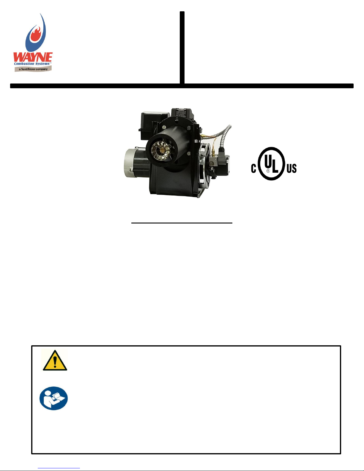
MODEL
EH, EHA &
EHASR
OIL BURNERS
Fuels: Use No.1 or No.2 heating oil (ASTM D-396),
Kerosene, Diesel (ASTM D975-18), JP8
Dimensions (Standard):
Height ……………………….…..…..12 1/2”
Width ……………………….…..……15 1/2”
Depth ………………………….…….. 8 1/4”
Center Line of Tube to Floor ......... 8 1/16”
Mounting:
Rigid Flange, Adjustable Flange, or Pedestal
Mount
READ THIS MANUAL BEFORE USING THIS PRODUCT. FAILURE TO FOLLOW THE
INSTRUCTIONS AND SAFETY PRECAUTIONS IN THIS MANUAL CAN RESULT IN
SERIOUS INJURY OR DEATH. KEEP THIS MANUAL FOR FUTURE REFERENCE.
INSTALLER: LEAVE THIS MANUAL WITH THE END USER.
INSTALLATION OF THE BURNER MUST BE DONE BY A QUALIFIED INSTALLER IN
ACCORDANCE WITH REGULATIONS OF THE NATIONAL FIRE PROTECTION
AGENCY, NFPA NO. 31, AND IN COMPLETE ACCORDANCE WITH ALL LOCAL
CODES AND AUTHORITIES HAVING JURISDICTION.
A QUALIFIED INSTALLER IS THE PERSON WHO IS RESPONSIBLE FOR THE
INSTALLATION AND ADJUSTMENT OF THE EQUIPMENT AND WHO IS LICENSED TO
INSTALL OIL-BURNING EQUIPMENT IN ACCORDANCE WITH ALL CODES AND
ORDINANCES.
Manual 21530 | Revision 10 | Publication Date: 9/14/18
1
Page 2
INSTALLATION LOG
BURNER MODEL:
SPECIFICATION NUMBER:
FUEL:
Nozzle Size and Pattern:
Pump Fuel Pressure (psi):
CO2 (%):
Smoke Spot:
CO (PPM):
INSTALLER’S NAME:
CONTRACTOR NAME:
CONTRACTOR
ADDRESS:
CONTRACTOR PHONE
NUMBER:
CONTRACTOR LICENSE #:
DATE OF INSTALLATION:
COMMENTS ABOUT INSTALLATION/START UP:
BURNER/APPLIANCE SERVICE LOG
SERVICE
DATE
TECHNICIAN
COMPANY
/ ADDRESS
CONTRACTOR
LICENSE #
WORK PERFORMED
/ /
/ /
/ /
/ /
/ /
/ /
/ /
/ /
/ /
/ /
/ /
/ /
/ /
/ /
/ /
/ /
/ /
THESE INSTRUCTIONS SHOULD BE AFFIXED TO THE BURNER OR ADJACENT TO THE
HEATING APPLIANCE.
2
Page 3
Overview of Safety Warning System and Your Responsibilities
Indicates a hazardous situation, which, if not avoided, will result in
death or serious bodily injury.
Indicates a hazardous situation, which, if not avoided, could result in
death or serious bodily injury.
Indicates a hazardous situation, which, if not avoided may result in
minor or moderate bodily injury.
Indicates a situation that may result in equipment-related damage.
This is the safety alert symbol. It is used to alert you to potential personal injury
hazards. The meaning of this safety alert symbol is as follows: Attention! Become
alert! Your safety may be at risk. The message that appears next to the warning
describes the hazard, which can be either written or pictorially presented. NEVER
remove or tamper with the warning labels, safety devices or guards fitted on the unit.
Wayne Combustion Systems is NOT responsible for any bodily injury and/or property
damage that may result from operation outside of the stated operating conditions for
which this unit was intended.
The safety of you and others depends upon you thoroughly reading and understanding this manual. If you have questions
or do not understand the information presented in this manual, please call Wayne Combustion Systems or see
www.waynecombustion.com.
Hazard Definitions:
3
Page 4
Hazard Level
Pictogram
Type
Hazard Explanation
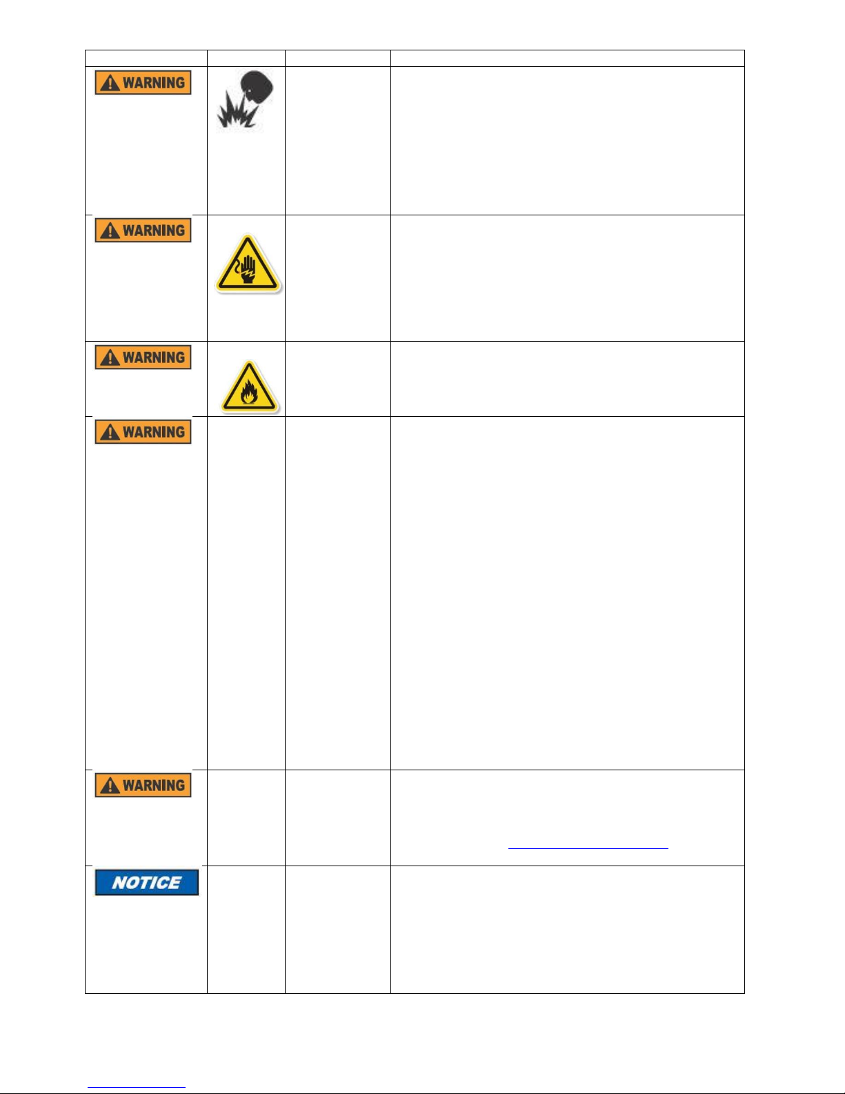
Fire or
Explosion
Failure to follow safety warnings exactly could result in
serious injury, death or property damage.
Do not store or use gasoline or other flammable vapors
and liquids in the vicinity of this or any other appliance.
Never attempt to use gasoline as a fuel for this burner,
as it is more combustible and could result in a serious
explosion.
Electric Shock
or Burn
High voltages are present in this equipment. Follow
these rules to avoid electric shock:
Use only a properly grounded circuit. A ground
fault interrupter is recommended.
Do not spray water directly on burner.
Turn off power before servicing.
Read the owner’s manual before using.
Overheating
Should overheating occur:
Shut off the manual oil valve to the appliance.
Do not shut off the control switch to the pump
or blower.
Carbon
Monoxide
Poisoning
Carbon monoxide is a colorless, odorless gas that
can kill. Follow these rules to control carbon
monoxide:
Do not use this burner if in an unvented,
enclosed area. Carbon monoxide may
accumulate.
Check flue gases for carbon monoxide. This
check requires specialized equipment.
Allow only qualified burner service persons to
adjust the burner. Special instruments and
training are required.
Read the burner manual before using.
CARBON MONOXIDE POISONING: Early signs of
carbon monoxide poisoning are similar to the flu with
headaches, dizziness, weakness, nausea, vomiting,
sleepiness, and confusion. If you suspect carbon
monoxide poisoning, get outside to fresh air
immediately, and then call 911. Some people are more
affected by carbon monoxide than others. These
include pregnant women, people with heart or lung
disease or anemia, those under the influence of
alcohol, and those at high altitudes.
Proposition 65
material
This product can expose you to chemicals, including
lead, nickel, carbon monoxide and sulfur dioxide, which
are known to the State of California to cause cancer or
birth defects or other reproductive harm. For more
information, go to www.p65Warnings.ca.gov.
Special
Requirements
When contacting Wayne Combustion Systems for
service information, please have the burner
specification and model number when calling or writing.
Specification number will be located on a 1” X 2”
rectangular sticker on the back of the burner and model
number is on the big square sticker that has the
manufacturer’s logo and contact information. This
sticker will be above the specification label.
4
Page 5

Contents
GENERAL INFORMATION ............................................................................................................................... 6
TROUBLESHOOTING....................................................................................................................................... 7
GENERAL TROUBLESHOOTING GUIDE ..................................................................................................... 7
BURNER DOES NOT LIGHT, HONEYWELL CONTROL REMAINS ON STANDBY .................................... 10
BURNER WILL LIGHT, BUT WILL NOT STAY LIT DURING “CALL FOR HEAT” ........................................ 11
WIRING DIAGRAMS ....................................................................................................................................... 16
SEQUENCE OF OPERATION: BURNERS WITH R7284G AND R8184G CONTROLS .................................. 17
SEQUENCE OF OPERATION: BURNER WITH R7284P CONTROL .............................................................. 18
SEQUENCE OF OPERATION: BURNER WITHOUT CONTROL .................................................................... 19
OPERATIONAL CHECK OF BURNER ............................................................................................................ 19
START SYSTEM ......................................................................................................................................... 19
CHECK SAFETY FEATURES ...................................................................................................................... 19
GENERAL INSTALLATION INFORMATION ................................................................................................... 20
COMBUSTION CHAMBER .......................................................................................................................... 20
FUEL PUMPS .............................................................................................................................................. 20
FUEL LINES ................................................................................................................................................ 20
FUEL TANKS ............................................................................................................................................... 21
ELECTRICAL WIRING OF BURNER ........................................................................................................... 21
CHIMNEY INSTALLATION .......................................................................................................................... 21
DRAFT REGULATORS ............................................................................................................................... 21
AIR SUPPLY FOR COMBUSTION .............................................................................................................. 22
NOZZLE AND AIR CONE SELECTION ....................................................................................................... 22
NOZZLE INSTALLATION ............................................................................................................................ 22
SETTING GUN DEPTH ............................................................................................................................... 27
STARTING PROCEDURE ............................................................................................................................... 30
STARTING BURNER ................................................................................................................................ ... 30
FINAL ADJUSTMENTS ............................................................................................................................... 32
SETTING COMBUSTION EFFICIENCY ...................................................................................................... 32
FINAL CHECKS ........................................................................................................................................... 33
MAINTENANCE .............................................................................................................................................. 33
REFERENCE INFORMATION ......................................................................................................................... 34
REFERENCE FIGURES .............................................................................................................................. 36
OIL PIPE SIZING INFORMATION ............................................................................................................... 37
WARRANTY .................................................................................................................................................... 39
5
Page 6

GENERAL INFORMATION
Read this manual carefully and in it’s entirety prior to performing any maintenance or service on
the burner.
WARRANTY
Wayne Combustion Systems warrants its burner’s specifically to organizations that have purchased it for resale, including
your dealer. If you have a problem with your burner, or its installation, you should contact your dealer for assistance, for a
full description of the warranty see page 39.
MAINTENANCE
Wayne Combustion Systems recommends yearly inspection/service of your oil heating system by a qualified service
agency or individual.
A qualified service agency or individual must be:
Licensed or certified to install and provide technical service to oil heating systems.
Experienced with all applicable codes, standards and ordinances.
Responsible for the correct installation and commission of the equipment.
Skilled in the adjustment of oil burners using combustion test instruments
APPROVALS
This burner complies with ANSI/UL Standard 296 and is for use with No. 1 fuel oil or No. 2 fuel oil and is UL listed for use
with Group I or Group II primary safety controls. The states of Massuchusetts, New York and local approvals are shown
on the burner’s nameplate label. All burners must be installed in accordance with the National Fire Protection Association,
and in complete accordance with all local codes and authorities having jurisdiction. Regulation of these authorities takes
precedence over the general instructions provided in this manual.
MANUAL ORGANIZATION
This manual is organized so that the licensed contractor can troubleshoot the service issue with the burner by working
through the GENERAL TROUBLESHOOTING GUIDE on page 7. The GENERAL TROUBLESHOOTING GUIDE is
organized by the performance issue or “problem” requiring attention. Each problem will list potential root causes that may
result in the problem listed in order from most likely to least likely, and the solution to correct each root cause that may be
affecting burner performance. The solution listed for each root cause will reference supplemental information regarding
normal burner/component operation and service instructions depending on the problem and root-cause. If this is a new
installation see GENERAL INSTALLATION INFORMATION on page 20.
MODEL DIFFERENCES
The EHASR burner utilizes unique air cones and oil gun assemblies to optimize burner performance in its rated firing
range. The air cone is a single piece construction and is fixed to the air tube. The oil gun depth is set in reference to the
fixed air cone The EH and EHA have the flamelock attached to the nozzle adaptor on the oil gun, this allows the burner to
have a variable gun depth setting based on the firing rate needed. An EHA burner is different from a EH because the EHA
uses an oil pump that is rated up to 3 gal/hr, while the EH model will use a larger pump that is rated up to 7 gal/hr to attain
the higher firing rates.
BURNER COMPONENTS
The EHASR, EHA, and EH model burners are constructed with components of varying design. For example, the ignition
device may be an iron core transformer or a solid state igniter. Both devices perform the same function, and they use the
same troubleshooting methodology. There are also two distinct types of motors utilized by these burners. The “Permanent
Split Capacitor” or PSC motors (silver in color) utilize a thermal protection device that automatically resets when the motor
cools down. The “Split-Phase” motors (black jacket) utilize a manual reset thermal protector. Appliance or equipment
manufacturers may specify one type of component over another. Please contact Wayne Combustion Systems for
assistance with replacement component selection.
6
Page 7
TROUBLESHOOTING
PROBLEM
POSSIBLE CAUSE
SOLUTION
BURNER WILL NOT
LIGHT
Little or no fuel
Fill tank with fuel.
Improper fuel or water in fuel
Drain fuel tank and fill with proper fuel.
Limit switch open
Close limit or thermostat switch, and check limit switch for
proper cycling operation.
Improper electrode spacing, gap to
small
Clean and position electrode tips according to Figure 14 or
Figure 15 on pages 26-27.
Plugged fuel filter
Replace as needed.
Misadjusted burner air bands
Re-adjust air bands for clean burn.
Little or no fuel pressure from fuel pump
Increase fuel pressure to manufacturer's specifications. See
Figure 25 on page 36 for pump features. Check that plastic
coupler (see Figure 1 on page 13, item 10) is not slipping on
pump shaft, replace as needed and/or replace pump.
Before troubleshooting, familiarize yourself with the startup procedures and
sequence of operation. Check the burner, ignitor or transformer, oil primary
control (if equipped), and cad cell (if equipped) for proper operation and condition.
The Honeywell R7284 oil primary control’s reset button is the “i” button, the R7184, R8184 and
Wayne control is the big red button. Pressing the reset button and restarting the burner more
than once with the burner not lighting could cause oil buildup in the firing chamber. This will
cause smoking and possible detonation that could damage the equipment if the burner does light
Preliminary Steps
Check the following common causes of issues:
Wiring connections, fuses, power supply to the burner blower motor, controls, and ignition device.
Limit control is closed.
Thermostat (controller) is calling for heat.
Contacts between ignition device and electrodes.
Electrode gap is properly set at nozzle.
Oil piping to burner and tank is properly sized and is in good condition (see Oil Pipe Sizing Information on
page 37 ).
Oil pump pressure.
Oil nozzle is correctly sized for application.
Check cad cell location and photo eye cleanliness.
GENERAL TROUBLESHOOTING GUIDE
7
Page 8

PROBLEM
POSSIBLE CAUSE
SOLUTION
BURNER WILL NOT
LIGHT
(continued)
Air bubble sucked and trapped in pump
Bleed pump (see page 31 for instructions) and check all fuel
lines for air leaks, replace lines as needed. See Figure 25 on
page 36 for pump features.
Burner motor thermal protector actuated
If tripped, check voltage, connections, and extensions for
cause. Check fuel pump shaft rotation for binding causing
motor to overheat.
Flex-coupling slipping on fuel pump
shaft or burner motor shaft
Replace as needed. See Figure 1 on page 13, Item 10.
Fuel not reaching combustion chamber
Check fuel system for proper flow going through the burner.
Clogged burner nozzle
Replace. See page 22 for instructions.
Low voltage at burner wire leads
Check for proper 120/230 Vac going to the burner
Fuel solenoid malfunction
Replace as needed. See Figure 1 on page 13 for
replacement part.
Faulty burner ignition device
Test ignition device for proper arc between contacts. Replace
as needed. See Figure 1 on page 13 for replacement part.
Disconnected or short in electrical wiring
All wire contacts should be clean and tight. No breaks in wire
insulation, replace as needed. See page 21 for wire size
recommendations.
Oil primary control sees light during
safety check and remains in standby
mode (Applicable only if burner comes
with oil primary control).
Press and hold the reset button for 2 seconds on a Honeywell
control, (push and hold for 3 seconds if it is an older style
Wayne control), observe burner sequence of operations. If
burner remains on standby see Burner does not light,
Honeywell controls remains on standby, on page 10.
Oil gun depth spaced too far ahead
causing electrodes too short to ground
through air cone.
Identify burner model and position oil gun depth according to
Figure 16 and Figure 17. See page 27 for instructions.
Heavy sooting on burner electrodes,
and air cone causing a weak arc
between the electrodes.
Clean as required. Check ceramic for any chips and cracks
that could affect arc between the electrodes, replace as
required. See Table 2 on page 15 for replacement parts.
BURNER WILL LIGHT,
BUT NOT STAY LIT
DURING CALL FOR HEAT
Oil primary control goes into nuisance
lockout (Applicable only if burner comes
with oil primary control).
Press and hold the reset button for 2 seconds on a Honeywell
control, (push and hold for 3 seconds if it is an older style
Wayne control), observe burner sequence of operations. If
burner locks out again see Burner Will Light, But Will Not
Stay Lit During “Call For Heat”, on page 11.
BURNER SMOKES
Improper fuel or water in fuel
Drain tank and replace contaminated fuel.
Improper air adjustment
Re-adjust air bands on burner assembly for clean burn.
Low fuel pressure
Increase fuel pressure to manufacturer's specifications. See
Figure 25 on page 36 for pump features.
Air leaks in fuel lines
Check fuel lines for leaks or air bubbles. Tighten or replace
as needed.
Plugged or dirty burner nozzle
Replace burner nozzle. See page 22 for instructions.
Improper nozzle size installed, nozzle
size too big
Contact appliance manufacturer for proper nozzle size, and
replace. See page 22 for instructions.
8
Page 9

PROBLEM
POSSIBLE CAUSE
SOLUTION
BURNER SMOKES
(continued)
Heavy accumulation of soot on heat
exchanger and burner assembly
Remove burner assembly from heat exchanger. Clean
thoroughly.
Faulty burner nozzle spray pattern
Replace. See page 22 for instructions.
Misaligned or damaged electrode
Realign electrodes according to Figure 14 or Figure 15 on
pages 26-27, and the oil gun depth according to Figure 16 or
Figure 17 on pages 27-28.
Obstruction in smoke stack
Check for blockage or other foreign objects.
BURNER RUNS
CONTINOUSLY WITHOUT
SATISFYING CALL FOR
HEAT
Improper fuel or water in fuel
Drain fuel tank and fill with proper fuel.
Reduced fuel pressure
Check fuel pump pressure. Check that fuel filter isn’t partially
clogged, replace as necessary. Increase fuel pressure to
manufacturer's specifications. See Figure 25 on page 36 for
pump features. Replace pump if needed.
Soot build-up on heat exchanger.
Clean heat exchanger with soot remover.
Improper burner nozzle installed, nozzle
size too small.
Contact appliance manufacturer for proper nozzle size, and
replace. See page 22 for instructions.
BURNER RUNS BUT
APPLIANCE IS
OVERHEATING
Fuel pump pressure too high
Readjust fuel pressure to appliance manufacturer's specs.
See Figure 25 on page 36 for pump features.
Oil primary control keeps energizing
burner past “call for heat”. (Applicable
only if burner comes with oil primary
control).
Identify control model. Replace Control, and wire accordingly
to Figure 3 or Figure 4 on page 16.
Faulty fuel pump shut-off valve
Replace fuel pump shut-off valve.
Defective high limit switch or
Thermostat
Replace.
Incorrect fuel nozzle size, nozzle size
too big
Contact appliance manufacturer for proper nozzle size, and
replace. See page 22 for instructions.
BURNER MOTOR WILL
NOT RUN
Overload protector activated
Wait 20 minutes for motor to cool down, will restart
automatically.
Faulty oil primary control. (Applicable
only if burner comes with oil primary
control).
Observe burner sequence of operations. Check voltage going
to the burner motor if it does not run during the 15 second
trial for ignition, replace control.
Fuel pump seized
Replace fuel pump. See Figure 1 on page 13 for replacement
parts
Burner fan loose or misaligned
Identify fan part number by measuring O.D of fan then
reference Table 1 on page 14 and position the fan spacing
according to Figure 26 on page 36 and tighten set screw.
Defective control switch
Replace switch.
Loose wire
Check and replace or tighten wiring.
Defective burner motor
Replace motor.
BURNER STAYS ON
WHEN NO CALL FOR
HEAT
Faulty oil primary control. (Applicable
only if burner comes with ignition
control).
Observe burner sequence of operations. Replace control if
necessary
Thermostat defective
Check for proper operation, replace if necessary.
Fuel solenoid defective
Replace fuel solenoid.
9
Page 10

Procedure
Status
Corrective Actions
1. Make sure limit
switches are closed
---------------------
---------------------
2. Check for line voltage
power at primary
Control. 120 vac.
---------------------
Check breaker and investigate appliance wiring
3. Check R7284G or
R8184G indicator light,
(LED Screen if R7284P
control) with burner off,
no call for heat. No
Flame.
R7284G & R8184G indicator
light is pulsing (1/4 sec. ON, 4
sec. OFF), R7284P display
would say “STANDBY”
Sees external light during safety check or
connections are shorted,
4. Shield cad cell from
external light
R7284G & R8184G indicator
light starts pulsing (1/4 sec. ON,
4 sec. OFF), R7284P display
will read “STANDBY”
Energize thermostat to verify that burner goes
through proper sequence of operations.
If burner does not light go to step 5
5. Jumper oil primary T-T
terminals
Burner starts
Trouble in thermostat or limit circuit. Check wiring
connections
Burner does not start
Disconnect line voltage and open thermostat or
limit switch.
If burner does not start, replace primary control.
NOTE: This section refers to Honeywell R7284 and R8184 series controls. The R7284G and
R8184G control use a LED light to display the troubleshooting status, and the R7284P
control comes with a display screen that will output the current operating state of the
burner or any troubleshooting errors that might arise in normal burner operation.
Troubleshooting tables on pages 10-11 are specific to burners that
come equipped with an oil primary control, and these sections only
apply if the general troubleshooting guide tells the licensed
contractor to consult these sections while servicing the burner.
BURNER DOES NOT LIGHT, HONEYWELL CONTROL REMAINS ON STANDBY
10
Page 11

BURNER WILL LIGHT, BUT WILL NOT STAY LIT DURING “CALL FOR HEAT”
Procedure
Status
Corrective Actions
1. Check limit switches
---------------------
---------------------
2. Check for line voltage at
the oil primary control
(120 volts)
---------------------
---------------------
3. Check R7284G or
R8184G indicator light,
(LED Screen if R7284P
control) with burner on,
call for heat.
R7284 or R8184 control is in
lockout. The R7284G &
R8184G control LED flashes for
½ seconds ON, ½ seconds
OFF. The R7284P control reads
“Lockout Mode”
Control is sensing bad flame signal, cad cell or
controller is defective, sees external light or
connections are shorted. Go to step 5.
The R7284P display reads
“Valve on Delay”
Go to step 4.
4. Applications with “valve
on delay”, verify that oil
valve is closed during
the “valve on delay”
period by opening view
port and verifying that
no flame is present
during 15 second “valve
on delay”
R7284P display still reads
“Valve on Delay”
If flame is present, replace valve.
5. Jumper oil primary T-T
terminals
Burner starts, and stays
running.
Trouble is in thermostat or limit circuit.
Burner starts, but doesn’t stay
running.
Disconnect line voltage and open thermostat or
limit switch.
Check all wiring connections
If burner does not stay running, go to step 6
6. Check that nozzle size
is per appliance
manufacturer
recommendation
Burner nozzle incorrect.
Change nozzle and fuel pressure to factory settings
and retest, if burner doesn’t stay lit go to step 7
Burner nozzle correct
Go to step 7
7. Check burner air band
setting is set up per
manufacturer
recommendation
Burner air band setting too low.
Could cause black puff of smoke on ignition if the
fuel-air mixture is too rich.
Use a combustion test kit to measure the CO2 %
and smoke spot in the exhaust.
Adjust air band opening until CO2 % measures
between 10-12 %, and smoke spot is a 1 or less.
If problem persists go to step 8
Burner air band setting too high
Could cause delayed ignition on start-up if the fuel-
air mixture is too lean.
Use a combustion test kit to measure the CO2 %
and smoke spot in the exhaust.
Adjust air band opening until CO2 % measures
between 10-12 %, and smoke spot is a 1 or less.
If problem persists go to step 8
Burner air band set at
manufacturers
recommendations
Go to step 8
11
Page 12

8. Check cad cell sighting
for view of flame.
- Disconnect line
voltage power and
open line switch.
- Unplug cad cell and
clean face with soft
cloth. Check
sighting for view of
flame. Place cad
cell back in socket.
- Reconnect line
voltage and close
line switch.
- Start burner,
Burner locks out.
Go to step 9
Burner keeps running, until “call
for heat” is satisfied.
System is okay.
9. Check Control & Cad
cell.
- Remove cad cell
wires from
connectors on
primary and leave
lead wires open.
- Apply power to
device
- Place jumper
across cad cell
terminals after
burner motor turns
on.
Burner doesn’t run.
Replace primary control.
Burner runs.
Control is okay, replace cad cell.
12
Page 13

Figure 1- Burner Components – Models EHASR, EHA, and EH
13
Page 14

Table 1- EHASR, EHA, and EH Replacement Parts
No.
Description
EHA
EH
EHASR
No.
Description
EHA
EH
EHASR
1
Motor - 1/5 HP,
120V PSC
24003-001
24003-001
12B
2)
Pump – A2VA3006/120V SOL.
101128-009
Motor – 1/5 HP,
120V Cap Start
21569
21569
12B 2)
120V Solenoid
Valve- A2VA3006 pump
100885-001
Motor - 1/4HP,
120V PSC
24005-001
24005-001
24005-001
12B 2)
Pump- A2VA3006/230V SOL.
101128-010
Motor – 1/4 HP,
120V Cap Start
21126
21126
12B 2)
230V Solenoid
Valve- A2VA3006 pump
100885-002
Motor - 1/5 HP,
230V PSC
24006-001
24006-001
13
Cad Cell - Up to
12" Tube
14289-KIT
14289-KIT
14289-KIT
Motor - 1/4HP,
230V PSC
24004-001
24004-001
24004-001
Cad Cell - 12" +
Tubes
13666-KIT
13666-KIT
13666-KIT
2
Motor Cord Cover
13121
13121
13121
14A 3)
Brass Connector
14222
14222
14222
3
Fan - 5 1/4" Outer
Diameter
20288
20288
20288
14B
3), 4)
Brass Connector
90° Elbow
13494
13494
13494
Fan - 5 3/4" Outer
Diameter
20887
20887
20887
15 3)
120V Solenoid
Valve
100610-001
100610-001
100610-001
Fan - 6 1/4" Outer
Diameter
21854
21854
21854
230V Solenoid
Valve
100610-002
100610-002
100610-002
4
Burner Housing Painted
20372
20372
20372
16
Gun Assembly
(See NOTE Below)
5
120V Ignitor-Iron
Core
23101-E
23101-E
23101-E
17
Air Tube
(See NOTE Below)
230V Ignitor-Iron
Core
23103-E
23103-E
23103-E
18A
1)
Cast Iron - 2 3/4"
No Vane
13002
120V Ignitor-Solid
State
101295-SERE
101295-SERE
101295-SERE
18A
1)
Cast Iron - 3" No
Vane
12989
12989
230V Ignitor-Solid
State
101391-SERE
101391-SERE
101391-SERE
18A
1)
Cast Iron - 3 1/4"
No Vane
12990
12990
6
120V Control - 15
second, Honeywell
R7284G
101343-SER
101343-SER
101343-SER
18A
1)
Cast Iron - 3
9/16" No Vane
13003
230V Control - 15
second, Honeywell
R8184G
100490-001
18B
1)
Stainless - SR
#1A
14157
120V Control - 15
second, Honeywell
R7284P
101278-SER
101278-SER
101278-SER
18B
1)
Stainless - SR
#2A
14158
7
Slot Cover Plate
13392
13392
13392
18B
1)
Stainless - SR
#3A
14159
8
Air Band - Inner 8
Slot
2669-002
2669-002
2669-002
18B
1)
Stainless - SR
#4A
14160
9
Air Band - Outer 8
Slot
2668-002
2668-002
2668-002
19
Flange
21426
21426
21426
Air Band - Outer 5
Slot
20310-002
20310-002
20
Gasket
12484
12484
12484
10 4)
Coupling - A/B
Pump
13279
13279
13279
21
Adjustable
Flange
2689-SER
2689-SER
2689-SER
Coupling w/ set
screws – A/B Pump
100838-001
22
Junction Box
21319
21319
21319
11
4)
Oil Line Assembly
14452
14452
14452
Not
Shown
Pedestal
2794-011
2794-011
2794-011
12A 3)
Pump - A2VA-7116
13495
13495
Not
Shown
Tune-Up Kit
31156
31156
31156
12A 3)
Pump - A2YA-7916
14375-SER
NOTE: STATE SPECIFICATION NUMBER, BURNER MODEL, PART DESCRIPTION AND PART NUMBER WHEN ORDERING PARTS
1) Cast Iron Cones - Measure machined ID. Stainless Steel Air Cones - Number/Letter combination stamped into face of outer ring.
2) Item 12B are oil pumps that come with oil solenoid valves already attached, but replacement parts are available for replacing the fuel solenoid.
3) Item 12A are oil pumps that do not come with solenoid valves, solenoid valves are optional for these model. If oil pump comes with a solenoid
valve (item 15), item number 14A must be used. If oil pump does not come with a solenoid valve, brass connector elbow 14B must be used.
4) Part included in 31156 Tune-Up Kit
= Item not available for purchase on that specific burner model
14
Page 15

No.
Part Description
EHA
EH
EHASR
1
Nozzle Adaptor
12988-002
12988-002
21913-SER
2
Stamped Stabilizer Support Kit
21923-001
21923-001
21923-001
Cast Stabilizer Support Kit
21408-SER
21408-SER
21408-SER
3
Stem/Insulator Kit
13286
13286
13286
4
Cad Cell Mount
13078
13078
13078 5 Buss Bar Support
13276-002
13276-002
13276-002 6 Cad Cell Wire Tie
100850-001
100850-001
100850-001 7 Oil Pipe Fitting
14295-002
14295-002
14295-002
Figure 2– Oil Gun Assembly Detail View
(Parts not necessarily as shown)
Table 2- Oil Gun Replacement Parts
15
Page 16

WIRING DIAGRAMS
REMOVE JUMPER
TO USE
THERMOSTAT
TERMINALS
REMOVE JUMPER
TO USE
THERMOSTAT
TERMINALS
Figure 3- Wiring Diagram for 120V Honeywell R7284G & 230V Honeywell R8184G Controls
Figure 4- Wiring Diagram for 120V Honeywell R7284P Control
16
Page 17

Do not keep pressing the reset button and restarting the burner more than once with the burner not
lighting this could cause oil buildup in the firing chamber. This will cause smoking and possible detonation that could
damage the equipment if the burner does light.
Figure 5- Wiring Diagram for 120/230V Burners without a control
SEQUENCE OF OPERATION: BURNERS WITH R7284G AND R8184G CONTROLS
BURNER OPERATION
On every call for heat the oil primary control performs an internal safety check which takes five seconds to complete.
During these five seconds, the oil primary control verifies that the cad cell is outputting a “no flame” resistance value. After
the check, the oil primary control will simultaneously energize the burner blower motor, solenoid valve (if equipped), and
ignition device. The control will then enter the 15 second trial for ignition period; once flame is established the oil primary
control will continue to monitor the flame by using the cad cell’s resistance value. The oil primary control allows burner
operation to continue until the thermostat control’s “call for heat” is satisfied. Once the thermostat is satisfied the burner
will be de-energized. If flame is not detected during the trial for ignition, the oil primary control will go into a “lock-out”
condition. If this occurs, proceed to the section titled SAFETY LOCK-OUT TIME.
SAFETY LOCK-OUT TIME
Ignition failure occurs during the first “trial for ignition” period
The cad cell monitors the combustion chamber for flame during the burner’s trial for ignition period. If no flame is detected
the oil primary control will go into a lockout condition. When the oil primary control goes into lockout it will de-energize the
burner, and the control’s LED light will flash ½ sec on, and ½ sec off. Before attempting to start the burner again the
control must be reset. Press and hold the “i” button for three seconds to reset the control. If normal ignition does not occur
see GENERAL TROUBLESHOOTING GUIDE on page 7.
17
Page 18

Intermittent flame failure occurs during a “call for heat”
Do not keep pressing the reset button and restarting the burner more than once with the burner not
lighting this could cause oil buildup in the firing chamber. This will cause smoking and possible detonation that could
damage the equipment if the burner does light.
If the oil primary control stops sensing a flame after the flame has been proven and the trial for ignition timer has expired,
the oil primary control enters a limited recycle mode where it will de-energize the burner for one minute, while the LED
light will flash for 2 seconds on, and 2 seconds off. After one minute the oil primary control resumes the call for heat, and
enters another “trial for ignition” period. If a flame is proven during the trial for ignition, and lost after the trial for ignition
timer expires the control will go into another recycle mode countdown. If no flame is proven during the trial for ignition
period the control will go into a lockout condition. If the control tries three recycle modes where flame is proven, and then
subsequently lost the control will go into a hard lockout condition de-energizing the burner. If normal ignition does not
occur see GENERAL TROUBLESHOOTING GUIDE on page 7.
SEQUENCE OF OPERATION: BURNER WITH R7284P CONTROL
BURNER OPERATION
On every call for heat the oil primary control performs an internal safety check which takes five seconds to complete.
During these five seconds, the oil primary control verifies that the cad cell is outputting a “no flame” resistance value. After
the check, the oil primary control will simultaneously energize the burner blower motor, solenoid valve (if equipped), and
ignition device. The oil primary control will then enter the 15 second trial for ignition period; once flame is established the
oil primary control will continue to monitor the flame by using the cad cell, and it will de-energize the ignitor after 10
seconds. The oil primary control allows burner operation to continue until the thermostat control’s “call for heat” is
satisfied. Once the thermostat is satisfied the burner will be de-energized. If flame is not detected during the trial for
ignition, the oil primary control will go into a “lock-out” condition. If this occurs, proceed to the section titled SAFETY
LOCK-OUT TIME.
SAFETY LOCK-OUT TIME
Ignition failure occurs during the first “trial for ignition” period
The cad cell monitors the combustion chamber for flame during the burner’s trial for ignition period. If no flame is detected
the oil primary control will go into a lockout condition. When the control goes into lockout it will de-energize the burner,
and the control’s screen will display “lockout mode”. Before attempting to start the burner again the control must be reset.
Press and hold the “i” button for three seconds to reset the control. If normal ignition does not occur see GENERAL
TROUBLESHOOTING GUIDE on page 7.
Intermittent flame failure occurs during a “call for heat”
If the oil primary control stops sensing a flame after the flame has been proven and the trial for ignition timer has expired,
the oil primary control enters a limited recycle mode where it will de-energize the burner for one minute while displaying
“recycle” on the display screen. After one minute the oil primary control resumes the call for heat, and enters another “trial
for ignition” period. If a flame is proven during the trial for ignition, and lost after the trial for ignition timer expires the oil
primary control will go into another recycle mode countdown. If no flame is proven during the trial for ignition period the oil
primary control will go into a lockout condition. If the oil primary control tries three recycle modes where flame is proven,
and then subsequently lost the control will go into a hard lockout condition de-energizing the burner. If normal ignition
does not occur see GENERAL TROUBLESHOOTING GUIDE on page 7.
18
Page 19

SEQUENCE OF OPERATION: BURNER WITHOUT CONTROL
Make sure combustion chamber is free of oil or oil vapor before starting system.
BURNER OPERATION
If the burner is controlled by a high voltage limit switch on the incoming power line to the burner, the operation of the
burner is a simple ON/OFF mechanism, where all the burner components will be energized simultaneously to fire the
burner. If any problems arise during ignition or continued operation of the burner see the GENERAL
TROUBLESHOOTING GUIDE on page 7.
OPERATIONAL CHECK OF BURNER
START SYSTEM
Open hand valve in oil supply line.
Make sure system is electrically energized, check circuit breaker, fuses, and close system switch if
provided.
Press and hold the oil primary control i button for two seconds and release (big red button for three
seconds for old Wayne control).
Set thermostat (controller) to “call for heat”.
Burner should light and operate until call for heat is satisfied.
Simulate flame failure
Follow starting procedures to turn on burner.
Close hand valve on supply line, stopping fuel delivery to the burner.
The oil primary control should lockout after control’s trial for ignition timer expires. The burner
blower motor and ignition device should stop, and the solenoid valve should close.
Simulate ignition failure
Close hand valve on supply line, stopping fuel delivery to the burner.
Follow starting procedures to turn on burner.
Oil primary control should lockout after control’s trial for ignition timer expires. The burner blower
motor and igniter should stop, and the solenoid valve should close.
Simulate power failure
With burner running, turn off power supply to the system.
Burner should stop.
Restore power, burner should start.
If system does not operate as described, proceed to GENERAL TROUBLESHOOTING GUIDE on
page 7
CHECK SAFETY FEATURES
19
Page 20

GENERAL INSTALLATION INFORMATION
Never exceed 3 PSI pressure to the suction side of the fuel pump. A pressure over 3 PSI
may cause damage to the shaft seal and allow it to leak oil.
Do not install by-pass plug if running single pipe operation, this will over-pressurize the pump
causing an oil leak at the pump shaft seal.
When installing the burner, be sure to provide adequate space for easy service and maintenance. Prior to installation of
the oil burner, the heating system should be carefully inspected for defects and cleanliness. The flue passages and heat
absorbing surfaces must be clean to ensure maximum heat transfer. Soot acts as an insulator, which retards the transfer
of heat. The combustion chamber, flue gas passages, and all doors and openings must be tightly sealed to eliminate air
infiltration. Excess air cools the flame and thus lowers efficiency. Inspect the flue and chimney for leaks and obstructions.
Be sure the chimney is of adequate size and height. Install a draft regulator the same size as the flue pipe (see paragraph
under DRAFT REGULATORS).
COMBUSTION CHAMBER
The purpose of a combustion chamber is to maintain a high flame temperature by reflecting the heat back into the flame.
A high flame temperature assures greater combustion efficiency and lower stack losses. An insulating refractory or a Fiber
Fax type chamber can be used with this burner. It is important to select and install, the correct nozzle size for a given
combustion chamber size (see Table 4 on page 35). On all oil burners the atomized oil must not touch the sides or bottom
of the combustion chamber or improper combustion will occur leading to smoke and soot build-up. To reduce smoke while
the burner is running, the burner must have an adequate supply of combustion air by having a large enough opening on
the air band assembly. If too much air is utilized it can lead to high gas exhaust temperatures, and lower combustion
efficiency. Install the burner so the face of the air cone on the burner is set a ¼ inch behind the inside front wall of the
chamber (see Figure 20 on page 30).
FUEL PUMPS
Model EHASR, EHA and EH oil burners are provided with single stage 3450 RPM fuel pumps with the by-pass plug
removed for a single pipe installation. This is satisfactory where the fuel supply is on the same level, or above burner,
permitting gravity flow of oil.
When it is necessary to lift the oil to the burner, a return line should be run between the fuel pump and oil tank. (If lift
exceeds 10 feet, a two stage fuel pump must be used with a return line). When a two line installation is made, the by-pass
plug must be installed. This is supplied with the burner attached to fuel pump, along with a pump data sheet in a plastic
bag.
FUEL LINES
When oil lines are continuous runs, heavy wall copper tubing is recommended for the fuel lines. Be sure that all
connections are absolutely air-tight. Check all connections and joints. Flared fittings are recommended. Do not use
compression fittings. Avoid running tubing against the appliance and across ceiling or floor joist; if possible install under
floor. Avoid using fittings in inaccessible locations. If possible, avoid running oil lines overhead. Specific information on
piping, connections, lift capabilities and tank installations is provided in the instruction sheet of the fuel pump
manufacturer, however if the instruction gets damaged or unreadable see oil pipe sizing information under reference
information on page 37. Install an UL certified oil filter of adequate size for all installations.
20
Page 21

FUEL TANKS
Label all wires prior to disconnection when servicing burners. Wiring errors can cause
improper and dangerous operation. Verify proper operation after servicing
If any of the original burner wiring must be replaced, it must be replaced with
#18 AWG 105°C wire or equivalent
Local codes and regulations must be followed regarding tank and burner installation. Check existing tanks for water and
sludge accumulation; clean if necessary. Also clean or replace existing piping.
ELECTRICAL WIRING OF BURNER
The oil burner is shipped completely wired. It is only necessary to supply the line voltage circuit, thermostat and limit
circuit. All wiring must comply with the National Electric Code or the code legally authorized in the locality where the
installation is being made. The burner, when installed must be electrically grounded in accordance with local codes or, in
absence of local codes, with the latest edition of the National Electrical Code, ANSI/NFPA No. 70. Refer to wiring
diagrams Figure 3,Figure 4 and Figure 5 on pages 16 & 17 for reference on wiring, and thermostat connection. If an
external electrical source is utilized, the oil burner, when installed, must be electrically grounded in accordance with local
codes or, in the absence of local codes, with the latest edition of the National Electrical Code, ANSI/NFPA No. 70.
For line voltage wiring to the burner use solid copper conductor wire not lighter than #14 AWG. If a fused disconnect is
used, it should be fused for a minimum of 20 amps.
If the oil burner comes equipped with an oil primary control, the burner will be shipped with a jumper wire on the
thermostat (T-T) terminals. The jumper needs to be removed for remote thermostat control and the thermostat needs to
be connected per wiring diagrams. A T-T terminal is an open/close switch for the oil primary control and no voltage should
be connected to it. For boilers it may be necessary to leave the T-T terminal jumped as the aquastat may be providing the
voltage to the burner and controlling when voltage is sent to the burner. The burner is controlled by the appliance. Once
wiring is complete between burner and appliance, verify that the appliance is controlling the burner’s on/off operation.
When connecting the burner to the line voltage electrical supply, utilize the knockout provided on the burner’s junction
box.
CHIMNEY INSTALLATION
Follow the recommendations of the appliance manufacturer. A chimney shall be capable of producing a draft as
recommended by the appliance manufacturer. It must be properly designed, of adequate size, be above the surrounding
objects, tile-lined, with no obstructions, and be in a good state of repair. The smoke pipe should sit flush with the inside of
the tile and be cemented in place. All cleanout doors should be sealed. A draft inducer may be used to overcome
inadequate draft conditions. If a draft inducer is used, provisions must be made to ensure the burner does not operate if
the draft inducer fails.
DRAFT REGULATORS
A draft regulator shall be provided unless otherwise specified by the appliance manufacturer. The draft regulator shall be
installed in accordance with local codes and regulations or in the absence of local codes, with ANSI NFPA31. Refer to
appliance manufacturer’s instructions for recommended over fire and stack draft.
21
Page 22

AIR SUPPLY FOR COMBUSTION
Arrow
Decal
Slot
cover
A burner shall not be installed in an area where normal air circulation or infiltration is limited and it restricts the amount of
air necessary for proper combustion and venting. When the heating appliance is installed in a confined space, two
permanent air openings shall be provided; one near the top of the enclosure and one near the bottom. Each opening shall
have a free area of no less than one square inch per 1000 Btu/hr (140 square inch per gal/hr) of the total input rating of all
the appliances in the space. When the house is of unusually tight construction, has a kitchen ventilating system, exhaust
fans, clothes dryer or vented fireplaces, it is recommended that combustion air be supplied through two permanent
openings. The openings should connect directly, or by means of ducts, with outdoors or to such spaces (attic or crawl)
that are exposed to the outdoors. For additional information, refer to ANSI standard NFPA31.
NOZZLE AND AIR CONE SELECTION
The EHASR, EHA, and EH oil burners typically fire well with a solid or semi-solid nozzle with a spray angle of 80, 70, or
60 degrees. In most upgrading or conversion installations, the use of an 80 degree solid nozzle is a good starting point.
Always use the proper nozzle size, spray cone type and spray angle the appliance manufacturer recommends. Should
this information not be available, your own good judgment will prevail. Under no circumstances attempt to fire the EHA or
EHASR oil burners under their 0.75 gal/hr minimum input rating or over their 3.00 gal/hr maximum input rating. Under no
circumstances attempt to fire the EH oil burner under its 3.00 gal/hr minimum input rating or over its 6.00 gal/hr maximum
input ratings.
NOZZLE INSTALLATION
In order to install or change the nozzle, the oil gun assembly needs to be removed from the burner. The EHASR, EHA,
and EH burners has an arrow decal that lines up with the leading edge of the oil gun slot cover plate. This will help with reinstalling the oil gun in the proper position once the nozzle has been installed. See Figure 6 for part identification.
plate
Figure 6– EH/ EHASR Side View of Oil Gun Slot Plate Cover
1. Locate the slot plate cover, loosen the brass oil assembly nut with a 7/16 inch wrench at the connection with the brass
fitting on the solenoid valve, but do not remove all the way. (Figure 7 on page 23).
Note-For pumps with combination solenoid valves disconnect the oil line from the brass elbow fitting installed in the
nozzle port of the pump.
22
Page 23

Figure 7 EH/EHASR Oil Line Assembly Fitting
2. Loosen and disconnect the brass nut of the copper oil line assembly from the oil gun assembly fitting and rotate the oil
line out of the way (Figure 8).
Figure 8 EH/EHASR Oil Line Removal
23
Page 24

3. Next loosen the ignition device mounting plate clip screw by using a flat head screwdriver, move the hold down clip off
Hold
down
clip
Motor
Flange
Hold
down
clip
of the mounting plate, this will allow the igniter device assembly to swing open to the left. For now leave the plate in
the closed position (Figure 9).
Figure 9 EH/EHASR Ignitor mounting plate screw removal
4. Using a 9/16 inch wrench loosen and remove the oil gun assembly locknut (Figure 10).
Figure 10 EH/EHASR Oil Gun Lock Nut Removal
24
Page 25

5. Now grasp the rear of the oil gun assembly where the oil line fitting adapter exits through the housing and pull the oil
gun to the right out of the housing slot and the slot plate cover (Figure 11).
Figure 11 EH/EHASR Oil Gun Removal
6. While rotating the oil line fitting adapter up at a 45 degree angle, gently lift, but do not force, the entire gun assembly
out of the housing opening (Figure 12).
Figure 12 EH/EHASR Oil Gun Removal (Continued)
25
Page 26

7. Thread the nozzle into the nozzle adaptor finger tight, then tighten the nozzle securely with a 5/8” wrench, while using
DO NOT touch the new nozzle’s filter or touch the face of the nozzle. Oil from
your fingers on either surface can adversely affect nozzle performance
Stamp
a 3/4" backing wrench to hold the nozzle adapter. Do not over tighten. There is a brass stamp that reads “TOP” on the
nozzle adapter that should be orientated up (Figure 13).
Figure 13 EH/EHASR Oil Gun Nozzle Installation (Flamelock and electrodes removed for
clarity).
8. Identify which burner model you have, then measure and verify that the electrode spacing is per Figure 14 or Figure
15 on page 27, if not correct to factory settings.
Figure 14–EH Electrode Positions, Factory settings
26
Page 27

FLAMELOCK
Figure 15–EHASR Electrode Positions, Factory settings
9. At this time position the gun assembly back into the housing in reverse sequence that gun assembly was removed in,
while taking care not to disrupt the electrode spacing.
Note: Re-measure electrodes gap after installing gun assembly in burner to verify that the position has not shifted
SETTING GUN DEPTH
For the oil burner to function properly the distance between the nozzle and the air cone needs to be maintained as shown
in Figure 16 & Figure 17 on page 28.
(For EHA and EH Burners Only)
Suggested startup setting: EHA Flamelock flush with cast iron cone face. EH Flamelock 1/8” ahead of cast iron
cone face for 3.00 to 4.50 gal/hr or ¼” ahead for 5.00 to 6.00 gal/hr
Figure 16- EHA and EH Gun Depth Settings
27
Page 28

Close the ignition transformer and assure there is a positive spring contact with the brass
buss bars. Take care not to pinch the ignition transformer lead wires between the housing and cover plate. Reinstall
the igniter plate hold down clip and tighten the 5/16-18 hex slotted screw securely.
Arrow
Decal
5/16 inch
Hex slotted screw
3/8-24
Hex lock nut
Figure 17– EHASR Gun Depth Settings
1. Identify which E burner model you have and set the gun depth accordingly.
2. To position the gun assembly forward or backwards, loosen the gun assembly 3/8-24 hex lock nut with a 9/16
inch wrench and the 5/16 inch hex slotted slot cover screw as shown in Figure 18.
Figure 18– Oil Gun Depth Adjustment
3. Once in the required position per Figure 16 and Figure 17, retighten the hex lock nut and slot cover screw,
move and align arrow decal with slot plate cover.
28
Page 29

BURNER INSTALLATION
The EHASR, EHA, and EH oil burners were designed for furnaces, boilers, water heaters and a wide variety of
commercial applications ranging from pressure washers & asphalt trucks The burner is supplied as a completely
assembled unit. This burner should be installed into your appliance with the appliance manufacturer’s recommendations;
if no recommendations are available it is up to the expertise of the installer.
NOTE: The burner must be installed in such a manner that all controls will be readily accessible for inspection, cleaning,
adjustment, and repairs.
INSTALLATION OF MOUNTING FLANGE
Position the mounting flange on the furnace wall, adjusting orientation as necessary until the bolt pattern of the appliance
allows the flange to sit flush. (See Figure 19 for flange dimensions.)
Note the orientation of the flange and remove it so that the flange gasket may be placed between the appliance wall and
flange. Tighten the flange to the furnace wall.
Insert the burner tube into the flange and position it per Figure 20 on page 30. Tighten the flange onto the burner tube.
Figure 19– Adjustable Mounting Flange Dimensions
29
Page 30

Air Band
Adjustment
Screw
Figure 20– Combustion Chamber Installation Recommendations
Note: The air tube length (DIM. A) is the distance from the front of the air tube retainer flange to the air tube cutoff where
the air cone mounts in the tube. Note adjustable flange width.
STARTING PROCEDURE
STARTING BURNER
Be sure that the electrical breaker to the appliance is in the “OFF” position, set the thermostat to a temperature
substantially above room temperature, and ensure the oil tank is filled, all valves are open, and controls set for operation.
Adjust air supply on burner by loosening screw on interlocking air bands, and open the air band until black smoke is
eliminated on start-up (see Figure 21).
Figure 21– Air Band Adjustment Screw Location
30
Page 31

Open the ignition device mounting plate and turn on the electrical breaker.
Bleeder Valve
Next, bleed the pump by following steps 1-3 before starting the burner. See Figure 22 for the location of the bleeder valve
on the pump.
Figure 22– Fuel Pump Bleeder Valve Location
Note: If the pump is set up in two pipe operation with the by-pass plug installed, bleeding the pump is not necessary.
1. Slide a 1/8” Vinyl hose on the bleeder valve as shown in Figure 23 and route the hose into a small container
Figure 23– Bleeder hose location
31
Page 32

2. With the burner running, use a 3/8 inch wrench to open the bleeder valve about one-half turn (Figure 24). Allow oil
Do not run fuel unit dry for more than five minutes or damage to the pump may result.
All new installations should be re-inspected after one or two weeks of normal operation.
to drain into the container until a steady, clear bubble free oil stream is noticed. Close the bleeder plug.
Figure 24– Bleeder valve adjustment
Note: If safety lockout occurs during burner operation, reset after one or two minutes.
3. Close the ignition device mounting plate, and tighten the hold down clip screw
FINAL ADJUSTMENTS
At this point a final adjustment should be made by the use of a COMBUSTION TEST KIT. After operating for ten minutes
to warm up the appliance, a smoke tester should be used to take a smoke reading. Smoke test should read no greater
than #1 (Shell Bacharach scale), and less than a #1 smoke is desired. At times, a new heating unit requires more time
than this to burn clean due to the oil film on the new heater unit surfaces. Recheck draft and take a CO2 reading over the
fire and in the stack. If a large differential between CO2 readings is noted, air leakage is the most common cause. CO2
readings must be taken ahead of draft control, if used. The CO2 measured in the stack should be at least 10-12% for oil
rates 1.00 gal/hr or below, and at least above 10% for oil rates over 1.00 gal/hr Units should be started and stopped
several times to assure good operation. Open ignition device mounting plate, unplug solenoid valve lead, and check the
oil primary control (if equipped) for normal operation see SEQUENCE OF OPERATION: BURNERS WITH R7284G
AND R8184G CONTROLS on pages 17-18. Check operation of limit controls and thermostat. Check for oil leaks.
SETTING COMBUSTION EFFICIENCY
1. Fire burner, adjust interlocking air bands until smoke from the exhaust changes from black to clear and see
through.
2. Record CO2 and smoke levels. If CO2 is low, close the air band by a 1/8 inch using a ruler or scale, and repeat
CO2 and smoke test. Continue this adjustment until desired CO2 and smoke levels are obtained. Record stack
temperature.
3. Check lighting with cold and hot chamber.
4. Lock all adjustment screws.
32
Page 33

FINAL CHECKS
Before beginning any maintenance work on the burner, be sure that all oil valves
from the tank are closed and electrical power to the burner is disconnected.
Be sure all screws are locked and the controls on heating unit are adjusted in accordance with the heater and control
manufacturer’s instruction sheets.
Note: O2 % should be over 3 %, and for CO emissions the lower the better but, typical applications for pressure washers
should be under 250 ppm, and under 125 ppm for boilers.
MAINTENANCE
The following routine maintenance operations should be performed on the burner once a year:
- Filter/strainer: The oil filter cartridge should be replaced once a year so the fuel oil will not become contaminated
and plug up fuel pump and nozzle of oil burner.
- Nozzle: The nozzle should be changed at least once a year before the start of the heating season. Replace with
proper nozzle.
- Electrode Settings: This is very important for reliable ignition of the oil; check these once a year in accordance
with the instructions provided in this manual. Replace electrodes if worn excessively or if electrode insulator is oil
soaked or cracked.
- Fan and Blower Housing: This must be kept clean, free of dirt and lint; open transformer to check fan blades
from above. Be sure the electric power is off on burner when the transformer is opened up for this inspection
Components: If replacement of a burner component becomes necessary, always use parts recommended by the
manufacturer. Specify part numbers and description when ordering. (In all communications, state burner model, serial
numbers, and appliance manufacturers and appliance model designation).
33
Page 34

REFERENCE INFORMATION
Net Stack Temperature (°F)
300°
350°
400°
450°
500°
550°
600°
650°
700°
750°
800°
850°
900°
CO2 % Measured from Flue Exhaust
15
87.5
86.5
85.3
84.3
83.3
82.0
81.0
79.8
78.8
77.5
76.3
75.5
74.3
14.5
87.5
86.3
85.0
84.0
83.0
81.8
80.8
79.3
78.5
77.3
76.0
75.0
73.8
14
87.5
86.0
84.8
82.8
82.8
81.5
80.3
79.0
78.0
76.8
75.5
74.5
73.0
13.5
87.0
85.8
84.5
82.5
83.5
81.3
80.0
78.8
77.5
76.3
75.3
74.0
72.3
13
86.8
85.5
84.3
83.3
82.0
80.8
79.5
78.3
77.0
75.8
74.5
73.5
71.8
12.5
86.5
85.3
84.0
83.3
81.5
80.3
79.0
77.8
76.5
75.3
73.8
72.8
71.0
12
86.3
85.0
83.8
82.5
81.5
79.8
78.5
77.3
75.8
74.5
73.0
71.5
70.3
11.5
86.0
84.8
83.5
82.0
80.8
79.3
78.0
76.3
75.3
73.8
72.3
70.8
69.5
11
85.8
84.5
83.0
81.5
80.3
78.8
77.3
75.8
74.5
73.0
7.5
70.0
68.5
10.5
85.5
84.0
82.5
81.0
79.5
78.0
76.5
75.0
73.8
72.0
70.5
69.0
67.5
10
85.0
83.5
82.0
80.5
78.8
77.3
75.8
74.3
72.8
71.0
69.5
68.0
66.3
9.5
84.5
83.0
81.5
79.8
78.0
76.5
75.0
73.3
71.8
70.0
68.3
66.8
65.0 9 84.0
82.3
80.8
79.0
77.3
75.8
74.0
72.3
70.8
68.8
67.0
65.3
63.5
8.5
83.5
81.8
80.0
78.3
76.5
74.8
73.0
71.3
69.3
67.5
65.5
63.8
62.0 8 83.0
81.0
79.3
77.5
75.5
73.8
71.8
70.0
68.0
66.0
64.0
62.0
60.0
7.5
82.3
80.3
78.5
76.5
74.5
72.5
70.5
68.5
66.5
64.3
62.3
60.0
58.0 7 81.5
79.5
77.3
75.3
73.3
71.0
69.0
67.0
64.8
62.5
60.3
57.8
55.5
6.5
80.8
78.5
76.3
74.0
71.8
69.5
67.3
65.0
62.8
60.3
57.8
55.5
53.0 6 79.8
77.2
75.0
72.5
70.0
67.8
65.3
62.8
60.3
57.5
55.5
52.5
50.0
5.5
78.5
76.0
73.5
71.0
68.0
65.5
63.0
60.3
57.5
54.5
51.8
49.0
46.5 5 77.3
74.5
71.8
69.0
65.8
63.0
60.0
57.0
54.0
51.0
48.0
45.5
42.5
4.5
75.5
72.5
69.0
66.3
63.0
60.0
56.8
53.5
50.3
47.0
43.5
40.3
36.8 4 73.3
69.8
66.3
62.8
59.3
55.8
52.0
48.5
45.0
41.3
37.5
33.8
30.0
Table 3- Efficiency Chart for No. 2 Fuel Oil
34
Page 35

Firing
Rate
(gal/hr)
Square Chamber
Diameter
Round
Chamber
Rectangular
Chamber
Rect.
Chamber
Height
Nozzle
Distance
to Floor
0.75 * 10"
8" x 9"
9"
4"
1.00 * 11"
10" x 10"
10"
4 1/2"
1.25 * 12"
11" x 11"
11"
5"
1.35 * 12"
11" x 11"
11"
5"
1.50 * 13"
11" x 12"
12"
5"
1.65 * 14"
12" x 13"
13"
5"
1.75 * 14"
12" x 13"
13"
5"
2.00 * 15"
13" x 14"
13 1/2"
5 1/2"
2.50 * 17"
14" x 16"
14"
5 1/2"
3.00
15 1/2" x 15 1/2"
17 1/2"
13" x 18 1/2"
14"
7"
3.50
17 3/4" x 17 3/4"
20"
15" x 23"
15"
7 1/2"
4.00
19" x 19"
23 1/2"
16" x 22 1/2"
16"
8"
4.50
20" x 20"
*
17" x 23 1/2"
17"
8 1/2"
5.00
23 1/4" x 23 1/4"
*
18" x 25"
18"
9"
6.00
24 x 1/2" x 24 1/2"
*
23" x 28 1/2"
20"
10"
EH Only
EHA & EHASR Only
Table 4– Max Suggested Firing rate for a Given Combustion Chamber Size
*- Chamber size not recommended with given firing rate
35
Page 36

REFERENCE FIGURES
Figure 25- Pump Feature Identification
Figure 26– Blower Wheel Spacing
36
Page 37

OIL PIPE SIZING INFORMATION
Inlet
Tubing
Size
Lift H
(ft.)
Model A Single Stage
Model B Two-Stage
3450 RPM
3450 RPM
3 gal/hr
7 gal/hr
3 gal/hr
7 gal/hr
3/8" O.D.
Copper
Tubing
0
84
71
93
80
2
73
62
85
73
4
63
53
77
66 6 52
44
69
59 8 42
35
60
52
10
31
27
52
45
12
21
18
44
38
14 - -
36
31
16 - -
27
24
18 - - - -
1/2" O.D.
Copper
Tubing
0
100
100
100
100 2 100
100
100
100
4
100
100
100
100
6
100
100
100
100 8 100
100
100
100
10
100
100
100
100
12
83
70
100
100
14
41
35
100
100
16 - -
100
100
18 - -
76
65
L= Max total line length (ft.), H+R
H= Vertical distance in feet from bottom of
tank to centerline of pump, or lift (ft.)
R= Horizontal distance in feet from
tank to centerline of burner pump (ft.)
Q=firing rate capacity of fuel pump (gal/hr)
Figure 27– Fuel line sizing diagram for fuel tank below burner, burner setup in two-pipe
operation
Table 5: Max Allowable Fuel Line Lengths for two pipe operation
NOTE: Max. total line length L=H + R, values were calculated based off a fuel viscosity of 57 SSU. Elbows, valves & filters
will further reduce total line length. It is recommended to avoid 3/8” lines where feasible.
37
Page 38

One Pipe Operation
NOTE: For one-pipe operation (no return line) use the following line length equations
3/8” line: L=(6-.75H)/.0086Q
1/2” line: L=(6-.75H)/.00238Q
NOTE: If tank is above the pump, change the “-“ to a “+”
Sample Calculation for one pipe operation
If the fuel tank is installed below the ground and it is found that the distance from the bottom of the tank to the centerline
of fuel pump is H=7 ft, ½ inch copper tubing is being installed, and the oil pump max flow rate is rated at 3 gal/hr
according to the label, (Q=3 gal/hr), the maximum total line length (L) would be
L=(6-.75*(7))/.00238*(3)
L≈105 ft.
Now to calculate the maximum horizontal distance from the burner pump to the tank (R)
R= L-H,
R=105-7; R=98 ft.
Note: If (6-.75H)=0 or a negative number, based off H≥8 it means that the pump will not be able to pull fuel from the
tank for that given lift (H), either run a return line or use a two-stage pump to overcome this issue.
38
Page 39

4. A burner so repaired will then carry the LIMITED
WARRANTY equal to the unexpired portion of the
original burner LIMITED WARRANTY.
5. If inspection by WAYNE does NOT disclose any
defect covered by this LIMITED WARRANTY, the
burner or burner component(s) will be either
repaired or replaced at the expense of the
customer and WAYNE”S regular charges will
apply.
6. If the original manufacturer of a burner component
offers a warranty greater than either of our
LIMITED WARRANTIES described above, then
this portion will be added to our LIMITED
WARRANTY.
This LIMITED WARRANTY does NOT cover products
which have been damaged as the result of accident,
abuse, misuse, neglect, improper installations,
improper maintenance or failure to operate in
accordance with WAYNE’s written instructions.
These LIMITED WARRANTIES do not extend to
anyone except the first purchaser at retail and only
when the burner is in the original installation site.
IMPLIED WARRANTIES OF MERCHANTABILITY
AND FITNESS FOR A PARTICULAR PURPOSE
SHALL BE LIMITED TO THE DURATION OF THE
LIMITED EXPRESS WARRANTIES CONTAINED
HEREIN. WAYNE EXPRESSLY DISCLAIMS AND
EXCLUDES ANY LIABILITY FOR CONSEQUENTIAL
OR INCIDENTAL DAMAGES OF ANY NATURE FOR
BREACH OF ANY EXPRESS OR IMPLIED
WARRANTY.
Some states do not allow limitation on how long an
implied warranty lasts, so the above limitation may not
apply to you. Also, some states do not allow the
exclusion or limitation of incidental or consequential
damages, so the above limitation or exclusion may not
apply to you. WAYNE neither assumes or authorizes
any person to assume for WAYNE any other liability or
obligation in connection with the sale of these products.
This warranty gives you specific legal rights, and you
may also have other rights which vary from state to
state.
WAYNE COMBUSTION SYSTEMS (“WAYNE”)
warrants to those who purchase its Oil Burner Models
for resale or for incorporation into a product of resale,
that its burner is free from defects in material and
workmanship under normal use and service for thirty-six
(36) months from the date of manufacture. ALL GAS
BURNERS manufactured by “WAYNE” will be similarly
warranted for eighteen(18) months from date of
manufacture except where original manufacture offers a
greater warranty. (Reference #6 below) THESE LIMITED
WARRANTIES DO NOT APPLY UNLESS THE BURNER
COVERED BY IT IS PROPERLY INSTALLED BY A
QUALIFIED, COMPETENT TECHNICIAN, WHO IS
LICENSED WHERE STATE AND/OR LOCAL CODES
PREVAIL, AND WHO IS EXPERIENCED IN MAKING
SUCH INSTALLATIONS, in accordance with NFPA #31
of the national fire protection association and in
accordance with all local, state and national codes.
Any IN-WARRANTY burner component which is
defective in material or workmanship will be either
repaired or replaced as follows:
1. Fuel pumps, motors, transformers, gas valves, and
controls should be returned to an authorized service
station or distributor of WAYNE for determination of
applicability of this LIMITED WARRANTY as to
either repair or replacement, where said service
station or distributor is reasonably available in the
customer’s locality. The manufacturers of burner
components regularly publish and distribute listings
showing the locations of their network of service
stations. Where such local service is NOT available
for the burner components described above or other
burner parts are involved, these items should be
returned, freight prepaid, to WAYNE Service
Department, 801 Glasgow Ave, Fort Wayne,
Indiana 46803.
2. Burners and/or component(s) determined to be
covered under this LIMITED WARRANTY by
WAYNE shall be repaired or replaced at WAYNE’s
sole option.
3. WAYNE is not responsible for any labor cost for the
removal and replacement of said burner or burner
components and equipment associated therewith.
LIMITED WARRANTIES FOR OIL AND
GAS BURNERS, MADE BY WAYNE AND
WARRANTY
39
Page 40

NOTES
40
 Loading...