

Page 1
MODET
EG-I
WAYI\IE
HOME
EQUIPMEITT
oft
a
Scoflfttef
cornparry
BIIRNER
801 Glasgow Avenue
Fort
Wayne, Indiana 46803
Manual
21255-ml
PUBLICATION
DATE 06-20-88
SPECITICATIONS
FIRING
CAPACITIES
-
Model
EG-l
.50 to 2.75
GALLONS
PER HOUR
70,000 to
350,000 BTU/HR INPUT
FUELS*
.-,
Use No.
I or No. 2 Heating
Oil
(ASTM
D-396) only.
t
*Never
attempt.to use
gasoline
as a fuel for
your
burner, as it is
more
combustible and
could result
in a
senous exploslon.
ELECTRICAL
PowerSupply
.....
1l5V/60H2/lPH
Motor
3450
RPM
N.E.M.A.
Flange, Manual Reset
Overload Protection
Ignition
...,. 10,000V/23MASecondary,
ContinuousDuty-Shielded,
Interrupted
Duty-Shielded
TLansformetr,
or Solid-State
Ignition
System.
50 HERTZ BURNERS AVAILABLE
ON
SPECIAL ORDER
FUEL
UNIT
Sundstrand or Webster
DIMENSIONS
(Standard)
Height
ll%'
width
t3r/r,
Depth
6%'
MOUNTING
Rigid flange,
Adjustable flanqe or Base
mount.
TO
THE HOMEOWNER
Since
1928, Wayne
has supplied
the Homeowners
of the
world
with oil burners. You are obtaining
quality
and
design
unsurpassed with
the engineering
and
product
development.
It
will
provide you
with many
years
of
efficient,
trouble free
operation, if
properly
installed
and serviced. Please read this manual
carefully.
Wayne
warrants its
burners
specifically
to those who have
purchased
it
for resale, includingryor"rr
dealer. If
in
any
case
you
have a
problem
with
your
burner,
or its installation,
you
should
contact
your
dealer for
assistance.
Printed
in
U.S.A.
•
WAYNE HOME EQUIPMENT
[aScoCl~com~
801
Glasgow
Avenue
Fort
Wayne,
Indiana
46803
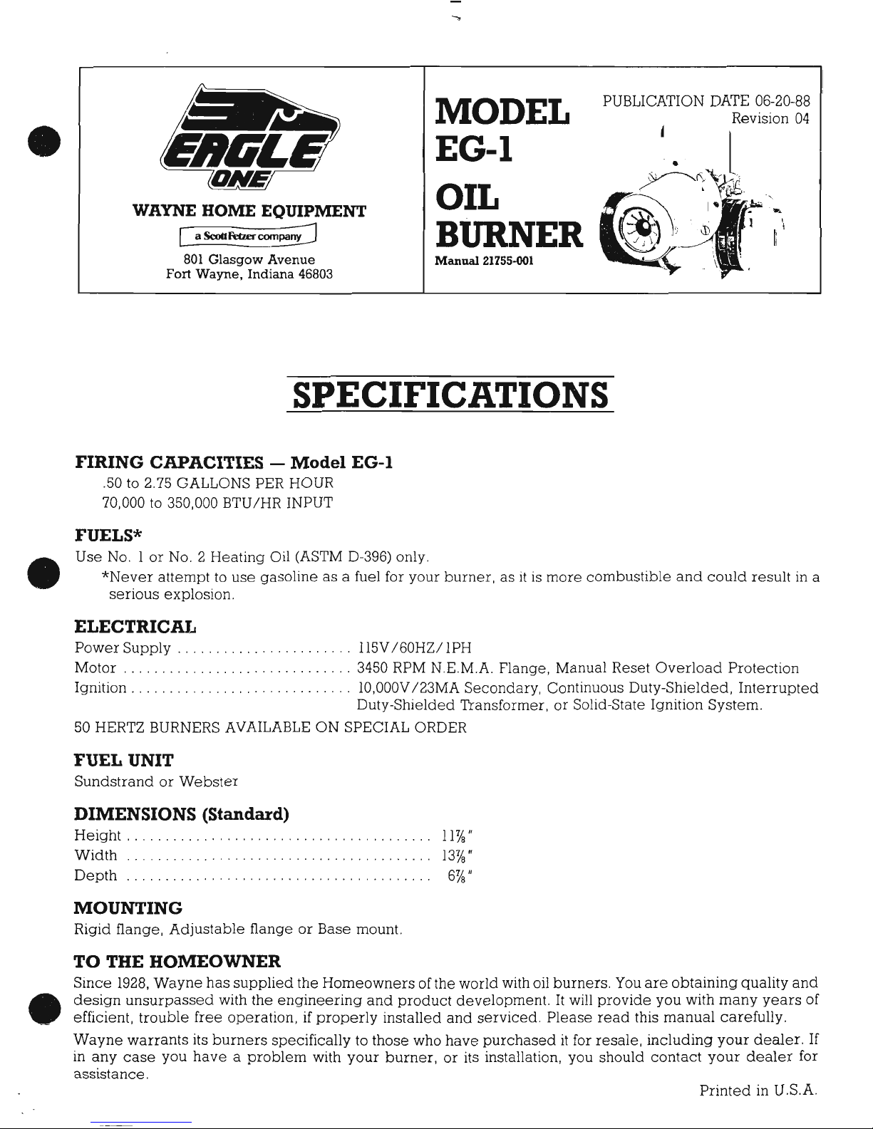
MODEL
EG-I
OIL
BURNER
Manual
21755-001
PUBLICATION
DATE
06-20-88
Revision
04
•
•
SPECIFICATIONS
FIRING CAPACITIES -
Model
EG-I
.50 to 2.75 GALLONS PER HOUR
70,000
to
350,000 BTUIHR INPUT
FUELS*
Use
No.1
or
NO.2
Heating
Oil (ASTM D-396) only.
*Never
attempttouse
gasolineasa fuel for your
burner,asitismore
combustible
and
could
result
in a
serious
explosion.
ELECTRICAl.
Power
Supply
Il5V 160HZI IPH
Motor 3450 RPM N.E.M.A. Flange, Manual Reset
Overload
Protection
Ignition , ,
1O,000V
123MA
Secondary,
Continuous Duty-Shielded,
Interrupted
Duty-Shielded Transformer,orSolid-State Ignition
System.
50 HERTZ BURNERS AVAILABLE ON SPECIAL ORDER
FUEL UNIT
SundstrandorWebster
DIMENSIONS (Standard)
Height
, , . , , , ,.., . , . . ...11Ye"
Width
,."
,.....
13Ye"
Depth
, .
..
6Ye"
MOUNTING
Rigid flange,
Adjustable
flangeorBase mount.
TO THE HOMEOWNER
Since
1928,
Wayne
has
supplied
the
Homeowners
ofthe world with oil
burners.
You
are
obtaining
quality
and
design
unsurpassed
with
the
engineering
and
product
development.Itwill
provide
you
with
many
years
of
efficient,
trouble
free
operation,ifproperly
installed
and
serviced.
Please
read
this
manual
carefully.
Wayne
warrants
its
burners
specifically to
those
who
have
purchaseditfor
resale,
including
your
dealer.
If
in
any
case
you
haveaproblem
with
your
burner,
or
its installation, you should
contact
your
dealer
for
assistance.
Printed
in U.S.A.
Page 2
APPROVI1LS
The
burner is
U,L.
listed
for use
with Group
I or Group
II
primary
safety controls. State
and local
approvals
are shown on burner
rating
label. AII
burners should be
installed in
accordance
with
the National
Fire
Pro-
tection Association,
and
in complete
accordance
with all local codes and authorities
having
jurisdiction.
Regulations of these
authorities
take
precedence
over
the
general
instructions
provided
in this manual.
GENERAL INTORMATION
HEATING PLANT - Before
installing this burner in a conversion installation,
try to
provide
adequate
space to service the burner
properly
when installing for
easy maintenance.
The
heating
system
should
be
narofirllrr irenoniorl
for defects and cleanliness,
if
proper performance
is to
be obtained,
An oil
bUrner is
only a means of supplying heat for the
firebox and from
there
the heating system
must absorb
and
circulate
the
heat.
The
flue
passages
and heat
absorbingt
surfaces must
be clean
to assure maximum
heat transfer to
the furnace
or boiler. Soot
and fly ash act as
insulators,
retarding
the
transfer of heat. All
doors, openings,
and
cracks should be cemented
air-tight to eliminate air
infiltration
into the heating
plant,
causing heat
Iosses,
Inspect
smoke
pipe
and
chimney
for elimination
of leaks
and obstructions. Be
sure of
adequate
chimney
size and height, Install a mechanical draft adjuster,
if need be,
same size as smoke
pipe (see
column
under
"Draft
Regulators").
Warning:
If this burner is equipped
with
a relight type control
it shall not be used
on appliances having
brick,
ceramic, or
castable
refractory
liner
for
combustion chamber. Hazard may
occur on flame failure
because
the flame detector may
see the hot
refractory liner
and not respond
to flame outage,
permitting
prolonged
dolirrorrr nf ,"ril hofr'
:d
fnr an Attornnt tn rolinht tho l-rrrrnor
--,Jre
lgnlllon 1S IeIUrnL*
\v lvrryrr(
COMBUSTION
CHAMBER
The
purpose
of a combustion chamber is to maintarn a high
flame temperature, by reflecting
the heat
back
rnto
the flame. A hiqh
temperature
assures
greater
combustion efficrency
and
lower
stack losses.
An insulat-
inq refractory
or a Fiber Fax type chamber can be used with
this burner. It is rmportant to
select
and
install, if
no.6qqiy\r tho anrrggt
srze chamber on a conversion
job
(see
chart). On the
flamelock
conversion
burners
J
|
lrav vvrr
the atomized
oil
burns
just
cff
the
flalnelock. On ail
oil
burners
the atomized
oii must not touch the sides
or
bottom of chamber, or smoke
lvrll
result
To
eliminate the smoke,
excess
arr
will be required, resulting
in
higrh
stack temperature and
lower combustion effrciency. Install
burner so the face of air
cone of burner is set
%
"
behind the inside froirt
wall
of
the charnber
(see
dragranr). Caution
on
rnstalling Flamelock
burners in
stainless steel chambers
shoujd
be taken, because of the higher temperature levels
produced
by high
per-
formance flame retention burners,
The
terrrpelature
may
exceed the
temperature
ratings
of the
stainless
steel
chamber, ancl can result rn chamber
burn outs. When
you
are replacing a standard burner with
a flame
retention burner, take the follor,vrngr
precautiotrs'
(l)
Use
pliable
combustion chamber to
line
the
inside
of
chamber,
(2)
Ad;ust bur;rer
(Se
e
'Final
AdjLrstrrcnts Column)
FIJHXJ
UNIITS AND OII.,
LINN$
Conversion Burners are
provrcied
wrth a srrigle statie
3450
RPM fuel
rrnrts
,vith
the by-pass
plug
removed
f^-..i-^t^
-.;*^
!".^+-
rur Drirvrs
1-,1-c,rrrtdllaii{ttts.
fl ;s is satishcior',''r'here the f,-rt:l
suunly is on the same level,
or
above
burner,
'^^-*:++;--
--^":r"'lovr
oJ"orl
. N:'.c
r exceecj
3 FST
pre-.sure
tn thc srrcr ion
src.e
of fuei unit.
A
pressure
over
B
fJsrlrrrr.rlir9
9r
dvrry 1
PSI
may cause damage tc the
shait seal ancl allo'ur ri to leai.:
oil. When rt
js
necessary to lrft
the oil to the
burner,
a return Ine
shcLrld
bc
r.in
bet'ruecn
fusl unri :ncl
orl suprply.
(lf
Ifl
e>lceeds
j0
feet. a two stage fuel
unit
nrust
be
used wirh : retLrin
-irre.)
lVli:n a t'i.f
iine;s used,
rire b;'
pass
p.ug
nrust be rnstalled. This
is sup-
nliod rlnrrrr
rr:rth
tho
bUrnel-att;;hed
tO
igel U:trt, alCn,,l
".lilh
an rnilrr,ralr3n
plrrnp
data Sheet in a
plaStiC
bag.
When
oil hnes are installed, cc,nlinrrous
iuns of hea','r,
viaii
copper tubri:g
is recommended
Be sure that
ail
connections
are absoiutely alr-trght Check
all connections and
Jornts,
Flared
fittings are recommended,
Do
not
use compression frttings See
pump
data sheet
ior sizing, lift
and length for tubing
recommendations.
Use
an
oil filter of adequate srze
for all rnstallations.
Instali instde the
building bet,,veen the tank shutoff vaive
and
the
burner.
For ease of servrcing, locate the
shutoff
valve and filter near
the burner.
TANKS
AND PtrPING
Local
codes and
regulations must be adhered to
regarding tank and burner
installation.
WIRING
AII
wiring must compiy
with
the
National Electric Code
and
local ordinances.
Refer to dragram
supplied
with
burner or controls,
making sure the burner
and controls are
wired
correctly
and that the Iine
switch is
properly
fused to burner.
A.IR
SUPPLY
FOR
COMBUSTION
Do not install
in
rooms with lnsufficient air to suppoft combustion. Occasionaily it is necessary to
install win-
dows
or cut
holes
in
a door to these
rooms, to obtarn sufficient air and to
prevent
less than atmospheric
air
pressure
in the room. If there
is a lack of combustion air rn the room, the burner flame will be
yellow
and for-
mation
of soot will occur in the heatir-rg
unit. In buildings of conventional frame,
brick
or
stone
construction
without
utility rooms, basement
ivindows,
or stairs
doors, infiltration
is normally
adequate to
provide
air
for
combustion
and
for
operation
of the barometric draft
control. For
installation
in an
enclosed
utility
room
EG-1 - 21755-00l
Rev. 04/06-20-88
PAGE
2
o
o
b~.Y~E\
APPROVALS
The
burner
is U.L.
listed
for
use
with
GroupIor
GroupIIprimary
safety
controls. State
and
local
approvals
are
shownonburner
rating
label.
All
burners
shouldbeinstalledinaccordance
with
the
National
Fire
Pro-
tection
Association,
andincomplete
accordance
with
all
local
codes
and
authorities
having
jurisdiction.
Regulationsofthese
authorities
take
precedence
over
the
general
instructions
provided
in
this
manual.
•
GENERAL INFORMATION
HEATING
PLANT
-
Before
installing
this
burnerina
conversion
installation,
trytoprovide
adequate
spacetoservice
the
burner
properly
when
installing
for
easy
maintenance.
The
heating
system
should
be
carefully
inspected
for
defects
and
cleanliness,ifproper
performance
is to
be
obtained.
An
oil
burner
is
onlyameansofsupplying
heat
for
the
firebox
and
from
there
the
heating
system
must
absorb
and
circulate
the heat.
The
flue
passages
and
heat
absorbing
surfaces
mustbeclean
to assure
maximum
heat
transfer
to
the
furnaceorboiler.
Soot
and
fly ash act as insulators,
retarding
the
transferofheat.
All
doors,
openings,
and
cracks
should
be
cemented
air-tighttoeliminate
air
infiltration
into
the
heating
plant,
causing
heat
losses.
Inspect
smoke
pipe
and
chimney
for
eliminationofleaks
and
obstructions.
Be
sureofadequate
chimney
size
and
height.
Installamechanical
draft
adjuster,
ifneed
be,
same
size as
smoke
pipe
(see
column
under
"Draft
Regulators").
Warning:
If
this
burner
is
equipped
witharelight
type
controlitshall
not
be
used
on
appliances
having
brick,
ceramic,
or
castable
refractory
liner
for
combustion
chamber.
Hazard
may
occur
on
flame
failure
because
the
flame
detector
may
see the hot
refractory
liner
and
not
respondtoflame
outage,
permitting
prolonged
delivery
of
011
before
ignitionISreturned
foranattempttorelight
the
burner.
COMBUSTION CHAMBER
The
purposeofa
combustion
chamber
is to
maintainahigh
flame
temperature,
by
reflecting
the
heat
back
into
the
flame.Ahigh
temperature
assures
greater
combustion
efficiency
and
lower
stack
losses.
An
insulat-
ing
refractory
oraFiber
Fax
type
chamber
canbeused
with
this
burner.
It is
importanttoselect
and
install,
if
necessary,
the
correct
size
chamber
on a
conversion
Job
(see chart).
On
the
flamelock
conversion
burners
the
atomized
oil
burns
just
eff
the
flarnelock
On
all
OJI
burners
the
atomized
oil must
not
touch
the
sides
or
bottomofchamber,
or
smoke
will
result
To
eliminate
the
smoke,
excess
air
will
be
required,
resulting
in
high
stack
temperature
and
lovver
combustion
efficiency.
InstaJl
burnersothe
faceofair
coneofburner
is set
Yi"
behind
the
inside
front
wallofthe
chamber
(see
diagram).
Cautiononinstalling
Flamelock
burners
in
•
stainless
steel
chambers
shouldbetaken,
becauseofthe
higher
temperature
levels
produced
by
high
per-
formance
flame
retention
burners.
The
temperature
may
exceed
the
temperature
ratingsofthe
stainless
steel
chamber,
and
can
result in
chamber
burn
outs.
When
you
are
replacingastandard
burner
withaflame
retention
burner,
take
the
following
precautions
(1) Use
pliable
combustion
chambertoline
the
inside
of
chamber,
(2)
Adjust
burner
(SEe
"Final
Adjustments"
Column)
FUEL UNITS
AND
OIL LINES
Conversion
Burners
are
provided
V'JIth a sir.qle
st2~;e
3450
RPM
fuel units
with
the
by-pass
plug
removed
for
single
pipe
installatil):1s
Ths
is s2tlcofaclory ',vhere the
flk:l
SUl-.)ply
is on the same
level,orabove
burner,
permitting
gravity
flovv 0
1
0)1
Ne':n
exceed
3
F81
preS"lHetothe suctIon
si~e
of
fuel
unit. A
pressure
over
8
PSI
may
cause
damagetothe shaft sea]
and
allow
i:
10
leak
OIl
\NhenItis
necessarytolift
the
oiltothe
burner,areturn
lIne
should
bE-
run bet\rveen
fLl!:?1
Ulllt
and
oil
supply
(If
11ft
exceeds10feet, a
two
stage
fuel
unit
mustbeused
vvith a
return
lll!e)
When
a t,:"o
lineisw,ed,
the
by-pass
plug
mustbeinst3.11ed.
This
is sup-
plied
along
wlth
the
burner
atii?tchedtofuel
U~1It,
along
'Nith an mkJrrl1al10n
plimp
data
sheet
in a
plastic
bag.
When
oil
lines
are
installed,
cominllous
runsofhea\iY wi'iil
copfjer
tubingISrecommended
Be
sure
that
all
connections
are
absolutely
air-t1gh!.
Check
uJl
connections
and
Joints.
Flared
fittings
are
recommended.
Do
not
use
compression
fittings See
pump
data
sheet for sizing, lIft
and
length
for
tubing
recommendations.
Use
an
oil
filterofadequate
size
for
all installations.
Installlflside
the
building
behveen
the
tank
shutoff
valve
and
the
burner.
For
easeofservicing,
locate
the shutoff
valve
and
filter
near
the
burner.
TANKS
AND
PIPING
Local
codes
and
regulations
mustbeadheredtoregarding
tank
and
burner
installation.
WIRING
All
wiring
must
comply
with
the
National
Electric
Code
and
local
ordinances.
Refertodiagram
supplied
with
burner
or
controls,
making
sure
the
burner
and
controls
are
wired
correctly
and
that the
line
switch
is
properly
fusedtoburner.
AIR
SUPPLY FOR COMBUSTION
Do
not
installinrooms
with
insufficient
airtosupport
combustion.
Occasionally
it is
necessarytoinstall
win-
•
dowsorcut
holesina
door
to these rooms, to
obtain
sufficient
air
andtoprevent
less
than
atmospheric
air
pressureinthe
room.Ifthere
is a
lackofcombustion
air
in the
room,
the
burner
flame
will
be
yellow
and
for-
mationofsoot
will
occur
in the
heating
unit.Inbuildingsofconventional
frame,
brick
or
stone
construction
without
utility
rooms,
basement
windows,orstairs doors,
infiltrationisnormally
adequatetoprovide
air
for
combustion
and
for
operationofthe
barometric
draft
control.
For
installationinan
enclosed
utility
room
EG·'
·21755·001
Rev.
04/06·20·88
PAGE
2
Page 3

without
an outside wall,
a fresh air opening to the
outside with
a free cross sectional
area
of 20 square
inches
nav arnh nrllnn nar
lepl'firing rate is recommended.
For
each
1,000
feet above sea level, increase
the fresh
air
opening by at least four
(4) per
cent. The room
should be
isolated from any
area served
by exhaust fans.
Do
not install
an exhaust fan in this room.
CHIMNEY
Follow
the recommendations
of
the heating
unit manufacturer.
It
must be
properly
designed,
of adequate
size, and
should
be
above
the surrounding objects,
tilelined, with
no obstructions,
and
be in
good
state of
repair. The
smoke
pipe
should
set
flush
with the inside
of tile
and be
cemented
in
place.
All cleanout
doors
should
be sealed.
DRAFT
REGULATORS
The use
of a
draft regulator
is recommended
and should
preferably
be mounted in the smoke
pipe.
Use
a
draft
gauge
to adjust
to
proper
opening. When the burner air
supply and draft is
properly
adjusted,
the com-
bustion
chamber
draft
will
be approximately
.0I
"
to
.02 "WC
and the stack draft
will
be
.02'
to
.04'WC.
The
Iarger
the
installation,
the
greater
the
draft
will be
required
at the stack to obtain
the .0i
"
to
.02'WC
at
the
combustion
chamber.
NOZZLES
Use the
proper
size, type and spray
pattern
nozzle that heater manufacturers
recommend.
In
some
cases
of
upgrading
or
conversion
installations,
the use of 80o Hollow
or Solid
nozzle are
the best to start with.
STARTING
PROCEDURE
STARTING
BURNER
Be
sure main
switch is in
"off"
position,
and be sure
the
thermostat is
substantially above room
temperature,
the
oil tank
is filled, all valves
are open, and
controls set for operation. Adjust air
supply on
burner
by loosening
lockscrew
on outer band, and
open
partially.
Open the
inspection
door and turn
on
switch.
Prime
pump
according
to the
pump
manufacturer's
recommendations and check
pressure.
If safety
lockout
occurs,
reset after
I or 2 minutes. Do not run fuel
unit dry for more than 5
minutes.
When fire
is
established
make a
temporary air adjustment for
clean combustion flame, reduce air supply until flame
tips
appear
slightly
smoky,
then
readjust
so flame tips are
clean iooking.
Leave
inspection door open until
chamber is
dry. When normal
temperatures are reached,
close inspection door and adjust draft regulator.
(See
column under
"Draft
Regulators").
rrNAL
ADIUSTMENTS
At
this
point
a final
adjustment should
be
used
by the use of
a COMBUSTION
TEST KIT. After
operating
l0
minutes to warm up unit,
a smoke tester should
be
used
to take a smoke reading. We are
wanting
no
greater
than
#l
(Shell
Bacarach
scale), less than a
#l
smoke is desired. Some times a new heating unit requires
more
time
than this to burn clean
due to the oil film
on the new heater unit surfaces. Recheck draft and
take a CO,
reading
over
the
fire and in the stack. If a large
differential
between CO, readiners is noted, air leakage
is the
most common
cause
(see
column under
"Heating
Plant").
CO, readings must ali be
taken
ahead of
draft con-
trol. The
CO, measured
in the stack should be at
least
90/of.or oil
rates
1.00
GPH or below, and
be
at
least l0%
for all rates
over
1.00 GPH. Unit should be started and
stopped several times to assure
good
operation. Open
inspection
door,
turn off oil
valve,
and check
out safety
timing
of combustion control. Check operation
of limit
controls
and thermostat.
Check for oil leaks.
Note: All
installations should be
reinspected after
I or 2 weeks
of normal
operation.
rINAL
CHECKS
Be sure
air shutter
and draft control adjustments
are locked, and the controls on heating unit are adjusted
in accordance
with
the heater and Control
Manufacturer's Instruction Sheets.
MAINTENANCE
OILING
MOTOR - By
proper
oiling twice a
year,
the
motor life will be increased; only a few drops
of non-
detergent
type
oil
at
both motor holes are needed.
FILTER
-
The
oil filter cartridge should
be replaced once a
year
so
the fuel oil will
not
become
contami-
nated and
plug
up fuel
pump
and nozzle
of oil burner.
NOZZLE
-
The
nozzle should be changed
at least once each
year
before
the start-up
of the heating
season. Replace
with
proper
nozzle.
COMPONENTS
-
If for any
reason
any of the
burner
parts
have to be
replaced, always use
parts
recom-
mended
by the
manufacturer.
Specify
part
numbers
and description
when
ordering.
(lN
ALL
COM-
MUNICATIONS
STATE
BURNER MODEL AND
SERIAL NUMBERS).
ELECTRODE
SETTINGS
-
This is very important
for reliable
ignition of the
oil;
check these
once a
year
in
accordance
with
the instructions
provided
in
this manual.
FAN
& BLO\IIER HOUSING
-
This must be kept
clean,
free of dirt and
lint; open
transformer to check
fan
blades
from above, Be
sure the
electric
power
is
off on burner
when
the transformer
is
opened up for
this
inspection,
EG-l - 21755-001
Rev.
04/06-20-88
PAGE
3
•
•
•
----------------
..
-----
without an outside wall, a fresh
air
openingtothe outside
with
a free cross sectional
area
of20square
inches
per
each
gallon
per
hour
firing
rate is
recommended.
For
each
1,000
feet
above
sea
level,
increase
the fresh
air
openingbyat least four
(4)
per
cent.
The
room
shouldbeisolated from
any
area
servedbyexhaust fans.
Do
not install an exhaust fan in this
room
.
CHIMNEY
Follow
the
recommendationsofthe
heating
unit
manufacturer.
It must
be
properly
designed,ofadequate
size,
and
should
be
above
the
surrounding
objects,
tile-lined,
with
no obstructions,
andbein
good
state
of
repair.
The
smoke
pipe
should
set flush
with
the
insideoftile
andbecementedinplace.
All
cleanout
doors
should
be
sealed.
DRAFT REGULATORS
The
useofa
draft
regulatorisrecommended
and
should
preferably
be
mounted
in the
smoke
pipe.
Use
a
draft
gauge
to adjust to
proper
opening.
When
the
burner
air
supply
and
draftisproperly
adjusted,
the
com-
bustion
chamber
draft
willbeapproximately
.01" to
.02
"we
and
the stack
draft
will
be
.02" to
.04
"we.
The
larger
the installation, the
greater
the
draft
willberequired
at the
stacktoobtain
the .01" to
.02
"we at
the
combustion
chamber.
NOZZLES
Use the
proper
size,
type
and
spray
pattern
nozzle that
heater
manufacturers
recommend.Insome
cases
of
upgrading
or
conversion
installations, the useof800HolloworSolid nozzle
are
the
best
to start
with.
STARTING PROCEDURE
STARTING BURNER
Be
sure
main
switch
is in
"off"
position,
and
be
sure
the thermostat is
substantially
above
room
temperature,
the
oil
tankisfilled,
all
valves
are
open,
and
controls
set for operation.
Adjust
air
supply
on
burner
by
loosening
lockscrew
on
outer
band,
and
open
partially.
Open
the
inspection
door
and
turn
on
switch.
Prime
pump
according
to the
pump
manufacturer's
recommendations
and
check
pressure.Ifsafety
lockout
occurs,
reset
after1or
2 minutes.
Do
not
run
fuel unit
dry
for
more
than 5 minutes.
When
fire
is
established
makeatemporary
air
adjustment
for
clean
combustion
flame,
reduce
air
supply
until
flame
tips
appear
slightly
smoky,
then
readjust
so
flame
tips
are
clean
looking.
Leave
inspection
door
open
until
chamberisdry.
When
normal
temperatures
are
reached,
close
inspection
door
and
adjust
draft
regulator
.
(See
column
under
"Draft
Regulators").
FINAL ADJUSTMENTS
At
this
point
a final adjustment
shouldbeusedbythe useofa
COMBUSTION
TEST KIT.
After
operating
10
minutestowarmupunit, a
smoke
tester
shouldbeusedtotakeasmoke
reading.
We
are
wantingnogreater
than#1(Shell
Bacarach
scale), less than a#1smokeisdesired.
Some times a
new
heating
unit
requires
more
time
than this to
burn
clean
due
to the
oil
film
on the
new
heater
unit surfaces.
Recheck
draft
and
takeaCO
2
reading
over
the
fire
and
in the stack.Ifa
large
differential
between
CO2readings
is noted,
air
leakage
is the
most
common
cause (see
column
under
"Heating
Plant").
CO2readings
must
allbetaken
aheadofdraft
con-
trol
The
CO2measured
in the
stack
shouldbeat least 9% for oil rates
1.00
GPHorbelow,
andbeat
least
10%
for
all
rates
over
1.00
GPH. Unit
shouldbestarted
and
stopped
several
times to assure
good
operation.
Open
inspection
door,
turn
off
oil
valve,
and
check
out safety
timingofcombustion
control
Check
operationoflimit
controls
and
thermostat.
Check
for
oil
leaks. Note:
All
installations
shouldbereinspected
after1or2weeks
of
normal
operation.
FINAL CHECKS
Be
sure
air
shutter
and
draft
control
adjustments
are
locked,
and the
controlsonheating
unit
are
adjusted
in
accordance
with
the
heater
and
Control
Manufacturer's
Instruction
Sheets.
MAINTENANCE
OILING
MOTOR
- By
proper
oiling
twiceayear,
the
motor
life
willbeincreased;
onlyafew
dropsofnon-
detergent
type
oilatboth
motor
holes
are
needed.
FILTER -
The
oil
filter
cartridge
shouldbereplaced
onceayearsothe fuel oil
will
not
become
contami-
nated
and
plug
up
fuel
pump
and
nozzleofoil
burner.
NOZZLE -
The
nozzle should
be
changed
at least
once
each
year
before
the start-upofthe
heating
season.
Replace
with
proper
nozzle.
COMPONENTS
-
If
for
any
reason
anyofthe
burner
parts
havetobe
replaced,
always
use
parts
recom-
mended
by
the
manufacturer.
Specify
part
numbers
and
description
when
ordering.
(IN
ALL
COM-
MUNICATIONS
STATE BURNER
MODEL
AND
SERIAL NUMBERS).
ELECTRODE SETTINGS - This is
very
important
for
reliable
ignitionofthe oil;
check
these
onceayear
in
accordance
with
the instructions
providedinthis
manual
FAN
&BLOWER HOUSING - This must
be
kept
clean,
freeofdirt
and
lint;
open
transformertocheck
fan
blades
from
above.
Be sure the
electric
powerisoffonburner
when
the
transformerisopened
up
for
this
inspection.
EG·1
·21755·001
Rev. 04106-20-88 PAGE 3
Page 4

ATTACHING
AIR
TUBE
COMBINATIONS
TOR
CIIASSIS
PI,AN
ONI,Y
When oil
burner chassis
and air
tube
combination
are
packed
separately,
the
burner
must be assembled
as follows:
l-
Lay
burner
chassis on
its
back
as shown
at right.
Insert
air tube into
burner
chassis
lining up the 3 holes in the chassis with
the
3 holes in the
air tube.
Install the 3 screws
s/s
long and secure.
2- Install
proper
nozzle
into
gun
assembly.
Loosen
and remove the two
screws located on the transformer top
plate
at
the front of
the burner
chassis and swing
open.
Slide drawer assembly
into air
tube
(see
Fig. 2).
3-
Once installed, adjust
grun
assy., either back
or forward to
position
nozzle
from
head, For
correct
positioning (see
Fiq.
3).
Secure the
slide
plate
by
tightening
thumb screw at side of housing.
Attach flared nut of Oil
Line
Assy.,
(Copper
Oil Line) to the end of this adapter
fitting as shown.
Install
arrow decal as shown so
position
of Drawer
Assy. is always known
(see
Fiq. 4).
Recheck for nozzle
centering before burner is installed
(see
Fig, l).
Make
sure
electrode tips ciear retention head.
INSERT
"SE'' SERIES GUN SETTING GAUGE
(AS
SHOWN
EELOW) TO CHECK NOZZLE
POSITION
AND ELECTRONIC SETTING.
Figure
3
ELECTRODE
BURNER AIR TUBE
NOZZLE
FLAMELOCK CONE
"sR" SEFTES
GUN SETTING GAUGE
ALL DIM'S
AS SHOWN UNLESS OTHEFWISE SPECIFIED
'/a
"
t/8"
BURNER
OIL
PIPE
BURNER AIR TUBE
4%
FLAMELOCK
HEAD
NOZZLE FACE TO FACE OF INNER AIR CONE
TRACK
FOR
GUN
ASSEMBLY
AOJUSTMENT BRACKET
Figure
1
t/2"
Figure 2
EG-l - 21755-001
Rev. 0406-20-88
PAGE
6
ATTACHING AIR TUBE COMBINATIONS FOR CHASSIS
PLAN
ONLY
When
oil
burner
chassis
and
air
tube
combination
are
packed
separately,
the
burner
must
be
assembledasfollows:
1-
Lay
burner
chassis on its
back
as shown at right. Insert
air
tube
into
burner
chassis
liningupthe 3 holes in the chassis
with
the 3
holes
in the
air
tube.
Install
the 3
screws%long
and
secure.
2-
Install
proper
nozzle into
gun
assembly. Loosen
and
remove
the
two
screws
located
on the
transformer
top
plate
at the frontofthe
burner
chassis
and
swing
open. Slide
drawer
assembly
into
air
tube
(see Fig.
2).
3-
Once
installed.
adjust
gun
assy.,
either
backorforward
to position nozzle
from
head.
For
correct
positioning
(see Fig.
3).
Secure the
slide
plate
by
tightening
thumb
screwatsideofhousing.
Attach
flared
nutofOil
Line
Assy.,
(Copper
Oil
Line) to the
endofthis
adapter
fittingasshown.
Install
arrow
decalasshownsopositionofDrawer
Assy. is
always
known
(see Fig.
4).
Recheck
for nozzle
centering
before
burnerisinstalled
(see Fig.
1).
Make
sure
electrode
tips
clear
retention
head.
•
Figure 1
INSERT
"SR"
SERIES GUN SETTING GAUGE
(AS SHOWN BELOW) TO CHECK NOZZLE
POSITION AND ELECTRONIC SETTING.
•
1(2--
II
~
-£1/8
L1
cHB:1~w
~~
-
~~I(B"
FLAMELOCK HEAD
ELECTRODE
FLAMELOCK CONE
"SR"
SERIES
GUN SETTING GAUGE
~
ALL
DIM'S AS SHOWN UNLESS OTHERWISE SPECIFIED
NOZZLE FACE TO FACE
OF
INNER AIR CONE
NOZZLE
TRACK FOR GUN ASSEMBLY
ADJUSTMENT BRACKET
~-+_
GUN ASSEMBLY
ADJUSTMENT BRACKET
BURNER
AIR
TUBE
DECAL--==tr:r-
ELECTRODE SUPPORT
Figure 2
EG·1
. 21755-001
Rev.
04106-20-88
PAGE
6
Page 5
tsURNER
COI\TPONENTS
IVIODEL
EG-l
@-
ST'JTTE
BURT{HR
g{ODEL,
PJIX,IT
DESC;IIPYS.$H
ATTO P,|IA.T
NTMAEER liT}IEN
ORDERING PJT,RTS
4d
-r
@
-\,
v_/
I
I
&,
@
'@
lIO. USSCRIT},TIOII
FSfi,T
-lT'*.
1 _9!l!!Iri?9si,1c,
1l!30!!!l
2 JUNCTION
BOX
21419-SEI1
3
MOTCR
1/s
L
P
2C327
a
_B_!9l.Ell{fitli_
__,
_____}:!ry
5
MO]-OR
COnD
COVER
i3029
6
TFANSFGRMER
21659
7 COUPLING-SMALL
PUMP
13424
8 FUEL UNIT
MODEL-A
13495
FUEL
UNIT
MODEL.B
13634
9 OUTLET
FITTING
13494
10 OIL LINE ASSEMBLY
14451
11 INNEB AIR
BAND
21917-001
12
OUTER
AIR BAND-8 HOLE 21918.001
12A
OUTER AIR
BAND-4 HOLE
21921-001
13
HOUSING
COVER
ASSY. 21908.001
f;7^
-_---D,If.'-"'rilffi
'*
s$',gctr}"Y il,llt TU$E it G'iili
P.ERT
FIIIF/IBSR
SEE iltg,cE
plilt'J
l,ic.
2172,1'OO1
2794-Al1
J[$SY.
CoIwSSil"RTIr)H
R
| " t arn rr rnr- o /
i
r.r
^:n
rL/r,r .r dUi'l
ASSY.
i
r.i nii r
I uLri
(l
uvt\ ,'1.Jt
I COlvlBiii,iillOiJ
L
I
r: ADJLISTABLE
FiAt\tcE
--
I
r6_PEpLSItLU!!Ur_
Suggested
Combustion Chamber Dirnensions
Conversion or Upgrading
Chamber Dirnensions
(In
Inches)
Firing
Square
Bound Height Floor
Rate
to
(G.P.H.)
Width Length Nozzle
.50
7
7
8 11 5-6
.75889',t25-6
.85
81/z BVz
9
12
5-6
1.00
9 9
101/a
121/z
5_6
1 .25
.t
0 1 0
j
11/a
121/z
5_6
1.35
101/z
101/z
113/o
123/a
5_6
1 .S0
1
.1
1 1 123/e 13 5-6
1.65
111/z 111/z 13 131/e 5-6
2.00 12s/s 125/e 141/q 131/z 6-7
2.50 141/q
141/q 16
14 7_8
=G-1
-
21755-001
Fev.
0.1/06-2t-3.c
F.iCE 7
/--
@
:o-----®
®
\
~,,;
®
< I
"
CD
/
®
@-------------------
..
@-
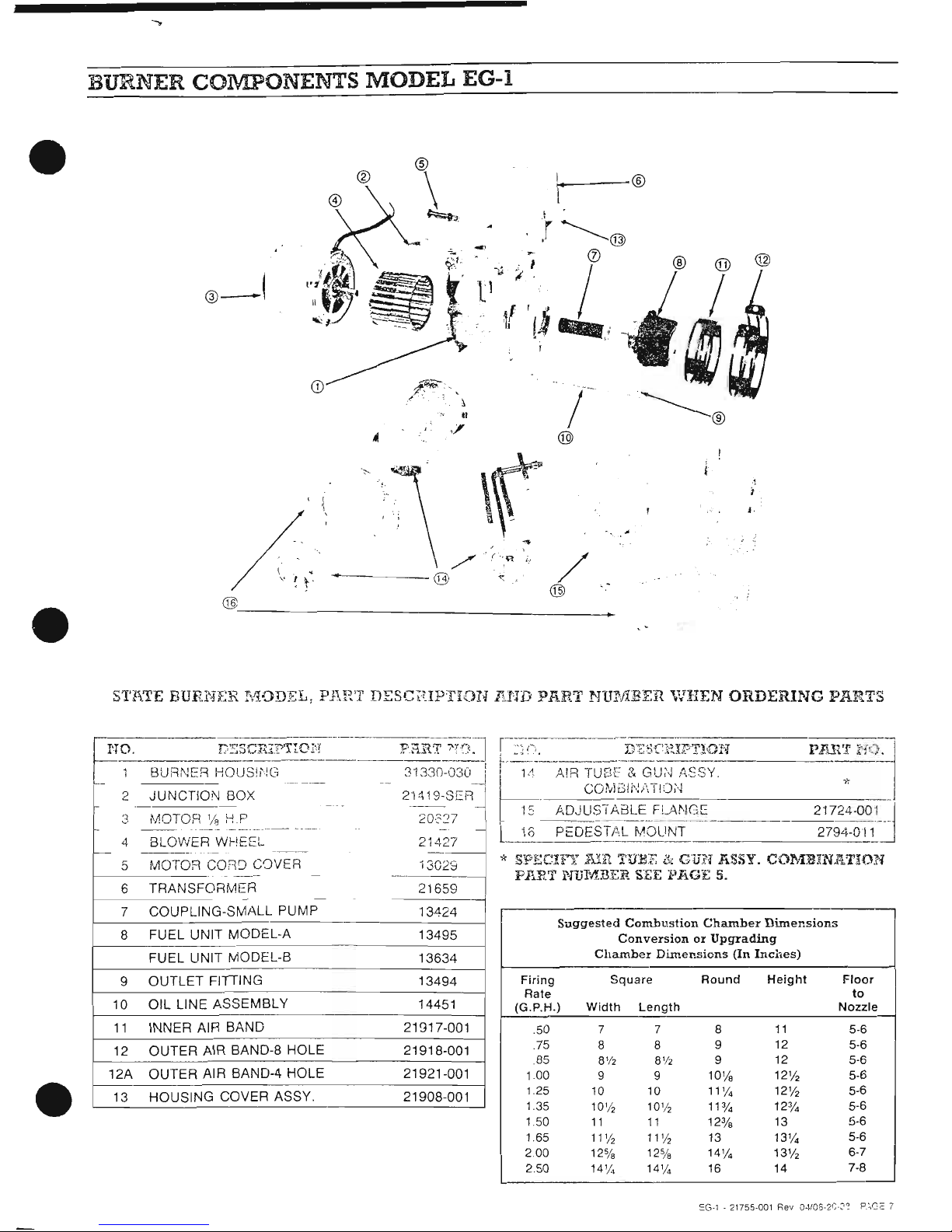
BURNER COlVIPONENTS MODEL EG-l
•
•
STFI.TE
BUR.NER I\10DEL,
PJ\l~T
DESCIUPTION
lU'JD
PllRT
NUMBER
'VHEN
ORDERING
PARTS
•
I I
, J
..,
~
, ,
-
L-.
..
_.-._--
.
---"
------
2
JUNCTION
BOX
2'1419-SER
1----
-
- -
--
.
-
2
MOTOR
1/
8
HP
20'2::'7
--
.
__
._--.--
----
4
BLOWER WHEEL 21427
-
-----
-----
5
MOTOR
CORe>
CaVER
13029
6
TRANSFORMER
21659
7
COUPLING-SMALL PUMP
13<124
8
FUEL UNIT MODEL-A
13495
FUEL UNIT MODEL-S
13634
9
OUTLET
FiniNG
13494
10
OIL LINE ASSEMBLY 14451
11
INNER AIR BAND
21917-001
12
OUTER
AIR BAND-8 HOLE
21918-001
12A
OUTER AIR BAND-4 HOLE 21921-001
13 HOUSING COVER ASSY.
21908-001
r-
jl~:-------D·'S:;C'?XP'T10N
p~{'J
I'j.t)J·
r----·--------
1'1.
AIR
TUEH:
&
GU~'J
(,.SSY.
Cm,iGIi'U\TI<XJ
'*
15
ft,DJUSi
AaL~
__
F!.J\1'!G_~
21724'001_j~
13 PEDESTAL
MOUNT
2794-011
-----_.
*
SPECln:
run
'HIEF.
&:
Gun
liSSY.
C01\flHNAT:!DN
PART
N1J"MRER
SEE
PliGE
5.
Suggested
Combustion
Chamber
Dimensions
ConversionorUpgrading
Chamber
Dimensions
(In
Inches)
Firing
Square
Round
Height
Floor
Rate
to
(G.P.H.)
Width
length
Nozzle
.50 7 7 8
11
5-6
.75
8 8
9
12 5-6
85
8'12 8'12
9
12 5-6
1.00
9
9
10'/8
12%
5-6
1.25
10
10
11'1.
12%
5-6
1.35
10'/2 10'/2
1131.
12
3
/.
5-6
1.50
11 11
12
3
/8
13 5-6
1.65
11
'12
11'/2
13 13'1.
5-6
2.00
12%
12%
14'/.
13%
6-7
2.50
14'1. 14'1.
16
14 7-8
=G-l
·21755-001
Rev
O-lt06-2~-::~
P.~Gc
7
 Loading...