

Page 1

Operation
DW-10 and DW-12 Dispenser Printers
P/N 000-920921Rev D
Page 2

READ THIS MANUAL BEFORE YOU BEGIN
Dispensers have both electricity and a hazardous, flammable and potentially explosive
liquid. Failure to follow the below precautions and the Warning and Caution instructions in
this manual may result in serious injury . Follow all rules, codes and laws that apply to your
area and installation.
SAFETY PRECAUTIONS
Make sure that you know how to turn OFF power to the dispenser and submersible
pumps in an emergency.
Be sure to adhere to the list of cautions contained in this manual for the DW-10 and
DW-12 printers.
HOW TO CONTACT WAYNE
Trouble with the operation of the printer should be referred to your authorized Wayne service personnel or the Wayne Help Desk (1-800-289-2963).
Page 3

Contents
Title Page
1 Introduction 1
1.1 Paper Type 1
2 Printer Operation 3
2.1 Controls and Indicator Lights 3
2.2 Opening/Closing Printer Door 4
2.3 Loading Paper 5
2.4 Internal Components Clearing Paper Jams 7
2.5 Setting the Paper Width Adjust Lever 7
2.6 Low Paper Sensor Position 8
3 Error Lights and Paper Jams 9
3.1 Error Lights 9
3.2 Clearing Paper Jams 10
4 Safety Precautions 12
5 Service Technician Information 14
5.1 DIP Switch Settings 14
5.2 Component Locations 15
5.3 Tech Tip 16
5.4 Printer Part Numbers 16
_____________________________________________________________________________________i
P/N 000-920921- Rev 0D 04/2015
Page 4

ii____________________________________________________________________________________
P/N 000-920921- Rev 0D 04/2015
Page 5
1 INTRODUCTION
This manual explains the operation of Wayne DW-10 and DW-12 thermal printers used
in Wayne Vista™ and Ovation™ fuel dispensers. The manual contains typical operator
procedures, which incl udes loading paper, use o f the proper paper, cleari ng paper jams
and a list of printer precautions. The manual al so contains a section on service for
Wayne certified technicians.
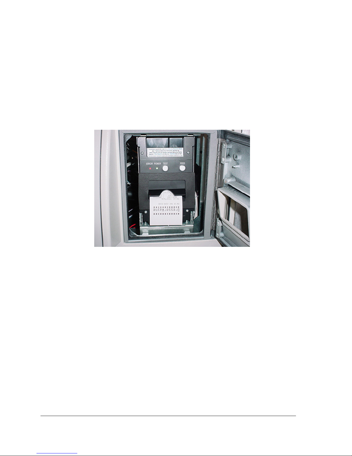
Once the printer door on the dispenser is unlocked and opened, the printer will appear
as shown in the photo below.
1.1 Paper Type
The recommended paper is the Wayne thermal printer paper, part nu mber 7000701 for
1 Roll and part nu mber 700070 3 for a box of 48 Rolls. Paper used in the print er shoul d
comply with specifications of the Wayne paper.
Other printer papers that meet our paper specification include Kansaki P-350 and
Koehler KT55F18 papers with the following:
Inside Core Diameter .68"-.79"
Core Annular Thickness .10"-.28"
Paper and Core Width 2.32"-2.36"
Finished Roll Diameter 3.80"-4.00"
Paper should not be stuck to the core with adhesive.
See cautions concerning paper types on the next page.
_____________________________________________________________________________________1
P/N 000-920921- Rev 0D 04/2015
Page 6

1.2 Paper Type, continued
Adhere to the cautions below when using or when storing the paper.
Caution:
Avoid allowing the surface of the paper to contact with chemicals or oils as
this may cause the paper to become colored or the printed data on it may
become erased.
Avoid scraping on the paper surface with your nail or a metal object as this
may cause the surface of hea t-sensitive paper to become colored.
Do not expose the paper to the effects from heat, humidity, or sunlight as
heat-sensitive paper starts getting colored at approx. 70 degrees.
2____________________________________________________________________________________
P/N 000-920921- Rev 0D 04/2015
Page 7

2 PRINTER OPERATION
2.1 Controls a nd Indicator Lights
* HEXADECIMAL DUMP mode:
If the TEST button is pressed and held for more than 10 seconds, printer will switch to
HEX-DUMP mode.
POWER light starts flashing a nd all r e c eived data will be printed as hexadecimal codes.
To exit the HEX-DUMP mode, press the TEST button briefly and release.
PRINTER INFO:
When the printer door is opened and then closed, the Wayne print out shown above is printed.
This printout includes printer Model name, Firmware version, baud rate, DIP switches, and
built-in fonts.
Front Door Pull
Down Handle
Paper Exit
ERROR Light
Red light is on steady
or blinks to show
different errors.
POWER Light
Green light is on
steady when printer
FEED Button
Feeds paper while
button is pressed.
TEST Button
Prints test receipt
with pump CAT data or
printer info depending
on which is being
received when button
is pressed.
*
_____________________________________________________________________________________3
P/N 000-920921- Rev 0D 04/2015
Page 8

2.2 Opening/Closing Printer Door
1. At the top of the printer, pull the front door handl e down to open the printer
door as shown below.
2. Push the printer door up and close until a click is hea rd which locks the
door. The printer will then begin the test print.
Printer door closed position
Printer door open position
4____________________________________________________________________________________
P/N 000-920921- Rev 0D 04/2015
Page 9

2.3 Loading Paper
Follow the instructions below and refer to the photos on the next page for
loading paper.
1. Unlock and open the bezel printer access door on the front of the dis penser.
2. Pull down the print door.
3. Remove old paper core.
4. Insert a paper roll with paper feeding from the top of the roll as shown in the
photos and pull out the paper.
5. Insert the paper in the pape r inlet as shown and the paper will feed several
cm automatically.
6. Push up the printer door until a click is heard.
7. Close and lock bezel pr i nter access door.
_____________________________________________________________________________________5
P/N 000-920921- Rev 0D 04/2015
Page 10

LO ADING PAPER
Bezel Printer Door Lock
6____________________________________________________________________________________
P/N 000-920921- Rev 0D 04/2015
Page 11

2.4 Internal Components
* With power on, the paper feeds automatically when inserted into the paper inlet.
2.5 Setting the Paper Width Adjust Lever
The printer is set to 60mm paper width when shipping. Wayne supplied paper is 60mm.
If the 58 mm paper width is used, adjust the paper width lever as shown below.
Auto cutter
Paper supporter
Chute Access Door
Paper width adjust lever
*Paper manual
Feed Gear
Paper Inlet
Paper holder
Paper width adjust lever
Head up lever
_____________________________________________________________________________________7
P/N 000-920921- Rev 0D 04/2015
Page 12

2.6 Low Paper Sensor Position
Position
Paper diameter
Length of the remaining paper
1
About 23.5
Not used
2
About 28.0
About 2 meters
3 Default Setting
About 33.0
About 6 meters
4
About 37.5
About 11 meters
The printer has adjustable paper near end (low paper) sensor. Set the sensor to the
appropriate position depending of the paper roll core diameter and the length of the
remaining paper when you wish to be notified of the low paper. The factory sett ing is the
position 3 default is the factory setting.
3 ERROR LIGHTS AND PAPER JAMS
3.1 Error Lights
Below is a description of the detected symptoms that are listed in Table 3-1 on the following
page:
Paper end:
Paper empty is detected in two steps: paper end and paper near end.
In either case, the ERROR lamp is lit. If paper end is detected, replace the paper roll.
Front door open:
If the printer door is opened accidentally, the ERROR light will go on and the print will be
continued even though the door is opened.
Head up:
The ERROR light blinks when the Head Up lever is lowered while printing. The lever should
be in the up position after clearing a jam. The print restarts automatically. The ERROR light
goes to the On state if the lever is lowered.
Thermal head over heat:
When pr inting dense characters or dark images, the head temperature rises. If the head
temperature exceeds a specified level, the printer stops printing and waits until the head
temperature cools off. During waiting, the ERROR light blinks slowly. When the head
temperature goes back to normal operating range, printing resumes automatically.
1
2
3
4
8____________________________________________________________________________________
P/N 000-920921- Rev 0D 04/2015
Page 13

Cutter lock:
If the auto cutter blade stops operating due to a jam, the ERROR light blinks. Clear the jam
and press the FEED button. If the blade does not move, refer to section 3.2.
Paper jam:
When paper is fed 3 inches, the receipt sensor detects it. After the paper is cut, it is
determined to be a jam when the paper doesn't reach the sensor position at that time.
The printer memorizes whether there is paper on the receipt sensor when the print begins.
Table 3-1 Power light and Error light for detected symptoms
Symptom Detected
POWER Light Status ERROR Light Status
Paper end
ON
ON
Paper near end ON ON
Front door open ON ON
Head up ON ON
Head up *1 ON Blinking
Head overheat ON
Slow blinking
Cutter lock ON
Paper jam
ON
Memory check error*2
Quick blinking OFF
Low voltage error*2 ON
High voltage error*2 *3 ON
*1 Head up while the printer is printing.
Indicates two short blinks and a long blink
*2 Requires power cycle to clear error.
*3 Hig h voltage or excessive current. This error indicates electrical problem, head jammed or
head too cold. Most commonly seen at install/startup during very cold conditions.
_____________________________________________________________________________________9
P/N 000-920921- Rev 0D 04/2015
Page 14

3.2 Clearing Paper Jams
If paper exit is blocked, the paper is bent and stored in the paper chute. Three receipts will
be stored in the chute before a jam occurs.
Follow the steps below and the numbered photos on the adjacent page to clear a paper jam:
1. Open the printer door. 1
2. Open the paper chute access door by pressing the door towards the rear with both
thumbs. 2 and 3
3. Remove the jammed paper. 4 and 5
4. Close the paper chute access door and the auto cutter mechanism should initialize and
the alarm should clear. Reload paper. 6
5. If the auto cutter is jammed with paper or any other reason, press the FEED button first.
6. If the auto cutter error continues, turn the cutter gear manually as shown below.
CAUTION:
The print head is hot immediately after printing. Do not touch
.
Note: If the print head is jammed, open the print head as shown above and wipe off
any debris on the heating element of the head using a cotton swab.
CAUTION:
The print head is hot immediately after printing. Do not touch.
Cutter gear
Rotate direction
Head up lever
Print head
Chute access door
10____________________________________________________________________________________
P/N 000-920921- Rev 0D 04/2015
Page 15

3.2 Clearing Paper Jams, continued
1 4
2 5
3 6
_____________________________________________________________________________________11
P/N 000-920921- Rev 0D 04/2015
Page 16

4 SAFETY PRECAUTIONS
Before using this printer for the first time, carefully read these “Safety precautions”.
Incorrect operation may result in unexpected accidents (fire, shock, or injury).
Neglecting the warnings below may result in printer failure, overheating, emission of smoke,
fire, or electric shock.
Warnings:
Do not use this printer other than for its intended application in the dispenser.
Do not use or store this product in place where it will be exposed to:
Flames or moist air
Direct sunlight
Hot airflow or radiation from a heating device
Reactive chemicals
Airborne oil, steel particles, or dust
Static electricity or strong magnetic field
Do not drop any foreign object or spill liquid into the printer. Do not place any object on
the printer. A metallic foreign object, if accidentally dropped into the printer, may cause
printer failure, fire, or electric shock.
Do not handle the printer in the following ways:
Do not allow the printer to sustain strong impacts, e.g., dropping, striking with a hard
edge.
Never attempt to disassemble or modify the printer.
Use or store the printer out of the reach of children.
Electric appliances could cause an unexpected injury or accident if they are handled
or used improperly.
Please observe the following precautions for power source and power cord:
Do not plug or unplug the power cord with wet hand.
Check to make sure that the supply outlet from which the printer is powered has a
sufficient capacity. An overload may cause the power cord to overheat or fire or the
circuit breaker to trip.
Do not move the printer while the printer power is on.
Do not attempt to modify the power cord.
12____________________________________________________________________________________
P/N 000-920921- Rev 0D 04/2015
Page 17

Cautions:
Do not use the printer under conditions where the printer ventilation holes are blocked, where
any object is placed on the printer or where the printer is covered
or wrapped by a cloth or
other materials.
The printer may have an adverse effect on nearby radio or TV transmissions.
There may also be cases when nearby electrical appliances adversely affect t
he printer,
causing data errors or malfunction.
Avoid using the printer near a radio or TV set or supplying it from the same outlet as these
appliances.
Avoid using the printer interconnected with a cable or cord that has no protection against
noise.
Avoid using the printer with a device that is a strong source of noise.
Use the printer with its grounding post connected to an appropriate grounding facility.
Before connecting or disconnecting the grounding lead to or from the printer, always unplug it
from supply outlet.
If leakage occurs electric shock may result.
Do not connect the grounding post onto any of the following facilities:
Utility gas piping. (A gas explosion could result.)
Telephone line ground
Lighting rod
Utility water pipes (Plastic water pipes should not be used for grounding.)
To prevent possible malfunction or failure, observe the following.
Avoid operating the printer without paper properly loaded.
Avoid the use of paper not complying with specifications.
Avoid using torn pieces of paper or spliced with plastic adhesive tapes.
Avoid forcibly pulling already loaded paper by hand.
Avoid wedging the paper in by the paper cover or others.
Avoid using a sharp pointed device to operate panel keys.
Be sure to firmly insert the cable plug into its mating socket.
A cross connection may damage the printer ’s internal electronics or the host system’s
hardware.
To prevent injury and further printer failure, observe the following:
Do not touch the printing surface of the thermal head. The thermal head is at a dangerously
high temperature immediately after printing
Do not touch any of moving parts (e.g., paper cutter, gears, active electrical parts) while the
printer is working.
In case of trouble, do not attempt to repair the printer. Refer to you qualified service personnel.
Caution:
When cleaning the printer, use a soft, dry cloth for cleaning the front surface of the printer door.
For severe stains, use a soft cloth slightly dampened with water. Never use organic cleaning solvent
such as alcohol, paint thinner, trichloroethylene, benzene, or ketone. Never use a chemically
processed cleaning cloth. To remove paper chips, use a soft brush.
_____________________________________________________________________________________13
P/N 000-920921- Rev 0D 04/2015
Page 18

5 SERVICE TECHNICIAN INFORMATION
The information in this section is provided for Wayne certified service technicians only.
5.1 DIP Switch Settings
DIP switches are on the control board as shown below . Turn off the power b efore setti ng DIP
switches.
The function of each switch is as follows:
Switch No.
Function
ON
OFF
Initial Settings
1
Auto Cut
Enabled
Disabled
ON
2
Hand shake
XON/XOFF
DTR/DSR
ON
3
Bit length
7 bits
8 bits
OFF
4
Parity check
With parity
None
OFF
5
Parity selection
Even parity
Odd parity
OFF
6
Baud rate selection See T abl e below
ON
7
ON
8
Print density selection
Dark
Standard
OFF
Baud rate selection
Baud rate (bps)
Switch No.
6
7
9600
OFF
OFF
19200
ON
OFF
38400
OFF
ON
115200
ON
ON
Note:
For dispensers with QCAT board, set Switch 6 to OFF and Switch 7 to ON (38400 Baud rate).
For dispensers with iX board, set Switch 6 to ON and Switch 7 to ON (115200 Baud rate).
8 7 6 5 4 3 2 1 ON
14____________________________________________________________________________________
P/N 000-920921- Rev 0D 04/2015
Page 19

5.2 Component Locations
Data
Connector
Power suppl y
Connector
Main control board
Rear Side
Auto cutter
Out of Paper
Sensor
Head-up lever
Receipt sensor
Front Door Open Sensor
Low Paper Sensor
Paper supporter
Chute Access Door
Paper adjust lever
Paper manual
Feed Gear
Paper Inlet
Paper holder
Print Head
_____________________________________________________________________________________15
P/N 000-920921- Rev 0D 04/2015
Page 20

5.3 Tech Tip
When replacing the DW-10 or DW-12 printer on 4/Vista™ dispensers, the printer door must be
fully opened before securing the printer bracket to the bezel mounting screws. This will allow
the printer to rise up slightly and the top screws should grip the bracket properly. Note that if
the 4/Vista fixed mount printer is allowed to drop down too low on the top screws, paper
loading will not be possible because the printer door will not fully open.
5.4 Printer Part Numbers
DW-10 Printer P/N 890477-001
DW-12 Printer P/N WU005878-0001
16____________________________________________________________________________________
P/N 000-920921- Rev 0D 04/2015
Page 21

OPERATION MANUAL
DW-10 and DW-12 Dispenser Printers
© 2015 Wayne Fueling Systems.
Printed in the United States of America.
This manual and any software described herein are furnished under the terms of sale or other applicable contract
including any license, and may be used or copied only in accordance with those terms.
No part of this publication may be electronically or mechanically reproduced, stored in a retrieval system, or
transmitted, in any form or by any means, except as permitted by such terms. Translation of this material to
another language without express written permission from Wayne Fueling Systems is prohibited.
This publication is intended for informational purposes only and this material is subject to change without notice.
Wayne Fueling Systems has not made, and does not make, any representations or warranties of any kind,
expressed or implied, with respect to any informat ion in the publication, includin g a ny warranty as to the accuracy ,
correctness, or completeness of any of the information. Wayne Fueling Systems shall not be responsible or liable
for any damages or losses that occur as a result of the receipt and/or use of the information contained herein.
Wayne and the Wayne logo are trademarks or registered trademarks of Wayne Fueling Systems, in the United
States and other countries. Other names are for informational purposes and may be trademarks of their
respective owners.
Wayne is located at 3814 Jarrett Way, Austin TX 78728.
Wayne’s general telephone number is (512)-388-8311
Page 22

This product complies with Part 15 of the FCC rules and regulations. Operation is subject to the following
two conditions: (1) This produ c t may not cau se h armf ul int er f erenc e, and (2) this product must accept any
interference received, including interference that may cause undesired operation.
Note: This equipment has been tested and found to comply with the limits for a Class A digital device as
set forth in Part 15 of the FCC Rules. Those limits are designed to provide reasonable protection against
harmful interference when the equipment is operated in a commercial environment. This equipment
generates, uses, and can radiate radio frequency energy, and if it is not installed and used in accordance
with the instruction manual, it may cause harmful interference to radio communications. Operation of this
equipment in a residential area is likely to cause harmful interference, in which case you will be required
to correct the interference at your own expense.
Modifications: Any modifications made to this product that are not approved by Wayne Fueling Systems
could void your authority to operate this equipment.
Wayne Manufacturing Centers
Wayne U.S.
Wayne Fueling
Systems LLC
3814 Jarrett Way
Austin, TX 78728
USA
Wayne China
Dresser Wayne Fuel
Equipment
(Shanghai) Co. Ltd
1221 Dong Lu Road
Pudong, Shanghai
China
Wayne Sweden
Wayne Fueling
Systems Sweden AB
Hanögatan 10
Box 50559
SE-202 15 Malmö
Sweden
Wayne Brasil
Wayne Industria e
Comercio Ltda
Estrada do Timbó
126 - Higienópolis
Rio de Janeiro,
Brasil
© 2015 Wayne Fueling Systems P/N 000-920921- Rev 0D 04/2015
 Loading...