

Page 1
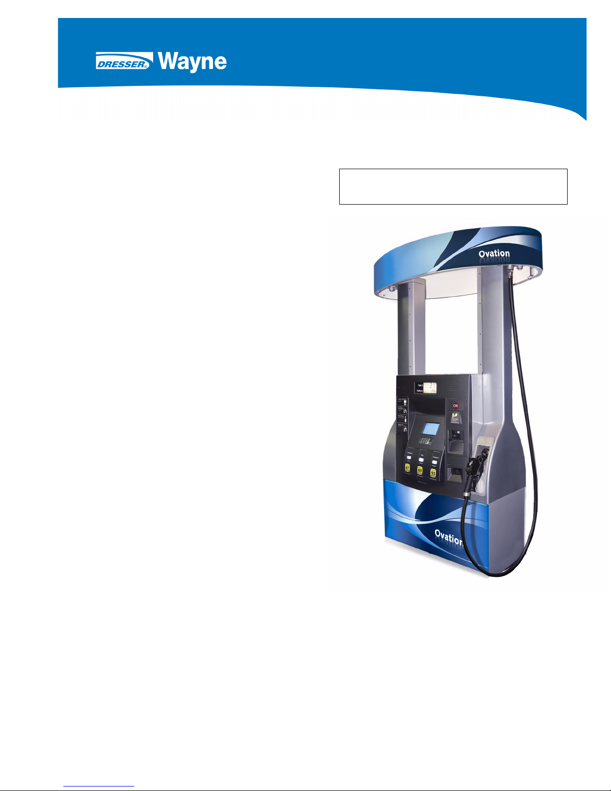
Ovation Dispensers
INSTALLATION
OPERATION
Page 2

DANGER
READ THIS MANUAL BEFORE YOU BEGIN
Dispensers have both electricity and a hazardous, flammable and potentially explosive liquid.
Failure to follow the below precautions and the Warning and Caution instructions in this manual
may result in serious injury. Follow all rules, codes and laws that apply to your area and installation.
SAFETY PRECAUTIONS - INSTALLATION AND MAINTENANCE
Always make sure ALL power to the dispenser is turned OFF before you open the dispenser cabinet for maintenance. Physically lock, restrict access to, or tag the circuit breakers you turn off
when servicing the dispenser. Be sure to trip (close) the emergency valve(s) under the dispenser
BEFORE beginning maintenance.
Make sure that you know how to turn OFF power to the dispenser and submersible pumps in an
emergency. Have all leaks or defects repaired immediately.
EQUIPMENT PRECAUTIONS
Be sure to bleed all air from product lines of remote dispensers and prime suction pumps before
dispensing product, otherwise, damage to the equipment may occur. Always use the approved
method for lifting the dispenser. Never lift by the nozzle boot, sheet metal, valance, etc., otherwise equipment damage or personal injury may occur.
HOW TO CONTACT WAYNE
Technical questions related to the installation of the dispenser should be referred to Wayne
Technical Support (1-800-926-3737). Customers needing help with the operation of the dispenser should call the Wayne Help Desk (1-800-289-2963).
INDICATORS AND NOTATIONS
DANGER
WARNING
CAUTION
NOTE:
Danger indicates a hazard or unsafe practice which, if not avoided, will result in severe injury
or possibly death.
Warning indicates a hazard or unsafe practice which, if not avoided, may
injury or possibly death.
Caution indicates a hazard or unsafe practice which, if not avoided, may
Important information to consider, otherwise, improper installation and/or damage to components may occur.
result in severe
result in minor injury.
November 2008 Part No. 920559 Rev H
Page 3

Ovation Series
Dispensers
Installation & Operation
November 2008 Part No. 920559 Rev H
Page 4

November 2008 Part No. 920559 Rev H
Page 5

Table of Contents
Title Page
1 INTRODUCTION . . . . . . . . . . . . . . . . . . . . . . . . . . . . . . . . . . . . . . . . . . . . . . . . . . . . . . . . . . . . . . 1
1.1 Dispensers Covered . . . . . . . . . . . . . . . . . . . . . . . . . . . . . . . . . . . . . . . . . . . . . . . . . . . . . 1
1.2 Local, State, and Federal Codes . . . . . . . . . . . . . . . . . . . . . . . . . . . . . . . . . . . . . . . . . . . . 2
1.3 Safety Precautions . . . . . . . . . . . . . . . . . . . . . . . . . . . . . . . . . . . . . . . . . . . . . . . . . . . . . . 3
2 INSTALLATION . . . . . . . . . . . . . . . . . . . . . . . . . . . . . . . . . . . . . . . . . . . . . . . . . . . . . . . . . . . . . . . 5
2.1 Inspect the Equipment . . . . . . . . . . . . . . . . . . . . . . . . . . . . . . . . . . . . . . . . . . . . . . . . . . . . 5
2.2 Island Construction, Dispenser Anchoring, and Piping . . . . . . . . . . . . . . . . . . . . . . . . . . . 5
2.3 Emergency Shut-off Valves . . . . . . . . . . . . . . . . . . . . . . . . . . . . . . . . . . . . . . . . . . . . . . . . 6
2.4 Vapor Return Piping . . . . . . . . . . . . . . . . . . . . . . . . . . . . . . . . . . . . . . . . . . . . . . . . . . . . . 6
2.5 Lifting and Installing the Dispenser . . . . . . . . . . . . . . . . . . . . . . . . . . . . . . . . . . . . . . . . . . 7
2.6 Electrical Wiring . . . . . . . . . . . . . . . . . . . . . . . . . . . . . . . . . . . . . . . . . . . . . . . . . . . . . . . . . 8
2.6.1 General. . . . . . . . . . . . . . . . . . . . . . . . . . . . . . . . . . . . . . . . . . . . . . . . . . . . . . . . . . 8
2.6.2 Dispenser to Control System Wiring Required . . . . . . . . . . . . . . . . . . . . . . . . . . . . 8
2.6.3 Field Wiring for Dispensers Without a Junction Box. . . . . . . . . . . . . . . . . . . . . . . . 9
2.6.4 Full Service (Stand-Alone) Dispenser Wiring . . . . . . . . . . . . . . . . . . . . . . . . . . . . 11
2.6.5 Multiple Dispenser Wiring . . . . . . . . . . . . . . . . . . . . . . . . . . . . . . . . . . . . . . . . . . . 11
2.6.6 Optional Equipment . . . . . . . . . . . . . . . . . . . . . . . . . . . . . . . . . . . . . . . . . . . . . . . 12
2.6.7 Veeder-Root Vapor Flow Meter . . . . . . . . . . . . . . . . . . . . . . . . . . . . . . . . . . . . . . 12
2.6.8 Non-Dispenser Equipment . . . . . . . . . . . . . . . . . . . . . . . . . . . . . . . . . . . . . . . . . . 12
2.7 Hose and Hose Retractor . . . . . . . . . . . . . . . . . . . . . . . . . . . . . . . . . . . . . . . . . . . . . . . . 13
2.8 Bleeding Product Lines (Remote Dispensers). . . . . . . . . . . . . . . . . . . . . . . . . . . . . . . . . 13
2.9 iMeter or Xflo™ Calibration . . . . . . . . . . . . . . . . . . . . . . . . . . . . . . . . . . . . . . . . . . . . . . . 14
2.10 Balance Vapor Recovery System Installation Requirements . . . . . . . . . . . . . . . . . . . . . 16
2.10.1 Dynamic Back Pressure Test . . . . . . . . . . . . . . . . . . . . . . . . . . . . . . . . . . . . . . . . 16
2.10.2 Back Pressure System Check List . . . . . . . . . . . . . . . . . . . . . . . . . . . . . . . . . . . . 16
2.10.3 Nozzles Approved for Balance System . . . . . . . . . . . . . . . . . . . . . . . . . . . . . . . . 17
2.11 Wayne Vac Vapor Recovery System Installation Requirements . . . . . . . . . . . . . . . . . . 18
2.11.1 Dispenser Vacuum Decay . . . . . . . . . . . . . . . . . . . . . . . . . . . . . . . . . . . . . . . . . . 18
2.11.2 Wayne Pressure/Vacuum Tester . . . . . . . . . . . . . . . . . . . . . . . . . . . . . . . . . . . . . 18
3 START-UP . . . . . . . . . . . . . . . . . . . . . . . . . . . . . . . . . . . . . . . . . . . . . . . . . . . . . . . . . . . . . . . . . . 19
3.1 Initial Checkout . . . . . . . . . . . . . . . . . . . . . . . . . . . . . . . . . . . . . . . . . . . . . . . . . . . . . . . . 19
3.2 IR Remote Control . . . . . . . . . . . . . . . . . . . . . . . . . . . . . . . . . . . . . . . . . . . . . . . . . . . . . . 19
3.3 Logical Nozzle/Hose Position . . . . . . . . . . . . . . . . . . . . . . . . . . . . . . . . . . . . . . . . . . . . . 20
3.4 Setting the Clock . . . . . . . . . . . . . . . . . . . . . . . . . . . . . . . . . . . . . . . . . . . . . . . . . . . . . . . 23
3.5 Setting Unit Prices . . . . . . . . . . . . . . . . . . . . . . . . . . . . . . . . . . . . . . . . . . . . . . . . . . . . . . 23
3.6 Setting Blend Ratios . . . . . . . . . . . . . . . . . . . . . . . . . . . . . . . . . . . . . . . . . . . . . . . . . . . . 25
3.7 Setting Fueling Point ID . . . . . . . . . . . . . . . . . . . . . . . . . . . . . . . . . . . . . . . . . . . . . . . . . . 27
3.8 Authorizing the Dispenser . . . . . . . . . . . . . . . . . . . . . . . . . . . . . . . . . . . . . . . . . . . . . . . . 28
3.9 Initial Delivery . . . . . . . . . . . . . . . . . . . . . . . . . . . . . . . . . . . . . . . . . . . . . . . . . . . . . . . . . 28
3.10 Disable Stand-alone Operation . . . . . . . . . . . . . . . . . . . . . . . . . . . . . . . . . . . . . . . . . . . . 28
November 2008 Part No. 920559 Rev H
iii
Page 6

Table of Contents (continued)
Title Page
3.11 Totalizer Readings . . . . . . . . . . . . . . . . . . . . . . . . . . . . . . . . . . . . . . . . . . . . . . . . . . . . . 29
3.11.1 Totalizer Readings by Product Position . . . . . . . . . . . . . . . . . . . . . . . . . . . . . . 29
3.11.2 Totalizer Volume Readings by Meter Position . . . . . . . . . . . . . . . . . . . . . . . . . . 30
3.11.3 Electro-Mechanical Totalizer Operation . . . . . . . . . . . . . . . . . . . . . . . . . . . . . . . 31
3.12 Nozzle Boot Switch Check . . . . . . . . . . . . . . . . . . . . . . . . . . . . . . . . . . . . . . . . . . . . . . . . 32
3.13 Annunciator Check. . . . . . . . . . . . . . . . . . . . . . . . . . . . . . . . . . . . . . . . . . . . . . . . . . . . . .32
3.14 QCAT Dispensers Self-test and CAT Address. . . . . . . . . . . . . . . . . . . . . . . . . . . . . . . . . 32
3.15 iX™ Pay Secure Payment Module. . . . . . . . . . . . . . . . . . . . . . . . . . . . . . . . . . . . . . . . . . 32
3.16 Wayne Vac Motor Operation . . . . . . . . . . . . . . . . . . . . . . . . . . . . . . . . . . . . . . . . . . . . . . 32
3.17 Audit Report Display Mode (For Weights & Measures Officials/Service Purposes Only) 33
3.18 IDPOS Dispensers . . . . . . . . . . . . . . . . . . . . . . . . . . . . . . . . . . . . . . . . . . . . . . . . . . . . . . 33
3.19 iX™ CAT Dispensers Self-test and CAT Address . . . . . . . . . . . . . . . . . . . . . . . . . . . . . . 33
3.20 Bill Acceptor (BAC) Operation . . . . . . . . . . . . . . . . . . . . . . . . . . . . . . . . . . . . . . . . . . . . . 33
4 OPERATION. . . . . . . . . . . . . . . . . . . . . . . . . . . . . . . . . . . . . . . . . . . . . . . . . . . . . . . . . . . . . . . . 35
4.1 Safety Items You Should Know . . . . . . . . . . . . . . . . . . . . . . . . . . . . . . . . . . . . . . . . . . . 35
4.1.1 Portable Tanks and Containers . . . . . . . . . . . . . . . . . . . . . . . . . . . . . . . . . . . . . 35
4.1.2 Health Note . . . . . . . . . . . . . . . . . . . . . . . . . . . . . . . . . . . . . . . . . . . . . . . . . . . . . 35
4.2 How To Get Service On Your Dispenser . . . . . . . . . . . . . . . . . . . . . . . . . . . . . . . . . . . . 35
4.3 Basic Dispenser Requirements . . . . . . . . . . . . . . . . . . . . . . . . . . . . . . . . . . . . . . . . . . . . 36
4.4 Operating the Dispenser . . . . . . . . . . . . . . . . . . . . . . . . . . . . . . . . . . . . . . . . . . . . . . . . . 36
4.5 Restarting After Power Failure or Shutdown . . . . . . . . . . . . . . . . . . . . . . . . . . . . . . . . . . 37
4.6 Cycling Power to Clear Faults . . . . . . . . . . . . . . . . . . . . . . . . . . . . . . . . . . . . . . . . . . . . 37
4.7 Error Codes . . . . . . . . . . . . . . . . . . . . . . . . . . . . . . . . . . . . . . . . . . . . . . . . . . . . . . . . . . 38
4.8 Resetting After All Stop . . . . . . . . . . . . . . . . . . . . . . . . . . . . . . . . . . . . . . . . . . . . . . . . . . 39
4.9 Stand-alone Operation . . . . . . . . . . . . . . . . . . . . . . . . . . . . . . . . . . . . . . . . . . . . . . . . . 39
4.10 Printer Paper . . . . . . . . . . . . . . . . . . . . . . . . . . . . . . . . . . . . . . . . . . . . . . . . . . . . . . . . . . 40
4.10.1 Changing Paper . . . . . . . . . . . . . . . . . . . . . . . . . . . . . . . . . . . . . . . . . . . . . . . . . . 40
4.10.2 Paper Specification . . . . . . . . . . . . . . . . . . . . . . . . . . . . . . . . . . . . . . . . . . . . . . . . 40
4.10 Hazardous Zone Area Classifications for Dispensers . . . . . . . . . . . . . . . . . . . . . . . . . . . 42
5 OPERATOR MAINTENANCE . . . . . . . . . . . . . . . . . . . . . . . . . . . . . . . . . . . . . . . . . . . . . . . . . . 43
5.1 Preventive Maintenance. . . . . . . . . . . . . . . . . . . . . . . . . . . . . . . . . . . . . . . . . . . . . . . . . 43
5.2 Filter/Strainer . . . . . . . . . . . . . . . . . . . . . . . . . . . . . . . . . . . . . . . . . . . . . . . . . . . . . . . . . . 44
5.3 Dispenser Cleaning Procedures . . . . . . . . . . . . . . . . . . . . . . . . . . . . . . . . . . . . . . . . . . 45
5.4 Vapor Recovery . . . . . . . . . . . . . . . . . . . . . . . . . . . . . . . . . . . . . . . . . . . . . . . . . . . . . . . .47
5.4.1 Wayne Vac . . . . . . . . . . . . . . . . . . . . . . . . . . . . . . . . . . . . . . . . . . . . . . . . . . . . . . 47
5.4.2 Balance . . . . . . . . . . . . . . . . . . . . . . . . . . . . . . . . . . . . . . . . . . . . . . . . . . . . . . . . . 47
5.5 Meter Maintenance Issue . . . . . . . . . . . . . . . . . . . . . . . . . . . . . . . . . . . . . . . . . . . . . . . . . 47
APPENDIX A1 QCAT SELF-TEST PROCEDURE . . . . . . . . . . . . . . . . . . . . . . . . . . . . . . . . . . . . . . . 49
APPENDIX A2 iX CAT SELF-TEST PROCEDURE . . . . . . . . . . . . . . . . . . . . . . . . . . . . . . . . . . . . . . 57
APPENDIX B INSTALLATION DRAWINGS . . . . . . . . . . . . . . . . . . . . . . . . . . . . . . . . . . . . . . . . . . . 59
APPENDIX C LOCAL AUTHORIZE/STAND-ALONE OPERATION . . . . . . . . . . . . . . . . . . . . . . . . . 73
APPENDIX D DISPENSER / BACKROOM INTERCONNECTIONS . . . . . . . . . . . . . . . . . . . . . . . . . 75
iv
Part No. 920559 Rev H November 2008
Page 7
1 INTRODUCTION
This revision of the manual includes new installation footprint drawings. These drawings show the location
of the conduits for entering the new smaller junction box. The smaller junction box will be standard on production Ovation dispensers in November 2008. This junction box gives the installation personnel more
room to make inlet and conduit connections, and it also allows for bottom entry of conduits coming up outside of the containment box.
1.1 Dispensers Covered
Ovation series dispenser models use the iGEM computer and, either the iMeter assembly with the Wayne
Intelligent Pulser (WIP), or the new Xflo
meter assembly have the letter X in the model number after the second / in the number, for example,
B23/4220D1/JKX/L. There is no difference in the installation and startup of these dispensers, with the only
exception being a one inch change in the location of the field conduit on those models that do not have a
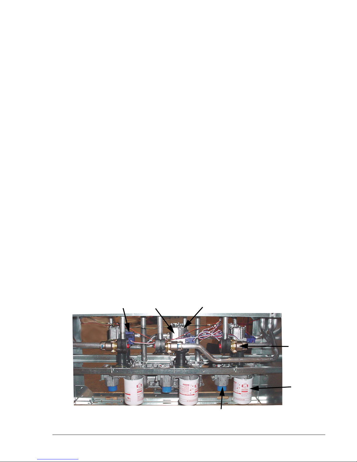
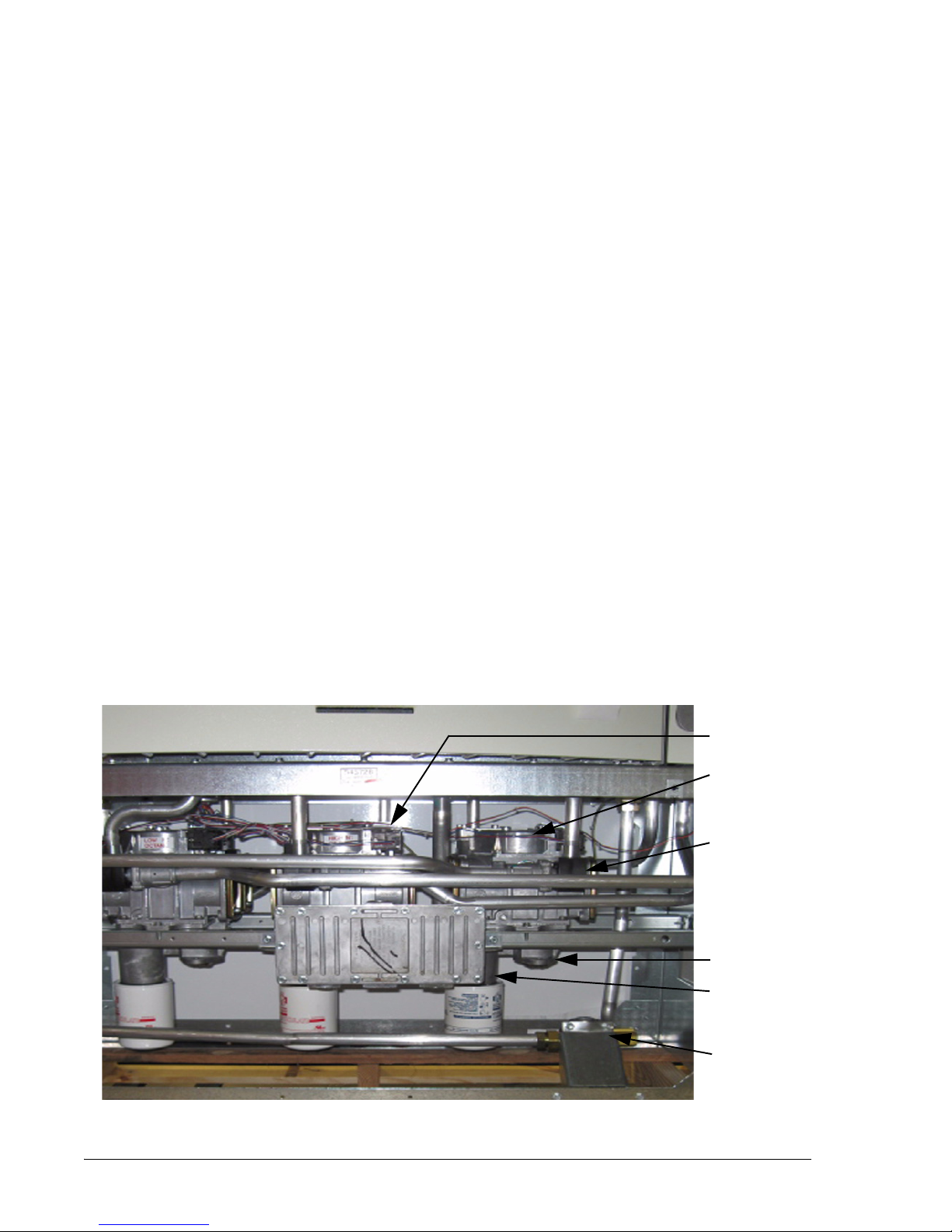
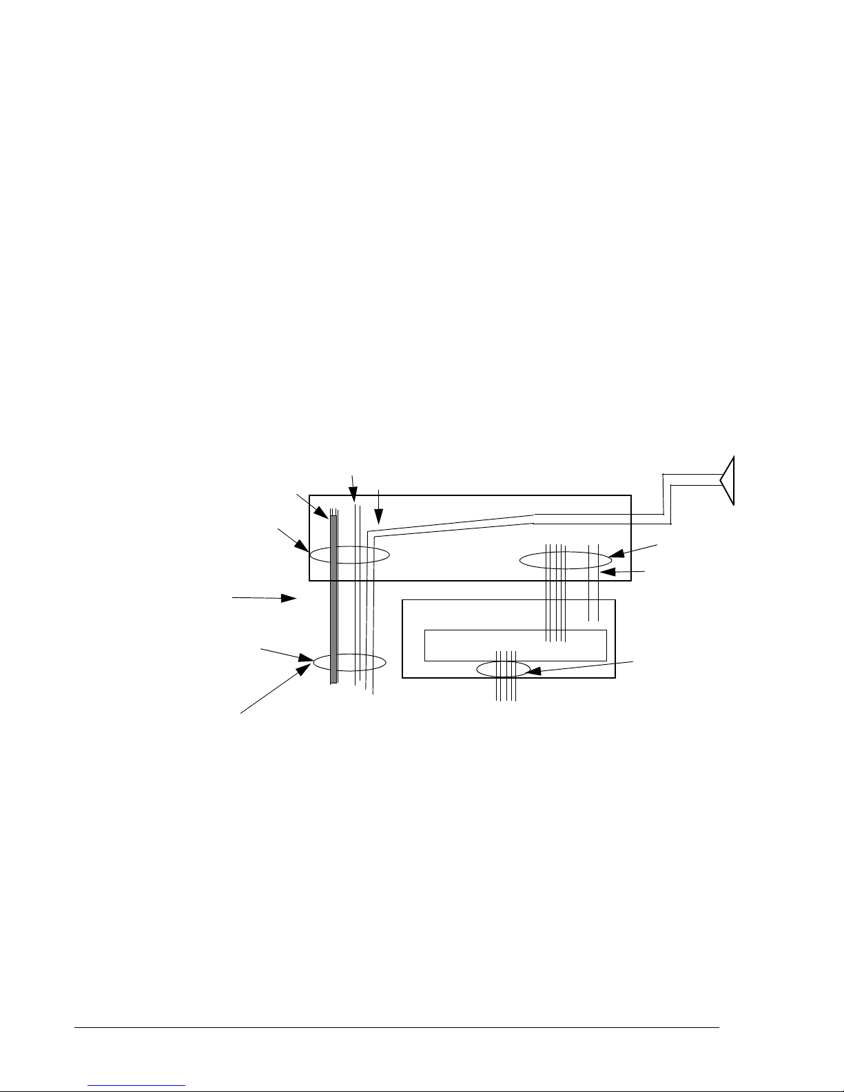
junction box. On those models, the primary conduit location is moved from 1.37 to 2.37 inches off the center line towards the front of the dispenser. Components in a typical Xflo dispenser are shown in Figure 1-1.
E85 Ovation models have the letter E at the very beginning of the model number and use the Xflo meter
assembly. In addition to the noted change above for Xflo models, internal parts such as the Xflo meter, product tubes, and outlet castings, as well as external parts, such as pipes, pipe nipples, hoses, nozzles, breakaways and swivels that come into contact with the Ethanol fuel must be Ethanol compatible; they must be
either nickel-plated or stainless steel. Pipe nipples at the meter inlets need to be made of stainless steel.
Replacement filters should be 1 micron. The recommended filter for Wayne Ethanol dispensers is Cim-Tek's
Bio-Tek, 1 Micron filter. Standard gasoline dispensers commonly use filters rated at 10 microns.
™ meter assembly with the XWIP. Models with the new Xflo
The iGEM computer runs on software that can be downloaded by a laptop. Dispenser models with the Xflo
meter and XWIP use iGEM rev 46 or later pump software; servTerm version 5.4.2 or later is required for
servicing (loading the computer software or dispenser configuration template), however, this is not required
for installation/startup of the dispenser. If it becomes necessary to reload pump software, always use the latest version. Note: The XWIP case is blue and the iMeter WIP case is black; they are not interchangeable.
Computer function settings that are necessary for Ovation dispenser startup and operation, such as prices,
blending ratios, fueling point number, etc., are included in this manual. If additional information on function
settings and statistics is required, refer to the Ovation Dispenser Service manual, part number 920525-002.
Any questions concerning installation and operation of the dispenser that are not covered in this manual
should be referred to Wayne Technical Support (1-800-926-3737).
XWIP
Pulser
Xflo Meter Dome
Check Valves underneath
Cover Plates
Proportional
Valve and Coil
Figure 1-1 Location of Components in Lower Section. MGD, three Xflo Meters, side 2.
November 2008 Part No. 920559 Rev H
Filter
Product Inlet
1
Page 8

1.2 Local, State, and Federal Codes
All tanks (both underground and above ground), piping and fittings, foot valves, leak detectors, corrosion protection devices, wiring, venting systems, etc., must be installed in accordance with the
manufacturer’s instructions and in compliance with local and regional building codes and requirements pertaining to service stations (or other locations where the dispenser may be installed).
These requirements may include references to the National Electrical Code (NFPA 70), Automotive
and Marine Service Station Code (NFPA 30A); Flammable and Combustible Liquids Code (NFPA
30); Code of Federal Regulations, Title 40, Section 280 (40 CFR 280); United States Environmental
Protection Agency (U.S. EPA) Technical Regulations of 9-23-88 and U.S. EPA Financial Responsibility Regulations of 10-26-1988.
Where local requirements do not specify applicable codes, Wayne recommends using the codes
listed above. These codes are comprehensive and detailed, often requiring interpretation to cover
unusual situations, and, therefore, the associated handbooks (where applicable) should also be consulted. (The handbooks are also available from the same sources.)
Due to the variety of locations encountered, further information on installation cannot be dealt with
in this document except as the codes relate directly to the installation of the dispenser. Therefore, it
is strongly recommended that a qualified engineer or contractor familiar with local regulations
and practices be consulted before starting installation.
Sources for various codes are listed on the following page.
2
Part No. 920559 Rev H November 2008
Page 9

Pertinent information and codes are available from the following sources:
Association for Composite Tanks (ACT)
North State Street
Suite 720
Chicago, IL 60602
(301) 355-1307 (for information requests)
Fiberglass Petroleum Tank and Pipe Institute
One SeaGate, Suite 1001
Toledo, OH 43604
(419) 247-5412
National Fire Protection Association (NFPA)
One Batterymarch Park
Quincy, MA 02269-9101
(617) 770-3000
Petroleum Equipment Institute (PEI)
Box 2380
Tulsa, OK 74101
(918) 494-9696
Underwriters Laboratories Inc.
333 Pfingsten Road
Northbrook, IL 60062
(312) 272-8800
United States Environmental Protection Agency
Office of Underground Storage Tanks
401 M St., SW (05-400WF)
Washington, DC 20640
(703) 308-8850 (Underground Storage Tanks)
American Petroleum Institute (API)
1220 L Street, N.W.
Washington, DC 20005
(202) 682-8000
National Assoc. Corrosion Engineers
(NACE)
Box 218340
Houston, TX 77218
(713) 492-0535
National Leak Prevention Association
(NLPA)
685 Fields Ertel Road
Cincinnati, OH 45241
(513) 489-9844 or 1-(800) 543-1838
Steel Tank Institute
P. O. Box 4020
Northbrook, IL 60065
(312) 498-1980
Underwriters Laboratories of Canada
7 Crouse Road
Scarsborough, Ontario, Canada N1R3A9
(416) 757-3611
Western Fire Chiefs Association
5360 South Workman Mill Road
Whittier, CA 90601
(213) 699-0541
U. S. Department of Labor,
Occupational Safety and Health Administration (OSHA)
Washington, DC 20402
• Call OSHA at (202) 523-8148 to determine specific needs; OSHA rules
are covered by Title 29 of the Code of Federal Regulations (29 CFR.)
• Order OSHA publications from:
Government Printing Office (GPO)
Washington, DC 22304
(202) 783-3238
NOTE: Other regulatory codes may apply. Consult your local and regional code requirements to
determine which codes are applicable for your location.
November 2008 Part No. 920559 Rev H
3
Page 10

1.3 SAFETY PRECAUTIONS
NFPA 30A states that:
“When maintenance to Class I dispensing devices becomes necessary and such maintenance may
allow the accidental release or ignition of liquid, the following precautions shall be taken before
such maintenance is begun:
• Only persons knowledgeable in performing the required maintenance shall perform the work.
• All electrical power to the dispensing device and pump serving the dispenser shall be shut off at
the main electrical disconnect panel.
• The emergency shut-off valve at the dispenser, if installed, shall be closed.
• All vehicle traffic and unauthorized persons shall be prevented from coming within 20 ft.(6 m)
of the dispensing device.
WARNING
Electric shock hazard! More than one disconnect switch may be required to de-energize the
dispenser for maintenance and servicing. Use a voltmeter to make sure ALL circuits in the
dispenser are de-energized. Failure to do so may result in serious injury.
1
”
Lockout/Tagout requirements of the U. S. Dept. of Labor, Occupational Safety and Health Administration (OSHA) may also apply. Refer to Title 29, Part 1910 of the Code of Federal Regulations
(29CFR1910), Control of Hazardous Energy Source (Lockout/Tagout).
NOTE: To prevent damage to components located in the hydraulic cabinet, dispenser doors should be
in place during rainy and/or icy weather conditions. Also, check the nozzle boot flipper for
freedom of movement. If ice has formed on the flipper, it should be cleared to prevent
unnecessary damage.
1. Reprinted with permission from NFPA 30A-90, Automotive and Marine Service Station Codes, Copyright
©1990, National Fire Protection Association, Quincy MA 02269. This reprinted material is not the complete
and official position of the National Fire Protection Association on the referenced subject, which is represented only by the standard in its entirety.
4
Part No. 920559 Rev H November 2008
Page 11
2 INSTALLATION
2.1 Inspect the Equipment
Examine the shipment immediately upon arrival to make certain there has been no damage or loss in
transit. Make sure that all the component parts, including keys and optional equipment (if any), are
accounted for. Check and save the Packing Slip, Bill of Lading, Invoice, and all other documents
included in the shipment. Damaged or lost equipment must be reported to the carrier. Any damage or
loss that may occur in transit is not covered under the Wayne/Dresser Warranty.
2.2 Island Construction, Dispenser Anchoring, and Piping
Product lines must avoid the creation of vapor in the lines and deliver a minimum pressure of 25 psi at
the dispenser inlet when all dispensers at the station dispensing the same product are operating.
A concrete foundation must be provided for the dispenser. Do not pour concrete around product lines or
electrical conduit risers.
Anchor bolts must be installed in the island to allow the dispenser to be bolted down in accordance with
NFPA requirements. The base of the dispenser contains six bolt hole slots (5/8 inch by 2 inch) for
anchoring the dispenser to the island. Use of all anchoring locations is re-commended. Position
the anchor bolts in accordance with the dimensions shown on the Installation Instruction drawing for the
dispenser model. These drawings are located in Appendix B.
Vertical supply risers and electrical conduits must be located per the Installation Instruction for the
appropriate model. Proper height must be maintained to avoid undue stress on the dispenser.
For E85 Ovation models, product piping, pipe nipples, etc., containing Ethanol fuel must be Ethanol
compatible. See the information in Section 1.1 on page 1.
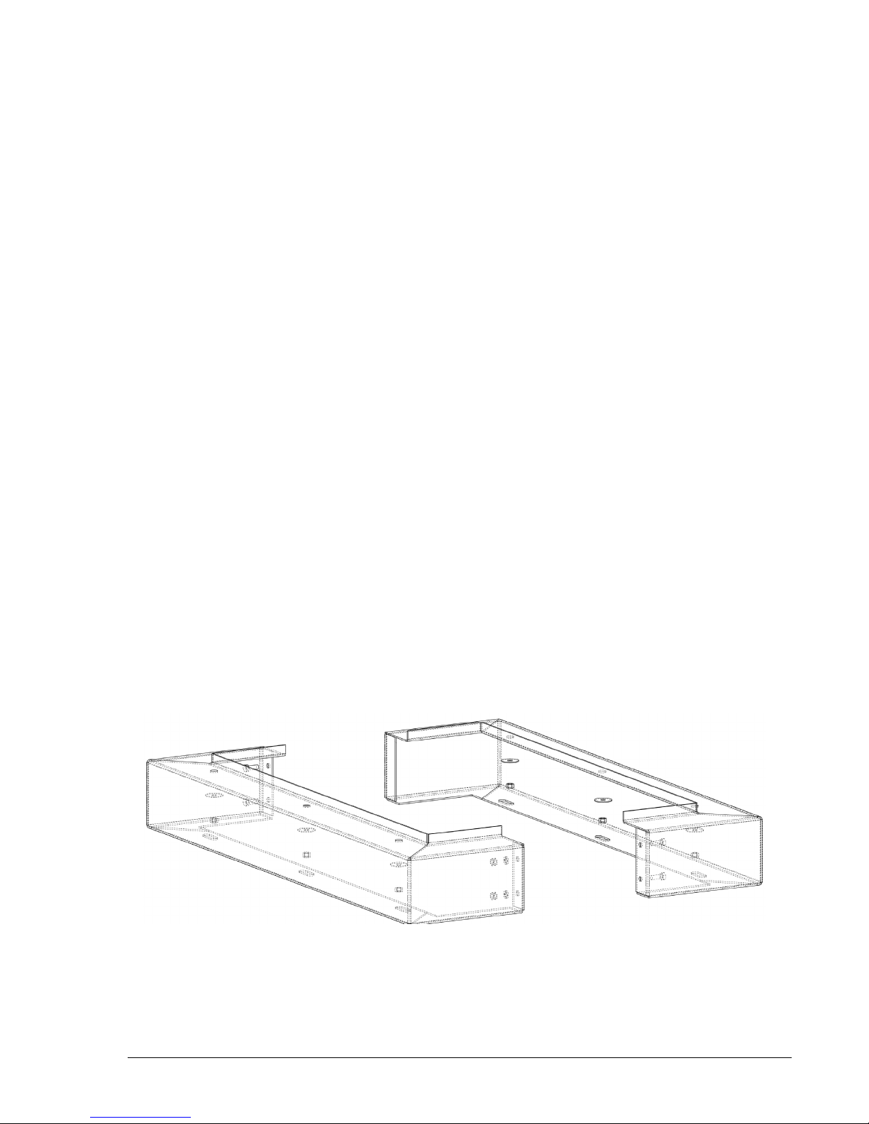
For convenience, a 6” high pedestal is available to install under the dispenser base at locations where
there are no islands. The pedestal, shown in Figure 2-1, can be ordered separately. See the complete
assembly drawing 888813 in Appendix B.
Figure 2-1 Pedestal. See Note under the shear valve drawing on the following page.
November 2008 Part No. 920559 Rev H
5
Page 12
2.3 Emergency Shut-off (Shear) Valves
WARNING
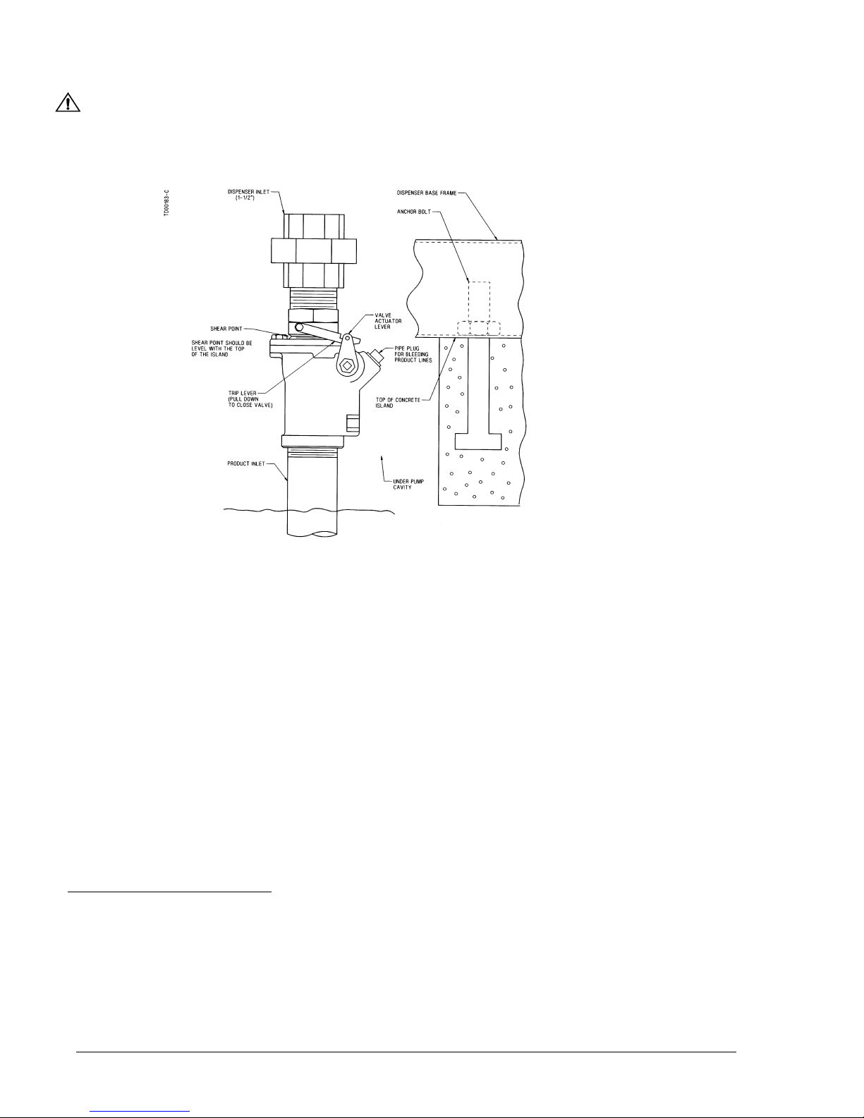
For remote dispensers, a Listed1, rigidly anchored emergency shut-off valve must be installed, in accordance with the manufacturer’s instructions, in each supply line at the base of each dispenser. For a typical emergency valve installation see Figure 2-2. Failure to install the proper emergency shut-off valve will
present a hazardous condition that could result in serious injury.
Figure 2-2 Typical Emergency Valve Installation. The Emergency valve is designed to close the product line due
to shock or fire. The shear section, shown above, functions if the dispenser is knocked out of position.
NOTE: The shear valve must always be at the ground plane. The pedestal shown on the previous page, is considered an extension of the dispenser, not the island.
Note: Wayne does not supply the meter inlet pipe nipple or the union shown above.
2.4 Vapor Return Piping
NFPA 30A Section 4-3-72 states that a vapor return pipe inside the dispenser housing shall have a shear section or flexible connector so that the liquid emergency shut-off valve will function properly. Wayne’s vapor
connections are secured to the chassis allowing for the use of a shear section.
Wayne dispensers provide 1" NPT pipe connections at the base of the dispenser for vapor return connections.
(See the installation foot print for location in Appendix B.) A minimum 1" riser at each dispenser is connected to a minimum 2" return piping to the underground tank. If more than six (6) fueling points are connected, then underground piping must be a minimum of 3". All lines should be sloped at a minimum of 1/8”
per foot (1/4” per foot preferred) from the dispenser to the tank to avoid liquid traps. Note: There is no vapor
recovery for the Ethanol product on E85 Ovation dispensers.
1. “Listed” means published on a list by a nationally recognized testing laboratory (NRTL) which is responsible for product evaluation and is acceptable to the authority having jurisdiction. Underwriters Laboratories, Inc. is one example
of a Nationally Recognized Testing Laboratory. For more information on NRTL’s, see Title 29, Parts 1907 and 1910
of the Code of Federal Regulations, Safety Testing or Certification of Certain Workplace Equipment and Materials.
2. Reprinted with permission from NFPA 30A-90, Automotive and Marine Service Stations Codes, Copyright 1990,
National Fire Protection Association, Quincy MA 02269. This material is not the complete and official position of the
National Fire Protection Association on the referenced subject, which is represented only by the standard in its
entirety.
6
Part No. 920559 Rev H November 2008
Page 13
2.5 Lifting and Installing the Dispenser
Remove the shipping carton from the dispenser and, if the dispenser is equipped with an optional valance, survey the site to determine if it should be installed before or after the dispenser is set on the
island. Wayne recommends installing the valance after the dispenser is installed, if practical, to protect it
from installation damage. See the Valance Module drawing in the back of this manual.
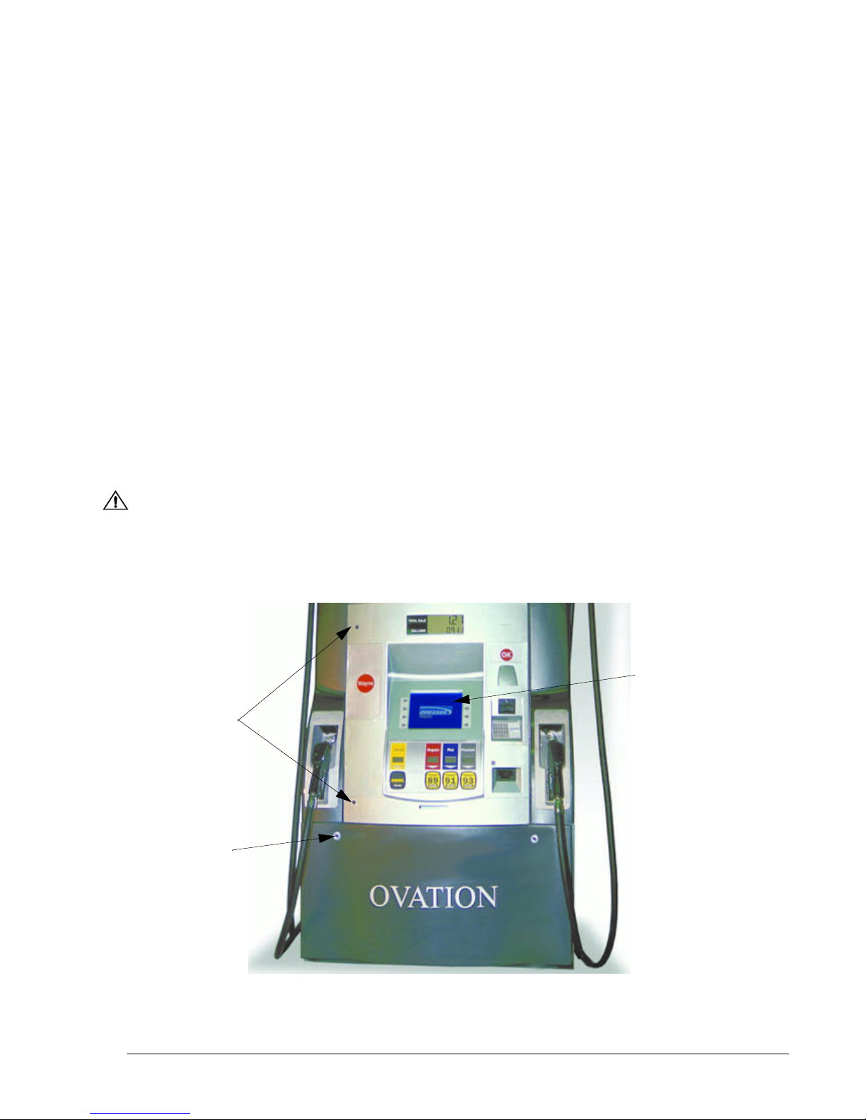
Use door key (p/n 1-202022) to unlock and then remove the lower doors, see Figure 2-3 for location.
Install (2) eye-bolts in the dispenser top castings and lift the dispenser onto the island as per Lifting
Instructions drawing 888514-001 in Appendix B. When handling Ovation dispensers, lift only as per the
Lifting Instructions drawing contained in this manual. Do not lift by the electronic enclosure, nozzle
boot, or any external panels.
Bolt the dispenser into place (Section 2.2), remove the shipping discs from the meter inlets and connect
the product piping per the appropriate Installation Instruction drawing in Appendix B. When installing a
blending dispenser, make sure the Lo and Hi product inlets (and, if applicable, the single product inlet)
are correctly located.
To ensure tight, leak-proof connections when making piping connections, wash all cutting oils off the
threads and use a UL-classified pipe joint sealing compound, rated for use with petroleum-based products.
WARNING
Explosive or flammable vapors may accumulate within the dispenser housing. All piping connections in the final installation must be accurately fitted and all threaded joints tightly made up with a
Listed gasoline-resistant pipe joint compound. Put the compound on male threads only, being
careful not to get excess inside the pipe or fittings. Failure to perform the above will present a hazardous condition that could result in serious injury.
VGA
Screen
Upper Door
Locks
Lower Door
Locks (2)
Option
Figure 2-3 DOOR LOCK LOCATIONS. One door key fits upper and lower door locks.
November 2008 Part No. 920559 Rev H
Optional VGA display screen shown.
7
Page 14
2.6 Electrical Wiring
2.6.1 General
Wayne recommends employing a qualified electrician for all wiring. A hazardous liquid is being handled, so it is
important to ensure that all wiring is in accordance with the National Electrical Code (NFPA 70) as well as all
federal, state and local regulations. Note: U.L. requires that all electrical connections to the dispenser be made
with threaded, rigid conduit and properly sealed conductors. Note: All dispensers and electrical connection
boxes must be grounded per NFPA 70.
2.6.2 Dispenser to Wayne Control System Interconnection
Dispenser installation wiring diagrams are provided in Appendix B. The system interconnection wiring diagrams
supplied are for reference purposes. Use these diagrams along with the wiring diagrams supplied with the control
system for laying out the system wiring requirements for a new site or when making changes to an existing one.
Two da t a wires to the Data Distribution Cabinet are required for the Wayne control system console operation.
Two da t a wires to the Site Controller Cabinet are required for dispenser card processing CAT operation.
Two da t a wires to the Site Controller Cabinet are required for Wayne TRAC operation.
One ethernet cable (gas and oil resistant) is required for dispensers equipped with the IDPOS or iX CAT option
from the switch in the dispenser to the switch in the building, see Section 2.6.6, Figure 2-5 and Figure 2-6. A UL
AWM Ethernet cable, Category 5 or higher, rated at least 300 V, 60 degrees C with a gasoline and oil resistant
jacket may be used. The conduit in the dispenser must be potted at the end of the installation.
Optional equipment wires, see Section 2.6.6.
NOTE: When data wires are installed, only the two data wires from the Data Distribution Cabinet used for pump control
are to be terminated at the dispenser’s terminal strip. The additional data wires should not be physically
connected to the data terminals on the dispenser’s terminal strip. Instead they should be properly terminated
individually using wire nuts.
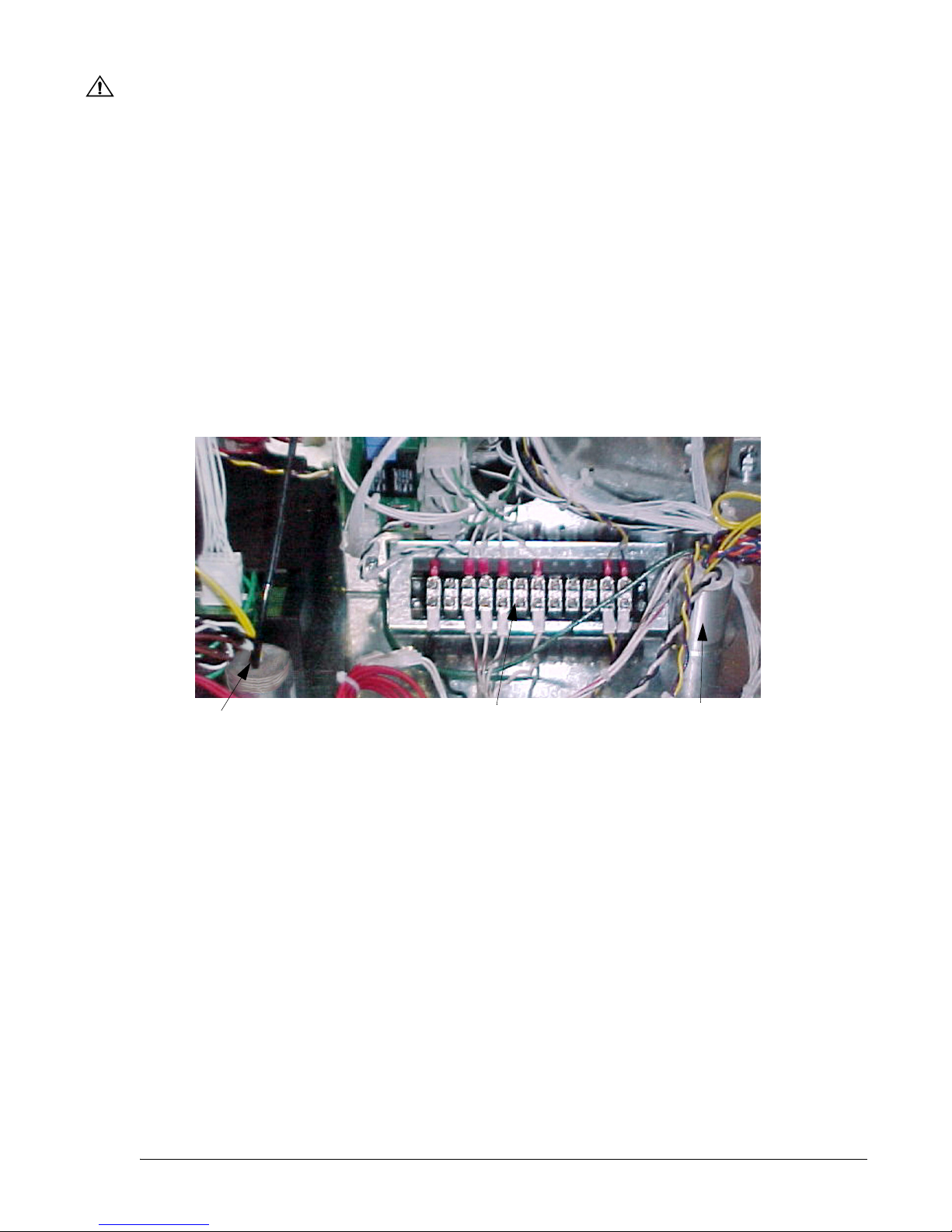
Figure 2-4 shows the location of dispenser components that may need to be accessed during installation. If the
dispenser is not equipped with a junction box in the hydraulic cabinet, field wiring will terminate at the terminal
strip inside the electronic enclosure as shown in Figure 2-5 and the conduit fittings shown will be potted in the
field.
E-M TOTALIZERS
WIP PULSER
CHECK VALVES
(under Valve Plates
in iMeter Dome)
PROPORTIONAL
/
VALVE
VALVE COIL
JUNCTION BOX
PRODUCT INLET
FILETR/STRAINER
CASTING
Figure 2-4 Location of Components in Lower Section (iMeter model shown). Side 1.
See Appendix B for new footprint drawings with the smaller junction box (above) effective in November 2008.
8
Part No. 920559 Rev H November 2008
VAPOR
RECOVERY
OUTLET
Page 15
WARNING
Electric Shock Hazard! No connections (including neutral) may be shared between groups of dispensers.
A separate Control Power Circuit Breaker must be provided for each group. Failure to do so may result in
serious injury.
2.6.3 Field Wiring for Dispensers Without a Junction Box
All field wiring must enter the Electronic Head via potted conduit/conduit fittings. When a dispenser
does not contain a junction box, the conduits must be potted in the field during dispenser installation.
Note: This also applies to the secondary conduit containing the Ethernet cable and the intercom call button/
speaker wires even if the dispenser does have a junction box since these wires do not connect in the junction
box.
1. Install (2) 3/4” field conduits from the UL approved seal-offs at the base of the dispenser to the conduit at
the vapor barrier as identified in Figure 2-5. One conduit will contain, as applicable, the Ethernet cable
and the intercom (call button and speaker) wires (low voltage - Class 2 circuits). The other conduit will
contain the pump power, relay selects, valance lighting and data wires (Power - Class 1 circuits).
Potted conduit for Ethernet and
Intercom Call Button/speaker wires only.
,
Note: With or without j-box,
this conduit now goes directly to the
seal offs under the dispenser to allow
for a straight run of Ethernet cable
from building switch to dispenser switch.
Terminal Block
used when junction box
is not installed.
MGD Wiring Shown.
Potted Fitting contains Pump Power,
Data, Relay Selects, Valance lighting
Note: Main potted fitting contains
intercom speaker wires (Brown pair)
These must run in separate underground
conduit along with the call button wires.
See optional equipment section.
Figure 2-5 Terminal Block Inside Electronic Enclosure. Field wiring connects to this terminal block when
the junction box shown in Figure 2-4 is not installed.
2. Clean conduit threads before connecting.
3. Pull continuous uninterrupted lengths of wires from the station electrical panels and control boxes to the
dispenser electronic head. Allow an extra 18” lengths past the vapor barrier fitting for terminating,
separating, potting and connecting to the terminal block. If installing iX CAT or IDPOS dispensers, allow
an extra 3 ft. of Ethernet cable past the top of the conduit in the vapor barrier.
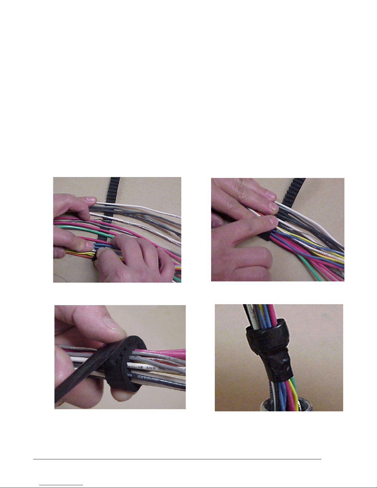
4. From each conduit, separate the wires using 3-201623 Wire Separator Gasket. See Photo 1.
5. Roll separator gasket and wires into a cylinder and secure with electrical tape. Photo 2 and Photo 3.
6. Pull separator gasket and wires back through the conduit fitting (Photo 4) forming a dam in the conduit,
with the top of the separator down in the conduit past the dimple in the conduit.
November 2008 Part No. 920559 Rev H
9
Page 16
2.6 Electrical Wiring, continued
7. Trim wires to appropriate length, terminate ends and connect to the terminal block as per Wiring Diagram
drawing 888445-001 located in the Appendix B of this manual. Note: Field wires are to be connected to
the lower terminals on the block.
8. Prepare the potting compound by pouring 4 oz. Rockite into an eight oz. paper cup.
9. Add 1-1/2 oz. of water.
10. Stir one to two minutes until reaching a consistency similar to pancake batter.
11. Pour mix into fitting and fill to within 1/8” of top of fitting (or top of conduit if the Ethernet conduit).
12. Close the service door.
13. Let fitting set for 12 hours. The wires must not be moved during this time.
Photo 1. Photo 2.
Photo 3. Photo 4.
10
Part No. 920559 Rev H November 2008
Page 17

2.6.4 Full Service (Stand-Alone) Dispenser Wiring
For full service operation, make electrical connections as shown on the Installation Wiring Diagram in
Appendix B. The electrical connections illustrated are typical when additional like model dispensers are
used.
Data wires shown on the wiring diagram are for connecting the dispenser to the Data Distribution Cabinet and the Site Controller Cabinet in a Wayne Control System. These data wires are not required for the
full service (stand-alone) dispenser. However, the six optional data wires and cable, whichever are
applicable, as described in Section 2.6.2, should be run at initial installation if a control system or
optional equipment is being installed or may be installed in the future.
Remote dispensers require a relay to control the submersible pump motor. These relays are available as
an option with the Wayne control system. If the dispenser is not connected to a Wayne control system, a
UL Listed magnetic motor controller assembly, constructed with Potter and Brumfield Relay No.
PRD7AYO (120) or equivalent, shall be used.
A maximum of 12 dispensers (24 fueling points) may be connected to a single PRD7AYO (120) relay;
other relays may have different limitations. All dispensers operating the same pump control relay must
be connected to the same circuit breaker; this may require multiple control relays for a submersible
pump.
Ensure that the submersible pump receives its power from its own separate circuit breaker as illustrated
in the Typical Site Wiring Diagram in Appendix B.
2.6.5 Multiple Dispenser Wiring
A primary requirement in dispenser installation wiring is to provide a means for disconnecting all power
connections, including the neutral, to the dispensers for safe shutdown and servicing of the units. Each
dispenser could be provided with a separate control Power Circuit Breaker. If this is not desirable or
practical, several dispensers can be grouped together and tied to the same Control Power Circuit Breaker
as illustrated in the Typical Site Wiring Diagram in Appendix B. A group of dispensers would then consist of all the dispensers and associated Submersible Pump Control Relay coils supplied by the same
Control Power Circuit Breaker.
When more than one dispenser within the group activates the same submersible pump, the Relay Select
lines may be commoned at the Submersible Pump Control Relay Coil terminal up to a maximum of 12
connections (24 fueling points). Where more than 12 connections activate the same submersible pump,
additional relays should be used and the contacts paralleled as illustrated in the Typical Site Wiring
Diagram.
In larger installations, dispensers can be separated into multiple groups.
November 2008 Part No. 920559 Rev H
11
Page 18
2.6.6 Optional Equipment
Dispensers contain an extra pair of data wires in the junction box for Wayne TRAC as shown in
Figure 2-6 below. These wires are also identified in the installation wiring diagram in Appendix B.
Dispensers with the letter I in the model number will have an intercom call button.
Brown wires are speaker connections. Yellow wires are call button connections see Figure 2-6. Both
circuits are low voltage NEC Class 2 only.
Dispensers with a 3 or 6 in the main body of the model number indicates the dispensers are equipped
with iX CAT board option, VGA or QVGA, respectively. And, dispensers with the letter “L” in the 1st
suffix of the model number indicates iX Secure Keypad. All of these dispensers will require an unin-
terrupted run of Ethernet cable from the switch in the building to the switch in the dispenser electronic head. These dispensers will need a secondary underground conduit for this cable and other
NEC Class 2 wiring as shown below. From the factory, these dispensers will contain a short section of
conduit that can be used for making the connection to the secondary conduit seal off under the dispenser.
NOTE: The field Ethernet cable and Intercom (Call Button and Speaker) wires (NEC Class 2) must be
installed via a separate underground conduit to the dispenser. The intercom/speaker and call button
wires should be terminated with wire nuts in the electronics head.
Call Button
Ethernet Cable for
iX CAT or
(NEC Class 2)
Underground Conduit
for Ethernet cable and
Intercom (call button
and speaker) wires only.
Note: This conduit now goes directly to the seal offs
under the dispenser to allow for a straight run of
Ethernet cable from building switch to dispenser switch.
IDPOS option
Secondary Conduit
in Electronic Head
Y
••
Y
Speaker
Junction Box
Electronic Head
Terminal Strip
BN pair
•
•
BU
OR
_
+
•
•
•
(NEC Class 1)
Underground Conduit
for Pump Power,
and Data,
Valance lighting
and relay select wires.
Speaker
Main Conduit in
Electronic Head
Data Wires for
Wayne TRA C
option
Wire Nut (typical)
Figure 2-6 Ethernet, Intercom Call Button and Speaker Wiring. Ethernet and Intercom (Call Button and
Speaker) wiring must run in a separate underground conduit to the dispenser.
2.6.7 Veeder-Root Vapor Flow Meter
Refer to the installation procedures in the Veeder-Root Manual No. 577013-796 Rev E (page 6, instruction steps 11 and 12) supplied with dispensers equipped with the Veeder-Root option.
2.6.8 Non-Dispenser Equipment
Do not run wiring for any non-dispenser equipment, in the same conduit as the dispenser wiring; this
wiring must be run in a separate conduit.
12
Part No. 920559 Rev H November 2008
Page 19

2.7 Hose and Hose Retractor
Hose assemblies should be U.L. Listed and installed in accordance with the manufacturer’s instructions. To
ensure a proper joint, wash all cutting oil off the threads and use a U.L. classified gasoline-resistant pipe joint
sealing compound. Place the compound on male threads only; be careful not to get any excess compound
inside fittings. Install the fixed end of the hose to the dispenser outlet; secure according to the instructions of
the sealing compound and hose manufacturers. Install the swivel end of the hose or other swivels to the nozzle according to the manufacturer’s instructions.
Exception: Do not use the sealant on balanced or inverted hoses used with vapor recovery.
NFPA code requires a Listed emergency breakaway device, designed to retain liquid on both sides of the
breakaway point, must be installed on each hose dispensing Class I liquids; these devices must be installed
and maintained per the manufacturer’s instructions. Refer to your state and local codes for breakaway device
requirements that apply to your installation.
On E85 Ovation dispensers, all hoses, nozzles, breakaways, etc., containing the Ethanol fuel must be Ethanol
compatible. See the information in Section 1.1 on page 1.
On Wayne vapor recovery dispensers all hoses, nozzles, and breakaways, etc., must be CARB certified.
Hose Retractor: Caution!: On dispensers equipped with the Hose Retractor option, the hose clamp must
be mounted upstream of the breakaway device to avoid damage to the dispenser in the event of a drive-off.
The combined hose, breakaway, and whip maximum lengths are listed below.
Crossover Type
1 Hose per Side
Wayne Vac 14’ 0’’
Non-Vapor 3/4” 10’ 0’’ 10’ 0’’
Non-Vapor 5/8” 14’ 0’’ 14’ 0’’
WARNING
Use only Listed hoses and nozzles. Continuity must be present between the dispenser outlet and nozzle
spout to prevent static discharge while fueling. Continuity must be checked for each outlet/hose assembly to insure that the nozzle is grounded. Failure to do so may result in a hazardous condition that could
cause serious injury.
Loopback Type
1 Hose per Side
Loopback Type
2 Hose per Side
2.8 Bleeding Product Lines (Remote Dispensers)
NOTE: To avoid severe damage to the dispenser, all air and air pockets must be bled from the product trunk
lines before attempting to dispense product.
Step 1 Make sure the power to the appropriate submersible pump is OFF.
Step 2 To bleed air from a trunk line, remove the pipe plug from the safety impact valve on the dispenser
farthest from the storage tank. For pipe plug location see Figure 2-2 earlier in this section.
Step 3 Attach a flexible hose to the pipe plug opening in the safety impact valve. Energize the appropriate
submersible pump and allow the air to bleed out of the trunk line into a test can until product flows
into the test can. De-energize the submersible pump and replace the pipe plug. Repeat the procedure
for each product and each trunk line.
November 2008 Part No. 920559 Rev H
13
Page 20

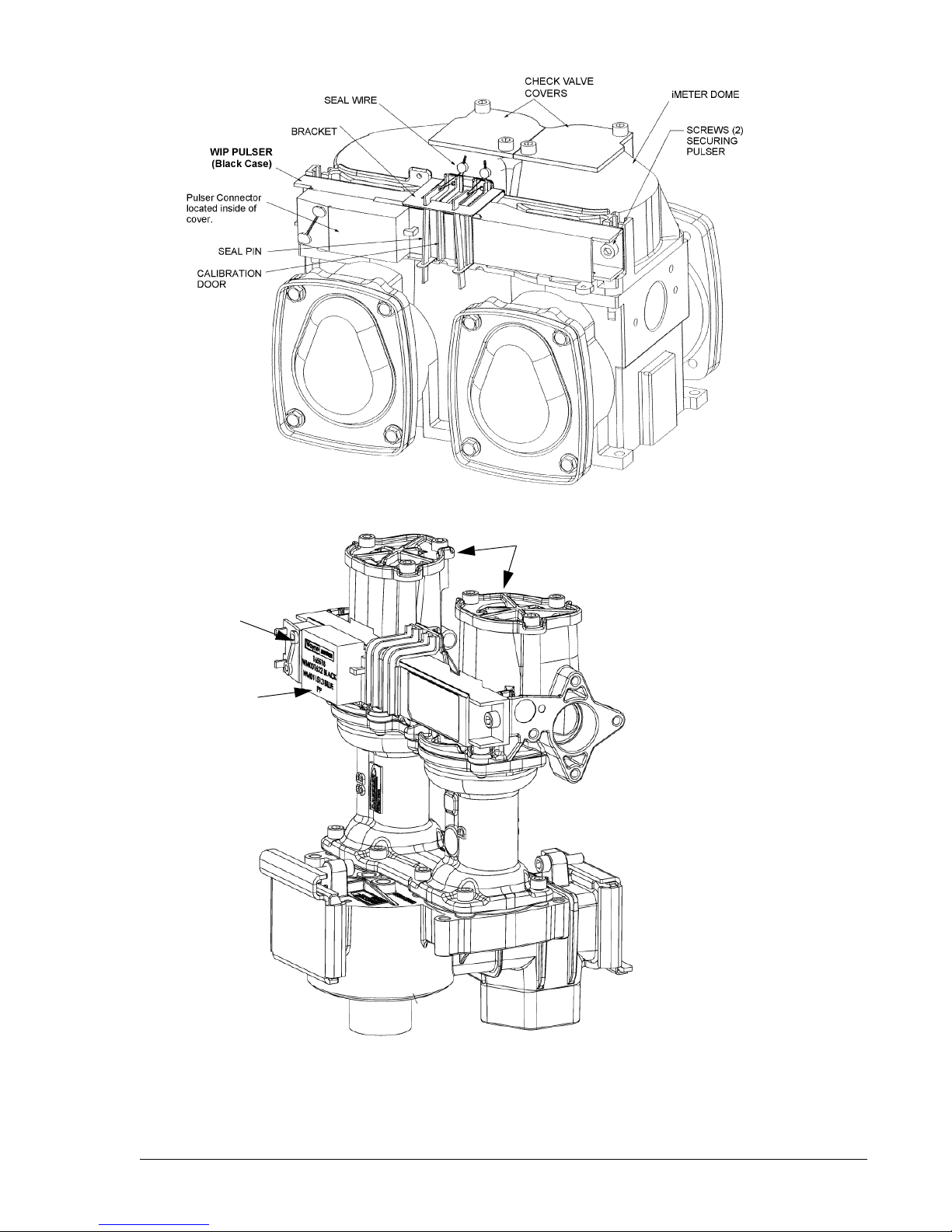
2.9 iMeter or Xflo™ Meter Calibration Procedure
Sufficient product must be run through each meter to thoroughly flush out all air and completely fill the system
prior to the calibration process.
Each meter assembly contains two meters. The WIP pulser (or XWIP for Xflo meter) contains two sets of sensors, one set for each meter. On the front of the pulser, there are two calibration doors, one for each meter in
the assembly. The door closest to the front of the dispenser controls calibration of the front meter and the other
door controls calibration of the rear meter.
(only one meter at a time can be calibrated).
assure the correct door is opened during the calibration process.
Dispensers have an operation mode setting that establishes the pulser’s calibration mode. This is set at the factory in the dispenser template (Read Only function F16). The imeter and the Xflow meter are calibrated using
the same procedure as shown below.
Verification Accuracy:
1. Dispense some product into the test measure to wet the container and then drain the container thoroughly, 10 seconds or more.
2. Dispense product into test measure until exactly 5 gallons (20 liters) are shown on dispenser display.
See Note 1.
3. Compare reading on site glass of test measure to dispenser display. Volume in test measure should be
within +/- 3 cu. in. (+/- 50 ml). See Note 2.
Only one door may be opened at one time during meter calibration
It is important to verify the product grade for each assembly to
4. If values are out of range, calibrate as described below.
Calibration:
1. Identify calibration door for meter in need of calibration.
2. Remove seal wire and pin to allow access to door.
3. Dispense some product into the test measure to wet the container and then drain the container thoroughly, 10 seconds or more.
4. Open calibration door of meter to be calibrated. (Only one door can be opened at a time during the calibration process).
5. Dispense exactly 5 gallons (20 liters) into the test measure exactly to the “0” mark on the sight glass
(read the bottom of the meniscus).
6. Close the calibration door. (This now redefines the calibration factor in the pulser).
7. Empty the test measure (drain completely, 10 seconds or more) and verify accuracy as described above.
8. Seal calibration door.
Note 1: In the Liter mode, in addition to 20 liters, a 10 liter or 5 liter test measure may be used if required
by the application. However, you should check with your jurisdiction on Weights & Measures tolerance
requirements.
Note 2: For the U.S. and Canada, acceptance tolerance of ±3 cu.in. for a 5 gallon measurement and ± 50
ml for a 20 liter measurement is only required for newly installed, newly placed in service devices for 30
days. After 30 days, the tolerance is increased to ±6 cu.in. for 5 gallons and ±100 ml for 20 liters.
14
Part No. 920559 Rev H November 2008
Page 21
Dispenser
Front
(Side 1)
iMeter
(Side 2)
Meter A
Meter B
(Side 2)
Pulser Connector
located inside of
cover
XWIP
Pulser
(Blue Case)
Check Valve
Covers
Xflo Meter
Meter B
Meter A
Dispenser
Front
(Side 1)
Figure 2-7 Meter Assemblies. The WIP and the XWIP are physically the same size, but have a different
Note:If for any reason the pulser is replaced, be sure the replacement pulser’s tabs snap
into place in the meter slots before tightening the two screws securing the pulser.
November 2008 Part No. 920559 Rev H
colored case because they are not functionally interchangeable.
15
Page 22

2.10 Balance Vapor Recovery System Installation Requirements
2.10.1 Dynamic Back Pressure Testing
At initial installation, balance vapor recovery dispensers should have a dynamic back pressure test
performed at each nozzle to ensure there are no blockages in the vapor recovery system.
The dispenser should be connected to the underground and the hanging hardware (hoses, nozzles,
breakaways, etc.) should be installed.
The following test methods or equivalent methods can be used:
“ST-27 Gasoline Dispenser Facility Back Pressure.” Available from the California Bay Air
Management District via the Internet at http://www.baaqmd.gov/mop/vol4/v4index.htm
“TP201.4” Determination of Dynamic Pressure Performance of Vapor Recovery Systems of
Dispensing Facilities.” Available from the California Air Resources Board.
Maximum allowable dynamic back pressure for an individual dispenser nozzle using either test procedure is listed below:
60 cu. ft. per hr. <
80 cu. ft. per hr. <
0.35 in. of water
0.62 in. of water
Note: Very low numbers for back pressure results may indicate a leak in the system and it should
be checked.
2.10.2 Back Pressure System Check List
Note: Check test equipment for up-to-date calibration stickers. Normal use of rotameters and
pressure gauges necessitates yearly calibration; calibration is also required if this equipment has
been dropped or mishandled.
1. Check test equipment for leaks prior to use. Pressurize with nitrogen supply (plug nozzle end of
the fill pipe). Adjust nitrogen until 50% on pressure gauge is reached. Close off supply. A pressure decay must not be more than 0.2 in. of water in five minutes.
2. If facility has a vapor pod (condensate pot), drain prior to testing.
3. Open dry break poppets.
4. Completely drain hoses and nozzles prior to test. A pulsating needle indicates fluid in the lines.
Re-drain if necessary.
5. The following information should be included on the field data sheet:
• Facility address and ID
• Pump number and grade ID
• Nozzle make and model
• Back pressure in inches of water
• Nitrogen flow rate
16
Part No. 920559 Rev H November 2008
Page 23
2.10 Balance Vapor Recovery System Installation Requirements, continued
6. If back pressure readings are very low (less than .02 @ 20 CFH; 0.18 @ 60 CFH; 0.4 @ 100 CFH):
1. Check test fixture for tight seal at nozzle entry point.
2. Check bellows and face seal for tears.
3. Check vapor piping for leaks.
7. If back pressure readings are high:
1. Check hoses and nozzle bellows are completely drained.
2. Check dry break is open. (If only allowed to have one dry break open during the test, try all.)
3. Check vapor pod.
4. Check vapor impact valve to be open.
5. Check piping under dispenser. Should be a minimum of 1 inch diameter piping and fitting.
6. Check dispenser back pressure, disconnected from the underground and compare to dispenser base line
data.
7. Check hanging hardware separate from dispenser and compare to balance hardware matrix base line
data.
8. Check outlets, hose, and underground, for suspect blockage problems due to fitting bottomed out or
casting flashing. Flashing is aluminum edges left over when the casting was made. This should be your
last resort to diagnosing high back pressure readings since piping will have to be removed to look
inside the casting for flashing. A large amount of flashing would be required to affect readings.
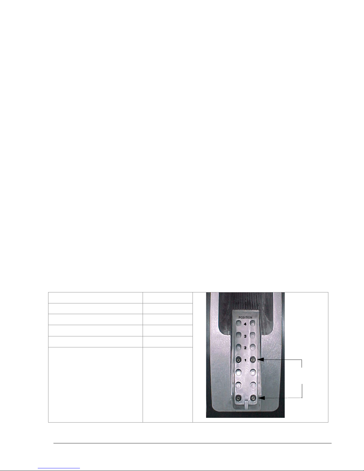
2.10.3 Nozzles Approved for Balance System
The Ovation nozzle boot hook can be adjusted to accommodate different nozzles. Table 2-1 shows the nozzles
approved for use with a balance system and the hook position for each nozzle. Position 1 is the standard position. The hook is in position 1 in the accompanying photo. To change positions, remove the (4) screws shown,
slide the hook down to the new position, and reinstall the (4) screws to secure the hook to the boot.
Table 2-1 Nozzle and Nozzle Hook Position
NOZZLE HOOK POSITION
Emco Wheaton A4005 3
Emco Wheaton A4015 1
OPW 11VF47 4
Husky V Model 5010 and 5020 3
Husky V(short) Model 5110 and 5210 1
1/4-20
Screws (4)
November 2008 Part No. 920559 Rev H
17
Page 24

2.11 Wayne Vac Vapor Recovery System Installation Requirements
2.11.1 Dispenser Vacuum Decay
At initial installation, Wayne Vac vapor recovery dispensers should have a 27” decay test performed on
each point to ensure there are no vapor leaks in the dispenser/hanging hardware - hose, nozzle, breakaway, etc. This test is used to verify the dispenser/hanging hardware integrity so the vapor assist system
will operate at its peak performance.
The test should be performed with the proper hanging hardware installed on the dispenser and the dispenser disconnected from the underground piping.
Connect the test equipment to the discharge of the vapor piping in the dispenser and apply 27” of water
vacuum to the vapor line. Then close off the vapor line and determine if the closed vapor system can
maintain the 27” of water vacuum.
The system should hold the vacuum for one minute. If it does not, apply 10” of water pressure to the system, soaping all connections to find the leak. Use a light soap solution; a heavy soap solution could mask
leaks. If the system piping is tight, check hanging hardware by bagging the nozzles and doing a vacuum
test again, while looking for the bags to deflate. The Wayne vacuum tester, as discussed below, is also
used to test nozzles for leaks.
2.11.2 Wayne Pressure/Vacuum Tester
The Wayne Pressure/Vacuum Tester, part number 1-921168-KIT, is available from Wayne to perform this
test. The Operation manual, part number 920372 included in the kit, explains the various tests that can
performed using both vacuum and pressure.
Additional information on these tests is contained in the Compliance Testing and Preventative Maintenance manual, part number 917947, supplied with each Wayne Vac equipped dispenser.
18
Part No. 920559 Rev H November 2008
Page 25
3START-UP
3.1 Initial Checkout
Before applying power to the dispenser, double-check the wiring to make sure the wires are correctly routed
and terminated. Turn on the dispenser control power circuit breaker and the submersible pump or suction
pump motor circuit breakers. Make sure the dispenser comes on and all lights work. The dispenser displays
will show some numbers, usually the last sale run during factory test.
The dispenser template, which configures the dispenser, has been loaded in the dispenser and tested at the factory. The dispenser will have the necessary data such as unit prices and blend ratios to allow the dispenser to
operate in stand-alone at installation to purge product lines and test operation. At start-up, the procedures in
this section should be performed in sequential order to ensure proper operation before the dispenser is
switched over to control system operation.
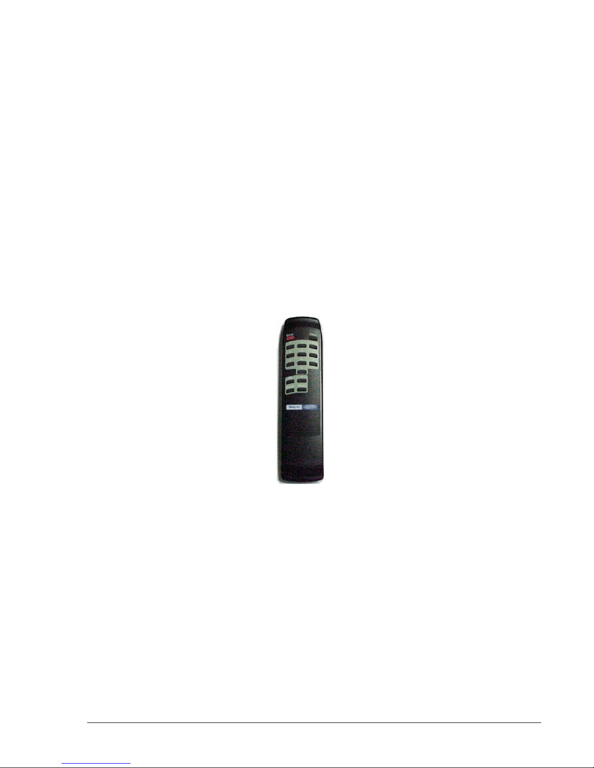
3.2 IR Remote Control
The Infrared Remote (IR) Control shown in Figure 3-1 is similar to a television remote control. It has
16 buttons and, when held close (12-18 inches) to the infrared eye located on the sales display board, is used
to access dispenser functions and statistics. The IR remote, as discussed in the following sections, is used to
set the clock, unit prices, fueling point IDs, blend ratios, and read electronic totalizers.
Figure 3-1 IR Remote Control. Hold remote close to the sales display to set the clock, unit prices,
blend ratios and fueling point ID, read totals, view error codes and other dispenser diagnostic functions.
November 2008 Part No. 920559 Rev H
19
Page 26

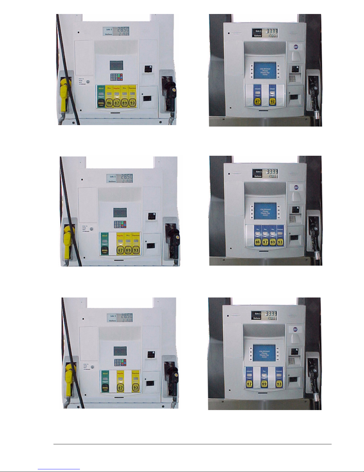
3.3 Logical Nozzle/Hose Positions
The physical number of hoses on one side of the dispenser is not the same as the number of electronic hose
positions on that side. Unit prices and blend ratios are set in electronic hose position or logical nozzle order.
B23/3, B23/4 and B23/5 model Blenders each have 2 hoses per side and 3 inlets, but either 3, 4 or 5 grade
selects/logical nozzles as shown in Figures 3-2 A-C. Logical nozzles are assigned positions 1 through 7,
depending on the dispenser model as shown in Table 3-1.
Three product MGD models have one hose per side and three logical nozzles, which are positions: 1, 2, and
3. For these non-blending models, such as the R13/3, these products are shown as the X, Y, Z products in
Tab l e 3-1.
Logical nozzle positions for the Ovation models listed below are also shown in the examples in
Figures 3-2 and 3-3 on the following pages.
Table 3-1 Hose (Logical Nozzle) Positions Defined by Values of N.
Ovation Model
# begins with
B23/5 Two Hose (1+4)
B23/4 Two Hose (1+3)
B23/3 Two Hose (1+2)
B12/5 Single Hose 5 Grade
B12/4 Single Hose 4 Grade
B12/3 Single Hose 3 Grade
B12/2 Single Hose 2 Grade
R13/3 3 Grade
R22/2 2 Grade
Dispenser
Description
Blender
Blender
Blender
Blender
Blender
Blender
Blender
Non-Blender
Non-Blender
N=7 N=6 N=5 N=4 N=3 N=2 N=1
Lo
Feedstock
Lo
Feedstock
Lo
Feedstock
Lo
Feedstock
Lo
Feedstock
Lo
Feedstock
Lo
Feedstock
Lo-BL Mid-BL Hi-BL Hi
Lo-BL Hi-BL Hi
Lo-BL Hi-BL Hi
Feedstock
BL Hi
Feedstock
Hi
Feedstock
Feedstock
Feedstock
BL Hi
Feedstock
Hi
Feedstock
ZYX
Single
Grade
Single
Grade
Single
Grade
Y X
R11/1 1 Grade
Non-Blender
Model number designations are defined as follows:
B23/5 model, B = Blender, 2 = two hoses per side, 3 = three inlets, 5 = five grade selects.
R13/3 model, R = Regular piped non-blender, 1 = one hose per side, 3 = three inlets, 3 = three grade selects.
20
Part No. 920559 Rev H November 2008
X
Page 27
position
1
positions
6,5,4,3
positions
7,3
Model B23/5220D1 Model B12/2220D3
positions
7,6,5,4
position
1
positions
6,5,4
Model B23/4220D1 Model B12/4220D3
position
1
positions
6,4
positions
7,5,3
Model B23/3220D1 Model B12/3220D3
Figure 3-2 Blending Models.
21
November 2008 Part No. 920559 Rev H
Page 28

position
1
position
1
Model R11/1220D1 Model R22/2220D1
positions
1,2,3
position
2
22
Part No. 920559 Rev H November 2008
Model R13/3220D1
Figure 3-3 Non-blending Models.
Page 29

3.4 Setting the Clock
The time and date is set in function F02 Clock Configuration. The sub-functions F02.00 is the time
HH.MM, F02.01 is the date MM.DD and F02.02 is the year YY.YY.
1. Press ENTER
PA S S 1 (enter password)
2. Press ENTER
PA S S 2 (enter password)
3. Press ENTER. The unit price display will show F— (indicating it needs a function number to proceed)
4. Press 02 to access F02
5. Press ENTER. The unit price display will show F02 (indicating the function has been accessed)
6. Press ENTER to access the sub-functions of F02. The unit price display will show 2.00
3.5 Setting Unit Prices
The procedure below is used to set the dispenser unit prices when operating in stand alone mode or when
communication with the POS system is disabled. When communication with the POS system is enabled,
the system will not allow unit price setting at the dispenser.
The pump computer recognizes code stored in memory that defines a dispenser model and assigns logical
nozzle numbers to the hose positions as discussed in the previous sections. To set unit prices on side 1 and
side 2, functions F03 and F04 are accessed using the remote control interface. Credit prices on side 1 are
set using sub-functions F03.0N while cash prices are set using sub-functions F03.1N, where N is the logical nozzle number. Active values of N are given in Table 3-1. For side 2, the corresponding sub-functions
are F04.0N and F04.1N, respectively.
To set the unit price, the correct sub-function is accessed, the unit price is changed to its new value and the
data is saved. To access the desired sub-function, perform the following steps using the remote control.
Bold type denotes remote control function; italicized type denotes dispenser response.
Accessing the Unit Price Sub-function for Side 1.
1. Press ENTER
PA S S 1 (enter password)
2. Press ENTER
PA S S 2 (enter password)
3. Press ENTER. The unit price display will show F— (indicating it needs a function number to proceed)
4. Press 03 to access F03
5. Press ENTER. The unit price display will show F03 (indicating the function has been accessed)
6. Press ENTER to access the sub-functions of F03. The unit price display will show 3.01
At this point, pressing of NEXT will advance the sub-function to the next sub-function, incrementing the
value of N by (.01). For example, to access F3.02, press NEXT. The unit price display will show 3.02,
press NEXT. The desired sub-function depends on the dispenser type. Table 3-1 shows the values of N
that define the desired sub-functions for the dispenser models shown. Once the desired sub-function is
accessed, the price display will
show “– – – – – –“ and the volume display will show the current value of the unit price. The following procedure must then be followed to set the unit price.
November 2008 Part No. 920559 Rev H
23
Page 30

3.5 Setting Unit Prices, continued
Changing the Value of the Unit Price
Type in the new unit price with at least three digits for three money display digits to be shown after the
decimal point. For example, to set the new unit price to $1.50, type in 1500. Type in 1509 for $1.509
unit price.
1. Press # key. The volume display will show the unit price with the correct number of digits after the
decimal point. Again, for the example above, the volume display will show 1.500.
2. Press NEXT to input the next unit price, and repeat steps 1 and 2. Continue until all the unit prices
are input. Note that while inputting the unit prices, the unit price display continues to show the
sub-function and not the unit price itself.
Save the New Unit Prices as follows:
1. Press ENTER. The price display will show “– – – – – –“, the volume display will be blank and
the unit price display will show the last sub-function accessed.
2. Press 00 (to access F00)
3. Press ENTER. The unit price should now display F00, the price display will show “– – – – – –“
and the volume display will be blank.
4. Press ENTER and the volume display will show a 1.
5. Press UP twice to change the value in the volume display from 1 to 3
6. Press ENTER. The volume display should show a 3.
7. Press ENTER. CHANGE STORED should appear on the display momentarily. The display
should return to normal in a few seconds. When it does, the unit price displays should show the
new prices. If they do not show the desired unit prices, access the appropriate sub-function to
make sure that the unit price data is correct.
24
Part No. 920559 Rev H November 2008
Page 31

3.6 Setting Blend Ratios
The procedure below is used to set the dispenser blend ratios. When enabled, the POS system verifies and
confirms that its blend ratio data corresponds to the manually set blend ratios. The Wayne POS system will
not allow fuel to be dispensed if these numbers do not match.
The pump computer recognizes code stored in memory that defines a dispenser model and assigns logical
nozzle numbers to the hose positions as explained in Section 3.3. Once this is done, the function F18 is
accessed to set the blend ratios, using the remote control interface. The sub-function F18.1N, where N is the
logical nozzle number, is used to set the blend ratios for side 1 and the sub-function F18.2N is used to set
the blend ratios for side 2. Active values of N are given in Table 3-1.
To set the blend ratio, the correct sub-function is accessed, the blend ratio is changed to its new value and
the data is saved. To access the desired sub-function, the following steps must be performed using the
remote control (Bold type denote remote control function and italicized type represents dispenser response):
NOTE: BLEND RATIOS MUST BE SET FOR SIDE 1 AND AGAIN FOR SIDE 2.
To access the Blend Ratio sub-function:
1. Press ENTER
PASS 1 (enter password)
2. Press ENTER
PA SS 2 (enter password)
3. Press ENTER. The unit price display will show F— (indicating that it needs a function number to proceed)
4. Press 18 to access F18
5. Press ENTER. The unit price display will show F18 (indicating that the function has been accessed)
6. Press ENTER to access the sub-functions of F18. The unit price display will show 18.11 (here N=1)
The volume display will indicate the value of the blend ratio corresponding to logical nozzle #1(N=1). If
there is no data for this logical nozzle, the number “101” will be displayed. This applies to all logical nozzles. To access the blend ratio for the next logical nozzle, press NEXT. The unit price display will show
18.12 and the volume display will show whatever the value of the blend ratio is for logical nozzle #2. Suc-
cessive presses of NEXT will advance the unit price display to 18.17, the last logical nozzle. Pressing
NEXT again will advance the unit price display to 18.21
, The “2” in “18.21” indicates Side 2 and the “1”,
logical nozzle #1. The volume display will show the blend ratio assigned to logical nozzle #1 of Side 2.
Changing the Value of the Blend Ratio
1. When the desired logical nozzle is shown on the unit price display, enter the desired value of the blend
ratio by using UP and DOWN keys on the remote control interface or by typing the # sign followed by
the value of the blend ratio, followed by ENTER. For example, to change the value of the blend ratio
from 101 to 89, press the DOWN button until 89 shows up on the price display, then press ENTER, or
type in #89, ENTER.
2. Continue until all the blend ratios are entered for side 1.
3. Repeat for side 2 and save as follows:
November 2008 Part No. 920559 Rev H
25
Page 32

3.6 Blend Ratio Setting, continued
Saving the New Blend Ratio
1. Press ENTER. The price display will show “– – – – – –“, the volume display will be blank and the unit
price display will show the last sub-function accessed.
2. Press 00 (to access F00)
3. Press ENTER. The unit price should now display F00, the price display will show “– – – – – –“
and the volume display will be blank.
4. Press ENTER and the volume display will show a 1.
5. Press UP twice to change the value in the volume display from 1 to 3.
6. Press ENTER. The volume display should show a 3.
7. Press ENTER. CHANGE STORED should appear on the display momentarily. The display should
return to normal in a few seconds. When it does, the unit price displays should show the new prices. If
they do not show the desired unit prices, access the appropriate sub-function to make sure that the unit
price data is correct.
For reference, the following is a 50% blend ratio setting for a single hose blender, Ovation model B12/3 xxxx,
as listed in Table 3-1. Any unused position has to be set to 101 not 0.
Side 1 Side 2
18.11 = 101 18.21 = 101
18.12 = 101 18.22 = 101
18.13 = 100 Super (Hi Feedstock) 18.23 = 100
18.14 = 101 18.24 = 101
18.15 = 50 Plus (Blend BL) 18.25 = 50
18.16 = 101 18.26 = 101
18.17 = 0 Regular(Lo Feedstock) 18.27 = 0
Typically, stations sell the low and high grades at zero and 100 percent ratios and may sell the middle grade
at 35 percent or some other intermediate value between 0 and 100. On the above model, the technician
would need to change only sub-functions 18.15 and 18.25 to the intermediate value.
As a reminder, always get the blend ratios from the station owner to avoid any confusion over which values
to use.
26
Part No. 920559 Rev H November 2008
Page 33

3.7 Setting the Fueling Point ID
The procedure below is used to set the pump fueling point address. The pump FPID should be input and
saved before control is transferred to the POS system.
Functions F05 and F06 are accessed to set the FPID on Side 1 and Side 2, respectively. To set the FPID, the
desired FPID must be input and saved.
Accessing the FPID Function.
1. Press ENTER
PASS 1 (enter password)
2. Press ENTER
PASS 2 (enter password)
3. Press ENTER. The unit price display will show F— (indicating that it needs a function number to proceed)
4. Press 05 to access F05
5. Press ENTER. The unit price display will show F05 indicating the function has been accessed and the
volume display will show the current FPID or a “0” when no FPID has been assigned to that dispenser
side.
6. Input the desired FPID by using the UP and DOWN keys on the remote control interface followed by
ENTER, or by typing the # sign followed by the valve of the FPID followed by ENTER.
7. Repeat the procedure for Side 2.
Saving the New FPID
1. Press ENTER. The price display will show “– – – – – –“, the volume display will be blank and the unit
price display will show the last sub-function accessed.
2. Press 00 (to access F00)
3. Press ENTER. The unit price should now display F00, the price display will show “– – – – – –“and the
volume display will be blank.
4. Press ENTER and the volume display will show a 1.
5. Press UP twice to change the value in the volume display from 1 to 3.
6. Press ENTER
7. The volume display should show a 3.
8. Press ENTER. CHANGE STORED should appear on the display momentarily. The display should return
to normal in a few seconds. When it does, the unit price displays should show the new prices. If they do
not show the desired unit prices, access the appropriate sub-function to make sure that the unit price data
is correct.
8. Repeat the procedure for Side 2.
Note: For models equipped with IDPOS, see configration in Section 4.
November 2008 Part No. 920559 Rev H
27
Page 34

3.8 Authorizing the dispenser
The dispenser must be authorized before it will dispense product.
The dispenser filling mode is set in programming function F01. In stand-alone mode (not connected to a
control system), the dispenser is always authorized, unless the dispenser is equipped with the (optional)
Authorize keyswitch on the bezel. This momentary contact keyswitch can be used for one time
authorizations.
When connected to a control system, the system programming determines authorization.
NOTE: At Startup, the local Authorize switch jumper should be removed as explained in Section 3.10.
3.9 Initial Delivery
To dispense product from a newly installed dispenser, make sure unit prices and blend ratios are set (as previously described) and proceed as follows:
1. Authorize the dispenser.
2. Remove the nozzle, start the reset sequence and observe the reset cycle; make sure all sales display and
unit price display elements operate.
3. Check that when reset is started, the correct submersible pump motor is activated, and at the end of the
display reset (approximately three seconds) the solenoid valve(s) opens (listen for the audible click of
the valve(s).
NOTE: Make sure the product lines are properly bled before dispensing any product through a
remote dispenser. Make sure suction pumps are primed before dispensing any product
through a suction pump.
4. After verifying air is bled properly from each trunk line, slowly dispense product through each dispenser until free of air. Dispense enough product through each hose of each dispenser to ensure the dispenser and the lines are free of air, before checking the meters.
5. For dispensers equipped with Wayne Vac, verify that the correct vacuum pump motor is running when
dispensing product. Verify by checking that air is being drawn through the vapor return hole(s) in each
nozzle spout. Also, see Testing Procedures manual, p/n 917947.
3.10 Disable Stand-alone Operation
Once the dispenser is switched over to the POS control system, standalone operation should not be
required. As an extra security measure, the jumper that enables stand-alone operation should be removed.
The jumper is located on the unit price display board as shown in Appendix C of this manual.
1. Access dispenser Filling Mode function F01 and set sub-function to 1.01 for serial mode.
2. Open the service door.
3. See Appendix C for location of the Local Authorize jumper (J7) on the Unit Price Display board.
4. Remove the J7 jumper.
5. Close and lock service door.
28
Part No. 920559 Rev H November 2008
Page 35

3.11 Electronic Totalizer Readings
3.11.1 Totalizer Readings by Hose (Product) Position
Each fueling point of the dispenser maintains electronic totalizers for both money and volume. Dispensers equipped for Cash/Credit operation also keep separate cash and credit totalizers by grade. Rather than
mechanical totalizers, each position has an electro-mechanical totalizer for each feedstock. See Figure 24 for EMT locations.
Electronic totals are stored in statistical functions that are accessed using the IR remote control. The
totals for Side 1 are stored in statistical function S01 and those for Side 2 are stored in statistical function
S02. The associated sub-functions take the format TN, where T is the type of totals defined below and
nozzle postion N depends on the dispenser model as defined in Table 3-1.
T= totals type: 1=Volume
2=Total Money
3=Credit
4=Cash
5=Serial Filling Mode Count
6=Stand Alone Mode Filling Count
For example, volume totals by hose position for Side 1 are accessed by examining the contents of statistical function S01.1N while money totals are obtained by accessing S01.2N, where N is the hose position
number. For Side 2, the corresponding functions for these variables are S02.1N and S02.2N, respectively.
To read the electronic totalizers, perform the following steps using the IR remote. Bold type denote
remote control function; italicized type represents dispenser response:
Accessing the Totalizer Sub-function.
1. Press ENTER
PA S S 1 (enter password)
2. Press ENTER
PA S S 2 (enter password)
3. Press ENTER. The unit price display will show F
4. Press either UP or DOWN to enter the statistics viewing mode. The unit price display will show S—
(indicating a number needs to be selected)
5. Press 01 to access S01
6. Press ENTER. The unit price display will show S01 indicating the function has been accessed.
7. Press ENTER to access the sub-functions of S01. The unit price display will show 1.11 and the sales
display shows the side 1, volume for nozzle position 1.
Consecutive presses of NEXT will advance to the next sub-function, incrementing the value of N by
(.01). For example, pressing NEXT advances the statistical function to S01.12 and the unit price display
will show 1.12. The least significant six (6) digits of the data value appear on the volume display, while
higher order non-zero digits of the data value, if present, appear on the money display.
November 2008 Part No. 920559 Rev H
29
Page 36

3.11.2 Totalizer Volume Readings by Meter Position
Meter volume totals are stored in statistical functions that are accessed using the remote control interface. The totals for Side 1 are stored in function S05 and those for Side 2 are stored in function S06. The
value of the meter totals are stored in the sub-functions that take the format .M0, where M is the meter
number. Assigned values of M are shown in Table 3-2. For example, M=5 for the high feedstock iMeter
located on Side 1 of a remote series blender. For Side 2 of the same meter, M=1.
Note: There is no relationship between meter position and hose position. For example, in Table 3-1,
positions N=1 and N=5 are not the high feedstock of a remote series blender used in the exam-
ple above.
Meter electronic totalizers are read by entering the Maintenance Mode and accessing the correct function and associated sub-functions. Perform the following steps using the remote control. Bold type
denote remote control function; italicized type represents dispenser response.
Accessing the Meter Volume Totalizer Sub-function for Side 1
1. Press ENTER
PASS 1 (enter password)
2. Press ENTER
PASS 2 (enter password)
3. Press ENTER. The unit price display will show F
4. Press either UP or DOWN arrow to enter the statistics viewing mode. The unit price
display will show S— (indicating that a number needs to be selected)
5. Press 05 to access S05
6. Press ENTER. The unit price display will show S05 (indicating that the statistical
function has been accessed)
7. Press ENTER to access the sub-functions of S05. The unit price display will show
5.10 (note here that M=1)
Consecutive pressing of NEXT will allow access to the next sub-function, incrementing the value of M
by (.1). For example, to access S05.20, press NEXT. The unit price display will show 5.20. The value
of the meter volume totals is shown in a format such that the least significant six (6) digits of the data
value appear on the volume display, while higher order non-zero digits of the data value, if present,
appear on the money display. Leading zeros appear as blanks.
Values for M are given in Table 3-2 for the dispenser models shown.
Quick Exit
1. Press the CLEAR key until the unit price display window shows S - - .
2. Press ENTER three times. This causes the maintenance mode task to immediately terminate.
30
Part No. 920559 Rev H November 2008
Page 37

AA Z Y X
8765
MMMM
4321
Junction Box
Table 3-2 Meter Positions for Ovation Dispensers
3.11.3 Electro-Mechanical Totalizer Operation
Electro-Mechanical totalizers are standard on 3/Vista model dispensers. See Figure 2-4 for location.
Electro-Mechanical totalizers are located on the junction box side of the dispenser. There is one totalizer for each
meter. The totalizer positions on the bezel relate to the meter position numbers shown in Table 3-2. The physical
position of the totalizers, left to right, on the bezel represent meter positions.
The totalizer shows seven digits and reads in whole units (gallons or liters). Fractional amounts that are left over
from a previous sale are stored in the dispenser computer. When the next sale of the same product ends, if the
fractional amounts from the new sale and previous sale(s) combined are one (1) whole unit or greater, the Electro-Mechanical totalizer is adjusted one whole increment; i.e., if five consecutive sales end with a fractional
amount of .2, the Electro-Mechanical totalizer will not account for the fractions until after the fifth sale.
Note: A loose sheet of decals, part number 1-300051, with both preprinted (Low, Middle, High, Single) and
non-printed labels is supplied inside the electronic head of the dispenser for marking the
totalizer positions).
November 2008 Part No. 920559 Rev H
31
Page 38

3.12 Nozzle Boot Switch Check
In the Ovation style nozzle boot, a proximity switch and a magnetic actuator are used for nozzle on/off
operation. The proximity switch is attached to the back of the nozzle boot casting. The magnetic actuator is located inside the spring-loaded flipper, which is installed from the top front of the boot casting.
When the nozzle is removed, the flipper rotates the magnetic actuator and aligns the actuator with the
proximity switch, turning the switch on. There is no adjustment for the switch.
Check the operation of the nozzle switch as follows:
Step 1 Authorize the dispenser and remove the nozzle from the nozzle boot to make sure the switch
turns on. An on switch will be indicated by the lighted Push-to-Start buttons and the unit price
displays blinking.
Step 2 Insert nozzle slowly into the nozzle boot and check that the switch turns off. An off switch is
indicated by the lighted Push-to-Start buttons turning off and the unit price displays stop
blinking.
3.13 Annunciator Operation Check
Check that the annunciator is operating properly on each side of the dispenser. When pressing the keys
on the CAT keypad or the Push-to-Start/Grade Select buttons on the bezel, you should hear the annunciator beep.
3.14 QCAT Dispensers and CAT Address
Check the operation of the Customer Activated Terminal (CAT) by performing the QCAT self-test procedure in Appendix A1 of this manual. The procedure includes setting the CAT ID address. The CAT
address is normally set to the same address as the pump fueling point address for that side of the dispenser.
For dispensers equipped with the iX option, refer to Section 3.19.
3.15 IX™ PAY Secure Payment
Follow the procedures in the Secure Payment Module (SPM) Startup and Service manual, part number
000-940014-, for diagnostic test, configuration, and putting the SPM into operation.
3.16 Wayne Vac Motor Operation
For dispensers equipped with Wayne Vac, verify that the correct vacuum pump motor is running when
dispensing product. Verify by checking that air is being drawn through the vapor return hole(s) in each
nozzle spout.
Also see the Wayne Vac Compliance Testing and Preventative Maintenance manual, part number
917947.
32
Part No. 920559 Rev H November 2008
Page 39

3.17 Check the Audit Report Display Mode (For Weights & Measures Officials & Service Purposes Only)
Verify that this mode can be accessed as per the instructions below.
On the computer the Weights and Measures audit trail is accessed by the use of a hand held remote. By entering
the Weights and Measure mode, one can view both the blend ratio audit trail and volume metering unit change
counter required by Weights and Measures.
The Weights and Measures mode is side specific, therefore, it shows the blend ratio logs and volume metering
unit logs for the side that your are facing.
Entering this mode is via a hand held remote. Remotes are available at the station. Both the audit trail data and
gallons to liters conversion data is obtained by the use of the hand held remote. To use the remote, point at the
sales display near the center of the area where the Totals and Volume values are displayed. Keep the remote
within 12 inches of the main sales display for proper operation.
To enter the Weights and Measures mode perform the following:
1. Press Enter and then press Clear twice.
If you do not press another button in 20 seconds, the computer will step through the values without interaction from the remote.
2. The sales display will show bLEnd rAtioS and the current blend ratios for all blended products.
3. Press NEXT to view the Blend Ratio Change Counter mode
4. Press NEXT will allow you to toggle through each blend ratio change counter and pressing
NEXT button again will enter into the View Volume Metering Unit Change Counters mode.
5. The sale display will show n, where n equals the Unit Change Event Number.
6. The volume display contains the metering unit that it was changed to with the following description:
LitErs Liters volume unit
US GAL U.S. Gallons volume unit
IP GAL Imperial Gallons volume unit
7. Press CLEAR and then ENTER three times to go out of the Weights and Measures mode.
3.18 IDPOS Dispensers
See the latest version of IDPOS Support CD for additional startup procedures on IDPOS dispensers.
3.19 iX™ CAT Dispensers and iX CAT Address
For iX CAT dispensers, perform the iX CAT self-test procedure in Appendix A2 of this manual. The procedure
includes setting the CAT ID address. The CAT address is normally set to the same address as the pump fueling
point address for that side of the dispenser. Some customers may require additional startup procedures for iX
CAT dispensers. If necessary, refer to the iX CAT Software Installation manual, part number 920880.
3.20 Bill Acceptor Operation
For dispensers equipped with the Bill Acceptor (BAC), check the operation of the BAC and screen prompts by
simply inserting bills and checking that the dispenser will dispense product accordingly. To retrieve the money,
as shown in the following photos, unlock the bill acceptor front door, unlock the cash cassette (turn key to left),
remove cassette, and remove the inserted bills from the cassette. Reinsert the cassette and lock doors. Verify
that receipt printed when cassette was removed and check that money totals on the receipt correspond to the
bills inserted. Note: On standard Ovation dispensers, locate the BAM board inside the service door and set
switch SW2 address to the CAT address, which is normally the fueling point ID. See the photo and table on
the very last page in this manual for the switch settings. Also note that this step is not performed on iX CAT
model dispensers.
November 2008 Part No. 920559 Rev H
33
Page 40

Insert
cash and
follow prompts
Typical Screen
Prompts
Remove
cassette
Unlock
door
panel
Unlock
cassette
Continue
removing
cassette
Open
cassette
and
retrieve
bills
34
Part No. 920559 Rev H November 2008
Press
and hold
down
lever
Reinsert
cassette
Re-lock cassette and door panel when done.
Page 41

4 OPERATION
4.1 Safety Items You Should Know
• Know how to turn OFF power to the dispenser and submersible pumps in an emergency.
• Inspect regularly, all external fuel carrying components such as, hoses, nozzles, breakaways, etc., for damage
or leaks.
• Inspect regularly, the dispensers housing parts for damage or leaks.
• Have all leaks or defects repaired immediately.
• Test the Emergency (shear) valve, by opening and closing several times, at least once per year.
• Use of automatic safety nozzles prevents overfilling fuel tanks and avoids spilling fuel.
• Avoid tipping the nozzle downward spilling excess fuel.
• Sufficient lighting must be provided to allow safe use of the dispensers.
• A clearly visible and identifiable Station Emergency Stop Switch must be provided at the station to shut OFF
power to all station dispensers and submersible pumps in case of an emergency.
• Portable tanks (containers) of 12 gallons (45 liters) or less shall not be filled while they are in or on a motor
vehicle. See Warning information about this subject on the following pages.
• Hose retractor mechanisms are spring loaded and can pose a possible injury.
• Stow hoses to prevent tripping.
• Care should be taken to prevent fuel spillage. If spillage occurs, clean-up immediately.
• Avoid moving parts such as the V-belt on Suction pump models.
•Know the Hazardous Zone area around the dispenser, see Figure 4-2.
4.1.1 Portable Tanks and Containers
Portable containers of 12 gallons (45 liters) or less shall not be filled while they are in or on a motor vehicle. Filling
portable containers, especially when they are sitting on a non-conductive surface such as a floor mat or a plastic
bedliner in the back of a pick-up truck, can present a possible safety hazard and should be avoided as so stated in
the following WARNING:
WARNING
FIRE HAZARD!
The flow of gasoline through the dispenser nozzle can produce static electricity, which can cause a fire if gasoline is pumped into an ungrounded gasoline container. To avoid static buildup and the possible resulting serious injury:
• Place approved container on the ground. Do not fill the container in the vehicle or truck bed.
• Keep the nozzle in contact with the can or container while filling. Do not use an automatic pump handle (latchopen) device.
4.1.2 Health Note
Be advised that petroleum fuel and fuel vapors can damage your health.
4.2 How To Get Service On Your Dispenser
Trouble with the operation of the dispenser should be referred to your local Wayne authorized service personnel or
call the Wayne Help Desk at 1-800-289-2963.
NOTE: Any modification, repair, or service to the dispenser not in accordance with the original design may invalidate
compliance with the equipment certifications such as CE Marking, UL, etc. Consult manufacturer as
necessary.
November 2008 Part No. 920559 Rev H
35
Page 42

4.3 Basic Dispenser Requirements
Unit prices must be set and the dispenser must be authorized for the dispenser to operate. If the
dispenser is connected to a control system, each dispenser must have a unique fueling point
number set for communication with the system as discussed in Section 3.
If the dispenser is connected to a 2400 MCS, Wayne Plus or Nucleus POS system and you want
to operate the dispenser in the stand-alone mode, independently from the control system, perform the following steps:
1. Move the Authorize switch on the dispenser to the full service position.
2. If the dispenser is not equipped with the Authorize switch, jumper J7 on the Unit Price Display
board must be installed. See Appendix C for details.
3. Access function programming and set the Filling Mode to Stand-alone, as explained in Sec-
tion 4.9.
4.4 Operating the Dispenser
1. Authorize the dispenser via the Authorize switch on the dispenser or via the control system.
2. Remove the nozzle from the nozzle boot for either the blended hose or the single product
hose. The nozzle boot switch will turn on. The unit price displays of the product(s) not
selected will show dashes. If the blending hose is selected, the lighted grade selection buttons for the blending products will blink until a grade selection button is pressed; if the single product hose is selected, the lighted grade selection button for the single product will
blink until it is pressed.
3. Push a grade selection button for the desired product to select one of the products from the
blending hose, or the one product from the single product hose. The dispenser will reset
and prepare for delivery. The sale display will show all eights, then blanks, then the money
and volume portion of the display will reset to zero. The unit prices not selected will be
blank or show dashes. The grade selection button that was pressed will be steadily lit; the
others will be dark. The correct submersible pump(s) will start at the beginning of the reset
cycle and the solenoid valve(s) will open approximately three seconds later. Product selection can be changed any time before product flow is sensed by the computer.
4. Dispense product. (Pressing the optional Stop button will stop product flow only. The nozzle
boot switch must be cycled and the dispenser must then be reset before that side of the
dispenser can continue operation.)
5. Return the nozzle to the nozzle boot. The nozzle boot switch will turn off; the sale will be com-
plete and ready to pay.
NOTE: NFPA 30A requires the dispenser to be “manually activated.” This requires a separate intentional operation
(Push to Start, Cash/Credit selection, or grade selection) after the nozzle is removed from its hang up position.
36
Part No. 920559 Rev H November 2008
Page 43

4.5 Restarting After Power Failure or Shutdown
After loss of power, the display accurately displays the amount of the sale, in money and volume, for approximately 15 minutes. When power is restored, all sales information returns to
the displays. Any sales in progress will be ended; old sales should be paid and the dispenser
reauthorized if more product is to be dispensed.
If the dispenser does not operate properly when power is restored (does not deliver product, or
does not reset), record both the money and volume shown on the display (so sales can be paid
for) and perform the following:
1. Ensure all nozzles on the side are in their nozzle boots.
2. Authorize the dispenser.
3. Remove the nozzle from the nozzle boot. The dispenser should operate normally. If the dispenser does not resume normal operation, try cycling power as described in the next section.
4.6 Cycling Power to Clear Faults
If a fault in the dispenser is detected by the computer, an error message will be displayed in
the sale display as described in Section 4.7. Record the displayed error message. It may be
possible to restart the dispenser by the following sequence:
1. Ensure all nozzles are properly seated in the nozzle boot.
2. Turn the control power circuit breaker off for approximately five seconds; the dispenser
annunciator will sound. Turn the control power circuit breaker on; the dispenser annunciator will again sound.
3. Authorize the dispenser.
4. Remove the nozzle from the nozzle boot. The dispenser should operate normally.
If it is not possible to restart the dispenser using this procedure, or if an error message continues to be displayed, consult appropriate service personnel. Be certain to give the service personnel the amount at which the dispenser stopped and the exact error message.
November 2008 Part No. 920559 Rev H
37
Page 44

4.7 Error Codes
Computer error codes can be displayed on the side of the dispenser where the error occurred by accessing the
sub-functions S21.XX for Side 1 and S22.XX for Side 2, where XX is between 01 and 50 and represents the
error/events records maintained by the computer program - with 01 being the most recent. The computer can
store up to 50 errors per side, continuing to store errors beyond the 50
errors inserted at the top of the buffer. When this happens, an error is deleted at the bottom of the buffer for
every new error that is inserted in the top of the buffer.
Errors are displayed in an alternating 2-page format. Information in the error pages is given below.
th
by cycling the error buffer with new
Page 1 Error Information
HH.MM MM.DD.YY
CC.DD.NN C
Where: Where:
HH = hour MM = month
MM = minute DD = day
CC = error code YY = year
DD = Device number C = filling count
NN = logical nozzle number
The complete description of the error codes is given in the 3/Vista Service manual, part number 920525.
Computer errors are read by entering the Maintenance Mode and accessing the correct statistical function and
its sub-functions. Perform the following steps using the remote control. Bold type denote remote control
function; italicized type represents dispenser response.
Accessing the error code Sub-function.
Page 2 Error Information
1. Press ENTER
PASS 1 (enter password)
2. Press ENTER
PASS 2 (enter password)
3. Press ENTER. The unit price display will show F
4. Press either UP or DOWN to enter the statistics viewing mode. The unit price display
will show S— indicating that a number needs to be selected.
5. Press 21 to access S21 (error data for Side 1 or A which is the junction box side)
6. Press ENTER. The unit price display will show 21.01, the first and most recent error
data for Side 1. The data will be displayed in the 2-page format described earlier, in
an alternating sequence, at a 1 second per page rate.
7. Pressing NEXT accesses 21.02 and the display shows information for the second
error logged. By pressing NEXT, the error buffer can be viewed completely.
8. To exit, press CLEAR, then UP or DOWN. The unit price display will show S—.
9. Press ENTER three times to exit to the normal display.
38
Part No. 920559 Rev H November 2008
Page 45

4.8 Resetting After All Stop
This section applies to models connected to a Wayne Control system. Pressing the All Stop key on the 2400 MCS or
Wayne Plus or Nucleus sends a signal to the dispenser computer to interrupt product flow. To resume product flow:
• 2400 MCS - All of the unpaid/stopped indicators will be illuminated on the 2400 MCS console. Press Clear until
the console display is totally blank. Press Pump Start. At this point all unpaid/stopped indicators will go out and
fuel flow may resume.
• Wayne Plus - All fueling point numbers will be shown in reverse index (light fueling point numbers on a dark
background) on the Wayne Plus. Press 0, Pump #, and Pump Start. At this point all operational fueling points will
be shown in normal format (dark fueling point numbers on a light background) and fuel flow may resume.
• NUCLEUS - All fueling point numbers will be shown with the STOP sign. Press the ALL START key. At this
point all the fueling points will show the gas pump icon and all or each can be authorized.
4.9 Stand-alone Operation
Note: All nozzles must be hung up before performing the following procedure.
The dispenser may be placed in stand-alone operation - not operated by a control system. To set the dispenser in standalone, the correct function and its corresponding sub-function must be accessed. Next, the filling mode is changed to
its new setting and the data is saved. To access the desired sub-function, the following steps must be performed using
the remote control. Bold type denote remote control function and italicized type represents dispenser response. NOTE:
See additional requirements for standalone operation in Appendix C.
Accessing the filling mode Sub-function.
1. Press ENTER
PASS 1 (enter password)
2. Press ENTER
PASS 2 (enter password)
3. Press ENTER. The unit price display will show F— , indicating that it needs a function number to proceed)
4. Press 01 to access F01
5. Press ENTER. The unit price display will show F01, indicating that the function has been accessed)
6. Press ENTER to access the sub-functions of F01. The unit price display will show 1.01 and the volume display will show a 1
indicating that the dispenser is in serial filling or that the dispenser is being controlled by the site controller via serial link.
7. Press UP to increment the value of function 1.02 by unity, followed by ENTER, or press # and type 2 followed by ENTER
(here 2 means that the filling mode is Stand-alone Mode, dispenser not supervised by site controller)
Saving the new setting
1. Press ENTER. The price display will show “– – – – – –“, the volume display will be blank and the unit price display will show
the last sub-function accessed.
2. Press 00 (to access F00)
3. Press ENTER. The unit price should now display F00, the price display will show “– – – – – –“ and the volume
display will be blank.
4. Press ENTER and the volume display will show a 1.
5. Press UP twice to change the value in the volume display from 1 to 3.
6. Press ENTER. The volume display should show a 3.
7. Press ENTER
8. CHANGE STORED should appear on the display momentarily. The display returns to normal in a few seconds.
November 2008 Part No. 920559 Rev H
39
Page 46

4.10 Printer Paper
4.10.1 Loading Paper
The following procedure refers to Figure 4-1(A -D).
1. Unlock and open the printer door on the dispenser bezel.
2. Pull down the inside printer door from top (A).
3. Important:
While holding the paper roll, pull the roll tight (B) and ensure there are no loops underneath
the roll.
4. Place paper roll inside the printer and feed from top of roll through the chute(C)
and (D).
5. While pulling slightly on the paper, push the door up to the closed position.
6. Wait for the printer to print the test receipt.
7. Cut receipt, close and lock printer door.
4.10.2 Paper Specification
The Clamshell printer in Ovation model dispensers uses the same thermal paper as the printer in
Wayne 3/Vista series dispensers. For reference, our thermal paper specification is as follows:
_____________
Basic weight: (gm./sq. meter) 58.0+/- 5.0
Caliper (in.): .0023-.0028
Elmendorf Tear (mg):
Main direction 20 (min.)
Cross direction 20 (min.)
Smoothness - Berk seconds 250-550
Base Paper- Kansaki P-300
- Koehler KT55F18
Thermal Characteristics:
Paper shall not display a visual change in the background color during use and/or storage under
cyclic conditions of temperature ranging between -5C to 52C with variable humidity ranging between
0% and 90%.
Thermal Response Range:
Initiation 75C / 167F
Functional 85C / 185F
Developed Image: Black
Paper Roll Configuration:
Inside Core Diameter .68"-.79"
Core Annular Thickness .10"-.28"
Paper and Core Width 2.32"-2.36"
Finished Roll Diameter 3.80"-4.00"
Residual Particles:
The annular area represented by the sheared edges of the paper, both sides, shall not have more than one particle per square inch nor more than five particles in total per annular surface area. The test for particles shall consist of impressing the adhesive side of a one inch square, or equivalent, strip of black adhesive tape against the
surface; removing the strip of tape and examining the adhesive surface for adhering particles.
40
Part No. 920559 Rev H November 2008
Page 47

4.10 Printer Paper, continued
Pull Out
From Top
A.
B.
C. D.
November 2008 Part No. 920559 Rev H
Figure 4-1 Loading Printer Paper.
41
Page 48

'LVSHQVHUZLWKRXWYDSRU
EDUULHUFRQVWUXFWLRQ
$IVISION
'LVSHQVHUZLWKYDSRU
EDUULHUFRQVWUXFWLRQ
$IV
$IVISION
+D]DUGRXV ORFDWLRQ FODVVL¿FDWLRQV DVVRFLDWHG ZLWK D KRVH QR]]OH ERRW
Figure 4-2 Hazardous Zone Area Classifications for Dispensers.
42
Part No. 920559 Rev H November 2008
Page 49

5 OPERATOR MAINTENANCE
5.1 Preventive Maintenance
Adhere to the safety precautions on the inside cover and in Section 1.3 of this manual when performing preventive maintenance. A correctly installed dispenser, given proper preventive maintenance attention, will seldom require emergency service.
Take the following precautions:
• Always make sure ALL power to the dispenser is turned OFF before you open the dispenser cabinet for
maintenance. Physically lock, restrict access to, or tag the circuit breakers you turn off when servicing the
dispenser. Be sure to trip (close) the emergency valve(s) under the dispenser BEFORE beginning maintenance. See Section 5.2 Filter/Strainer instructions.
• Do not spray the dispenser with pressurized water. Pressurized water from a power washer or even a garden hose may cause the water to enter the electronic enclosure.
• Do not abuse the hose by trying to stretch it to reach an automobile. This will cause early failure at the
couplings.
• Hose retractors: Do not abuse the hose by trying to stretch it to reach an automobile. This will cause early
failure at the couplings, cable or clamp. Check the hose retractor periodically for proper pull and retraction. Check the retractor cable periodically for frays or cuts.
• Do not use pipe sealant (pipe dope) on hose/nozzle threads on dispensers equipped with vapor recovery
assist systems.
Perform the following checks on a regular basis:
• Check the dispenser for internal and external leaks regularly. Check nozzles, swivels, hoses, filters, and
joints for leaks and wear. Have all leaks or defects repaired immediately.
• Keep the dispenser clean at all times. Do not spray the dispenser with water. Use only mild soap and water
with a soft cloth. Do not use gasoline or other petroleum-based products to clean the dispenser. Do not use
abrasive cleaners on any part of the dispenser. See Section 5.3 for specific cleaning procedures.
• If the doors must be removed during rainy weather, take care to prevent rain from getting inside the dispenser.
• Test the tank for water regularly. Water in petroleum is not only a source of engine trouble but will also
cause damage to the dispenser.
• Check the nozzle boot switch operation to ensure that the flipper up inside the nozzle boot, or the up/
down side level, depending on model, operates freely. Also see Section 3.12.
November 2008 Part No. 920559 Rev H
43
Page 50

5.2 Filter/Strainer
A dirty strainer screen and/or fuel filter will slow down the delivery of product. For location see Figure 2-4. If
the underground installation is new, it may be necessary replace the filter and clean the strainer screen two or
three times during the first few days of operation to remove installation debris and pipe sealant. After this, filter replacement and strainer cleaning should be performed periodically.
NOTE: Replacement fuel filters should be UL recognized. Typically, gasoline fuel filters are rated at 10
Microns and Ethanol fuel filters are rated at 1 micron.
For Ovation model dispensers with an E85 Ethanol grade(s), the recommended filter is CimTek's Bio-Tek, 1 Micron filter.
WARNING
Before removing the filter and strainer turn the power to the dispenser and submersible pump(s) off and
close the emergency shut-off valves on the dispenser being serviced. Failure to do so may result in a
hazardous condition that can result in serious injury. Loosen strainer cap or spin-on filter slightly and
allow gasoline to drain into a plastic container until pressure is relieved. Return product to the appropriate underground tank.
• The fuel filter is removed by unscrewing it (the same way an oil filter is removed from a car engine).
Place a container under the filter to catch the product and sediment. To install the new filter, first apply a
film of oil to the gasket and hand turn until gasket contacts base, then tighten one half turn. Open the
emergency shut-off valve(s), turn the electrical power ON and check for leaks.
• Remove the strainer for cleaning by unscrewing the filter (or cap) and then pulling out the strainer. Place
a container under the filter or cap to catch the petroleum and sediment. Wash the screen in gasoline and
dislodge lint and other foreign particles with compressed air. Install the clean strainer and a new filter.
Open the emergency shut-off valve(s), turn the electrical power ON and check for leaks.
44
Part No. 920559 Rev H November 2008
Page 51

5.3 Dispenser Cleaning Procedures
Dispenser cleaning should be done frequently and in the manner outlined below. We can not stress
enough that regular care of the dispenser is the most important element of the cleaning procedure. It
prevents dirt and liquids from permeating the surface materials and forming stains that can only be
removed with more abrasive and aggressive cleaning methods.
NOTE: Do not use pressurized water (even from a garden hose) to wash or rinse off a dispenser.
Under no circumstance should power washers be used to clean a dispenser. This can force
water into the electronic head and cause damage to the electronic components in the dispenser
rendering it inoperative.
Do not use all-purpose cleaners.
Do not use gasoline or other petroleum-based products to clean the dispenser.
PAINTED SURFACES
Wayne dispensers built prior to 2002 were painted with a standard paint. Cleaning these dispensers
may require a higher level of cleaning (see cleaning levels below). In 2002 Wayne switched to using
automotive grade paint on all painted surfaces of our dispensers. As such, they can be maintained in
the same fashion as one would maintain your personnel vehicle. The cleaning process level for all
Wayne dispensers is based on the amount of dirt or stains on the dispensers. We recommend starting
with level one and moving to the second and third levels only as necessary.
Dispenser Cleaning Process
Wayne recommends using one of the below listed cleaning level for maintaining your dispensers. As
with maintaining any painted surface the climate and surrounding environment will be a factor in how
often you need to clean your dispensers.
There are three levels in the cleaning process. The first level describes the standard cleaning process
for dispensers. Levels two and three describe the process for cleaning dispensers that have persistent
and stubborn stains. Wayne strongly recommends you begin cleaning your dispensers using the level
one process. If stains are still present you may need to move to level two or three depending on the
degree of the stains.
• Level One
The first step should be to wash the dispensers using a non-abrasive cloth, warm water, and a mild
household cleaner. Dishwashing liquids with 'degreasing' agents, such as Dawn, work well to remove
most of the dirt that accumulates on the dispenser.
After the above cleaning process, be sure to wipe down the entire dispenser with a clean cloth and
clean water. Cleaning residue left on the dispenser will actually attract dirt and lead to a graying effect.
• Level Two
The second step, aimed at removing persistent stains, is to use a more aggressive, non-abrasive
household cleaner, such as 409, or non-abrasive industrial cleaners, such as Simple Green.
After the above cleaning process, be sure to wipe down the dispenser with a clean cloth and clean
water.
November 2008 Part No. 920559 Rev H
45
Page 52

5.3 Dispenser Cleaning Procedures, continued
• Level Three
The third step, only for the most stubborn of stains, is to use mildly abrasive cleaners, such
as Soft Scrub. Afterwards, be sure to wipe down the dispenser with a clean cloth and clean
water.
Periodic waxing of the dispenser surfaces is essential to maintain the original finish and
inhibit corrosion. Painted surfaces should be waxed with an automotive wax or polish.
GLASS AND CLEAR PLASTIC SURFACES
Glass and clear plastic surfaces can be cleaned as in the first step. A household glass
cleaner, such as Windex, can also be used. It is important that nothing abrasive is used on
these surfaces. Please use extra caution during levels two and three cleaning to avoid contact with display windows. Should the more aggressive cleaners come in contact with the
displays, please wash with water immediately.
STAINLESS STEEL SURFACES
Exposure to contaminants can cause a discoloration of the stainless steel panels. If the discoloration persists after washing as instructed above, the use of an abrasive powder
cleaner is very effective in restoring the original shine.
Two cleaners in particular are very effective and practical to use on these surfaces: Zud
Heavy Duty Cleaner and Bar Keepers Friend. They can be found in most hardware/grocery
stores. Follow the manufacturers' instructions for use and always rub in the direction of the
brush finish to prevent scratching the stainless steel.
NOTE:It is important to wipe down the dispenser with a clean cloth and clear water after
every cleaning.
Periodic waxing of the dispenser surfaces is essential to maintain the original finish and
inhibit corrosion. Stainless steel surfaces should be polished with a non-abrasive silicone
wax.
Note: No chlorine based cleaners can be used on the stainless steel, especially, if the dis-
penser is located in a marina environment.
46
Part No. 920559 Rev H November 2008
Page 53

5.4 Vapor Recovery
All hoses, nozzles, breakaways, etc., must be CARB certified for use on Wayne vapor recovery dispensers.
5.4.1 Wayne Vac
See the Compliance Testing and Preventative Maintenance manual, p/n 917947.
5.4.2 Balance
Tears or rips in the balance nozzle vapor bellows will cause the vapor system to be in non-compliance.
Replace or repair the nozzles as necessary.
The bellows face-plate (where nozzle seals on vehicle fuel tank) must make a good seal when inserted into
the fuel tank. Damaged or warped faces are not acceptable and will cause the system to be in non-compliance. Replace or repair as necessary.
Wire clamps at top of the bellows may have critical placement to requirement to maintain compliance. If
clamp is loose or broken, it must be replaced or repaired according to the nozzle manufacturer instructions.
To ensure on-going compliance of the balance system, once per year checks of the pressure drop and tightness of the system are recommended. These test are discussed in Section 2.
5.5 Meter Maintenance Issue
It is recommended that Wayne Fuel Meters be periodically checked for acceptable accuracy based on
NCWM Handbook 44 under the General Code, G-UR.4 Maintenance Requirements and Liquid Measuring
Device Code, Section 3.30.
If adjustment need to be made, one would follow the prescribed procedure in the service manuals for the
respective equipment. All adjustments shall be made in accordance with G-UR.4 Maintenance Requirements of Handbook 44.
November 2008 Part No. 920559 Rev H
47
Page 54

48
Part No. 920559 Rev H November 2008
Page 55

APPENDIX A1
OVATION QCAT SELF-TEST PROCEDURE
The following are instructions for testing the CAT (Customer Activated Terminal) on the dispenser.
1. QCAT SYSTEM SELF-TEST
The following paragraphs provide instructions for testing and setting the address of the QCAT. During the
self-test, the system is designed to pause 25 seconds for a response to self-test prompts. When the 25 second
time limit expires, the system automatically advances to either the next self-test or returns to the on-line
mode.
1.1. ENTERING SELF-TEST MODE
Step 1 Power down the QCAT.
Step 2 Power up the QCAT while holding down any key on the keypad until the alternating message
below appears on the display.
Step 3 Press the indicated key or press NEXT to continue to the next screen prompt.
CONTRAST ADJUST
PRESS NEXT TO EXIT
1.2. QCAT SOFTWARE REVISION LEVEL AND DATA LINK ADDRESS
Step 1 Continue holding the key down until the “REV” message below appears on the display, then
YES = DARKER
NO = LIGHTER
release. Once the system displays the “REV” message, the module has successfully entered the
self-test mode.
REV XXX MM/DD/YY
ADDRESS = YY
The top row of information in the “REV” message display represents the QCAT software revision.
The bottom row is the current terminal address for the data link. Data link addresses are assigned to
the module using the same number as the fueling point.
Step 2 If the CAT’s data link address is correct, press the ENTER key. To change the address, enter the
correct address number on the keypad and press ENTER (if the CAT is equipped with a DES
keypad, the keypad revision will be displayed).
November 2008 Part No. 920559 Rev H
49
Page 56

1.2 CAT SELF TEST, continued
Step 3 Verify that the Keypad revision level is displayed on the screen.
Step 4 Press ENTER to continue.
KEYPAD REV __
1.3. CONFIGURE CARD READER
When the system displays the prompt below, proceed as follows:
*CONFIGURE CARD READER
(Y/N)
Answering YES to the prompt causes the screen to display the prompt below
or
Answering NO to the prompt and the system automatically proceeds to the "Offline msg" prompt.
TRACK 1 OR 3
(1/3)
To answer the “Track 1 or 3" prompt, perform the following steps:
Step 1 Press 1 on the keypad.
Step 2 Press the ENTER key and the following prompt will be displayed.
INVERT INSERTED SIGNAL
(Y/N)
Answer NO to the above prompt.
50
Part No. 920559 Rev H November 2008
Page 57

1.3 Configure Card Reader, continued
Offline msg: Out
of Service (Y/N)
Step 3 Answer NO to the above prompt.
Step 4 Answer the following prompts as they appear:
Fixed Length Scanner?
(Y/N)
SOFT KEY PRESENT?
(Y/N)
This prompt should be set to yes only if the dispenser has softkeys along side the QVGA display. On
dispensers without softkeys, answer No to the above prompt, otherwise, the numeric keypad will not work
when the dispenser is online.
FULL SCREEN MODE?
(Y/N)
INITIALIZE FLASH AREA?
(Y/N)
Select NO to the above prompt unless installing softkeys for the first time.
November 2008 Part No. 920559 Rev H
51
Page 58

Self Test?
(Y/N)
Answering YES to the above prompt will begin the display, printer and card reader self test as discussed on
the following pages.
Answering NO to the above prompt will display the Exit prompt shown below.
Exit Test Mode?
(Y/N)
Answer YES to the above prompt to exit and return the CAT to normal operation.
Answer NO to the above prompt to return to the beginning of the Self Test mode.
52
Part No. 920559 Rev H November 2008
Page 59

1.4. DISPLAY SELF-TEST
A series of actions appear on the screen for the display self-test. Two rows of black squares followed
by numbers and letters scroll from right to left across the screen during the display self-test.
At the prompt “Press Key”, press each of the Softkeys to verify they are active and installed correctly. The following values should be displayed upon key presses:
Left Right
34 44
33 43
32 42
31 41
30 40
Note: If values are switched right to left and top to bottom, the softkey cables are reversed.
Press NEXT when finished verifying Softkeys.
1.5. PRINTER SELF-TEST
The message shown below appears continuously on the display screen during the printer self-test.
PRINTING TEST
The printer self-test performs the following actions in sequence:
1. Advance the paper one half inch.
2. Print QCAT information (ROM version, processor type, etc.)
3. Print five rows of characters followed by five more rows of slashes (\ and /).
4. Advance the paper one inch and cut the paper.
Once the paper is cut, the system automatically activates the card reader self-test.
November 2008 Part No. 920559 Rev H
53
Page 60

1.6. CARD READER SELF-TEST
Any type of valid credit card can be used for the card reader test. The card reader self-test begins with
the screen prompt shown below.
INSERT CARD
Step 1 Insert the card.
Once the credit card is inserted into the card reader, the CAT computer reads data from the
card.
PULL IT OUT
Step 2 Remove the credit card in one smooth continuous motion when the above prompt appears
on the display screen.
A series of digits appear on lines 1 and 2 of the display screen. This information is the card data.
Step 3 Press the NEXT key and continue to the keypad self-test.
If either of the following prompts appear on the display screen, “TRACK READ ERROR” or
“CARD READ ERROR”, the credit card is invalid. Depending on the type of invalid credit card, one
or two rows of digits may appear on the display screen. To complete the card reader self-test, select a
different credit card and repeat procedure. If the error message continues to be displayed, the card
reader may need replacing.
TRACK READ ERROR
CARD READ ERROR
54
Part No. 920559 Rev H November 2008
Page 61

1.7. KEYPAD SELF-TEST
Testing the CAT keypad requires the operator to select keys on the keypad and verify the information on the display screen. Refer to the Keypad Test table below.
Complete the following steps to test the keypad.
Step 1 Press a key listed under the column heading Native Mode Key.
Step 2 Verify the two digit number on the display screen with the number listed under the
column heading Keypad Coordinate.
The screen does not display a two digit number when the NEXT key is pressed. This key
remains functional during the keypad self-test.
Step 3 Repeat Steps 1 and 2 until all of the keys are tested.
Step 4 Press the NEXT key to proceed to the memory self-test.
KEYPAD TEST
Native Mode Key Keypad Coordinate
CLEAR 00
7 01
4 02
1 03
0 10
8 11
5 12
2 13
ENTER 20
9 21
6 22
3 23
CANCEL 30
NO 32
YES 33
NEXT Proceed to memory test.
November 2008 Part No. 920559 Rev H
55
Page 62

1.8. SYSTEM MEMORY SELF-TEST
A successful memory self-test will display the message below.
MEMORY OK
An unsuccessful memory self-test will display one of the following: “BIT 0" through “BIT 7".
A BIT error message is an indication of a defective board in the CAT system. An example of a
BIT error message that may appear on the display screen is shown below.
BIT 4
1.9. EXIT SELF-TEST MODE
Once the system successfully completes the memory self-test, the exit prompt shown below appears
on the screen.
Complete one of the following steps:
Press the YES key to exit the self-test mode,
or
Press the NO key to begin the self-test mode again.
EXIT TEST MODE
(Y/N)
This completes the QCAT self-test.
56
Part No. 920559 Rev H November 2008
Page 63

APPENDIX A2
OVATION iX CAT SELF-TEST PROCEDURE
1. Press reset button on the iX board.
Note: A screen will be displayed showing “iX Ovation” with an activity bar moving across the bottom of the screen. When the activity bar has completed, the screen becomes dark briefly and
then the screen prompts System Initializing is displayed for a several few seconds, Dispenser
Manager Initializing is displayed briefly and then the VGA Screen Orientation prompt is displayed (Screen Contrast on QVGA). If there are no softkeys, press Yes, No or Cancel on the
keypad as appropriate during this procedure.
Refer to the iX CAT Software Installation manual, part number 920880, if more details are
needed on the above screen sequence or if iX CAT software installation is required.
2. At the “One Moment Please” prompt, immediately press and release softkey 2 (left side 2
nd
down) or press 1 on the keypad for QVGA without softkeys.
Note: If you miss the prompt, the screen will stay on the “Dispenser Manager Starts” message
for several seconds and then go back to the online prompt screen, or to the offline
prompt if the POS is offline.
Note: Softkey 1 is upper left softkey, softkey 5 is upper right softkey.
3. Press Yes softkey at the prompt “Want to Test Bezel Devices”. This will begin the diagnostic test.
Note: At startups, always select YES to this prompt and test the peripheral devices.
4. At the Softkey Test screen, verify each softkey is working properly by pressing each softkey and
then press the Cancel softkey after the test.
5. At the Keypad Test screen, press each key and verify each digit shows on the display. Press
Cancel softkey when finished and the Card Reader test will begin.
6. At the “Please Insert Card or Press Cancel” prompt, insert a card or scan a bar code and the
screen will display: “Track #1 Data: %# # # # # #..................#
“Track #2 Data: %# # # # # #..................#
At this point, pressing the Help softkey will allow you to insert another card or scan a bar code and/
or press Cancel and the Printer test will automatically print a receipt, and the Printer Status window will display “Printer online” or “Printer offline”.
7. The Pump Test CAN Bus Test screen will be displayed. This screen will verify that the CAN bus is
working properly by displaying the following information:
“Pump Rev __
Nozzle Status __
Grade Selected __
Note: If the pump iGEM software revision number, for example 43.00, is not displayed after the
“Pump Rev”, the CAN bus connections may be faulty, disconnected, or side A and B
may be set backwards.
November 2008 Part No. 920559 Rev H
57
Page 64

Ovation iX CAT Self Test Procedure, continued
8. Press Yes or No at the “Want to Configure DM” prompt.
If No is pressed, the self-test ends and the screen prompt sequence in step12 occurs.
If Yes is pressed, the Orientation (VGA) or Contrast (QVGA) screen is displayed, see step 9.
9. Press Cancel or press the appropriate #1, #2, #5 or #6 softkeys to change screen Orientation
(VGA) or Contrast (QVGA) and press Cancel.
10. Press Yes or No at the “Softkey Enable Mode to POS” screen.
11. Enter the dispenser Fueling Point number, via the keypad, and press Cancel at the prompt
“Please enter F. P. press Cancel when done”.
Note: IP Address is assigned automatically (via xml file) when the F.P. number is entered.
At this point, the self-test ends, a configuration report will print, and the system will reboot.
12. After the screen prompt Dispenser Manager Starts is displayed for several seconds, the
One Moment Please, Dispenser Manager Starts, and Dispenser Offline prompts are
displayed briefly, and then the screen will go to the online prompt screen, or to the offline
prompt if the POS is offline.
This completes the self-test procedure.
58
Part No. 920559 Rev H November 2008
Page 65

APPENDIX B INSTALLATION DRAWINGS
This revision of the manual includes new installation footprint drawings. These drawings show the location of
the conduits for entering the new smaller junction box, which will be standard production on Ovation dispensers
in November 2008.
New Junction Box
Previous Junction Box
November 2008 Part No. 920559 Rev H
59
Page 66

60
Part No. 920559 Rev H November 2008
Page 67

61
November 2008 Part No. 920559 Rev H
DISTANCE BETWEEN
EYE BOLTS: 33.1”
Page 68

62
Part No. 920559 Rev H November 2008
INSTALLATION INSTRUCTION (page 1 of 2) - OVATION MODEL R13
Page 69

63
November 2008 Part No. 920559 Rev H
INSTALLATION INSTRUCTION (page 2 of 2) - OVATION MODEL R13
Page 70

64
Part No. 920559 Rev H November 2008
INSTALLATION INSTRUCTION (page 1 of 2) - OVATION MODEL B23
Page 71

65
November 2008 Part No. 920559 Rev H
INSTALLATION INSTRUCTION (page 2 of 2) - OVATION MODEL B23
Page 72

66
Part No. 920559 Rev H November 2008
INSTALLATION INSTRUCTION (page 1 of 2) - OVATION MODELS B12 AND R22
Page 73

67
November 2008 Part No. 920559 Rev H
INSTALLATION INSTRUCTION (page 2 of 2) - OVATION MODELS B12 AND R22
Page 74

68
Part No. 920559 Rev H November 2008
INSTALLATION INSTRUCTION (page 1 of 2) - OVATION MODEL R11
Page 75

69
November 2008 Part No. 920559 Rev H
INSTALLATION INSTRUCTION (page 2 of 2) - OVATION MODEL R11
Page 76

70
November 2008 Part No. 920559 Rev H
Page 77

71
November 2008 Part No. 920559 Rev H
2-7151-C TYPICAL SITE WIRING
Page 78

72
Part No. 920559 Rev H November 2008
Page 79

APPENDIX C
LOCAL AUTHORIZE / STAND-ALONE OPERATION
When the dispenser is not equipped with a Local Authorize Switch, the jumper (J7) shown below must be in
place to enable Stand-alone operation.
At new dispenser Startups, after product lines have been purged and dispenser operations checked, once the dispenser is switched over to control system operation, the jumper should be removed as an extra security measure.
If stand-alone operation is required in the future, the jumper will have to be re-installed.
Local
AUTH
Jumper
J7
November 2008 Part No. 920559 Rev H
Unit Price Display Board
73
Page 80

74
Part No. 920559 Rev H November 2008
Page 81

APPENDIX D
SITE INTERCONNECTION DIAGRAMS
November 2008 Part No. 920559 Rev H
75
Page 82

76
Part No. 920559 Rev H November 2008
Figure D-1 Backroom Installation - Wayne Control System.
Page 83

November 2008 Part No. 920559 Rev H
Figure D-2 Interconnection Wiring Diagram - Data Distribution Cabinet To Dispensers.
77
Page 84

78
Part No. 920559 Rev H November 2008
Figure D-3 Pump Relay Installation Wiring Diagram.
Page 85

November 2008 Part No. 920559 Rev H
Figure D-4 Interconnection Wiring Diagram - Dispenser Card Processing (CATs) .
Note: Ethernet cable required for VGA option is shown on detailed Installation Wiring Diagram in Appx C.
79
Page 86

Standard Ovation with Bill Acceptor Option. The BAM board is located just above the QCAT board
on the inside of the service door.
BAM Board
SW2 switch positions BCD values
with the LSD (0 or 1) to the left
LSB MSB
1 2 4 8 16 32
Slide positions
down (Off) and up (On) to select digits
To set the 6 position DIP Switch SW2 to the CAT ID number (Fueling Point number),
view the switch at the bottom of the board and slide positions down (Off) and up (On) to select
the ID in accordance with the table below.
SW2 Switch Positions (L-R) for Fueling Point ID
FUELING POINT ID SW2 SWITCH POSITIONS LEFT TO RIGHT ON THE BOARD
1 OFF ON ON ON ON ON
2 ON OFF ON ON ON ON
3 OFFOFFONONONON
4 ON ON OFF ON ON ON
5 OFF ON OFF ON ON ON
6 ONOFFOFFONONON
7 OFF OFF OFF ON ON ON
8 ONONONOFFONON
9 OFF ON ON OFF ON ON
10 ON OFF ON OFF ON ON
11 OFF OFF ON OFF ON ON
12 ON OFF ON OFF ON ON
13 OFF ON OFF OFF ON ON
14 ON OFF OFF OFF ON ON
15 OFF OFF OFF OFF ON ON
16 ON ON ON ON OFF ON
17 OFFONONONOFFON
18 ON OFF ON ON OFF ON
19 OFF OFF ON ON OFF ON
20 ON ON OFF ON OFF ON
21 OFF ON OFF ON OFF ON
22 OFF ON OFF ON OFF ON
23 OFF OFF OFF ON OFF ON
24 ON ON ON OFF OFF ON
80
Part No. 920559 Rev H November 2008
Page 87

INSTALLATION & OPERATION MANUAL
Ovation Series Dispensers
Written by S. G. Martin
®
This manual was produced on a PC using Adobe
Page design uses Times New Roman and Arial Fonts
Manuals are electronically printed
Copyright © 2008 Dresser, Inc.
All rights reserved.
Printed in the United States of America.
FrameMaker® and Photoshop
®
®
Adobe
This manual and the software described within are furnished under license and may be used or copied only in accordance with the terms of such license.
No part of this publication may be electronically or mechanically reproduced, stored in a retrieval system, or transmitted, in any form or by any means, except as permitted by such license. Translation
of this material to another language without express written permission of Dresser, Inc. is prohibited.
The information in this publication is for informational use only and is subject to change without notice.
The contents should not be construed as a commitment by Dresser, Inc. who assumes no responsibility or liability for inaccuracies that may appear in this publication.
FrameMaker® and Photoshop® are trademarks of Adobe Systems, Inc.
Dresser Wayne, Dresser, Inc., is located at 3814 Jarrett Way, Austin TX 78728.
Wayne’s general telephone number is (512)-388-8311.
Page 88

NOTE: “This equipment has been tested and found to comply with the limits for
a Class A digital device, pursuant to Part 15 of the FCC Rules. These limits are
designed to provide reasonable protection against harmful interference when
the equipment is operated in a commercial environment. This equipment generates, uses, and can radiate radio frequency energy and, if not installed and
used in accordance with the instruction manual, may cause harmful interference to radio communications. Operation of this equipment in a residential area
is likely to cause harmful interference in which case the user will be required to
correct the interference at his own expense.”
Dresser Wayne, Dresser, Inc. 3814 Jarrett Way, Austin, TX 78728 (512) 388-8311
Part No. 920559 Rev H ©2008 Dresser, Inc. 11/08
 Loading...