

Page 1
Silent Sump System
Système de pompe de puisard silencieux
Sistema silencioso de sumidero
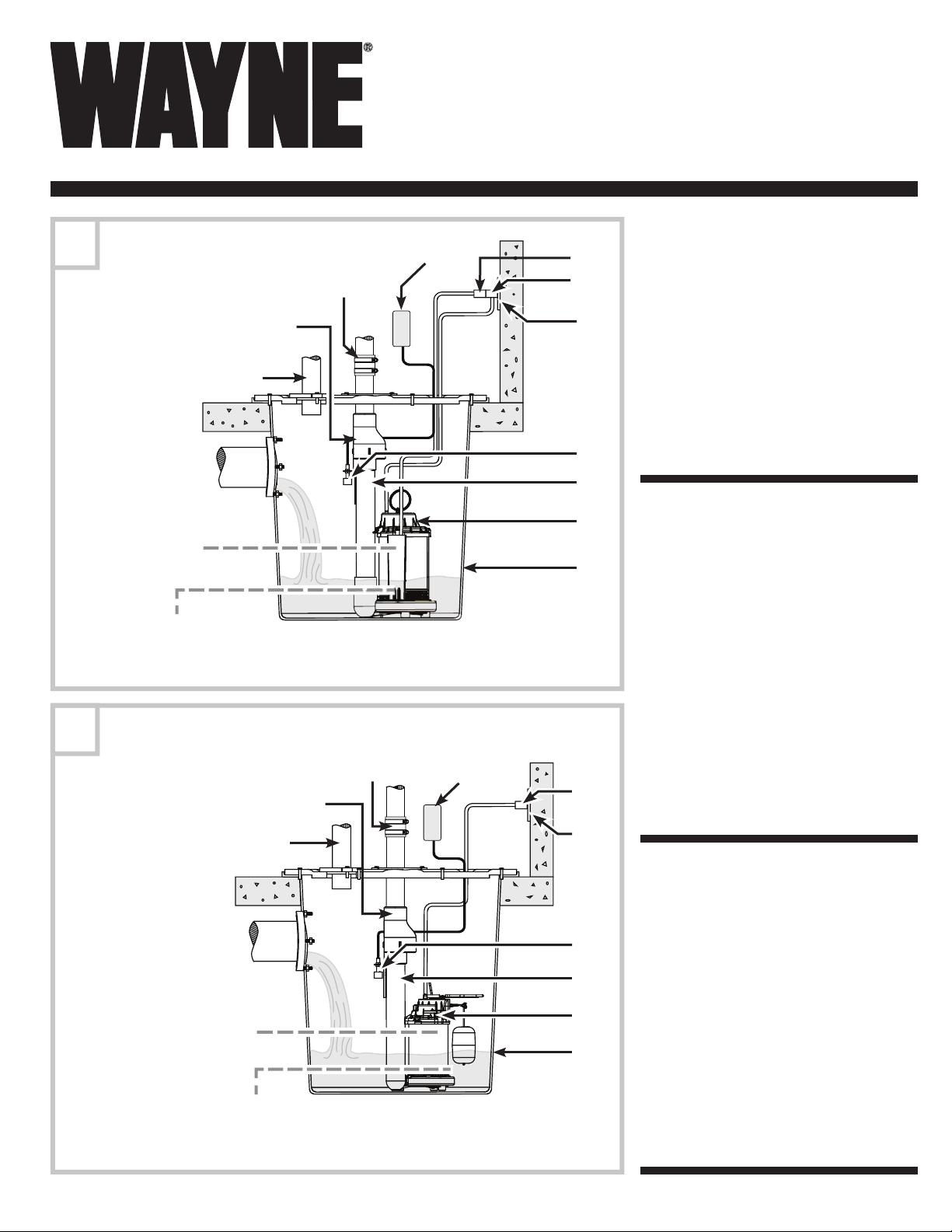
ISWITCH TYPICAL INSTALLATION
INSTALLATION TYPIQUE ISWITCH
A
INSTALACIÓN TÍPICA DE ISWITCH
2
3
ON LEVEL
(APPROX. 8 IN.)
NIVEAU DE COUPE
(ENVIRON 20 CM)
NIVEL DE ACTIVACIÓN
(APROXIMADAMENTE 20 CM)
OFF LEVEL (APPROX. 4 IN.)
NIVEAU DE DÉCOUPE (ENVIRON 10 CM)
NIVEL DE CORTE (APROXIMADAMENTE 10 CM)
FLOAT SWITCH TYPICAL INSTALLATION
INSTALLATION TYPIQUE D’INTERRUPTEUR À FLOTTEUR
B
INSTALACIÓN TÍPICA DEL INTERRUPTOR DE FLOTADOR
4
2
3
ON LEVEL
(APPROX. 9 IN.)
NIVEAU DE COUPE
(ENVIRON 23 CM)
NIVEL DE ACTIVACIÓN
(APROXIMADAMENTE 23 CM)
OFF LEVEL (APPROX. 4 IN.)
NIVEAU DE DÉCOUPE (ENVIRON 10 CM)
NIVEL DE CORTE (APROXIMADAMENTE 10 CM)
4
1
1
1
12
12
11
10
9
8
7
6
5
11
9
8
7
6
5
1. PVC COUPLER
2. CHECK VALVE
3. VENTILATION
4. INLET
5. BASIN
6. PUMP
7. DISCHARGE PIPE
8. FLOOD Alert ™ SWITCH
9. GFCI GROUNDED OUTLET
10. PIGGY-BACK PLUG
11. POWER CORD PLUG
12. FLOOD ALERT ™ TRANSMITTER
1. COUPLEUR PVC
2. CLAPET
3. VENTILATION
4. ENTRÉE
5. CUVE
6. POMPE
7. TUYAU DE DÉCHARGE
8. INTERRUPTEUR FLOOD ALERT
9. PRISE MISE À LA TERRE
PROTÉGÉE PAR DISJONCTEUR
DE FUITE À LA TERRE
10. FICHE SUPERPOSÉE
11. FICHE DE CORDON
D’ALIMENTATION
12. TRANSMETTEUR FLOOD
ALERT
1. ACOPLAMIENTO DE PVC
2. VÁLVULA DE RETENCIÓN
3. VENTILACIÓN
4. ENTRADA
5. PILETA
6. BOMBA
7. TUBERÍA DE DESCARGA
8. INTERRUPTOR FLOOD ALERT ™
9. TOMACORRIENTE GFCI
CONECTADO A TIERRA
10. ENCHUFE A CUESTAS
11. ENCHUFE DEL CABLE DE
CORRIENTE
12. TRANSMISOR FLOOD ALERT ™
™
™
www.waynepumps.com
1
550100-001 8/10
Page 2

SILENT SUMP SYSTEM
Please read and save these instructions. This manual contains important Safety Warnings and Operating Instructions. You will need to refer to it
before attempting any installation or maintenance. Always keep this manual with the unit so that it will be easily accessible. Failure to read and follow
these warnings and instructions could result in property damage, serious injury or death.
INSTALLATION GUIDE
DESCRIPTION
JOB-READY SILENT SUMP SYSTEM
This job ready sump pump system includes all the necessary
components required for direct system replacement and is
an automatic pump used to remove ground water from sump
pits. The most common application is for basement drainage
to prevent fl ooding in residential buildings. It is designed to
pump clear water only.
UNPACKING
Inspect your pump. Occasionally, products are damaged
during shipment. If the unit is damaged, return the unit to the
place of purchase for replacement.
This system should contain the following components:
• Sump pump • 1-1/2 inch PVC piping
• Flood Alert™ wireless sump • PVC coupler
pump monitoring system (with clamps)
• Silent Check Valve • Instruction Manuals (2)
READ & FOLLOW ALL INSTRUCTIONS OF ALL PROVIDED MANUALS
SAVE THESE INSTRUCTIONS — DO NOT DISCARD
ASSEMBLY
This system includes 1-1/2 inch
diameter piping. Any existing
plumbing other than 1-1/2 inch
will require an additional adapter
(not included).
1) Before modifying existing
sump plumbing, fully
assemble the silent sump
system. A fl at-head
screwdriver, PVC cement, and
PVC primer will be needed to
complete the assembly.
Read all
directions and
precautions on the PVC cement
and primer containers before
making the joint. Do not allow
PVC cement to come in contact
with inner workings of the
check valve.
2) Using PVC Cement and
Primer (both sold separately)
join the inlet side of the check
valve with the pre-installed
PVC discharge pipe. (Fig. 1).
NOTE: Raised lettering on
the check valve indicates the
direction of water fl ow
1
2
3) Next, attach the Flood Alert ™ wireless monitoring system
fl oat bracket directly below the silent check valve using
the included plastic zip-ties (Figure 2).
NOTE: Attach sump alarm fl oat to bracket when system is
connected to existing plumbing. See installation and set-up.
INSTALLATION & SET-UP
1) With the assembled silent
sump system as a height
reference, modify existing
plumbing to conform to
the silent sump system’s
overall height.
2) Using the provided rubber
PVC coupler and two
stainless steel clamps,
attach silent sump
discharge to existing
discharge plumbing
(Figure 3).
3) Attach the Flood Alert ™
fl oat switch to the
previously installed fl oat
bracket (Figure 4).
4) Refer to the wireless
sump pump monitoring
system manual for proper
transmitter placement.
5) Finish installation and
testing of the wireless
sump pump monitoring
system by using the
provided instruction
manual.
6) Refer to provided manuals for further installation testing
and troubleshooting.
7) After installation, check the system to ensure it is
operating properly.
To order a replacement check valve,
please call WAYNE at: 1-800-237-0987
Order part number 28211-002 for the check valve.
For additional replacement parts, refer to the provided
manuals for availability.
3
4
Existing
plumbing
www.waynepumps.com
2
Page 3

SYSTÈME DE POMPE DE PUISARD SILENCIEUX
Veuillez lire et conserver ces instructions. Ce manuel contient des instructions d’utilisation et des avertissements de sécurité importants. Il faudra s’y
reporter avant toute installation ou tout entretien. Toujours conserver ce manuel avec l’appareil pour qu’il soit facilement accessible. Ne pas lire et suivre
ces avertissements et ces instructions pourrait mener à des dommages à la propriété, à de graves blessures ou à la mort.
GUIDE D’INSTALLATION
DESCRIPTION
SYSTÈME DE POMPE DE PUISARD
SILENCIEUX PRÊT À UTILISER
Ce système de pompe de puisard prêt à utiliser inclut tous
les composants nécessaires et requis pour le remplacement
du système direct et est une pompe automatique utilisée
pour retirer l’eau souterraine des puisards. L’application la
plus courante est pour le drainage de sous-sol pour éviter
l’inondation des édifi ces résidentiels. Il est conçu pour
pomper seulement de l’eau propre.
DÉBALLAGE
Inspectez votre pompe. À l’occasion, les produits sont
endommagés durant l’expédition. Si l’appareil est endommagé,
retournez-le au site de l’achat pour remplacement.
Ce système devrait contenir les composants suivants :
• Pompe de puisard • Tuyau de PVC de 38 mm
• Système de vérifi cation (1 1/2 po)
de pompe de décharge • Coupleur PVC (avec pinces)
sans fi l Flood Alert ™
pump monitoring system
• Clapet de non-retour silencieux
LISEZ ET SUIVEZ TOUTES LES INSTRUCTIONS DE TOUS LES MANUELS
FOURNIS CONSERVEZ CES INSTRUCTIONS — NE JETEZ PAS
• Manuels d’instructions (2)
ASSEMBLAGE
Ce système inclut un tuyau de
38 mm (1 1/2 po) de diamètre.
Une plomberie actuelle autre
que celle de 38 mm
(1 1/2 po) exigera un adaptateur
supplémentaire (non inclus).
1) Avant de modifi er la plomberie
du puisard actuel, assemblez
tout le système de décharge
silencieux. Il faudra pour
l’assemblage, un tournevis à
lame plate, du ciment PVC et
une couche d’apprêt de PVC.
et précautions sur les contenant
d’apprêt et de ciment de PVC
avant de faire le joint. Ne laissez
pas le ciment PVC entrer en
contact avec les parties internes
du clapet de non-retour.
2) Utilisez le ciment et l’apprêt
de PVC (tous deux vendus
séparément) et joignez le
côté d’entrée du clapet de
non-retour avec le tuyau de
décharge de PVC pré-installé.
(Fig. 1).
Lisez toutes
les directives
1
2
REMARQUE : Les lettres en relief du clapet de non-retour
indiquent la direction de circulation d’eau
3) Installez ensuite la fi xation de fl otteur du système de
surveillance sans fi l Flood Alert ™ directement sous le
clapet de non-retour silencieux en utilisant les attaches à
glissière de plastique incluses (fi gure 2).
REMARQUE : Attachez le fl otteur d’alarme de décharge
à la fi xation lorsque le système est branché à la plomberie
actuelle. Reportez-vous
à l’installation et à la
confi guration.
INSTALLATION ET
CONFIGURATION
1) Avec le système de
pompe de puisard
silencieux assemblé
comme référence de
hauteur, modifi ez la
plomberie actuelle pour
vous conformer à la
hauteur d’ensemble
du système.
2) Utilisez le coupleur de
PVC de caoutchouc
fournir et les deux pinces
d’acier inoxydable,
et attachez la décharge
de pompe silencieuse à
la plomberie de décharge
actuelle (fi gure 3).
3) Fixez l’interrupteur à
fl otteur Flood Alert ™ à
la fi xation de fl otteur déjà
installée (fi gure 4).
4) Reportez-vous au
manuel du système de
surveillance de pompe
de puisard sans fi l pour le
placement approprié du transmetteur.
5) Finissez l’installation et le test du système de surveillance
de pompe de puisard sans fi l en utilisant le manuel
d’instructions fourni.
6) Reportez-vous aux manuels fournis pour tout autre test
d’installation et dépannage.
7) Après l’installation, vérifi ez le système pour vous assurer
qu’il fonctionne correctement.
Pour commander un clapet de non-retour de rechange,
appelez WAYNE au : 1-800-237-0987
Commandez le numéro de pièce 28211-002 pour le
clapet de non-retour.
Pour obtenir d’autres pièces de rechange, reportez-vous aux
manuels fournis pour leur disponibilité.
3
4
Plomberie
actuelle
3 Fr
Page 4

SISTEMA SILENCIOSO DE SUMIDERO
Sírvase leer y guardar estas instrucciones. Este manual contiene Advertencias de seguridad e Instrucciones de funcionamiento. Deberá consultar el mismo
antes de realizar cualquier instalación o mantenimiento. Siempre mantenga este manual con la unidad de forma de acceder al mismo fácilmente. No leer ni
respetar estas advertencias e instrucciones podría dar como resultado daño a la propiedad, lesiones graves o la muerte.
GUÍA DE INSTALACÍON
DESCRIPCIÓN
SISTEMA SILENCIOSO DE SUMIDERO LISTO
PARA EL TRABAJO
Este sistema de bomba de sumidero listo para el trabajo
incluye todos los componentes necesarios requeridos
para el reemplazo del sistema directo y es una bomba
automática que se usa para extraer agua de sumideros.
La aplicación más común es el drenaje de sótanos para
evitar inundaciones en edifi cios residenciales. Está diseñada
para bombear sólo agua limpia.
DESEMPAQUE
Inspeccione su bomba. En ocasiones, los productos
se dañan durante el envío. Si la unidad está dañada,
devuélvala al lugar de compra para obtener un reemplazo.
Este sistema debe contener los siguientes componentes:
• Bomba para sumidero
• Sistema inalámbrico de • Acoplador de PVC
monitoreo para la bomba (con abrazaderas)
de sumidero Flood Alert™ • Manuales de
• Válvula de retención instrucciones (2)
silenciosa
LEA Y SIGA TODAS LAS INSTRUCCIONES DE LOS MANUALES
PROPORCIONADOS CONSERVE ESTAS INSTRUCCIONES
— NO LAS DESECHE
• Tubería de PVC de 1-1/2 pulg.
ENSAMBLAJE
Este sistema incluye tuberías
de 1-1/2 pulg. de diámetro.
Cualquier otra tubería existente
además de la de 1-1/2 pulg.
requerirá un adaptador
adicional (no se incluye).
1) Antes de modifi car una
tubería de sumidero existente,
arme totalmente el sistema
silencioso de sumidero.
Necesitará un destornillador
de cabeza plana, cemento
para PVC e imprimador
de PVC para completar
el ensamblaje.
Lea todas las
instrucciones y
precauciones de los recipientes
de cemento de PVC e imprimador
antes de realizar la junta. No deje
que el cemento de PVC entre en
contacto con la mecánica interna
de la válvula de retención.
2) Usando el cemento de PVC
y el imprimador (ambos se
venden por separado) una
el lado de la entrada de la
válvula de retención con la
tubería de descarga de PVC
previamente instalada. (Fig. 1).
1
2
NOTA: las letras con relieve de la válvula de retención
indican la dirección del fl ujo de agua
3) A continuación, coloque el soporte fl otante en el sistema
inalámbrico de monitoreo Flood Alert ™ (alerta de
inundación) directamente por debajo de la válvula de
retención silenciosa usando las abrazaderas plásticas
incluidas (Figura 2).
NOTA: conecte el fl otador de la alarma de sumidero
al soporte cuando
el sistema se conecte
a la tubería existente.
Vea instalación y montaje.
3
Tubería
existente
INSTALACIÓN
Y MONTAJE
1) Con el sistema de
sumidero silencioso
armado como referencia
de altura, modifi que la
tubería existente para
adaptarlo a la altura
total del sistema de
sumidero silencioso.
2) Usando el acoplador
de goma para PVC
proporcionado y dos
abrazaderas de acero
inoxidable, conecte la salida
de sumidero silencioso
a la tubería de descarga
existente (Figura 3).
3) Conecte el interruptor de
fl otador Flood Alert
(alerta de inundación)
al soporte de fl otador
previamente instalado
(Figura 4).
4) Consulte el manual
del sistema inalámbrico de monitoreo de la bomba
de sumidero para conocer la ubicación correcta del
transmisor.
5) Termine la instalación y la prueba del sistema inalámbrico
de monitoreo de la bomba de sumidero usando el manual
de instrucciones proporcionado.
6) Consulte los manuales proporcionados para obtener
más pruebas y resolución de problemas de la instalación.
7) Después de la instalación, verifi que el sistema para
asegurarse de que esté funcionado correctamente.
Para pedir una válvula de retención de repuesto,
llame a WAYNE al: 1-800-237-0987
Pida el número de pieza 28211-002 para la válvula
de retención.
Para piezas de repuesto adicionales, consulte los manuales
proporcionados para saber la disponibilidad de las mismas.
™
4
4 Sp
 Loading...