

Page 1

SERVICE
3/Vista Series
Blending and
Non-Blending
Dispensers
Page 2

READ THIS MANUAL BEFORE YOU BEGIN
Dispensers have both electricity and a hazardous, flammable and potentially explosive liquid. Failure to
follow the below precautions and the Warning and Caution instructions in this manual may result in serious
injury. Follow all rules, codes and laws that apply to your area and installation.
SAFETY PRECAUTIONS - INSTALLATION AND MAINTENANCE
Always make sure ALL power to the dispenser is turned OFF before you open the dispenser cabinet for
maintenance. Physically lock, restrict acces s to , o r tag th e cir cuit brea kers you turn off when servicing th e
dispenser. Be sure to trip (close) the emergency valve(s) under the dispenser BEFORE beginning
maintenance.
Make sure th at yo u kn ow how to t urn OF F po w er to t he di spen ser an d sub me rsi bl e pu mp s in an e mer g e nc y.
Have all leaks or defects repaired immediately.
EQUIPMENT PRECAUTIONS
Be sure to bleed all air from product lines of remote dispensers and prime suction pumps before dispensing
product, otherwise, damage to the equipment may occur. Always use the approved method for lifting the
dispenser. Never lift by the nozzle boot, sheet metal, valance, etc., otherwise equipment damage or personal injury may occur.
HOW TO CONTACT WAYNE
Trouble with the installation and operation of the dispenser should be referred to your authorized Wayne
service personnel or Wayne Technical Support (1-800-926-3737).
INDICATORS AND NOTATIONS
Danger indicates a hazard or unsafe practice which, if not avoided, will result in severe injury
or possibly death.
Warning indicates a hazard or unsafe practice which, if not avoided, may
result in severe
injury or possibly death.
Caution indicates a hazard or unsafe practice which, if not avoided, may
result in minor inj ury.
NOTE:
Important information to consider, otherwise, improper installation and/or damage to components may occur.
DANGER
DANGER
WARNING
CAUTION
Page 3

June 2001 Part No. 920525 Rev A
3/Vista Series
Blending and
Non-Blending
Dispensers
Service
Page 4

Part No. 920525 Rev A June 2001
Page 5
1
June 2001 Part No. 920525 Rev A
1. INTRODUCTION
This manual describes the service of Wayne Vista series blending and non-blending dispense rs that have a
"3" in the prefix of the model number. For example, 3/V390D1/GQUY. Again, these dispensers can be identified by their model which begins with “3/V”, hereafter, referred to as 3/Vista models. The basic troubleshooting methods and service theory will remain the same for all models of dispensers which satisfy the
above definition. Any information which is specific to a particular model of dispenser will be shown as
specific in the text.
Non-blending dispensers included in this manual are the 3/V387, 3/V388, 3/V389, 3/V390, 3/V399 and
3/V490 models. Non-blending dispensers do not combine base products. These dispensers are multi-grade
dispensers, except for the 3/V387 single grade model.
Blending dispensers included in this manual are the 3/V580, 3/V585, 3/V590, 3/V591, and 3/V595 models. Blending dispensers combine the ba se products to provide a blended grade or grades. Blending di spensers have two base products labeled LO and H I. These base products ma y be dispense d individually
and/or combined into one or more blended grades. The 3/V591 and 3/V595 models also have an additional
single-product (unblended) grade, however, the 3/ V595/U does not.
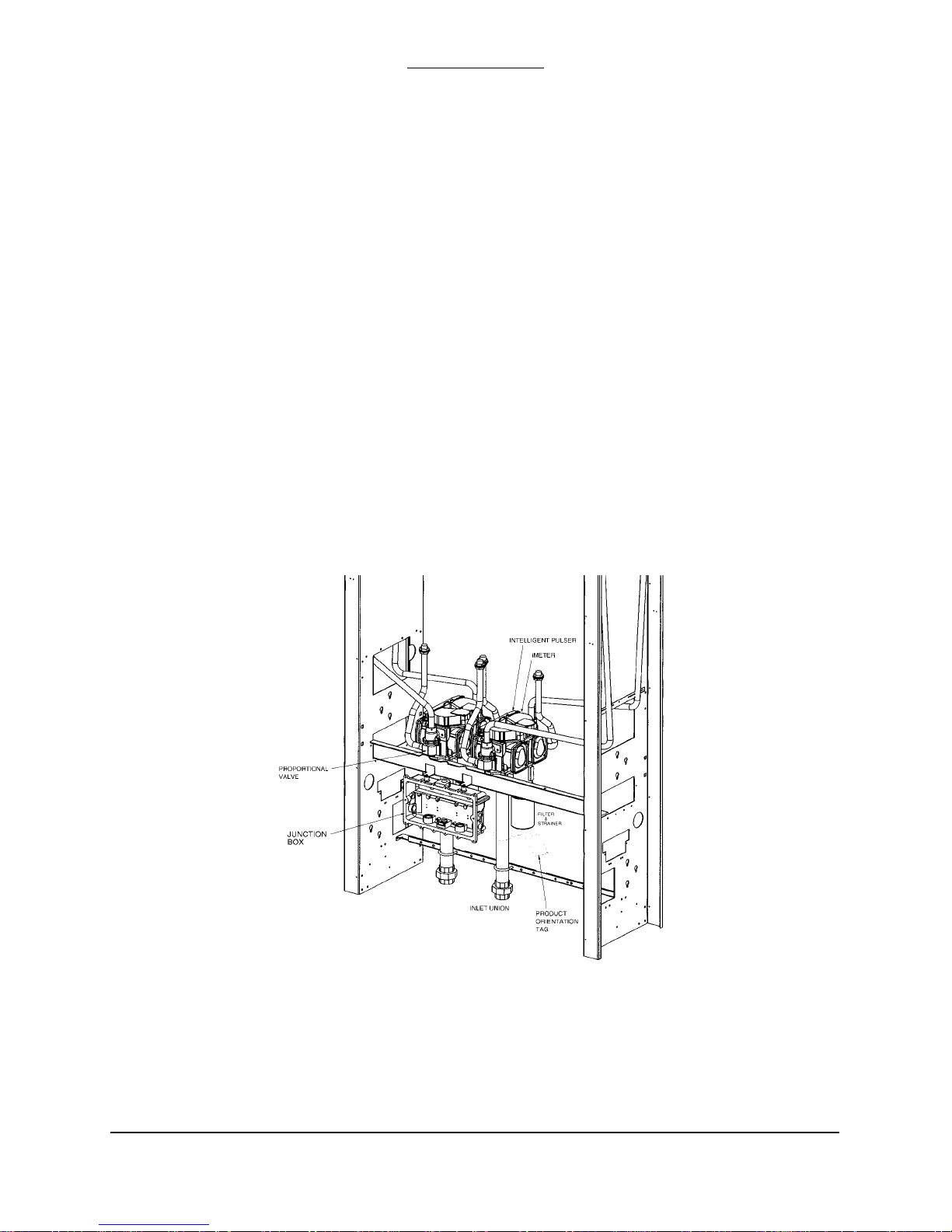
3/Vista series dispensers have a new computer - and associated boards - and a sales display board mounted
on the back of the new bezel.
The new computer in 3/Vista series dispensers controls the hydraulic module that was newly designed and
introduced in the 2/Vista series. The hydraulic modu le consists of the iMeter Module and the Intelligent
Pulser. The iMeter Module is two meters in one assembly and contains the Intelligent Pulser.
.
FIGURE 1-1. 3/VISTA DISPENSER. Porportional val ves are mounted at the iMeter outlet on 3/Vista
model dispensers.
Page 6

2
Part No. 920525 Rev A June 2001
1.1. REGIONAL SERVICE OFFICES
Any service problems that cannot be solved should be refered to Wayne Technical Support
or to the appropria te regional servic e office.
Wayne Tech nical Support 1-800-926-3737
Austin, TX 24 hours/7 days
Northeast Regi ona l 410-546-675 0
Service Office 8:30AM-5:00 PM Eastern
Salisbury, MD
Southeast Regiona l 770-926-6005
Service Office 8:30AM-5:00PM Eastern
Atlanta, GA
North Central Regional 773-693-7404
Service Office 8 :30 AM-5:00PM Central
Chicago, IL
South Central Regional 281-871-5442
Service Office 8 :30 AM-5:00PM Central
Houston, TX
Southwest Regional 714-952-1137
Service Office 8:30AM-5:00PM Paci fic
Cypress, CA
Northwest Regional 510-328-0400
Service Office 8:30AM-5:00PM Pacific
San Ramon, CA
Mid-Atlantic Regi ona l 410-6 91-2200
Service Office 8:30AM-5:00PM Eastern
Baltimore, MD
INTERNATIONAL OFFICES
Caribbean and Latin America (Voice) 512-388-8624
Service Office (FAX) 512-388-8643
Austin, TX USA
Mid-East and Afri ca (Voice) 44-1635 -874881
Service Office (FAX) 44-1635 -876633
United Kingdom
Far East (Voice) 65-422-2397
Service Office (FAX) 65-225- 6604
Singapore
Page 7

3
June 2001 Part No. 920525 Rev A
2. OPERATION
The ope ration fo r all 3/V ista se ries dis penser s is simi lar , ex cept wher e disti nguished below between
lift-to-start and push-to-st art mo de ls.
Before the dispenser will reset unit prices must be set and an authorization signal must be received,
and if a blender model, blend ratios must be set. The unit prices, authorization, and blend ratios can
be manually set at the dispenser for stand-alone operation, or from a control system, after first setting
the fueli n g point ID .
The above requi rements are discussed in deta il in t hi s section. Once they have been satisfied, the
dispenser oper at es as de scribed in the followi ng sections.
2.1. LIFT-TO-START MODELS
• When the no zzle is r emov ed f rom the n ozzl e bo ot an d th e l ever is li ft ed, t he co nst ant +5
VDC that the computer supplies to th e nozzle switch goes to g round. This signals the
computer to be gin its reset cyc le .
• When the di spens er rece iv es a n Authorization signal either fro m the co ntro l syste m or,
if stand -al on e, f rom th e di spe nse r, t he cor rect su bmer sib l e pu mp re la y wi ll be e ne rgi ze d.
• The computer p erforms a self test an d flashes eights, bla nks , then resets to z er o s, on the
main sale display.
• After the dispenser resets, the proportional flow control valve (or valves if a blender
model) is energize d w i th j ust e nough current to barel y open the valve and all ow a slo w
flow.
After a small amount of fuel has been di s p ensed, the valve is energized with enoug h
current to be in the fully open position and allow fast flow. During the sale, the valve will
be continuously controlled with the proper amount of current to limit fuel flow rate to a
maximum of 10 GPM
*
, and if a blende r model, provide the correct blend rati o.
• In preset sales, the current received by the proportional flow control valve(s) is
reduced to the barely open position ju st pri or to the final shut-off amo unt. The valve(s)
is then de-energi ze d when the final amount is reached .
• When the lever is lowered, the nozzle switch goes b ack to the c onstant +5 VDC, the sale
is complete, an d th e nozzle is returned to the nozzle boot.
2.2. PUSH-TO-START MODELS
• When the nozzle is removed from the nozzle boot, the constant +5 VDC that the
computer suppl ie s to th e noz zle switch goes to ground. At this point, on e of th e l ighted
buttons (grade select, cash/credit, or push-to -start , de pe ndi ng model) will flash indicating that one of th e buttons must be pressed.
• When one of the lighted buttons is pressed the constan t +5 VDC that is supplied to the
switch goes to ground. This signals the comput er t o begin its reset cycle.
• When the disp en s er r eceives an Authorization signal either from the contr ol system or
from the Auth orize switch in the di s p enser, the correct submersible pump r e lay will be
energized.
* The maximum allowable flow rate in the United States is 10 gallons per minute.
Page 8

4
Part No. 920525 Rev A June 2001
• The computer perform s a se lf t est and fl ashes eights, blanks, then resets to zeros, on the
main sale displ ay.
• After the dispenser resets, the proportional flow control valve (or valves if a blender model)
is energized wi th j ust e nough current to barely open the valve a nd allow a slow flow.
After a small amou nt of fuel has been dispensed, the valve(s) is energized with e nough
current to be in the fully open position and allow fast flow. During the sale, the valve(s) will
be continuously controlled w it h the proper amount of c urre nt to limit fuel flow rat e t o a
maximum of 10 GPM
*
, and if a blender model, provide the correct blend rat io.
• In preset sales, the curre nt rec eived by the proportiona l flow c ontrol valve(s) is
reduced to the bare ly open position just prior to t he fi na l shut -off amount. The valve(s) is
then de-energized when the fina l a m ount is reached.
• When the nozz le is re turne d to the nozz le b oot, the nozzle swit ch g oes b ack t o th e co nstan t
+5 VDC and the sale is complete.
2.3. SETTING UNIT PRICES
The procedure below is used to set the dispenser unit prices when operating in stand alone mode
or when communication with the POS system is disabled. When enabled , th e P OS sys tem will
not allow price setti ng at the dispenser.
The pump comput e r rec ognizes code stored in mem ory t ha t de fin es a di spe nse r model and
assigns logical nozzle numbers t o the hose positi ons as shown in (Table 2-1). To set unit prices
on side 1 an d s i de 2, functions F03 and F04 are accessed usin g th e re mo te control interface.
Credit prices on side 1 are set using sub-functions F03.0N while cash prices are set using subfunctions F03.1N, where N is the logical nozzle number. Active values of N are given in Table 2-
1. For side 2, the corresponding sub-functions are F04.0N a nd F04.1N, respec tively.
To set the unit pric e, the correct sub-function is accessed, the uni t price is changed to its new
value and the data is saved. To access the desired sub-function, perform the following steps using
the remote contr ol. Bold type denotes remote control function; italicized type denotes dispenser
response.
Accessing the Unit Price Sub-function for Side 1
1. Press ENTER
PASS 1 (enter password )
2. Press ENTER
PASS 2 (enter password )
3. Press ENTER. The unit price display will show F— (indicating it needs a function number
to proceed)
4. Press 03 to access F03
5. Press ENTER. The unit price display w i ll show F03 (indicating the fu nction has been
accessed)
6. Press ENTER to acce ss the sub-functions of F03. The unit price display will show 3.01.
* The maximum allowable flow rate in the United States is 10 gallons per minute.
Page 9

5
June 2001 Part No. 920525 Rev A
At this point, pressing of NEXT will advance the sub-function to the next sub-function, incrementing the
value of N by (.01). For example, to access F3.02, press NEXT. The unit price display wi ll show 3.02,
press NEXT. The desired sub-function dep end s on the dispenser type. Table 2-1 shows the values of N
that define the desired sub-functions for the dispensers shown. Once the desired sub-function is accessed,
the price display wil l sho w “– – – – – –“ and the volume display will show the curren t va lue of the unit
price. The following procedure must then be followed to set the unit price.
Changing the Value of the Unit Price
Type in the new unit price with at least thr ee dig it s for three money display di git s to be show n after the
decimal poi nt .
*
For exam ple, to set the new unit price to $1.50, type in 1500. Type in 1509 for $1.509
unit price.
1. Press #. The volume display will show the unit price with the correct number of digits after the decimal point.
Again, for the example above, the volume display will show 1.500.
2. Press NEXT to input the next unit price, and repeat steps 1 and 2. Continue until all the unit prices are input
and Save the unit prices as per the following procedure: Note that while inputting the unit prices, the unit price
display continues to show the sub-function and not the unit price itself.
Saving the New Unit Prices
1. Press ENTER. The price display will show “– – – – – –“, the volume display will be blank and the unit price display
will show the last sub-function accessed.
2. Press 00 (to access F00)
3. Press ENTER. The unit p ri ce should now display F00, the price display will show “– – – – – –“ and the volume dis-
play will be blank.
4. Press ENTER and the volume display will show a 1.
5. Press UP twice to change the value in the volume display from 1 to 3
6. Press ENTER. The volume display shou ld show a 3.
7. Press ENTER. CHANGE STORED should appear on the display momentarily. The display should return to normal
in a few seconds. When it does, the unit price displays should show the new prices. If they do not show the desired
unit prices, access the appropriate sub-function to make sure that the unit price data is correct.
T ABLE 2-1 Hose Positions Defined by Values of N.
* This is the default mode. The number of digits after the decimal points is set in function F14.02.
DISPENSER
TYPE
N=7 N=6 N=5 N=4 N=3 N=2 N=1
3/V595 (4+1) Lo
Feedstock
Lo-BL Hi-BL HI
Feedstock
Single
Grade
3/V595 (3+1) Lo
Feedstock
BL HI
Feedstock
Single
Grade
3/V595/U Lo
Feedstock
Lo-BL Mid–BL Hi-BL HI
Feedstock
3/V595/U (4) Lo
Feedstock
Lo-BL Hi-BL HI
Feedstock
Page 10

6
Part No. 920525 Rev A June 2001
2.4. BLEND RATIO SETTING
Function F18 is acce s s e d to set the blend ra tios, using the re mote con tr ol interf ace. The sub-fun ction
F18.1N, where N is the logical nozzle number, is used to set the blend ratios for side 1 and the sub-function
F18.2N is used to se t the blend ratios for side 2. Acti ve val ues of N are given in T able 2-1.
Bold type denote remote cont rol function and italicized type represe nts dispenser response):
Accessing the Blend Ratio Sub-function for Side 1
1. Press ENTER
PASS 1 (enter passwor d)
2. Press ENTER
3. PASS 2 (enter passw ord)
4. Press ENTER. The unit price displ a y w ill show F— (indicating t ha t it nee ds a function number t o
proceed).
5. Press 18 to access F18
6. Press ENTER. The unit price display will show F18 (indicating that the function has been accessed).
7. Press ENTER to access the sub-functions of F18. The unit price display will show 18.11 (here N=1).
The volume disp la y w il l i ndicate the valu e of the blend ratio corresponding to lo gi cal nozzle #1( N=1). If
there is no data for this logical nozzle, the number “101” will be displayed. This ap plies to all logical
nozzles. To access the blend ratio for the next logical nozzle, press NEXT. The unit price display will show
18.12 and the volume display will show whatever the value of the blend ratio is for logical nozzle #2. Subsequent pressing of NEXT will advance the unit price display to 18.17, the last lo gical nozzl e. Pressing NEXT
again will ad va nce the unit price display to 18.21
, The “2” in “18.21” indicates Side 2 and the “1”, logical
nozzle #1. The volume display will show the bl end ratio assigned to logical nozzle #1 of Side 2 .
3/V580 Lo
Feedstock
BL HI
Feedstock
3/V585 Lo
Feedstock
Lo-BL Mid–BL Hi-BL HI
Feedstock
3/V590 HI
Feedstock
BL Lo
Feedstock
3/V590/U Lo
Feedstock
BL HI
Feedstock
3/V591 Lo
Feedstock
BL HI
Feedstock
Single
Grade
3/V490/U AA Z Y X
3/V490 AA Z Y X
3/V390 Z Y X
3/V399 Y X
3/V389 Y X
3/V387 X
Page 11

7
June 2001 Part No. 920525 Rev A
Changing the Value of the Blend Ratio
8. When the desired logical nozzle is shown on the unit price display, enter the desired value of the blend
ratio by using UP and DOWN keys on the remote con tr o l interface or by typing the # sign followed
by the value of t h e bl end ratio, followe d by ENTER. For exampl e, to change the value of the bl en d
ratio from 101 to 89, press the DOWN button unt il 89 shows up on the price display, then press
ENTER, or type in #89, ENTER.
9. Contin u e until all the blend ratios are entered for Side 1 an d S i d e 2 an d save the setti ng s a s fo l lows:
10. Press ENTER. The price display will show “– – – – – –“, the volume display will be blank and the unit
price display will show the last sub-function accessed.
11. Press 00 (to access F00)
12. Press ENTER. The unit price should now display F00, th e pri ce display will show “– – – – – –“ and
the volume displ ay will be blank.
13. Press ENTER and the volume disp la y wil l sho w a 1.
14. Press UP twice to change the value in the volu me display from 1 to 3.
15. Press ENTER. The volume disp lay should show a 3.
16. Press ENTER. C HANGE STORED should appear on the di splay momentaril y. The disp la y shoul d
return to normal in a few seconds. When it does, the unit price displays should show the new prices. If
they do not show the desired unit prices, access the appropriate sub-function to make sure that the unit
price data is correct.
2.5. SETTING THE FUELING POINT ID
The procedure below is used to set the dispenser fueling point address. The dispenser FPID should be input and saved
before control is transferred to the POS system.
Functions F05 and F06 are accessed to set the FPID on Side 1 and Side 2, respectively. To set the FPID, the desired FPID
must be input and saved.
Accessing the FPID Function for Side 1
1. Press ENTER
PASS 1 (enter password)
2. Press ENTER
PASS 2 (enter password)
3. Press ENTER. The unit price display will show F— (indicating that it needs a function number to proceed)
4. Press 05 to access F05
5. Press ENTER. The unit price display will show F05 indicating the function has been accessed and the volume display
will show the current FPID or a “0” when no FPID has been assigned to that dispenser side.
6. Input the desired FPID by using the UP and DOWN keys on the remote control interface followed by ENTER, or by
typing the # sign followed by the valve of the FPID followed by ENTER.
7. Repeat the procedure for Side 2.
Page 12

8
Part No. 920525 Rev A June 2001
Saving the New FPID
1. Press ENTER. The price display will show “– – – – – –“, the volume display will be blank and the unit price display
will show the last sub-function accessed.
2. Press 00 (to access F00)
3. Press ENTER. The unit price sho uld now disp la y F00, the price display will show “– – – – – –“and the volume display
will be blank.
4. Press ENTER and the volume display will show a 1.
5. Press UP twice to change the value in the volume display from 1 to 3.
6. Press ENTER
7. The volum e display should show a 3.
8. Press ENTER. CHANGE STORED should appear on the display momentarily. The display should return to normal in
a few seconds. When it does, the unit price displays should show the new prices. If they do not show the desired unit
prices, access the appropriate sub-function to make sure that the unit price data is correct.
8. Repeat the procedure for Side 2.
2.6 AUTHORIZING THE DISPENSER
The dispenser must be authorized before it will dispense product.
In stand-alone operation, not connected to a control system, the dispenser is always authorized, unless the dispenser is
equipped with the (optional) Authorize keyswitch on the bezel. This momentary contact keyswitch can be used for one
time authorizations.
When connected to a control system, the system programming determines authorization.
Page 13

9
June 2001 Part No. 920525 Rev A
3. BOARD LAYOUTS, INDICATORS AND PINOUTS
Page 14

10
Part No. 920525 Rev A June 2001
3.1 COMPUTER BOARD LED INDICATORS)
Processor Activity Indicator
DS1: Red (Heartbeat) LED indicates processor activity. It will be blinking on and off at a steady rate as long as
the processor is running properly .
Power Indicators
These LEDs only indicate the presence of a voltage. They do not assure that the levels are correct.
DS6: Green LED indicates that the board is connected to power source on its 24VDC input line.
DS7: Green LED indicates that the board is generating 5VDC to power the logic.
DS8: Green LED indicates that the board is generating 8VDC for use on board and to power
associated assemblies.
DS13: Green LED indicates that the board is generating 15VDC which is used to power
the attached WIPs.
DS14: Green LED indicates that the board is generating 5VDC for use onboard.
Communication Activity Indicators
POS Communications:
DS5: Red LED indicates activity on the Host Receive Line. The LED is on when the line is low.
DS12: Green LED indicates activity on the Transmit Line. The LED is on when the line is low.
Display Bi t Bus Side 1 and 2 Communications:
DS3: Red LED indicates activity on Receive Line. The LED is on when the line is high.
DS9: Green LED indicates activity on the Transmit Line. The LED is on when the line is high.
WIP (Pulsers) Communications:
DS4: Re d LED indicates activity on Receive Line. The LED is on when the line is low.
DS11: Green LED indicates activity on the Transmit Line. The LED is on when the line is low.
CAN Bus Communications (Future Use for Harmony, eVista, Ovation):
DS2: Re d LED indicates activity on Receive Line. The LED is on when the line is low.
DS10: Green LED indicates activity on the Transmit Line. The LED is on when the line is low.
Page 15

11
June 2001 Part No. 920525 Rev A
3.2 COMPUTER BOARD CONNECTOR PINOUTS
Connector
and Pin #
Description Connects To Note
J1 24 VDC In 24V DC Distribution Bd J4 Typical Reading 24V
1 24V
2 24V
3GND
4GND
J2 Sub Pump Relays Relay Board J1 Typical Readings 24V
1 24 VDC
2Pump Motor 2
3 24 VDC
4Pump Motor 1
5 24 VDC
6Pump Motor 4
7 24 VDC
8Pump Motor 3
J3 Valve Outputs Proportional Valves
Pin
1GND
Typical Voltage Readings
for checking the operati on
of the proportional valves.
All valves
MGDs: slow flow 8Vdc
fast flow 19 Vdc
Blender: slow flow or fast
flow 8-19 Vdc
2 Valve #9 24V
3GND
4 Valve #4 24V
5GND
6 Valve #3 24V
7GND
8 Valve #2 24V
9GND
10 Valve #1 24V
11 GND
12 Valve #10 24V
13 GND
14 Valve #8 24V
15 GND
16 Valve #7 24V
17 GND
18 Valve #6 24V
19 GND
20 Valve #5 24V
Page 16

12
Part No. 920525 Rev A June 2001
3.2 COMPUTER BOARD CONNECTOR PINOUTS, CONTINUED
Connector
and Pin #
Description Connects To Note
J4 Nozzle Switch Inputs ISB J7 Typical Reading 5V
1GND
2 NOZZ 4
3GND
4 NOZZ 3
5 GND
6 NOZZ 2
7GND
8 NOZZ 1
9GND
10 NOZZ 8
11 GND
12 NOZZ 7
13 GND
14 NOZZ 6
15 GND
16 NOZZ 5
J5 WIP IN/OUT ISB J1 Typical Reading 14.8-15.2V
1 15 VDC
2GND
3WIP1 REC
4WIP1 TX
5GND
6WIP2 REC
7WIP2TX
8GND
9GND
10 WIP3 REC
11 WI P3 TX
12 GND
13 WIP4 REC
14 WIP4 TX
15 GND
16 15 VDC
Page 17

13
June 2001 Part No. 920525 Rev A
3.2 COMPUTER BOARD CONNECTOR PINOUTS, CONTINUED
Connector
and Pin #
Description Connects To Note
J6 Totalizers from Side1 Outputs from Tots 1-4
1 24V
2TOT 1
3 24V
4TOT 2
5 24V
6TOT 3
7 24V
8TOT 4
9N/C
10 N/C
J7 Totalizers from Side2 Outputs from Tots 5-8
1 24V
2TOT5
3 24V
4TOT6
5 24V
6TOT7
7 24V
8TOT8
9N/C
10 N/C
J8 BackLight Output
1 SIDE A 24V
2GND
3 SIDE B 24V
4GND
J9 Red/Green Light
Outputs
1 SIDE A 24V
2GND
3 SIDE B 24V
4GND
J10, J11, J12 SPARE IN/OUT
Page 18

14
Part No. 920525 Rev A June 2001
J13 CAN BUS I/O Future use for Harmony,
eVista, Ovation
1 TX/RC +
2 TX/RC 3 24V
4GND
J14 Euro DataLink Not used in US
J15 Display Data Cable
Bit Bus Side A (1)
Side 1 Display J1
1DATA IN A
2DATA OUT A
3 ADDRESS BIT A
4CLOCK A
5 BUZZER A
6STOP A
7 8 VDC Typ r eads 8.1 V
8GND
9REMOTE
10 GND
J16 Display Data Cable
Bit Bus Side B (2)
Side 2 Display J1
1DAT IN B
2DATA OUT B
3 ADDRESS BIT B
4CLOCK B
5 BUZZER B
6STOP B
7 8VDC Typ r eads 8.1 V
8GND
9REMOTE
10 GND
J21 BUZZER POWER
SIDE 2
18V
2 BUZZER 2
Page 19

15
June 2001 Part No. 920525 Rev A
3.2 COMPUTER BOARD CONNECTOR PINOUTS, CONTINUED
Connector
and Pin #
Description Connects To Note
J22 BUZZER POWER
SIDE 1
18V
2 BUZZER 1
J23 CAT BUZZER
1GND
2BUZZ CAT
J24 WAYNE VAC WAYNE VAC BD J2
1 V AC CONNECTED
(YES/NO)
2 FREEZING TEMP Thermostat
3 WAYNE VAC ID 0
4 WAYNE VAC ID 1
5ORVR B
6 MOTOR SPEED B
7 MOTOR STATUS B1
8 MOTOR STATUS B0
9ORVR A
10 MOTOR SPEED A
11 MOTOR STATUS A1
12 MOTOR STATUS A0
13 RUN MOTOR A
14 DIR MOTOR A
15 RUN MOTOR B
16 DIR MOTOR B
17 RESET
18 GND
19 CLOCK
20 GND
J25 DATALINK DATALINK PAIR 1
1DATA +
2DATD -
Page 20

16
Part No. 920525 Rev A June 2001
3.3 ISB BOARD CONNECTOR PINOUTS
Connector
and Pin #
Description Connects To Note
J1 WIP Pulsers 1-4 Computer J5
1POWER 1 15V
2GND
3 RC 1
4TX 1
5GND
6 RC 2
7TX 2
8GND
9GND
10 RC 3
11 TX 3
12 GND
13 RC 4
14 TX 4
15 GND
16 POWER 2 15V
J2 TO PULSER 1
1TX
2RC
3GND
4 15V
5N/C
6N/C
7N/C
8N/C
J3 TO PULSER 2
1TX
2RC
3GND
4 15V
5N/C
6N/C
7N/C
8N/C
Page 21

17
June 2001 Part No. 920525 Rev A
3.3 ISB BOARD CONNECTOR PINOUTS, CONTINUED
Connector
and Pin #
Description Connects To Note
J4 TO PULSER 3
1TX
2RC
3GND
4 15V
5N/C
6N/C
7N/C
8N/C
J5 TO PULSER 4
1TX
2RC
3GND
4 15V
5N/C
6N/C
7N/C
8N/C
J7 Nozz Switch
Outputs
Computer J4
Typ 5V
1NOZ 1
2NOZ 2
3NOZ 3
4NOZ 4
5NOZ 5
6NOZ 6
7NOZ 7
8NOZ 8
9GND
10 GND
Page 22

18
Part No. 920525 Rev A June 2001
J6 NOZZ Switch
INPUTS
Nozzles
1NOZ 1
2NOZ 2
3NOZ 3
4NOZ 4
5GND
6NOZ 5
7NOZ 6
8NOZ 7
9NOZ 8
10 GND
Page 23

19
June 2001 Part No. 920525 Rev A
3.4 24V DC DISTRIBUTION BOARD CONNECTOR PINOUTS
Connector
and Pin #
Description Connects To Note
J1 24V P/S J2
1 24V IN
2 24V IN
3GDN
4GDN
J2 BATTERY EXTERNAL
1 24V
2 24V
3GDN
4GDN
J3 24V OUT Wayne Vac Board J6
1 24V OUT
2 24V OUT
3GDN
4GDN
J4 24V COMPUTER J1
1 24V
2GDN
J5 24V SPARE OUT
J6 24V DUAL CAT BD
1 24V
2GDN
J7 24V SPARE OUT
J8 24V PRINTER 1
1 24V
2
3 24V
4GDN
5GDN
6GDN
J9 24V PRINTER 2
1 24V
2
3 24V
4GDN
5GDN
6GDN
Page 24

20
Part No. 920525 Rev A June 2001
3.5 WAYNE VAC CONTROL BOARD PINOUTS
Connector
and Pin #
Description Connects To Note
J1 IS ISB Connection
15V
2GND
35V
4
55V
6N/C
7N/C
8N/C
95V
10 GND
J7 VAC MOTOR A VAC MOTOR A
15V
25V
35V
45V
5GND
6V MOTOR
7 SW 24V
8PHASE A
9PHASE B
10 PHASE C
J8 TO VAC MOTOR B VAC MOTOR B
PIN
15V
25V
35V
45V
5GND
6V MOTOR
7 SW 24V
8PHASE A
9PHASE B
10 PHASE C
Page 25

21
June 2001 Part No. 920525 Rev A
3.5 WAYNE VAC CONTROL BOARD PINO UTS, CONTINUED
Connector
and Pin #
Description Connects To Note
J2 TO COMPUTER J24 COMPUTER J24
PIN
1GND
2CLOCK
3GND
4 RESET
5 DIR B
6 RUN B
7 DIR A
8 RUN A
9STAT A0
10 STAT A1
11 SPEED A
12 ORVR A
13 STAT B0
14 STAT B1
15 SPEED B
16 ORVR B
17 TEMP
18 GND
19 GND
20 GND
J6 POWER 24V DIST BD J3
1 24V
2 24V
3GND
4GND
Page 26

22
Part No. 920525 Rev A June 2001
3.6 DISPLAY BOARD CONNECTOR PINOUTS, CONTINUED
3.7 RELAY BOARD CONNECTOR PINOUTS
3.8 24V POWER SUPPLY BOARD CONNECTOR PINOUTS
Connector
and Pin #
Description Connects To Note
J1 COMPUTER J15/J16
J15 Side1 J16 Side 2
J2 PRESET CONTROL BD
J2 (OPTIONAL)
J3 PTS BUTTONS
J4 STOP SWITCH
J5 AUTHORIZE SWITCH
(OPTIONAL)
J1 COMPUTER J2
1
2
J2 Relay Selects XYZ in J-Box
1
2
J3 Control Power in J-Box
1
2
J4 24V P/S BD J1
1
2
J1 RELAY BD J4
J2 24V DIST BD J1
Page 27

23
June 2001 Part No. 920525 Rev A
FIGURE 3-1. COMPUTER BOARD.
Page 28

24
Part No. 920525 Rev A June 2001
FIGURE 3-2. ISB BOARD ASSY.
Page 29

25
June 2001 Part No. 920525 Rev A
FIGURE 3-3. RELAY BOARD.
Page 30

26
Part No. 920525 Rev A June 2001
FIGURE 3-4. 24VOLT DIST BOARD.
Page 31

27
June 2001 Part No. 920525 Rev A
FIGURE 3-5. WAYNE VAC CONTROL BOARD.
Page 32

28
Part No. 920525 Rev A June 2001
FIGURE 3-6. DUAL CAT BOARD .
Page 33

29
June 2001 Part No. 920525 Rev A
Page 34

30
Part No. 920525 Rev A June 2001
Page 35

31
June 2001 Part No. 920525 Rev A
4. MECHANICAL PARTS
4.1. NOZZLE BOOT (PROXIMITY “REED” SWITCH STYLE BOOT)
The nozzle boot assembly, used on the dispe nser models cove red in this manual, uses a
proximity “Reed” switch and magnet for ON/OFF dispenser activation. The nozzle boot
can be assembled in either the Lift-to-Start or the Push-to-Start configuration.
4.1.1. Lift-to-Start Versi on
The nozzle boot switch assembly (se e se ction 10) consists of a proximity reed
switch attached to the rear of the nozzle boot casting. A magnet is contained in
the Lift-to-S tart lever and when the lever is li fted to the ON position the magnet
is brought into alignment with the proxim ity switch, turn ing the sw itch ON.
There is no adjustme nt for the switch.
Check the opera tion of the nozzle switch as follows:
1. Authorize the dispenser and remove the nozzle from the nozzle boot. Lift
the nozzle hook lev er full y upw a rd to make sure the switch turns O N . An
ON switch will be indi cated by the unit price displays of the unselec te d
products going OFF or displaying dashes.
2. Lower the Lift-to-Start lever to the down position and check that the switch
turns OFF. An OFF switch is indicated by the unit price displays of the unselected produc ts coming back ON .
4.1.2. Push-to-Start Version
The nozzle boot swit ch assembl y (see se ctio n 10)) con sis ts of a prox imity reed
switch attach ed t o the side of the nozzle boot ca sti ng and a magnetic act ua tor
shaft inserted into a spring-loaded flipper within the nozzle boot. When the
nozzle is removed, the flipper rotates and aligns the mag netic shaft with the
proximity switch , turn ing th e swit ch ON. T her e is n o ad justm ent fo r the swit ch.
Check the opera tion of the nozzle switch as follows:
1. Authorize th e di spenser and remove the nozzle from the noz zl e boot to
make sure the switch turns ON. An ON switch will be indicated by the
lighted Push-to-Start bu tt ons and the unit price displ ays bl in ki ng.
2. Insert nozzle slowly i nto the noz zl e boot and check that th e swit c h tur ns
OFF. An OFF switch is indicated by the li gh te d Push-to-Start buttons
turning OFF and the uni t pr ic e di spl ays sto p bl ink ing.
Page 36

32
Part No. 920525 Rev A June 2001
Page 37

33
June 2001 Part No. 920525 Rev A
5. HYDRAULIC PARTS
The following section describes the operation of those hydraulic parts in Wayne dispensers which
perform some “act”. Simple flow tubes will not be discussed.
There are four basic hy dra u l ic parts in the dis p e n s er:
• Strainer and Filter
• Proportional Flow Control Valve iMeter
• Ch ec k & Pressure Relief V alve
5.1. STRAINER AND FILTER
The strainer and filter (see Figure 5-1) are mentioned in this document because they may
cause the dispenser to deliver slowly. In some cases this may appear to be a service
problem. In reality the fil te r shoul d be changed and the strain er cleaned on a regular basis.
Before removing the strainer or filter assembl y, trip the impact valve and turn OFF the
circuit breaker for the associated submersible pump.
5.1.1. Strainer
If the underground installation is new, it may be necessary to clean the strainer
screen two or three ti mes th e fi rst few days of operation to remove debri s and
pipe dope. After this, occasional cleaning of the strainer is all that should be
required. The fuel filter s hould be changed whenever the strai ner is cleane d.
The strainer is located above, and held in place by, the filter . After removing the
filter, again place suitable container below filter/strainer casting to catch product
and sediment, gently pull the strainer downward to remove it from the filter/
strainer casting. Replace or clean strainer screen of any debris and reinstall.
5.1.2. Filter
Like the s tr ainer, in new installatio n s it may be n ecessary to chang e the filter
frequently in the first few days of operation in order to ensure proper operation.
The fuel filter is removed the same way an oil filter is removed from a car
engine. Pla ce a containe r under the filter to catch the fuel. To in st all the new
filter, first apply a film of oil to the gasket and hand turn until the gasket contacts
the base. Then ti gh ten one half turn. Open the emergency shear valve, turn the
submersible circuit breaker ON and check for leaks.
Page 38

34
Part No. 920525 Rev A June 2001
5.1. STRAINER AND FILTER , continued
FIGURE 5-1. STRAINER AND FILTER. The strainer should be cleaned as needed to remove any debr is
it has captured. The filter shoul d be UL recognized.
Page 39

35
June 2001 Part No. 920525 Rev A
5.2. PROPORTIONAL FLOW CONTROL VALVE
The proportional flow control val ve (see Figure 5-2) is a pilot-operated, diaphragm sole noid valve. It has three main functions in the dispenser:
• Po sitive shutoff
• Blend ratio control
• Flow ra te regulation
Located between the meter and the hose outlet, the valve is controlled by a 24 VDC pulse
width modulated signal. Normally closed, the pilot opens by an amount proportional to the
amount of current sent to the va lv e co il. As the pilot raises off its seat, it reduces the pr essure to the back side of the diaphragm causing it to lift off of its seat as well. The same
applies to the valve closing; the diaphragm fol lo ws the pilot back to t h e closed position as
the current to the coil is reduced for blender models. The computer continually adjusts the
current to the valves during a sale based on the desi red blend ratio of the two feedstocks
and maximum allowable flow ra te. The high and low products remain separ at e until they
are mixed at th e hose outlet in proport ional blender s or at th e outlet valve in fi xe d ratio
blenders.
FIGURE 5-2. PROPORTIONAL FLOW CONTROL VALVE. In 3/Vista models the valve is located at the
meter outlet.
Page 40

36
Part No. 920525 Rev A June 2001
5.3. PROPORTIONAL FLOW CONTROL VALVE continued
The pilot opera te d proportional solen oi d val ve performs three basic functions in the
dispenser. It provide s positiv e shutoff, regulates the ratio of blended feedstocks, and
controls the flow rate through the hydraulic path by limiting the maximum flow rate
through a given hose .
The pilot opera te d proportional flow control valve con sists of t w o m ai n pa rts:
• The proportional valve
• The valve coil
The proportional valve is an electrically operated solenoid made up of a body and an operator. It controls all flo w thr ough the dispenser.
The valve coil contr o ls the operator of the valve. The coil is energized wi th a pulse width
modulated (PWM) signa l th at send s discrete “bursts” of current at a set frequency level.
When the coil receives this signal, the pilot inside the operator reacts to the changing
magnetic field and moves up and dow n de pending on the amou nt of current throug h the
coil. Th e positio n of the pilot r elative to the pilot o rifice in the diaph r agm controls the
amount of flow.
In all Wayne dispensers using this valve, the general order of operation is the same. At the
beginning of a sale, the coi l is energized with a minim um current level, allowi ng sl ow
product flow to start. After a small amount of product is delivered, the coil is energized with
more current to ini ti ate ful l re gulate d flo w. Fo r prese t sale s, the dispen ser wi ll swit ch b ack
to slow flow at a pre-deter mined po int.
5.2.1. Flow Co ntrol Valve “Off” No Flow
Flow control valve “Off” or no f low occur s w h en the inlet to the v alve is
charged. But there is no flow required from the part ic ular valve as in the
instance where a submer sibl e pum p mo to r is running because anot he r fue li ng
point is being used. The pilot stays closed al lo w in g pump pressure to build on
the back side of the dia phragm, closi ng t he outlet port.
5.2.2. Flow Co ntrol Valve “On” Slow Flow
Flow control valve “On” slow flo w occ urs a t the be gi nning of all sales, and
again at the end of preset sales. In this case the coil is energized with current
bursts o f s h o rter duration. This allo w s the pilot to slightly move off its seat,
allowing slow flow through the pilot orifice leading to the valve outlet, but not
relieving enough pressure to cau s e the diaphragm to o pen.
Page 41

37
June 2001 Part No. 920525 Rev A
5.2.3. Flow Control Valve “On” Full Regulated Flow
Flow co ntrol val ve “On” ful l re gula ted f low o ccur s du ring t he ma in po rti on o f all
sales. At this time, the coil is energized with bursts of current of longer duration,
pulling the pilot further off it’s seat, relieving the pressure balance, and allowing
the diaphragm to open by an amount relative to the distance between pilot and the
pilot orifice. The position of the pilot is constantly moving in very small increments based on the signals sent from the computer relative to controlling a
specific blend ratio and/or maintaining a maximum flow rate of 10 GPM through
a hose. As the computer senses the need to incre as e or decrease the amount of a
partic ular feedstoc k, it will send signals to the co i l of longer (to open) or shorter
(to close) duration. As a result, the pilot moves up or down causing the diaphragm
to follow its movement and achieve the proper amount of flow.
When the delivery is co mpl ete, the coil is de-energi zed , allowing the pilot to
return to its closed position. Th is allows pressure to b u ild on the back side of the
diaphrag m, forc ing it to close and sea l th e outlet port there by sto pping flow.
5.3. iMETER
The iMeter is designed and assembled around a modular type concept using fewer parts and
allowing easier access for service. The iMeter module Figure 5-3. contains two meters in one
assembly an d the Inte lligent Pul ser . Each of the tw o meters in the iMe ter module is a posit iv e
displacement meter. The pistons in the meter are in-line with respect to one another - one
piston is 180° out of phase with the other. In remote dispen sers, the bot to m of the iMeter
body is attached to th e filter/s train er casting as shown in Figure 5-1. In suction pum ps, the
bottom of the iMeter body is atta ched to the top cover of th e compact pum ping unit. There
are no external moving parts on the iMeter. Calibration is accomplished electronically. A
procedure for iMet er calibration and Intelligent Pulser opera ti on i s found in Section 3.
5.3.1. Check and Pressure Relief Valve
There are two Check
& Pressure Relief (C&PR) valves located atop the iMeter module under
removable covers, as shown in Figure 5-3. The top mounted location allows for check valve
replacement without draining the meter body . Once a delivery is complete and the diaphragm
valve i s closed, the pro duct pressure b etween the check valve and the n ozzle will be he ld at
the pressure of the last delivery. If the pressure should build up due to temperature rise in the
hose or a car runs over the hose, the relief function of the C
&PR valve would relieve the pres-
sure buildup. The relie f va lve is set to relieve pressure between 30-50 psi.
Page 42

38
Part No. 920525 Rev A June 2001
5.3. iMETER , continued
FIGURE 5-3. iMETER CUTAWAY. The magne tic dis k aff ixed t o the top of t he meter valve i s rot ated by th e
meter crank shaft. As the disk rotates, the pulser converts the changing magnetic field into digital pulses.
Page 43

39
June 2001 Part No. 920525 Rev A
5.4. DOUBLE BUMP TUBING
On 3/Vista di spensers, Double Bump product tubing is used between the iMeter outlet, proportional valve,
and hose outlet casting. The double bump connection eliminates the need to torque the compression fittings that were used on the flare tubing.
As shown in the Figure 5-4, the oring fills the space between the "two bumps" , hence the name double
bump, and when the tube is inserted into the mating connection, the oring compresses or spreads across
this space, making a tight seal around the cylinder. The Safety Clip, while securing the connections, also
improves the seal by allowing some flexi bil ity as to exactly where the seal is made.
FIGURE 5-4. DOUBLE BUMP T UBE BETWEEN VALVE AND HOSE OUTLET.
O-RING
DOUBLE
BUMP
CLIP
Page 44

40
Part No. 920525 Rev A June 2001
Page 45

41
June 2001 Part No. 920525 Re v A
6. PROGRAMMING FUNCTIONS AND STATISTICS
The Maintenanc e Mode is used to access the functions a nd sta tis ti cs i n the 3/Vista computer.
Service technicians can access the Mainte nance Mode by using the Infrared Remote (IR) re m ote
control or by running the Service Terminal Program (STP) from a laptop computer. Both of these
methods and the descrip tions of the functions and stati sti cs are discussed in detail in this sec ti on.
6.1 IR REMOTE CONTROL
The Infrared Remote (IR) Control communicates with the pump
computer by an infrared lin k to the sensor mounted on the dispenser’s
sales display board behind the bezel.
The IR remote control has 16 buttons. When the remote control is held
close to the infrared e ye (Figure 6-2.) on the display board, it can be
used to access dispenser functions and statistics (diagnostics). The
remote is used to set unit prices, fueling point numbers, serial or standalone communications, blend ratios, read electronic totalizers and error
codes, and perform many other diagnostic and service related tasks via
the Maintenance Mode.
Four levels of entry to the Maintenance Mode are listed below. To
access the mode, hold the remote control within 12" of the display and
press the appropriate key as follows:
for Field Service ent ry using field engineer password press ENTER
for Station Manager entr y usin g sta ti on m an ager password press 1
for Operator entry using op era tor password press 2
for Weights and Measure s ent ry using W&M password press CLEAR
The maintenance mode asks for a password twice before allowing access to the maintenance
mode functions and stat istics. A 10 second time-out is built into the password en try code.
When the word PASS 1 appears on the sales display, enter password and press ENTER. You
have 10 seconds to start en te ri ng th e password. The timer rest arts after you press a key.
PASS 2 ap pears o n the sales di splay, promp ting you to enter the same password again and
press ENTER. The unit price display will show "F - - ", the money display shows the software
version number, and the volume display shows the date of the software version. At this point,
you can go to e ither Fu ncti ons or t o Stat istics. To e dit or vi ew funct ions, ente r the function
number and press ENTER. The f unction n umber will appear in the unit pr ice displa y. To
enter the statistics viewing mode press ei ther the UP or DOWN arrow when the unit price is
displaying "F - - ". When you enter the statistics viewing mode, the unit price display window
shows "S - - ", the money display window shows the current transaction count for side A, and
Page 46

42
Part No. 920525 Rev A June 2001
the volume disp lay w indow sh ows t he c urrent t ran saction count fo r side B. To view spec ific
statistics, enter the statistic number and press ENTER. The statistic number appears in the
unit price display. Figure 7-2 lists a quick step procedure on accessing the Maintenance Mode.
press ENTER
enter Password _ _ _ _
press ENTER
enter Password again _ _ _ _
press ENTER
enter Function number
FIGURE 6-1. PROCEDURE FOR ENTERING THE MAINTENANCE MODE . Use the IR Remote to
access Functions for setting uni t pr ices, fueling point numbers, blend ratios and to access Statist ics for
viewing error codes and performming other diagnostics.
FIGURE 6-2. INFRARED INTERFACE LOCATION.
The dispenser infrared eye is located behind the
sales display on each side of the dispe nser.
Page 47

43
June 2001 Part No. 920525 Re v A
6.2 SUB ENTRY LEVEL
When you enter the sub entry level, the unit price display shows the function/statistic number in the two left-most
digits and the sub level number in the two right-most digits separated with a decimal point. The F or S no longer
appear. The following list shows functionality provided at this level. Not all functionality is available depending on
user access.
NEXT Advances to the next sub function or sub-statistic within the current function or statistic.
If you enter numeric data without first pressing the # key, the system goes to the sub function or sub-statistic of the
corresponding number that you entered. If the number is beyond the range of available subfunctions or substatistics,
the maximum sub function or sub-statistic is used.
When you begin to enter numbers (preceded by the # key or not), the non-numeric keys have the following
functionality.
CLEAR Backspace key if there is numeric input, other wise returns control to initial screen.
ENTER Accepts any numeric input already entered.
UP Ignored when numeric input has been entered, otherwise returns control to the sub entry level.
DOWN Ignored when numeric input has been entered, otherwise returns control to the sub entry level.
# Ignored when numeric input has been entered, otherwise returns control to sub entry level.
NEXT Ignored when numeric input has been entered, otherwise returns control to the sub entry level.
6.3 FUNCTION LIST
The template controls access to functions and subfunctions. The template contains an access level table that
determines what functions each user has access to. Access levels are as follows:
l Read and Write
l Read only
l No access
F00 - Exit Function
Use this function to select one of three maintenance mode exits.
Sub-function numbers are in the format .0X where X = the selected configuration parameters defined as follows:
.00 Exit Option, 1 through 3
1 = Do not exit and do not save changes
2 = Exit, but do not save changes
3 = Exit and save changes
Page 48

44
Part No. 920525 Rev A June 2001
F01 - Filling Modes
Sub-function numbers are in the format .0X where X = the selected configuration parameters defined as follows:
.00 Filling Mode, 1 through 4
1 = Serial Mode, dispenser controlled by site controller via serial link
2 = Stand Alone Mode, di spenser not supervised by a site controller
3 = Serial W&M Mode, same as #1 but volume decimal point format forced to .xxx volume units
4 = Stand Alone W&M Mode, same as #2 but volume decimal point format forced to .xxx units
F02 - Clock Configuration
Sub-function numbers are in the format .0X where X = the selected configuration parameters defined as follows:
.00 Time in the format HH.M M
.01 Date in the format MM.DD
.02 Year in the format YY.YY
Note: System does not update automatically for Daylight Savings Time.
F03 - Set Side A Unit Prices
Note: These functions are not part of the template data.
Sub-function numbers are in the format:
.0N Set credit prices
.1N Set cash prices
N Logical nozzle number 1-8
F04 - Set Side B Unit Prices
Note: These functions are not part of the template data.
Sub-function numbers are in the format:
.0N Set credit prices
.1N Set cash prices
N Logical nozzle number 1-8
F05 - Set Side A Fueling Point Address
.00 Fueling Point Address, 0 through 98, where 0 = None Assigned
F06- Set Side B Fuel ing Point Address
.00 Fueling Point Address, 0 through 98, where 0 = None Assigned
F07 - Dispenser Configuration
Sub-function numbers are in the format .0X where X = the selected configuration parameters defined as follows:
.00 Maximum logical nozzle number for each side, 1-8
.01 Dispenser geometry, 1 = single sided, 2 = double sided
.02 Maximum blend error allowed, 1-5 (units of %)
.03 First check set for blending if liters, 2-200 (units of 1/10 Liters)
.04 First check set for blending if gallons, 5-50 (units of 1/10 Gallons)
.05 Not Used
Page 49

45
June 2001 Part No. 920525 Re v A
.06 Manufacturing default for Intelligent Pulser
.07 Stop button configuration
1 = Stop Both Sides
2 = Stop Side
F08- Side A Dispenser Type Configuration Part #1
Sub-function numbers are in the format: .XN where X = the selected configuration parameters and
N = the logical nozzle number 1-8 as follows:
.0N Physical nozzle number assignment, 0-8, 0 = None assigned
.1N Product type assignment, 1 = Non-blend, 2 = blend
.2N Unit Price display assignment, 0-8, 0 = None assigned
.3N Primary meter number assignment, 0-8, 0 = None assigned
.4N Secondary meter number assignment, 0-8, 0 = None assigned
.5N Primary valve number assignment 0-8, 0 = None assigned
.6N Primary valve type, 1-3
1 = On/Off
2 = Fast/Slow
3 = Proportional
.7N Secondary valve number assignment, 0-8, 0 = None assigned
.8N Secondary valve type, 1-3
F09 - Side B Dispenser Type Configuration Part #1
Sub-function numbers are in the format: .XN where X = the selected configuration parameters and
N = the logical nozzle number 1-8 as follows:
.0N Physical nozzle number assignment, 0-8, 0 = None assigned
.1N Product type assignment, 1 = Non-blend, 2 = blend
.2N Unit Price display assignment, 0-8, 0 = None assigned
.3N Primary meter number assignment, 0-8, 0 = None assigned
.4N Secondary meter number assignment, 0-8, 0 = None assigned
.5N Primary valve number assignment 0-8, 0 = None assigned
.6N Primary valve type, 1-3
1 = On/Off
2 = Proportional
.7N Secondary valve number assignment, 0-8, 0 = None assigned
.8N Secondary valve type, 1-3
F10 - Side A Dispenser type Configuration Part #2
Page 50

46
Part No. 920525 Rev A June 2001
Sub-function numbers are in the format: .XN where X = the selected configuration parameters and
N = the logical nozzle number 1-8.
.0N Octane number assignment, 00-99, 00 = None assigned
.1N Product select button input number assignment, 0-8, 0 = None assigned
.2N Push-to-Start button input number assignment, 0-8, 0 = None assigned
.3N Vapor recovery system enabled, 1 = Yes, 2 = No
.4N Beep annunciator in a series of six beeps on physical nozzle lift, 1 = Yes, 2 = No
F11 - Side B Dispenser Type Configuration Part #2
Sub-function numbers are in the format: .XN where X = the selected configuration parameters and
N = the logical nozzle number 1-8.
.0N Octane number assignment, 00-99, 00 = None assigned
.1N Product select button input number assignment, 0-8, 0 = None assigned
.2N Push-to-Start button input number assignment, 0-8, 0 = None assigned
.3N Vapor recovery system enabled, 1 = Yes, 2 = No
.4N Beep annunciator in a series of six beeps on physical nozzle lift, 1 = Yes, 2 = No
F12 - Side A Pump Assignments
Sub-function numbers are in the format: .XN where X = the selected configuration parameters and
N = the logical nozzle number 1-8.
.0N Primary pump assignment, 0-8, 0 = None assigned
.1N Secondary pump assignment, 0-8, 0 = None assigned
F13 - Side B Pump Assignments
Sub-function numbers are in the format: .XN where X = the selected configuration parameters and N = the logical
nozzle number 1-8.
.0N Primary pump assignment, 0-8, 0 = None assigned
.1N Secondary pump assignment, 0-8, 0 = None assigned
F14 - Dispenser Display Configuration (both sides)
Sub-function numbers are in the format .0X where X = the selected configuration parameters defined as follows:
.00 Number of unit price displays per side, 0-8, 0 = None supported
.01 Display mode after sale paid
1 = Money is actual, volume is actual, unit price is actual
2 = Money is zeros, volume is zeros, unit price is actual
3 = Money is zeros, volume is zeros, unit price is blanks
4 = Money and Volume actual, Unit Price blank
.02 Money display digits right of decimal point, 0-4
.03 Volume display digits right of decimal point, 0-4
.04 Unit Price display digits right of decimal point, 0-4
.05 Flash unit price display when selected after 8 - blanks - 0
1 = No Flash,
2 = Flash until flow
3 = flash always
Page 51

47
June 2001 Part No. 920525 Re v A
.06 Suppress display of leading zeros in normal mode
1 = Yes
2 = No
.07 Totals and Totalizers Amount display digits right of the decimal point, 0-4
.08 Totals and Totalizers Volume display digits right of the decimal point, 0-4
F15 - Dispenser Annunciator Configuration
Sub-function numbers are in the format .0X where X = the selected configuration parameters defined as follows:
.00 Beep annunciator on any button push
1 = Yes
2 = No
.01 Beep annunciator on physical nozzle lift
1 = Yes
2 = No
.02 Repeat annunciator beep if physical nozzle out and Push-to-start (or grade select) NOT satisfied
1 = Yes
2 = No
.03 Beep annunciator once for each eights, blanks, and zeros
1 = Yes
2 = No
F16 - WIP Configura tion
Sub-function numbers are in the format .0X where X = the selected configuration parameters defined as follows:
.00 Measurement mode
1 = Liters
2 = Gallons
3 = Imperial Gallons
.01 WIP reverse pulse hysteresis, 1-64
.02 Reverse pulse Limit (after hysteresis) on an “in use” WIP , 1-99
.03 Reverse pulse Limit (after hysteresis) on an idle/unused WIP 1-255
F17 - Dispenser Limits Configuration
Sub-function numbers are in the format .0X where X = the selected configuration parameters defined as follows:
.00 Maximum number of pulse errors on an “in use” WIP (in a transaction), 1-99
.01 Maximum number of pulse errors on an idle/unused WIP, 1-99
.02 Maximum number of display errors/filling, 0-99, where 0 = disabled
.03 Stop for “no flow” or “flow lost” time limit (0 - 1000 seconds)
.04 Maximum number of consecutive no flow events w/out error, 0-10, 0 = disabled
.05 Maximum number of flow lost events w/out error, 0-10, 0 = disabled
.06 Maximum number of unfinished fillings, 0-10, 0 = Feature disabled
.07 Maximum filling amount/filling, 1-6 digits
Page 52

48
Part No. 920525 Rev A June 2001
.08 Maximum volume amount/filling, 1-6 digits
F18 - Blend Ratio Configur a tion
Sub-function numbers are in the format: SN where S = the Side number (1=A, 2=B) and N = the logical nozzle
number 1-8.
SN. Blend ratio (the allowed range for data is 0-101, where 101 = Disabled for a non-blend 000 is
F19 - V olume Unit Specific Configuration
Sub-function numbers in the format .VX where V= volume unit selection (1= liters, 2=gallons) and X = the selected
configuration parameters defined a follows.
.10 Suppressed volume @ start of filling, 1-9 cl.
.11 Maximum volume for selection of new product, 1-9 cl.
.12 Suppress overflow of preset limit, 0-99 cl.
.13 Preset/Prepay slow down volume delta. 5-399 cl.
.14 Forward pulse limit on idle/unused WIP. 1-99 cl.
.20 Suppressed volume @ start of filling, 1-99 (units of 1/1000 Gallons)
.21 Maximum volume for selection of new product, 1-99 (units of 1/1000 Gallons)
.22 Suppress overflow of preset limit, 0-99 (units of 1/1000 Gallons)
.23 Preset/Prepay slow down volume delta. 2-999 (units of 1/1000 Gallons)
.24 Forward pulse limit on idle/unused WIP. 1-999 (units of 1/1000 Gallons)
F20 - Dispenser Serial Link Configuration
Sub-function numbers are in the format .0X where X = the selected configuration parameters defined as follows:
.00 Protocol
0 = Off link
1 = RS485 Standard DART
2 = RS485 Full DART
3 = LON
4 = U.S. Current Loop
5 = Ljungman Current Loop
6 = Ferranti
Note: “4 = US current loop” is the only protocol currently supported.
.01 Baud rate
1 = 4800
2 = 9600
3 = 19200
4 = 38400
.02 CRC Calculation. 1 = Enable, 2 = Disable
.03 Send “Filling Complete” after zero sale. 1 = Yes, 2 = No
.04 Serial Link Control of the Dispenser Light Enable. 1 = Yes, 2 = No
F21 - Miscellaneous Configuration
Sub-function numbers are in the format .0X where X = the selected configuration parameters defined as follows:
.00 Pump Motor ON configuration
Page 53

49
June 2001 Part No. 920525 Re v A
1 = ON at end of display test
2 = ON at start of display test
3 = ON at product selection
.01 Lock on filling mode configuration
1 = Access to filling mode configuration restricted
2 = Access allowed.
.02 Standalone indication enabled (show four digits right of decimal point)
1 = Yes
2 = No
.03 Blank or dash unselected unit price displays on product selection
1 = Blank
2 = Dash
.04 Product change allowed after fuelling started
1 = product change allowed after fuelling started
2 = product change not allowed after fuelling started
.05 Electro-mechanical totalizer configuration
1 = Each side has it’s own electro-mechanical totalizers per meter
2 = One electro-mechanical totalizer per meter shared by both sides
.06 Dianostic Flow Rate Display, 1 = Display Sale Amount, 2 = Display Flow Rate
F22 - Sales Amount Calculation
Sub-function numbers are in the format .0X where X = the selected configuration parameters defined as follows:
.00 Denomination ratio between Money display and Unit Price display
1 = 1/1
2 = 10/1
3 = 100/1
4 = 1/10
5 = 1/100
.01 Count by ones or fives in least significant digit of Money display
1 = Ones
2 = Fives
.02 Volume digits to the right of the decimal point used in amount calculation 0-5, where 5 = use volume
decimal point as defined in function 18.5
.03 Money preset configuration. As the unit price increases, the system reaches a point when certain preset
money amounts cannot be set due to the resolution of the metering system and/or the configured resolution
of the volume used for the money cal cul at ion. Program this sub- fu nct ion to give the desire d result when this
occurs.
0 = Calculate th e close st vol ume fr om the mone y and the uni t pri ce and sh ow the act ual m oney amoun t a t the
end of the sale.
Page 54

50
Part No. 920525 Rev A June 2001
1 = Calculat e t h e cl os est volume from the mo ney and the unit pric e b ut show the preset money amount at the
end of sale as long as the sale hasn’t reached the maximum overrun volume.
2 = Calculate a volume amount that will ensure a money amount that is greater than or equal to the preset
amount and show the preset money amount at the end of the sale as long as the sale hasn ’t reach the
maximum overrun volume.
F23 - Miscellaneous Timers
Sub-function numbers are in the format .0X where X = the selected configuration parameters defined as follows:
.00 Display test time (total test time - also known as valve on delay), 2-24 (units of 1/2 Sec)
.01 Minimum time between fillings, 0-20 (units of 1/2 Sec), where 0 = disabled
.02 Stop for offline error, 0-30 (seconds), where 0 = disabled
.03 Maximum time allowed for filling, 0-60 (minutes), where 0 = disabled
.04 Time from unit price change until next start of sale, 0-15 (seconds)
F24 - Local Preset Configuration
Sub-function numbers are in the format .0X where X = the selected configuration parameters defined as follows:
.00 Operation Mode
1 = Money amount only entry
2 = Volume amount only entry
3 = Default to money, toggle by button
4 = Default to volume, toggle by button
.01 Preset entry required before filling start
1 = Yes
2 = No
.02 FILL mode display
1 = Show dashes during filling
2 = Show ’FILL’ during filling
.03 Preset entry time-out, 0-60 (units of seconds)
.04 Soft key #1 function configuration, 0-9
0 = Disabled
1 = Select Money Pre-set
2 = Select Volume Pre-set
3 = Toggle between Money or Volume Pre-set
4 = Select FILL Mode
5 = Select Pre-set Value #1
6 = Select Pre-set Value #2
7 = Select Pre-set Value #3
8 = Clear Key
9 = Enter Key
.05 Soft key #2 function configuration, 0-9 (See .04 for definitions of configuration items.)
.06 Soft key #3 function configuration, 0-9 (See .04 for definitions of configuration items.)
.07 Soft key #4 function configuration,.0-9 (See .04 for definitions of configuration items.)
.08 First digit entry point for money preset, 1-6
.09 First digit entry point for volume preset, 1-6
Page 55

51
June 2001 Part No. 920525 Re v A
F25 - Local Preset By Button Configuration
Sub-function numbers are in the format .0X where X = the selected configuration parameters defined as follows:
.00 Preset button #1 operation mode
1 = Money
2 = Volume
.01 Preset button #2 operation mode
1 = Money
2 = Volume
.02 Preset button #3 operation mode
1 = Money
2 = Volume
.03 Preset button #1 money/volume limit, 0-999999
.04 Preset button #2 money/volume limit, 0-999999
.05 Preset button #3 money/volume limit, 0-999999
F26 - VAP Configuration
Sub-function numbers are in the format .0X where X = the selected configuration parameters defined as follows:
.00 ORVR control
1 = Enabled
2 = Disabled
F27 - Side A Dispenser Configuration
.00 Button input for Local Authorize function, 0-8, where 0 = not supported
F28 - Side B Dispenser Configuration
.00 Button input for Local Authorize function, 0-8, where 0 = not supported
F29 - Side A Li te r Flow Rate C onfigu ration
.0N Maximum slow flow rate, 3-50 (units of 1/10 Liters/min.)
.1N Minimum slow flow rate, 0-50 (units of 1/10 Liters/min.), 0 = no minimum
.2N Maximum fast flow rate, 10-180 (units of Liters/min.)
.3N Minimum fast flow rate, 0-180 (units of Liters/min.), 0 = no minimum
N Logical nozzle
F30 - Side B Li te r Flow Rate C onfigu ration
.0N Maximum slow flow rate, 3-50 (units of 1/10 Liters/min.)
.1N Minimum slow flow rate, 0-50 (units of 1/10 Liters/min.), 0 = no minimum
.2N Maximum fast flow rate, 10-180 (units of Liters/min.)
.3N Minimum fast flow rate, 0-180 (units of Liters/min.), 0 = no minimum
N Logical nozzle
F31 - Side A G a ll on Flow Ra te C onfigura tion
.0N Maximum slow flow rate, 1-10 (units of 1/10 Gallons/min.)
.1N Minimum slow flow rate, 0-10 (units of 1/10 Gallons/min.), 0 = no minimum
Page 56

52
Part No. 920525 Rev A June 2001
.2N Maximum fast flow rate, 3-48 (units of Gallons/min.)
.3N Minimum fast flow rate, 03-48 (units of Gallons/min.), 0 = no minimum
N Logical nozzle
F32 - Side B G a ll on Flow Ra te C onfigura tion
.0N Maximum slow flow rate, 1-10 (units of 1/10 Gallons/min.)
.1N Minimum slow flow rate, 0-10 (units of 1/10 Gallons/min.), 0 = no minimum
.2N Maximum fast flow rate, 3-48 (units of Gallons/min.)
.3N Minimum fast flow rate, 03-48 (units of Gallons/min.), 0 = no minimum
N Logical nozzle
F33 - Password Change
Dashes appear in the money display window, and the word PASS appears on the volume display. When you begin
editing, the mon ey displ ay goes bl ank and dash es appear inste ad of the re gular entrie s. Enter the new password twi ce.
The sub-function numbers are defined as follows:
.00 Service Engineer Password, maximum of 6 characters (Use numbers only)
.01 Station Manager Password, maximum of 6 characters (Use numbers only)
.02 Station Operator Password, maximum of 6 characters (Use numbers only)
.03 Weights and Measures Password, maximum of 6 characters (Use numbers only)
F34 - Diagnostics
These functions provide a way to test various parts of the hardware, including all switches, displays, beeper and
Vapor recovery. Other motors and valves are not available for security and safely reasons. When a test is invoked,
press CLEAR or ENTER to end the test.
.01 Switch test. The money display shows 4 dashes until a switch is activated. A description of the activated
switch and side (1 or 2) is displayed on the money display. For example, nozzle switch 3 on side 2 is
displayed as 2n3 as long as the switch is depressed (n=nozzle, S=Stop switch, b = bitbus, P = preset). When
the nozzle is deactivated the display reverts to dashes.
.02 Display test. A “walking segment” test is performed in which each segment of the display is turned on and
off. Each digit of the display is tested at the same time.
.03 Vapor Recovery subsystem test, Side A
.04 Vapor Recovery subsystem test, Side B
These subfunctions simulate a flow rate to the vapor recovery system, which turns on the recovery motor
accordingly. At le ast one nozzle on the spec ified side must have Wayne Vac enabled for the mot or to turn on.
The volume display shows the simulated flowrate. The money display shows actual RPM as measured by
the computer. The UP key increases the simulated flowrate. The DOWN key decreases the flowrate.
Simulated flow rates:
Off
Low (7.0 GPM)
Medium (8.5 GPM)
High (10.0 GPM)
Page 57

53
June 2001 Part No. 920525 Re v A
F35 - Side A Wayne Vac A/L Calibration Data
This function provides a way to calibrate the Wayne Vac A/L ratio.
There is an ad der and a mult ipli er tha t can be u sed to chang e the ra ti o. The adde r has m ore ef fe ct at t he low flow r ates
(lower RPMs) and the multiplier has more effect at the higher flows (higher RPMs).
.00 Default setting is 100, which is a 0 adder. To increase RPMs increase the number above 100. To decrease
RPMs make the number lower than 100.
.01 Default setting is 100, which is a 1 multiplier. To increase RPMs increase the number above 100. To
decrease RPMs make the number lower than 100.
The example below shows how the adder and multiplier affect the motor speed.
Assume the speed is set at 1 000 RPM, then:
F35.00 F35.01 Calculation Result (RPM)
100 100 (1000+(F35.00-100))*(F35.01/100) 1000
110 100 (1000+(F35.00-100))*(F35.01/100) 1010
100 120 (1000+(F35.00-100))*(F35.01/100) 1200
105 103 (1000+(F35.00-100))*(F35.01/100) 1035
95 95 (1000+(F35.00-100))*(F35.01/100) 945
F36 - Side B Wayne Vac A/L Calibration Data
This function provides a way to calibrate the Wayne Vac A/L ratio.
There is an ad der and a mult ipli er tha t can be u sed to chang e the ra ti o. The adde r has m ore ef fe ct at t he low flow r ates
(lower RPMs) and the multiplier has more effect at the higher flows (higher RPMs).
.00 Default setting is 100, which is a 0 adder. To increase RPMs increase the number above 100. To decrease
RPMs make the number lower than 100.
.01 Default setting is 100, which is a 1 multiplier. To increase RPMs increase the number above 100. To
decrease RPMs make the number lower than 100.
The example below shows how the adder and multiplier affect the motor speed.
Assume the speed is set at 1 000 RPM, then:
F36.00 F36.01 Calculation Result (RPM)
100 100 (1000+(F36.00-100))*(F36.01/100) 1000
110 100 (1000+(F36.00-100))*(F36.01/100) 1010
100 120 (1000+(F36.00-100))*(F36.01/100) 1200
105 103 (1000+(F36.00-100))*(F36.01/100) 1035
95 95 (1000+(F36.00-100))*(F36.01/100) 945
Page 58

54
Part No. 920525 Rev A June 2001
F96 - Upload Flash Memory Programming
This function requires the service terminal, NOT the remote control.
This funct ion has no sub funct ions. Pr ess ENTER to transmit the FLASH program data. The service terminal program
requests a filename to upload the data to. Select the file to begin the program upload.
When the FLASH program upload finishes, the computer goes back to function entry mode where you may access
other functions.
F97 - Upload Dispenser Configuration Templates
This function requires the service terminal, NOT the remote control.
This function has no subfunctions. Press ENTER to transmit t he FLASH templat e data. The service terminal
program requests a filename to upload the data to. Select the file to begin the template upload.
When the FLASH template upload is complete, the computer will go back to function entry mode where you can
access other fun ctions.
F98 - Download Flash Memory Programming
This function requires the service terminal, NOT the remote control.
This function has no subfunctions. Complete the following steps to use the service terminal:
1. Enter PASS 1.
2. Enter PASS 2.
3. Enter Function.
4. Enter Verification Code.
5. Select the file.
The service terminal program requests a filename to download. You can browse various directories for the desired
file. Select the correct file to start the program download. If you cannot find the file or if the there is a bad CRC, the
download aborts.
It is important that you do not interrupt the download for any reason. If this happens, you will have to load the
FLASH via bootstrap mode. See the procedure on the following page for a description of the bootstrap mode.
When the download is complete, the software executes a warm start which is just like a power cycle. If the laptop is
still connected and the laptop program is still running, the computer will re-enter maintenance mode prompting for
the passwords to be entered. At this point you can terminate the laptop program and disconnect the laptop.
The FLASH memory programming that is being downloaded contains a default template. If the template that is
currently in the FLASH is compatible with the new version of program code, the templa te data is preserv ed. If the
template data that is currently in the flash is not compatible with the new version of program code, the template data
will be overwritten with the default template.
.
F99 - Download dispenser Configuration Template
This function has no subfunctions. Press ENTER to download a verification code and display the word PASS. Enter
42 for the verification code. The program on the laptop requests a filename to download. You can browse various
directories fo r the de sired file . Select th e corre ct fi le to s tart the pro gram download. If y ou cannot find the fi le or i f the
there is a bad CRC, the download aborts.
If the template download is interrupted, restart the service terminal and reload the template.
Page 59

55
June 2001 Part No. 920525 Re v A
When the download is complete, the software executes a warm start which is just like a power cycle. If the laptop is
still connected and the laptop program is still running, the computer will re-enter maintenance mode prompting for
the passwords to be entered. At this point you can terminate the laptop program and disconnect the laptop.
After dow nloading a new template into the FLASH, a cold start m ust be do ne to transfer the new template from t he
FLASH to the RAM.
6.4 STATISTICS LIST
The temp late controls access to st atistics and sub- statisti cs. The template c ontains an access level table that
determines what functions each user has access to. Access levels are as follows:
l Read and Write
l Read only
l No access
The following is a comprehensive list of defined statistics:
S01 - Side A Totals by Logical Nozzle
Sub-statistic numbers in the format ’.TN’
T = totals type:
1 = Volume
2 = Total Money
3 = Credit
4 = Cash
5 = Serial Filling Mode Filling Count
6 = Stand Alone Mode Filling Count
N = logical nozzle number 0-8 (0 = None Assigned)
The least significant six (6) digits of the data value appear on the volume display. Higher order non-zero digits of the
data value, if present, appear on the money display. Leading zeros appear as blanks.
S02 - Side B Totals by Logical Nozzle
Sub-statistic numbers in the format ’.TN’
T = totals type:
1 = Volume
2 = Total Money
3 = Credit
4 = Cash
5 = Serial Filling Mode Filling Count
6 = Stand Alone Mode Filling Count
N = logical nozzle number 0-8 (0 = None Assigned)
The least significant six (6) digits of the data value appear in the volume display with higher order non-zero digits of
the data value, if present, shown on the money display. Leading zeros appear as blanks.
S03 - Side A Error/Event Counter Totals
The money display is in the form of dashes and sub-statistic displays on the unit price display in the range 1-99
representing the set of error/events detectable by the program. The allowed range for the counter value is 0-255.
Note: See Section 7 for a list of error codes.
Page 60

56
Part No. 920525 Rev A June 2001
S04 - Side B Error/Event Counter Totals
The money display is in the form of dashes and sub-statistic displays on the unit price display in the range 1-99
representing the set of error/events detectable by the program. The allowed range for the counter value is 0-255.
S05 - Side A Meter Volume Totals
Sub-statistic numbers in the format ’.M0’ where ’M’ = meter number 1- 8. The least significant six (6) digits of t he data
value appear on the volume display. Higher order non-zero digits of the data value, if present, appear on the Money
display. Leading zeros appear as blanks.
S06 - Side B Meter Volume Totals
Sub-statistic numbers in the format ’.M0’ where ’M’ = meter number 1- 8. The least significant six (6) digits of t he data
value appear on the volume display. Higher order non-zero digits of the data value, if present, appear on the Money
display. Leading zeros appear as blanks.
S07- S10: RESERVED
S11 - Side A Totalizers by Logical Nozzle
Sub-statistic numbers in the format ’.TN’:
T = Totals type
1 = Volume
2 = Total Money
3 = Credit
4 = Cash
5 = Serial Filling Mode Filling Count
6 = Stand Alone Mode Filling Count
N = logical nozzle number 0-8 where 0 = None Assigned
The least significant six (6) digits of the data value appear on the volume display. Higher order non-zero digits of the
data value, if present, appear on the Money display. Leading zeros appear as blanks.
S12 - Side B Totalize r s by Logical Nozzle
Sub-statistic numbers in the format ’.TN’:
T = Totals type
1 = Volume
2 = Total Money
3 = Credit
4 = Cash
5 = Serial Filling Mode Filling Count
6 = Stand Alone Mode Filling Count
N = logical nozzle number 0-8 where 0 = None Assigned
The least si gni fi ca nt s ix ( 6 ) di gi ts of t he data value appear on the vo lum e dis play. The highe r or der non- ze ro digits of
the data value, if present, appear on the money display. Leading zeros appear as blanks.
S13 - Side A Error/Event Counter Totalizers
Page 61

57
June 2001 Part No. 920525 Re v A
The money display shows dashes and the volume display shows the statistic data. The unit price display shows the
statistic and sub-statistic numbers in the format 13.XX where .XX is in the range 0-99 representing the set of error/
events detectable by the program. The allowed range for the counter value is 0-999.
See Appendix A, “Error Codes” for a list of error codes.
S14 - Side B Error/Event Counter Totalizers
The money display shows dashes and the volume display shows the statistic data. The unit price display shows the
statistic and sub-statistic numbers in the format 14.XX where .XX is in the range 0-99 representing the set of error/
events detectable by the program. The allowed range for the counter value is 0-999.
See Appendix A, “Error Codes” for a list of error codes.
S15 - Side A Meter Volume Totalizers
Sub-statist ic numb ers in th e form at '.M0' where 'M' = meter numbe r 1-8. The least signif icant six (6) digi ts of the data
value appear on the volume display. The higher order non-zero digits of the data value, if present, appear on the
Money display. Leading zeros appear as blanks.
S16 - Side B Meter Volume Totalizers
Sub-statist ic numb ers in th e form at '.M0' where 'M' = meter numbe r 1-8. The least signif icant six (6) digi ts of the data
value appear on the volume display. The higher order non-zero digits of the data value, if present, appear on the
Money display. Leading zeros appear as blanks.
S17 - S20: RESERVED
Page 62

58
Part No. 920525 Rev A June 2001
S21 - Side A Error/Event Log
Sub-statistic numbers in the format ’.XX’ with the range 01-50 representi ng the set of err or/e vents re cor ds maintai ne d
by the program, with the record in sub-statistic 01 being the most recent. Display error log data by using the two (2)
data pages shown in an alternating sequence at a 1 second per page.
Note: See Appendix A, “Error Codes” for a list o f error codes.
Page 1 has the following format:
.HH.MM
CC.DD.NN
where:
HH = hour
MM = minute
CC = error code
DD = device number
NN = logical nozzle number
Page 1 has the event time on the Money display in the format HH.MM. The volume display has data in the format
CC.DD.NN where CC = the error/event code in the range 1-99, DD = the device number associated with the error/
event and NN = the logical nozzle 0-8 selected at detection of the event (0 = none selected).
Page 2 has the following format:
MM.DD.YY
C
where:
MM = month
DD = day
YY = year
C = filling count
Page 2 shows the eve nt da te on the Money display in th e for mat MM. DD.YY and th e filling count for the si de on the
volume display.
Page 1 has the following
format:
Page 2 has the following
format:
Page 63

59
June 2001 Part No. 920525 Re v A
S22 - Side B Error/Event Log
Sub-statistic numbers in the format ’.XX’ with the range 01-50 representi ng the set of err or/e vents re cor ds maintai ne d
by the pro gra m, with the record in sub-statistic 01 being the most recent View st atistic data on the two (2) data ’pages’
shown in an alternating sequence at a frequency of 1 second per page.
Note: See Appendix A, “Error Codes” for a list o f error codes.
Page 1 has the following format:
.HH.MM
CC.DD.NN
where:
HH = hour
MM = minute
CC = error code
DD = device number
NN = logical nozzle number
Page 1 has the event time on the Money display in th e format H H.MM. The vol ume disp lay data is in the fo rmat
CC.DD.NN where CC = the error/event code in the range 1-99, DD = the device number associated with the error/
event and NN = the logical nozzle 0-8 selected at detection of the event (0 = none selected).
Page 2 has the following format:
MM.DD.YY
C
where:
MM = month
DD = day
YY = year
C = filling count
Page 2 shows the eve nt da te on the Money display in th e for mat MM. DD.YY and th e filling count for the si de on the
volume display.
S23 - Side A Transaction History Log
Sub-st atistic numbers in the format '.XX' with the range 01-10 re presenting the set of transaction records maintained
by the program. The record displayed in sub-statistic 01 is the most recent and 10 is the oldest. View statistic data on
the two (2) data 'pages' shown in an alternating sequence at a frequency of 1 second per page. Page 1 has the
transaction amount on the money display. The volume display has the transaction volume. Page 2 shows the unit
price on the money display and volume display has the transaction volume.
S24 - Side B Transaction History Log
Sub-st atistic numbers in the format '.XX' with the range 01-10 re presenting the set of transaction records maintained
by the program. The record displayed in sub-statistic 01 is the most recent and 10 is the oldest. Display of statistic
data is accomplished by the use of two (2) data 'pages' shown in an alternating sequence at a frequency of 1 second
per page. Page 1 has the transaction amount on the money display. The volume display has the transaction volume.
Page 2 shows the unit price on the money display and volume display has the transaction volume.
Page 64

60
Part No. 920525 Rev A June 2001
S25 - Total Number of Power Cycles
The money display is blank and the power cycle counter value appears on the volume display. Sub-statistic numbers
are displayed in the format ’0X’ where X = the selected configuration parameter defined as follows:
0. Number of Power Cycles
1. Number of Software Resets
2. Number of Cold Start Power Cycles
S26 - Reset History
This statistic provides information for a software engineer to aid in troubleshooting.
Shows the date, time, reas on, and return location for the las t 50 re sets. Sub-statistic numbe rs in the for m at ’.XX’ with
the range 01-50 representing the set of reset event records maintained by the program. The record displayed in substatistic 01 is the most recent and 50 is the oldest.
View statistic data on th e two (2) data ’pages’ shown in an alternating sequence at a frequency of 1 second per page.
Page 1 shows the eve nt t im e on t he Money display in the format HH. MM. The volum e di spl ay h as da ta i n the format
TT.FFFF where TT = the trap id, FFFF = the value of the trap flag register, (TFR) at detection of the reset.
Page 2 shows the event date on the Money display in the format MM.DD.YY and the return address as SS.OOOO
where SS is t he hex code segment , a nd OOOO is the hex offset into t he code segment. The r eturn address can be used
to determine the PC contents when the trap occurred. This can be especially helpful for unexpected traps such as
illegal instructions, odd word fetches, etc.
0.1 Weights and Measures Mode
If you enter the maintenance mode through a weights and measures entry, a special weights and measures mode
version of the maintenance mode automatically starts. This special mode is designed to make it as easy as possible to
display th e bl end ratio change event logs and volume metering chan ge ev ent logs required by Weights an d Me as ure s.
If the dispenser is configured as a blender, you enter the View Blend Ratios mode first. After you finish viewing the
blend ratio or if the disp ens er is not conf igured as a blender , the View Volume Mete ri ng Uni t Chan ge Count er s m ode
begins.
Note: The weights and measures mode is side specific. It sho ws t he blend ratio logs a nd v o lu me m et er ing unit logs
for the side that you are facing when using the infrared device.
0.1.1 View Blend Ratios Mode
When you enter this mode, the sale display contains the words bLEnd rAtioS and the current blend ratios for all the
blended produ ct s are dis p l ayed in th e current price display for a m ax im um of 20 seconds. If you dont press an y other
buttons within 20 seconds, or if you press the CLEAR button , the syst em enter s the View Volume M etering U nit
Change Counters mode.
If you press ENTER or NEXT, the system enters the View blend Ratio Change Counters mode.
0.1.2 View Blend Ratio Change Counters Mode
In this mode, the following sequence repeats every 20 seconds for every blended product. When all products finish
displaying, the system enters the View Volume Metering Unit Change Counters mode.
l The corresponding unit price display contains Pr n where n is the product number, also known as the logical
nozzle number.
Page 65

61
June 2001 Part No. 920525 Re v A
l The money display contains the current counter value showing how many times this products blend ratio has
changed.
l The volume display contains the current blend ratio
If you press one of the following keys while you are in this mode, the corresponding action occurs:
CLEAR The system enters the View Volume Metering Unit Change Counters mode.
ENTER The system enters the View Blend Ratio Change Event Logs mode.
NEXT The next products chan ge c ount er data in the sequence i s displayed, unless you a re viewing the last
products change counter. Otherwise the system enters the View Volume Metering Unit Change
Counters mode.
0.1.3 View Blend Ratio Change Event Logs Mode
In this mode, the following sequence repeats every 20 seconds for the last ten event logs for the selected product.
When all ten event logs are finished displaying, control returns to the previous mode.
The corresponding unit price display contains bC n where n is the blend change event number (1-10) where 1 is the
last blend change event and 10 is the oldest stored change event.
The sale display alternates every two seconds between the following pages:
The money display displays either LOCAL or SErIAL depending on whether the blend ratio change came from
local programming or from the serial link to the site controller and the volume display contains the blend ratio that it
was changed to with this event.
The money displ ay c ontains the date of the even t i n t he form of mm.dd.yy where “mm” is the month, “dd” is the day,
“yy” is the year. The volume display contains the time of the event in the form of hh.mm where hh is the hour (0-23)
and mm is the minute (0-59).
If you press one of the following keys while in this mode, the corresponding action is taken:
CLEAR The system exits the View Blend Ratio Change Event Logs mode and returns control to the View
Blend Ratio Change Counters log.
ENTER The system exits the View Blend Ratio Change Event Logs mode and returns control to the View
Blend Ratio Change Counters log.
NEXT The next blend change event displays. If you are viewing event 10, it will wrap around and show
event 1.
UP The next blend change event displays. If you are viewing event 10, it will wrap around and show
event 1.
DOWN The previous blend change event displays. If you are viewing event 10, it will wrap around and
show event 1.
0.1.4 View Volume Metering Unit Change Counte r s Mode
In this mode, the following items display for 20 seconds
1. Unit price displays contain Unit (for volume metering unit)
2. Money price display contains the current counter value showing how many times the volume metering unit was
displayed
3. Volume display contains the current volume metering unit described as follows:
Page 66

62
Part No. 920525 Rev A June 2001
l LItErs Liters volume unit
l US GAL U.S. Gallons volume unit
l IP GAL Imperial Gallons volume unit
If you press one of the following keys while in this mode, the corresponding action happens:
CLEAR The system exits the weights and measures mode.
ENTER The system enters the View Volume Metering Unit Change Event Logs mode.
NEXT The system exits the weights and measures mode.
0.1.5 View Volume Metering Unit Change Ev e n t Logs Mode
In this mo de, the following sequen ce re peats every 20 seconds for the last t en eve nt logs for the vo lum e m et er ing un it
changes. When all ten event logs have finished displaying, control returns to the previous mode.
1. The corresponding unit price display contains UC n where n is the unit change event number 1-10; 1 is the last
unit change event and 10 is the oldest stored change event.
2. The sale display alternates every two seconds between the following two pages:
a. The money display is blank and th e vol um e dis pl ay contains the metering uni t th at was cha nged to with this
event described as follows:
l LItErsLiters volume unit
l US GALU.S. Gallons volume unit
l IP GALImperial Gallons volume unit
b. The money displ ay cont ains th e date of t he even t - mm.dd. yy where mm is the month, dd is the day, yy is the
year. The volume display contains the time of the event in the form of hh.mm where hh is the hour (0-23)
and mm is the minute (0-59).
If you press one of the following keys while in this mode, the corresponding action happens:
CLEAR The system enters the weights and measurements mode.
ENTER The system enters the weights and measurements mode.
NEXT The next volume metering uni t change event displays . If you ar e vi ewi ng event 10, it wraps arou nd
to show event 10
UP The next volume met eri ng uni t change event displays . If you ar e vi ewing event 10, it wraps a rou nd
to show event 10
DOWN The next volume metering unit change event displays. If you are viewing event 10, it will wrap
around to show event 10.
Page 67

63
June 2001 Part No. 920525 Rev A
7. TROUBLESHOOTING GUIDE
WARNING
Electric Shock Hazard!
Some of the following corrective acti ons in thi s Sect ion may require the electri ca l powe r to the equi pment be ON. Use wiring diagrams, connector drawings and other information in this manual to identify the electrical connections and AVOID contact with the electrical power. Failure to do so may result
in severe injury or death.
See board layouts in Section 9 for for identification and location of connector assignments and LED indicators.
Enter the Maintenance Mode statistics S21 and S22 to check error codes.
7.1. USE IR REMOTE
Use the IR Remote to access Functions for setting unit prices, fueling point numbers, blend ratios and to access Statistics
for viewing error codes and performming other diagnostics as follows.
7.2 USING THE SERVICE TERMINAL PROGRAM (STP)
A service kit, Service Terminal Kit, part number 887722-001, includes all items necessary to perform the
following tasks.
The Service Terminal Program allows a laptop computer to communicate with the pump compu ter through an
RS232 link to access dispenser functions and diagnostic data. Although you perform the programming through
the pump display, a description of the various functions and stat ist ic s appear on the laptop disp la y.
The Service Terminal Program is also used to upl oa d and download dispenser model configura tion templates
and program code revisions.
1. Disconnect the J1 power connector on the computer board.
2. Conne ct the RS 232 cable to the RS232 adapter (part # 887526-001). Conne ct the adapter to J18 on the com puter board. Co nnect the other end of the RS232 cable to the laptop P C.
3. With the Service Terminal Pro gra m (STP) on the laptop closed, re-c onnect J1 power on the computer board.
4. Start the Service Terminal Program to put the dispenser into maintenance mode.
5. The ST P shoul d sta rt communicating with the pump computer.
press ENTER
enter Passw ord _ _ _ _
press ENTER
enter Password again _ _ _ _
press ENTER
enter Function number
Page 68

64
Part No. 920525 Rev A June 2001
TABLE 6-1. ERROR CODES AND SOLUTIONS
Error
Code Description Probable Cause Corrective Action
1 Flash Program CRC Error Corrupt Flash Program Area Bootstrap & Re-Flash Program
or Replace computer base
2 Flash Template CRC Error Corrupt Or Incompatible Flash
Template Area
Download correct template
Replace computer base
3 Reserved
4 Reserved
5 RAM Error Log CRC Error Corrupt RAM Error Log Data Re-Flash Program or Replace
computer base
6 RAM Function Programming
CRC Error
Corrupt RAM Function Data Re-Flash Program or Replace
computer base
7 RAM Unit Prices CRC Error Cor rupt RAM Unit Price Data Re-Flash Program or Replace
computer base
8 RAM Statistics CRC Error Corrupt RAM Statistics Data Re-Flash Program or Replace
computer base
9 RAM Event Logs CRC Error Corrupt RAM Event Log Data Re-Flash Program or Replace
computer base
10 RAM Totals CRC Error Corrupt RAM Totals Data Re-Flash Program or Replace
computer base
11 RAM Totalizers CRC Error Corrupt RAM Totalizer Data Re-Flash Program or Replace
computer base
12 RAM Electro-mech Totalizers
CRC Error
Corrupt RAM EMT Data Re-Flash Program or Replace
computer base
13 Reserved
14 Reserved
15 Reserved
16 Suppr ess Overflow Limit
Reached - Function 19.12-.22
Slow down limit too low
Defective flow control valve
Adjust slow down volume -
(Dispenser or POS)
Replace valve
17 Reserved
18 Reserved
19 Reserved
20 n Consecut ive Display Read
Back Error Device #s: 0 = Sales, 1 = Unit
Price, 2 = Preset
Defective display board or cable
Defective preset board or cable
Defective computer base
Replace display board or cable
Replace preset board of cable
Re-Flash Program & Template
or Replace computer base
Page 69

65
June 2001 Part No. 920525 Rev A
21 Reserved
22 Reserved
23 Reserved
24 Reserved
25 Sale Cannot Start - Zero Unit
Price
Unit price not set Set unit price
26 Sale Cannot Start - No Unit
Price Downloaded
POS has not set a unit price Set unit price on POS
27 Sale Cannot Start - Unit Price
Changed – Function 23.04
Unit price has changed prior to start
of sale
Check setting of function 23.04
28 Sale Cannot S tar t - Need Preset
Entry – Function 24.01
Sale requires an entry from preset
keypad
Check function 24.01
29 Reserved
30 No Communications with POS
Timeout – Function 23.02
Communication lost with POS Verify data-link connection &
polarity to POS.
31 Reserved
32 Reserved
33 Sale Aborted Because Stop
Button Pushed
Stop button pushed or stop button
defective
Verify stop button functionality
34 Reserved
35 Blend Ratio Out of Tolerance -
Function 7.02
Inlet pressures too low, too high
Product flow restriction
Check inlet pressures
Check product flow paths
(filters strainer, valves…)
36 Reserved
37 Reserved
38 Reserved
39 Reserved
40 Reserved
41 Reserved
42 Vapor Recovery Motor On
When It Should Be Off
Defective Wayne Vac control board
or cables
Defective computer
Defective Wayne Vac Motor
Replace Wayne Vac control
board or cables
Re-Flash Program & Template
or Replace computer base
Replace Wayne Vac Motor
43 Vapor Recovery Motor Off
When It Should Be On
Defective Wayne Vac Motor
Defective Wayne Vac control board
or cables
Defective computer
Replace Wayne Vac Motor
Replace Wayne Vac control
board or cables
Re-Flash Program & Template
or Replace computer base
44 Reserved
Page 70

66
Part No. 920525 Rev A June 2001
45 Reserved
46 Vapor Recovery Motor Turning
Wrong Direction
Defective Wayne Vac Motor or
cables
Defective Wayne Vac control board
Replace
Replace
47 Ill egal Se nsor States from Vapor
Recovery Sys
Defective Wayne Vac Motor or
cables
Defective Wayne Vac control board
Replace
Replace
48 Vapor Recovery Motor Load
High
Defective Wayne Vac Motor
Blocked vapor path
Replace Wayne Vac Motor
Check vapor return path
(nozzle, hose, breakaway)
49 Vapor Recovery Motor Load
Low
Defective Wayne Vac Motor Check for vein adjustments
and debris.
Replace Motor
50 Jitter Limit Reached on an In
Transaction Pulser
Defective Pulser Replace
51 Jitter Limit Reached on an Idle
Pulser
Defective Pulser Replace
52 Jitter Limit Reached on an
Illegal Pulser
Defective Pulser Replace
53 Reserved
54 Reserved
55 Rever se Flow Limit Reached on
an Illegal Pulser
Defective check valve Replace
56 For ward Flow Limit Reached on
an Idle Pulser
Defective flow control valve Replace
57 For ward Flow Limit Reached on
an Illegal Pulser
Defective computer Re-Flash Program & Template
or Replace computer base
58 Communicati ons Lost to an In
Transaction Pulser
Defective Pulser
Defective ISB or cables
Replace
Replace
59 Communicati ons Lost to an Idle
Pulser
Defective Pulser
Defective ISB or cables
Replace
Replace
60 Reserved
61 Reserved
62 Pulser is Outputting Jitter Volume of fuel dispensed during a
meter calibration exceeded limits.
Defective Pulser
----
Replace Pulser
63 Reserved
64 Reserved
65 Reserved
66 Reserved
Page 71

67
June 2001 Part No. 920525 Rev A
67 Pulser Calibration OK Bit Status
Changed
Pulser has been calibrated
68 Pulser Calibration Door Status
Changed
Pulser cal door was opened or
closed
69 Pulser Last Calibration Status
Changed
Pulser last calibration successful.
70 Timeout Limit Reached for No
Flow – Function 17.02 (flow
never started)
Defective flow control valve or cables
Defective pump motor/control, rel ay
Defective nozzle
Defective computer
Replace
Replace
Replace
Replace
71 n Consec u t ive No Flow
Timeouts – Function 17.03
Defective flow control valve or cables
Defective pump motor/control, rel ay
Defective nozzle
Defective computer
Replace
Replace
Replace
Re-Flash Program & Template
or Replace computer base
72 Timeout Limit Reached for Flow
Lost – Function 17.02 (flow lost
during sale)
Defective flow control valve or cables
Defective pump motor/control, rel ay
Defective nozzle
Defective computer
Replace
Replace
Replace
Re-Flash Program & Template
or Replace computer base
73 n Consec u t ive Flo w Lost
Timeouts – Function 17.04
Defective flow control valve or cables
Defective pump motor/control, rel ay
Defective nozzle
Defective computer
Replace
Replace
Replace
Re-Flash Program & Template
or Replace computer base
74 Sale Terminated before Preset
Limit Reached - Unfinished
Filling
Defective flow control valve or cables
Defective pump motor/control, rel ay
Defective nozzle
Defective computer
Replace
Replace
Replace
Re-Flash Program & Template
or Replace computer base
75 n Consec u t ive Unf inishe d
Fillings
Defective flow control valve or cables
Defective pump motor/control, rel ay
Defective nozzle
Defective computer
Replace
Replace
Replace
Re-Flash Program & Template
or Replace computer base
76-79 Reserved
80 Mail Buffer Memory Pool
Exhausted – (Internal Error)
Defective computer Replace computer base
81-98 Reserved
99 Hardware/Software Mismatch -
Device # s:
0 = No Proportional Hardware,
1 = No Vapor Rec Hardware
Defective Wayne Vac control board
or cable
Defective computer
Replace
Re-Flash Program & Template
or Replace computer base
Page 72

68
Part No. 920525 Rev A June 2001
See board layouts in Sec tion 9 for for identifica tion and location of con nec t or assignments and LED indi cators.
Table 6-2 SYMPTOMS AND SOLUTIONS
Symptom Probable Cause Corrective Action
Sale and Unit Price
Displays are out
1 No AC power to dispenser Check control power circuit breaker.
Check check for AC input voltage at J3 on Relay Board.
If not present check in J- box. If n ot pr esent in J-box, prob lem
is in site wiring. If present in J-box, problem is in internal dispenser wiring.
Check LED indicators on computer for DC power and "Heartbeat" (see board layout for LEDs). If all are On, see Probable Cause 6 and 7. If all not On, see Probable Cause 5.
2 No DC power to computer All LEDs should be On. DS6 is 24v input LED. Check for 24
VDC input at Computer J1.
If present, see Probable Cause 7.
If not present, check at DC Distr Board J4 output, fuse F1,
and J1 input. If present at J1, see Probable Cause 3.
If not present at J1, check at Power Supply Boad J2 output,
J1 input. If present at J1, see Probably Cause 4.
If not present at J1, see Probable Cause 5.
3 Defective 24V DC Distribution
board
Replace fuse F1 or board as necessary.
4 Defectice Power Supply board Replace board
5 Defective Relay board Check fuse F1 on Relay board. Replace board if fuse is bad.
6 Defective display Replace board
7 Defective compu ter Re place board
Page 73

69
June 2001 Part No. 920525 Rev A
Table 6-2 SYMPTOMS AND SOLUTIONS, continued
Symptom Probable Cause Corrective Action
Unit Price Displays
read 0.000
1
Control system unit price set at
0.000.
Set correct unit price in control system.
2
Unit price not set at dispenser.
If a control system is connected see Cause 3.
Set correct price function F03 and F04.
3
Fueling point # not set. If a
control system is not connected go to Step 5.
Set fueling point function F01.01.
4
Defective computer. Replace computer board
Display Segments
Fail to Operate
During Reset Cycle
1
Defective display
Replace board
2
Defe ctive da ta cable Rep lace da ta cable
3
Defective computer Replace board
Dispenser will not
Reset
1
Unit prices 0.000
See above symptom.
2
No authorize to dispenser
computer.
Check control system and filling mode function F01.01 =1
If stand-alone, check F01.01 =2
3
Defective Nozzle switch
Repair/Replace switch
4
Defective PTS switch
Repair/Replace switch
5
Defective Computer
Replace computer board
Page 74

70
Part No. 920525 Rev A June 2001
Page 75

71
June 2001 Part No. 920525 Re v A
8. PROCEDURES FOR UPLOADING AND DOWNLOADING FILES
Page 76

72
Part No. 920525 Rev A June 2001
FIGURE 8-1. SERVICE TERMINAL SCREENS THAT APPEAR ON THE LAPTOP.
Page 77

73
June 2001 Part No. 920525 Re v A
1. If this process is now interrupted for any reason, the Bootstrap procedure then must be used to download to dispenser.
2. After briefly displaying “Download Complete”, the laptop will display “Enter Password” assuming you may want to
proceed to other funct ions, ho we v er, you should Close STP at t his ti me and f ini sh the above procedure and then access
other functions using the IR remote.
TABLE 8.1 Procedures for UpLoading and Downloading Computer Code Revisions and Templates.
Power do w n t h e pump. Connect laptop via cable and RS-232 adapter to J18 on computer
board. Power up pump and then open the Servi ce Terminal Program (STP) on the laptop,
then
press ENTER
enter Pass 1 _ _ _ _
press ENTER
enter Pass 2 _ _ _ _
press ENTER
enter Function number
96 To upload
code to pc
97 To upload
template to pc
98 To download
code to dispenser
99 To download
template to dispenser
press ENTER press ENTER press ENTER press ENTER
upload flash program upload template download flash program download template
press ENTER press ENTER press ENTER press ENTER
select the filename select the filename enter password (type 42) enter password (type 42)
press ENTER press ENTER press ENTER press ENTER
uploading blocks begins uploading blocks begins browse/select filename
gem_ _.bin
browse/select the proper template
upload complete upload complete
waiting for flash to erase
1
waiting for flash to erase
1
Close STP Close STP downloading blocks begins downloading blocks begins
download complete download complete
Close STP
2
Close STP
2
power down pump power down pump
remove RS232 & laptop remove RS232 & laptop
power up pump jumper S15 Cold Start
power up pump
display reads COLD
remove S15 jumper
program prices, fueling point,
etc., with IR remote
Page 78

74
Part No. 920525 Rev A June 2001
The Bootstrap procedure listed below must be performed if: 1) after selecting filename or template in
Function 98 or 99, the process of down loading to the pump computer is interrupted, or 2) a pump computer is
installe d that does not have pump software code already onboard.
TABLE 8-2 Bootstrap Procedure for 3/Vista Computer
Power down pump
Follow procedure in Table 8-1 for connecting laptop
Jumper S13 Bootstrap on computer base
Power up pump
Remove S13 jumper
Run the Service Terminal Program
Complete the remaining procedure for Function 98 or 99 in Table 8-1.
Page 79

Written b y S. G. Ma r tin
This manual was produc ed using Adobe® FrameMaker® on a Power Macintosh® 8100/80.
Page design uses Times 12 and Helvetica 10 Fonts.
Manuals were electronically produce d on a Xerox Docutech 135 Publi s hi ng Syst em at 600 dpi.
Art was produced using Aldus® Freehand® an d A d obe® PhotoShop®.
Service Manual
3/Vista Series
Page 80

Copyright © 2001 Dresser, Inc.
All rights reserved.
Printed in the United States of America.
FrameMaker® is a trademark of Frame Technology.
Power Macintosh® is a trademark of Apple Computer, Inc.
Adobe® PhotoShop® is a trademark of Adobe Systems, Inc.
This manual and the software described within are furnished under license and may be used or copied only in accordance with the
terms of su ch license.
No part of this publication may be electronically or mechanically reproduced, stored in a retrieval system, or trans mitte d, in any
form or by any means, except as permitted by such license. Translation of this material to another language without express written
permission of Dresser Industries is prohibited.
The information in this publication is for informational use only and is subject to change without notice. The contents should not
be construed as a commitment by Dresser Industries, Inc. who assumes no responsibility or liability for inaccuracies that may appear
in this publication.
Wayne Division, Dresser Industries, Inc., is located at 124 West College Ave., Salisbury, MD 21804.
Dresser Industries’ general telephone number is (410)-546-6600.
The Documentation fax number is (410)-546-6753.
Page 81

WARRANTY AND LIMITATION OF REMEDY AND LIABILITY
Seller warrants that new products and parts of its own design and manufacture when shipped, will
be of good quality and will be free from defects in material and workmanship and will conform to
applicable specifi cations. W o rk, when performed by Seller, will me et applicab l e w o rk requirements. No warranty is made with respect to used or rebuilt equipment and with respect to products
not manufactured by Seller. Seller’s only obligation shall be to assign to Buyer, at the time of sale,
whatever warranty Seller has received from the manufacturer. Items such as but not limited to
lamps, electric motors, hoses, nozzles, hose swivels and safety impact valves are included in the
category referred to in the previous sentence. Seller’s recommendations with respect to the operation of Seller’s equipment are advisory only and are not warranted. All claims under this warranty
must be made in writi ng immediately up on discovery and, in an y event, within tw enty-four (24)
months from da te of start-up, if a p r oduct is involved, or f r o m co mpletion of the appl icable work,
if work is involved, or thirty (30) months from date of invoice (whichever shall occur first). (Provided however, that with respect to the Wayne Plus system, 2400 system, DL series dispensers,
and card read er s, all claims must be ma de in writing within twel ve (12) months from date of startup. With respect to receipts/totals printers, and any other printers or printing mechanisms, all
claims must be ma de in writing within ninety (9 0) da ys from date of start-up. Wayne V ist a di spenser external me tal panels will be fr ee from defects due to rust an d/ or corrosion for a period of
forty-eight (48) months from date of dispenser start-up.) Defective and nonconforming items must
be held for Seller’s inspection and returned to the original f. o. b. poin t upo n request. Seller’s warranty on service parts, whether new or reconditioned, is ninety (90) days from the date of installation, or twelve (12) months from date of invoice , whic he ver first occurs. THE FOREGO ING IS
EXPRESSLY IN LIEU OF ALL OTHER WARRANTIES WHATSOEVER, EXPRESSED, IMPLIED AND STATUTORY, INCLUDING WITHOUT LIMITATIONS, THE IMPLIED WARRANTIES OF MERCHANTABILITY AND FITNESS.
Upon Buyer’s submission of a claim as provided above and its substantiation, Seller shall, at its
option either (I) repa i r or replace its product or w ork at the original f.o.b. point or location of pur chase products and/or parts or (II) refund an equitable portion of the purchase price.
THE FOR EG OI NG IS S EL LE R’S ONLY OBLIGATION AND BUYER’S EXCLUSIVE REMEDY FOR BREACH OF WARRANTY AND, EXCEPT FOR GROSS NEGLIGENCE OR
WILLFUL MISCONDUCT, THE FOREGOING IS BUYER’S EXCLUSIVE REMEDY
AGAINST SELLER FOR ALL CLAIMS ARISING HEREUNDER OR RELATING HERETO
WHETHER SUCH CLAIMS ARE BASED ON BREACH OF CONTRACT, TORT (INCLUDING NEGLIGENCE AND STRICT LIABILITY) OR OTHER THEORIES. BUYER’S FAILURE
TO SUBMIT A CLAIM AS PROVIDED ABOVE SHALL SPECIFICALLY WAIVE ALL
CLAIMS FOR DAMAGES OR OTHER RELIEF, INCLUDING BUT NOT LIMITED TO
CLAIMS BASED ON LATENT DEFECTS. IN NO EVENT SHALL BUYER BE ENTITLED
TO INCIDENTAL OR CONSEQUENTIAL DAMAGES. ANY ACTION BY BUYER ARISING
HEREUNDER OR RELATING HERETO, WHETHER BASED ON BREACH OF CONTRACT,
TORT (INCLUDING NEGLIGENCE AND STRICT LIABILITY) OR OTHER THEORIES,
MUST BE COMMENCED WITHIN ONE (1) YEAR AFTER THE CAUSE OF ACTION ACCRUES OR IT SHALL BE BARRED.
Page 82

"NOTE: This equipment has been tested and found to comply with the
limits for a Class A digital de vic e , pu rsua nt t o Part 15 of t he FCC
Rules. Thes e limits are designed to provide reasonable pro tection
against harmful interference when the equipment is operated in a commercial en vironment. This equi pment gene rates, uses , and can rad iate
radio frequency energy an d, if not installed a n d us ed in accordance
with the instruction manual, may cause harmful interference to radio
communications. Operation of this eq ui pment in a residential area is
likely to cause harmful interference in which case the user will be required to correct the interference at his own expense."
Wayne Division, Dresser Industries Inc., P.O. Box 1859, Salisbury, MD 21802-1859, (410) 546-6600
Part No. 920525 Rev A 6/01 ©2001 Dresse r Industries, Inc. 100/6/01
 Loading...