


NOTES
WayCon Positionsmesst echnik GmbH
Mehlbeerenstrasse 4
82024 Taufkirchen / Germany
This is to certify that the products
Classification Linear potentiometer
Series LZW1
fulfill the current request of the following EC-directives:
EMV-directive 2004/108/CE
applied harmonized standards:
EN 61000-6-2:2005, EN 61000-6-4:2007, EN 61326-1:2006
The declaration of conformity loses its validity if the product is m isused or modified without proper
authorisation.
Taufkirchen, 13.03.2013 Andreas Täger
CEO
DECLARATION OF EC-CONFORMITY
All the data reported in this brochure and the data s heet, like linearity, lifetime, temperature coefficient are
valid for a sensor utilization as a ratiometric device with a max current across the cursor Ic ≤ 0.1 mA.
Do NOT use the linear transducer as variable resistance!
When calibrating the transducer, be careful to set the stroke so that the output does not drop below 1% or
rise above 99% of the voltage level.
MAINTENANCE
The sensors are maintenance free. It is not necessary to lubricate the moving parts.
INSTALLATION GUIDE
Linear Potentiometer Series LZW1
For further information please see the data s heet at www.waycon.biz/products/linear-potentiometers/
FIRST STEPS
ELECTRICAL CONNECTION
WayCon Positionsmesstechnik GmbH would like to thank you for the trust you have placed in us and our
products. This manual will make you familiar with the installat ion and operation of our linear
potentiometers. Please read this manual carefully before initial operation!
Unpacking and checking:
Carefully lift the device out of the box by grabbing the housing. After unpacking t he device, check it for
any visible damage as a result of rough handling during the shipment. Check the delivery for
completeness.
If necessary consult the transportatio n company, or contact W ayCon directly for further assistance.
3 brown (V+)
2 yellow (cursor)
1 blue (V-)
Sensor is to be used as voltage divider, using a
maximum cursor current of Ic ≤ 0.1 µA (do NOT use the
sensor as variable resistance!). Please pay attention to
the notes on the last page.
ACCESSORIES
Spare p art s
STA074 bracket for LZW1-S
SND001 rod end bearing w ith M4 external
thread, hous ing side f or LZ W1-A
SND002 rod end bearing w ith M4 internal
thread, rod side f or LZ W1-A
PMX-24 Signal Conditioner
•
Converts potentiometer signals into analog output
signals: 4...20 mA, 0...10 V, 0...5 V, ±10 V, ±5 V
•
Input: potentiometer 1...20 k Ω
•
Configurable output
•
DIN-rail-mounting with face-side connector
•
For further information please
check the PMX-24 data sheet,
or contact WayCon
TECHNICAL DATA
INSTALLATION GUIDE
Linear potentiometer Series LZW1
For further information please see the data s heet at www.waycon.biz/products/linear-potentiometers/
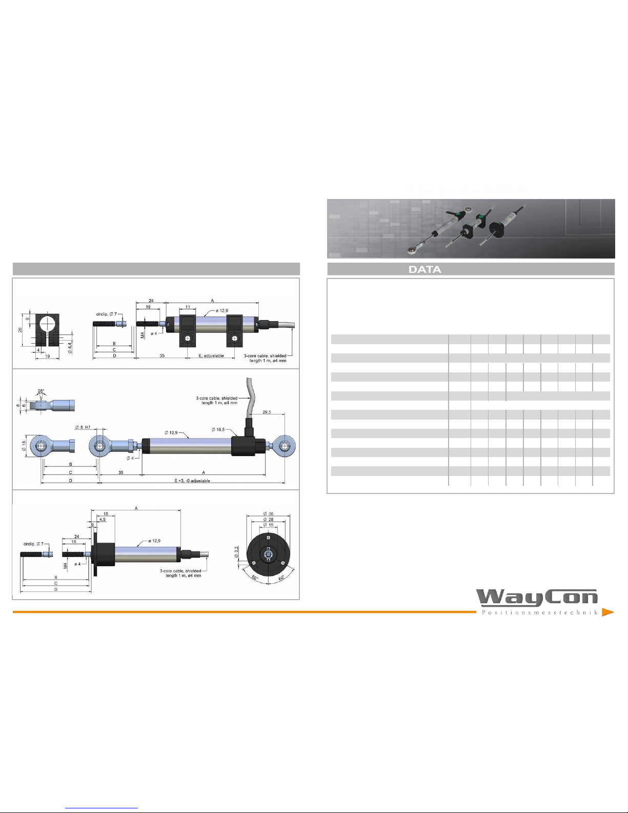
TECHNICAL DRAWING
Useful electrical stroke B: corres ponds to the sensors measurement range
Theoretical electrical stroke C: actual length of the conductive path, that has to be longer than B, in order
to get a valid electrical signal at the s tart and end point of the measurement range.
When c alibrating the transducer, be careful to set the stroke so that the output does not drop below 1%
or rise above 99% of the voltage level.
LZW1-S: installation w ith brackets
LZW1-A: installation with rod end bearings
rod end bearing SND002
(included in delivery)
rod end bearing
SND001
(included in
delivery)
bracket STA074 (2 pieces
included in delivery)
LZW1-F: installation wi th flange
Measurement range [mm] 25 50 75 100 125 150 200 250
Electrical strok e (B) +1/-0 [mm] 25 50 75 100 125 150 200 250
Theoretical electrical s troke (C) ±1 [mm] B + 1
Resistance 1 2 3 4 5 6 8 6
Linearity [±%] 0.2 0.1 0.1 0.1 0.05 0.05 0.05 0.05
Dissipation at 40°C (0 W at 120°C) [W] 0.5 1 1. 5 2 2.5 3 3 3
Maximum applicable voltage [V] 20 40 60
Mechanical stroke (D) [mm] B + 5
Case length (A) LZW1-S [mm] 74.5 99.5 124.5 149.5 174.5 199.5 249.5 299.5
Case length (A) LZW1-A [mm] 102 127 152 177 202 227 277 327
Case length (A) LZW1-F [mm ] 74.5 99.5 124.5 149.5 174.5 199.5 249.5 299.5
Recommended distance between brackets (E) [mm] 42 67 92 117 142 167 217 267
Minimum distance between rod end bearings (E)
[mm] 153 178 203 228 253 278 328 378
Weight LZW1-S [g] 45 55 65 75 85 95 115 135
Weight LZW1-A [g] 70 80 90 100 110 120 140 160
Weight LZW1-F [g] 60 70 80 90 100 110 130 150
[kOhm]
 Loading...