


LLD-500
Manual
Dear user,
Please read this operating manual carefully before starting to operate the LLD-500 laser distance meter. This is
the only way to make sure that you will be able to make full use of the capabilities of your new laser distance
meter, and to prevent any dam-age caused by operating errors.
Editorial deadline: 30.11.2016
Documentation number: 012890-001-98HB-G044-C0
WayCon Positionsmesstechnik GmbH
Mehlbeerenstraße 4
82024 Taufkirchen, Germany
Tel.: +49 89 67 97 13-0
Fax: +49 89 67 97 13-250
E-Mail: info@waycon.de
Internet: www.waycon.biz
Revision Status
Date
Release
Revision
Remarks
06.11.2013
001
001
Series
31.01.2014
001
002
SSI
20.03.2014
001
003
Profibus
25.04.2014
001
004
Baud rate, wiring diagrams new, command PB, error
handling
19.09.2014
001
005
SSI + RS232 wiring diagram, SSI transmission rate
10.12.2015
001
006
Chapter 1.3/3.1/3.3/4.9/
6.3.1/6.3.2/6.4.1/6.4.2/6.4.3/6.4.5/6.4.6/6.4.9/6.4.10/6.4.
11/6.4.12/6.4.15/6.4.16/6.5.1/6.5.2/6.5.3/6.7/ 6.8.1/
6.9/9/10
01.11.2016
002
000
2.2. lasercertification
30.09.2017
30.09.2017
30.09.2017
30.09.2017
CE
No part of this manual may be reproduced in any form (photograph, photocopy, microfilm or any other
procedure) without the prior written permission of WayCon Positionsmesstechnik GmbH, nor may contents be processed, reproduced or distributed using electronic systems. This operating manual was
pro-duced with the appropriate care. No liability will be accepted for damage resulting from the nonob-servance of the information contained in this manual.
We reserve the right to modify the document following technical advancements.

2
Table of contents:
1. Overview ........................................................................................................................................................ 5
1.1 Symbols and references ................................................................................................................................. 5
1.2 Warning signs ................................................................................................................................................ 5
1.3 General information ....................................................................................................................................... 5
2. Safety advice ...................................................................................................................................................... 6
2.1 Basic safety advice ........................................................................................................................................ 6
2.2 Laser class .................................................................................................................................................... 7
2.3 Transport and storage ................................................................................................................................... 7
2.4 Cleaning and maintenance............................................................................................................................ 7
2.5 Service........................................................................................................................................................... 7
3. Intended use ....................................................................................................................................................... 8
3.1 Operating and storage conditions ................................................................................................................. 8
3.2 Improper use and possible error sources ...................................................................................................... 8
3.3 Warning signs and type plates ...................................................................................................................... 9
4. Device description ........................................................................................................................................... 10
4.1 General information ..................................................................................................................................... 10
4.2 Scope of delivery ......................................................................................................................................... 10
4.3 Mechanical installation ................................................................................................................................ 11
4.4 Device cable connector pin assignment ...................................................................................................... 12
4.5 Overview Interfaces ..................................................................................................................................... 13
4.6 Serial Interface RS232 ................................................................................................................................ 13
4.7 Serial interface RS422 ................................................................................................................................. 14
4.8 Serially Interface RS485 .............................................................................................................................. 14
4.9 SSI Synchronous Serial Interface ................................................................................................................ 15
4.10 Profibus-Interface ...................................................................................................................................... 17
4.11 Laser beam image ..................................................................................................................................... 18
5. Installation and commissioning ..................................................................................................................... 18
5.1 Mechanical installation conditions ............................................................................................................... 18
5.2 Commissioning ............................................................................................................................................ 19
5.2.1 Preparatory work prior to installation ................................................................................................... 19
5.2.2 Installation work checklist .................................................................................................................... 19
6. Parameter setup and measuring operation .................................................................................................. 20
6.1 General information ..................................................................................................................................... 20
6.2 Measurement involving moving targets ....................................................................................................... 20
6.3 Identification ................................................................................................................................................ 21
6.3.1 ID recognition ....................................................................................................................................... 21
6.3.2 ID? – Online help ................................................................................................................................. 21
6.4 Status .......................................................................................................................................................... 22
6.4.1 Internal temperature ............................................................................................................................. 22
6.4.2 PA – Parameter setting ........................................................................................................................ 22
6.4.3 PR – Parameter Reset ......................................................................................................................... 23
6.4.4 SA – Average value .............................................................................................................................. 23
6.4.5 MF – Measuring frequency .................................................................................................................. 24

3
6.4.6 MW – Measurement window ................................................................................................................ 24
6.4.7 MUN – Unit of the measured value ...................................................................................................... 25
6.4.8 SF – Scale factor .................................................................................................................................. 25
6.4.9 OF – Offset ........................................................................................................................................... 25
6.4.10 SO-Set Offset ..................................................................................................................................... 26
6.4.11 SD – Data format of the serial interface output.................................................................................. 26
6.4.12 BR – Baudrate .................................................................................................................................... 27
6.4.13 SB – Stop bit of the serial output ....................................................................................................... 28
6.4.14 RS – Serial Port ................................................................................................................................. 28
6.4.15 AS – Autostart .................................................................................................................................... 28
6.4.16 TE - Terminator .................................................................................................................................. 30
6.4.18 SP-Separator for parameters ............................................................................................................. 31
6.4.19 HE – Heating adjustment ................................................................................................................... 31
6.4.20 MCT – Output/ Modification of the operating mode when starting a measurement using the display
...................................................................................................................................................................... 31
6.4.21 PB – Setting the Profibus parameters ................................................................................................. 32
6.4.22 SSA – Profibus slave address ............................................................................................................ 32
6.4.23 SSI – Setting the SSI parameters....................................................................................................... 32
6.4.24 Additional commands ......................................................................................................................... 33
6.5 Operating modes ......................................................................................................................................... 33
6.5.1 DM – Individual distance measurement ............................................................................................... 33
6.5.2 DT – Continuous distance measurement (distance tracking)............................................................... 33
6.5.3 CT – Continuous tracking ..................................................................................................................... 35
2
values for maximum accuracy for the lower and upper limit of measuring range ...... Fehler! Textmarke nicht
definiert.
6.6 Q1/Q2/Q3 – Switching output ...................................................................................................................... 36
6.7 QA – Analog output ..................................................................................................................................... 38
6.8 TRI + TRO Trigger ....................................................................................................................................... 40
6.8.1 Trigger function .................................................................................................................................... 40
6.8.2 TRI – Trigger-Input ............................................................................................................................... 40
6.8.3 TRO – Trigger-output ........................................................................................................................... 41
6.9 Direct controlling of the LLD-500 ................................................................................................................. 42
7. Serial interface and communication software .............................................................................................. 44
7.1 Transmission protocol ................................................................................................................................. 44
7.2 Installation of the communication program ................................................................................................. 44
8. Profibus ............................................................................................................................................................ 46
8.1 ID-Number ................................................................................................................................................... 46
8.2 Connecting conditions ................................................................................................................................. 46
8.3 GSD-File ...................................................................................................................................................... 46
8.4 Slave address .............................................................................................................................................. 47
8.5 Profibus termination .................................................................................................................................... 47
8.6 Baudrate ...................................................................................................................................................... 47
8.7 Length of segment ....................................................................................................................................... 47
8.9 Configuration data ....................................................................................................................................... 48
8.10 Cyclical data exchange – input (slave -> master) ...................................................................................... 49
8.11 Cyclical data exchange – output (master -> slave) .................................................................................... 49

4
8.12 Parameter data .......................................................................................................................................... 50
8.13 Diagnostic data .......................................................................................................................................... 52
8.14 Tips for start-up (Siemens STEP7) ............................................................................................................ 54
8.15 Error display .............................................................................................................................................. 54
8.16 Monitoring .................................................................................................................................................. 54
8.17 Service program SL5.exe .......................................................................................................................... 54
8.17.1 Overview ............................................................................................................................................ 54
8.17.2 Setting a Profibus slave address at the LLD-500 ............................................................................... 56
8.17.3 Parameter-Dialog ............................................................................................................................... 56
8.17.4 Diag Common .................................................................................................................................... 56
8.17.5 Diag Alarm ......................................................................................................................................... 56
8.17.6 Trace .................................................................................................................................................. 56
8.17.7 Log-File .............................................................................................................................................. 57
9. Error processing .............................................................................................................................................. 58
10. Technical Data ................................................................................................................................................ 59

5
1. Overview
1.1 Symbols and references
D Enumeration
Note / important note
Reference (to a text passage or illustration)
1.2 Warning signs
The sign Caution warns against dangers to health which may occur if this advice is not observed
The sign Attention warns against possible damage to the device
The sign Information points to important information.
This sign indicates that special environmental protection guidelines must be observed when disposing of the
device.
1.3 General information
The laser distance meters of the LLD-500 series have been designed for application in industrial facilities.
Within the measuring range of 15 cm to 200 m the sensors work with a high accuracy of up to + 2.1 mm and at
a variably adjustable measuring frequency of maximally 100 Hz.
Due to the excellent optical measuring performance of the LLD the sensors can be used both indoors and outdoors, even in case of a high percentage of constant light. Moreover, they can be used for measuring very hot
surfaces such as glowing steel.
When great distances of more than 50 m need to be measured, the sensor can be used in combination with a
reflector. Simple assembly and standard interfaces enable the quick integration of the device into complex
measuring and control systems.
Data can be displayed and parameters can be set using an internal keypad and display or an external communi-
cation program.

6
2. Safety advice
2.1 Basic safety advice
Please read the safety and operating advice carefully, and observe the advice when operating the LLD-500 laser distance measurement device.
Danger, laser radiation. The LLD-500 must not be opened unauthorized, otherwise laser radiation can be emitted that can cause injuries to the eyes. Please observe all information and
guidelines for operating the laser.
Danger, electric shock
The LLD-500 may only be opened for repair purposes by the manufacturer. If the device is
opened arbitrarily without authorization, all warranty claims will expire.
The operating and storage conditions ( chapter 9) have to be observed. The non- observance
of this advice and the adverse use of the device can lead to injuries of the user or to damage
of the device.
Connectors may not be plugged or unplugged when voltage is applied.
All installation work may only be carried out when no voltage is applied.
The device may only be operated as intended and in faultless condition.
Safety installations must not be rendered ineffective.
Safety and warning signs must not be removed.
Protection degree:
In accordance with the protection degree IP67, the LLD-500 is protected against jet water
and dust, and against short submersion into water.
When operating the device under extreme outdoor environmental conditions, the use of additional weather protection is recommended (e.g. a cover plate with a short distance to the
LLD-500). Rapid temperature changes can lead to humidity entering the device.
If the device is exposed to humidity, the temperature difference between the de- vice and the
environment may be ± 5K maximum.
The device is not shatter-proof. Do not let the device fall onto the ground, and avoid any agitation.
The device may not be used in explosive environments; otherwise there is the danger of
damage to the LLD-500 and the surrounding equipment, and of injuries of the user.

7
2.2 Laser class
Based on the standard EN 60825-1:2014 the LLD-500 is in correspondence with laser class 2.
When looking into the laser beam accidentally and for a short moment, the eye will be protected by
the eyelid closing reflex. The eyelid closing reflex can be affected by pharmaceuticals, alcohol and
other substances.
2.3 Transport and storage
The LLD-500 laser distance meter is delivered in standard packaging. All kinds of transport are permitted. It is recommended to store the unit inside the transport packaging until it is used.
Please observe the storage conditions.
2.4 Cleaning and maintenance
The LLD-500 does not require any maintenance. To ensure trouble-free measurements, the optical surfaces
through which the laser beam exits and enters must be free of deposits. Dust can be removed using an air
brush. In case of dirt that is hard to remove, please contact the manufacturer.
The device must not be cleaned using solvents or mechanical tools. Mechanical or electrical modifications of the device are not permitted.
2.5 Service
In case that repair work is necessary, please send the device to the address below:
WayCon Positionsmesstechnik GmbH
Mehlbeerenstr. 4
82024 Taufkirchen
Deutschland
If you have any questions, please contact us via telephone, fax or e-mail:
Tel.: +49 89 67 97 13-0
Fax: +49 89 67 97 13-250
E-Mail: info@waycon.de
Internet: www.waycon.biz

8
3. Intended use
3.1 Operating and storage conditions
Operating temperature
1
- 10 °C … + 60 °C (special type - 40 °C … + 60 °C)
Storage temperature
- 40 °C … + 70 °C
Humidity
15 % … 90 %, non-condensing
1
Depending on the type of device
Explanation: The values specified as operating temperature descripe the temperature range in which the LLD
can be used according to the specification.
The operating temperature refers to the internal temperature of LLD and could be approx….
10 kelvins above the ambient temperature (see EN 60204-1).
If LLD-500 operates near the upper limit of temperature range (ambient temperature > 40
°C), the probability of measuring errors will be increased.
A permanent operation of LLD-500 at higher temperatures (ambient temperature > 40 °C)
shortens the lifetime of the sensor. For permanent operation of LLD-500 it is recommended not to exceed an operation temperature of 50 °C, which correlates to a maximum
ambient temperature of 40 °C.
3.2 Improper use and possible error sources
• The unit may be used only as prescribed.
• Please do not remove any labels and type plates.
• Repair work must not be performed by the user. In case of questions or doubt, the manufacturer is to
be consulted. For contact data see section 2.5.
• In order to obtain correct measuring values the following advice is to be observed:
1. Measurements against the sun or onto surfaces with low reflectivity in very bright
environments can result in faulty measurements.
2.
Measurements through glass, optical filters, Plexiglas or other translucent materi
als are possible to
a limited extent but can result in measurement errors.

9
3.3 Warning signs and type plates
Laser label
The LLD-500 works with a class 2 laser.
When looking into the laser beam accidentally and for a
short moment, the eye will be protected by the eyelid
closing reflex. The eyelid closing reflex can be affected
by pharmaceuticals, alcohol and drugs.
This device may be used without any additional safety
precautions when the following advice is observed:
► Do not look directly into the laser beam.
► Do not look at the laser beam using optical
instruments.
► Do not point the laser beam at other people.
WayCon Positionsmesstechnik
82024 Taufkirchen
Made in Germany
YOM 2013
SN 130004
Power 10 ... 30VDC, max. 10W
Op.-temp -10°C ... +60°C
IP67
Type plate
The type plate shown is an example. Type and serial number
(SN) may differ from this image.

10
4. Device description
4.1 General information
The LLD-500 distance meter is available in different versions. Types can be selected based on the required interface
and on the temperature conditions at the place of application.
LLD-500 versions designed for an operating temperature of as low as – 40 °C can be used for applications outdoors
or in refrigerated warehouses. The heating element ensures the operating temperatu re of the components and free
optics (no condensation) of the LLD-500.
The required connecting cables are available with straight and angular plug -in connectors. In order to prevent the
direct incidence of extraneous light into the device optics, a light protector is available as well that can be screwed
onto the device. Devices with a cable length of up to 10 m are demonstrably EMC-safe.
4.2 Scope of delivery
The device variants of the LLD-500 and its accessories can be ordered under the following part numbers
Designation
Part no.
Remarks
LLD-500-RS
012890-001-22
RS232/ RS422/ RS485
LLD-500-SSI
012890-002-22
RS232/ RS422/ RS485 + SSI
LLD-500-PROF
012890-003-22
RS232/ RS422/ RS485 + PROFIBUS
LLD-500-SSIPROF
012890-004-22
RS232/ RS422/ RS485 + PROFIBUS + SSI
LLD-500-RS-H
012890-041-22
– 40°C |RS232/ RS422/ RS485
LLD-500-SSI-H
012890-042-22
– 40°C | RS232/ RS422/ RS485 + SSI
LLD-500-PROF-H
012890-043-22
– 40°C | RS232/ RS422/ RS485 + PROFIBUS
LLD-500-SSI-PROF-H
012890-044-22
– 40°C | RS232/ RS422/ RS485 + PROFIBUS + SSI
Accessories
Device cable 2 m
012840-144-24
Device cable 5 m
012840-145-24
Device cable 10 m
012840-146-24
Device cable 2 m, angular
012890-110-24
Device cable 5 m, angular
012890-111-24
Device cable 10 m, angular
012890-112-24
SSI-cable 2 m
012890-101-24
PB in/out cable, 5 m
012840-170-24
PB in cable jack, 5 m
012840-165-24
PB in cable jack, 10 m
012840-166-24
PB out cable plug, 5 m
012840-160-24
PB out cable plug, 10 m
012840-161-24
PB female protective cap
94366
Female connector
PB male protective cap
94363
Male connector
PB terminating resistor M12
94145
PB 3-pin female connector
94136
PB 3-pin male connector
94133
LLD-500 light protector
012890-250-12
Reflective tape Oralite 5200,
1000x1000
012890-002-28
1 m x 1 m measurements from as low as 50 m
Reflective tape 3M 3279 special
012890-003-28
300 mm x 300 mm measurements from as low as
0.5 m

11
4.3 Mechanical installation
Der The LLD-500 can be screwed on using 3 (underside) or 2 M6 fastening screws respectively (length to be
chosen depending on the counter piece). 3 M6 fastening screws plus washers and washer springs are included
in the scope of delivery.
Figure 1: LLD-500 dimensions
The zero point for measurement is identical with the housing front face.

12
4.4 Device cable connector pin assignment
PIN
Colorcode
RS232
RS422
RS485
Description
A white
RxD
Rx+
n.c.
RS232 Receiver data/ RS422 Receiver data +
B brown
n.c.
Rx-
n.c.
RS422 Receiver data -
C green
TRIG
TRIG TRIG
Trigger input / output
D yellow
QA
QA
QA
Analog output (3 mA … 21 mA)
E grey
n.c.
Tx- B
RS232 Transmitter data/ RS422 Transmitter data -
F pink
TxD
Tx+ A
RS422 Transmitter data +
G blue
Q3
Q3
Q3
Switching output Q3
H red VCC
VCC VCC
Supply voltage 10 …30 VDC
J black
GND
power
GND
power
GND
power
Ground supply voltage
K violet Q2
Q2
Q2
Switching output Q2
L grey / pink
GND
signal
GND
signal
GND
signal
Ground output signal, analog
M red / blue
Q1
Q1
Q1
Switching output Q1
Figure 2: Cable jack pin assignment
The shield of the device cable is to be connected to the shield connector of the equipment, e.g. PLC.
► Inverse polarity protection is provided.
► Overvoltage protection is provided up to a maximum of 30 VDC.
► GND
signal
and GND
power
are internal combined without galvanic isolation.
Open, unused cable wires must be insulated.

13
4.5 Overview Interfaces
Figure 3: LLD-500 all interfaces
If LLD-500 types with Profibus interface should be used via serial interface only, the Profibus parameter
PB must be disabled with command PB 0.
4.6 Serial Interface RS232
Figure 4: Wiring of serial interface RS232
The serial interface RS232 can be used for
► Measured data transmission
►
LLD-500 parameterization

14
4.7 Serial interface RS422
Figure 5: Wiring of serial interface RS422
►
Wiring D-SUB9 is not standardized, please check your system.
4.8 Serially Interface RS485
Figure 6: Wiring of serial interface RS485
►
Wiring D-SUB9 is not standardized, please check your system.

15
4.9 SSI Synchronous Serial Interface
SSI will be parameterized via serial interface or the internal display of LLD-500
SSI data interface is optional for LLD-500 (please see the types and order numbers in chapter 4.2). At the
request of a SSI clock LLD-500 starts the output of measuring values and sends the data bit by bit from the shift
register of LLD-500 (Slave) to an external controller (Master).
It could be used all measuring modes of LLD-500. The active measurement mode will be set via serial interface
or Profibus or internal display.
Setup via serial interface → see chapter 6.4.22 SSI und 6.4.16 SE
Setup via internal display → Parameters / BUS / SSI / SSI mode
SSI works independent of Profibus interface.
Transmission rate 150 kHz … 300 kHz
Break duration minimum 25 µs (between 2 bit sequences)
Data length 24 bit or 25 bit (programmable)
Format binary code or gray code (programmable)
Bit string:
1)
Data length 24 bits → bit 23 – 0 = data string
Bit
23
22 – 1 0
MSB
LSB
2)
Data length 25 bits → bit 24 = error bit , bit 23 – 0 = Data string
Bit
24
23 – 1 0
MSB=error bit
LSB
The inputs (CLOCK) are galvanic isolated, the potential separation is realized up to 500V.
To ensure undisturbed data transfer paired twisted wires are required.
Clock rate
Cable length
< 300 kHz
< 100 m
< 250 kHz
< 150 m
< 200 kHz
< 200 m

16
Figure 7: Wiring of SSI and cable jack pin
The measuring mode will be defined with command AUTOSTART AS.
Please note that by using of parameter measurement window MW (chapter 6.4.6) and / or offset OF (chapter
6.4.9) the distance output value has to be in the positive range (distance value > 0). Otherwise the SSI output
will be 000000.
► SSI Input (Clock+/ Clock-) and system power are galvanic isolated.

17
4.10 Profibus-Interface
► Please see detailed Profibus information in chapter 8
► Profibus INPUT and OUTPUT are galvanic isolated.
Figure 8: Wiring of Profibus Interface

18
4.11 Laser beam image
The laser beam of the LLD-500 has a divergence of 0.13 mrad x 0.17 mrad (width x height). The diameter of
the laser spot on the exit lens measures 4 mm.
The table below shows the size of the laser spot in dependence on the distance. The laser spot has an elliptical shape.
Distance
Laser spot width
Laser spot height
1 m
5 mm
5 mm
5 m
3 mm
3 mm
10 m
4 mm
5 mm
50 m
6 mm
7 mm
100 m
26 mm
34 mm
200 m
52 mm
68 mm
The above mentioned laser spot holds approx. 50 % of the entire laser energy. An aura with less energy
forms around that spot.
5. Installation and commissioning
5.1 Mechanical installation conditions
There are two different ways to install the LLD-500 laser distance meter. 3 M6 socket cap screws are included in
the scope of delivery.
1. Fastening through one of the side faces
Two M6 screws + washer spring + washer
2. Fastening through the housing bottom
Three M6 screws + washer spring + washer
3. Cable connections
In order to ensure variability in the application of the device, connecting cables with straight or angular connectors are available (also see chapter 4.2).
The cables are not included in the scope of delivery. Please order them as required.
4. Attaching the light protector (optional)
An optional light protector is available for application in very bright environments. Part number: 012890-250-12
The light protector is attached to the front face (laser beam emission point) using three M3x6 screws.
The screws are included in the scope of delivery of the light protector.
When the device is used outdoors under extreme environmental conditions, an additional
weather protector (e.g. cover plate in a small distance to the LLD) is recommended. Other-
wise, moisture may enter the device despite the IP67 due to rapid temperature changes.

19
5.2 Commissioning
5.2.1 Preparatory work prior to installation
► Remove the packaging of the LLD-500.
► Check the delivery for completeness.
► Examine the device and the accessories for damage.
► Examine the connections and cables for damage.
5.2.2 Installation work checklist
The following table suggests a commissioning procedure for the LLD-500, without claiming to be exhaustive.
The user is responsible for the application-specific cabling and for the parameterization of the Profibus
(optional), particularly of the slave address. Thus, the latter are taken as a given.
Where the LLD-500 is taken into operation for the first time, we recommend carrying through the configuration
steps at a laboratory or office.
The device can be configured using either the display or a communication program. For example, the program
HyperTerminal (included in Win32 operating systems) or any other communication program can be used.
In order to parameterize the device using a communication program, the LLD-500 must be connected to supply
voltage and a PC (also see Fig. 2 in chapter 4.4).
SSI and/or Profibus need to be set separately.
No.
Work step
1 Unpack the LLD-500, check it for damage.
2 Mount the LLD-500 at the target location (with 2 screws through the side face or 3 screws through
the bottom) --> see 5.1.
Roughly direct it at the target surface.
3 Plug and firmly screw on the interface cable in the de-energized condition.
4 Connect and firmly screw on the Profibus and SSI connections (optional).
5 Wire the open cable end. Energize. Green status LED must light up.
6 As soon as STATUS LED is green, the red laser beam will be visible. Precondition: AS DT (default
value). Mechanical fine adjustment can be executed.
7 Parameterize the LLD-500 via the menu navigation on the display. Alternatively parameterize the
device using a terminal program.
8 Activate the distance measurement mode (e.g. DT).
9 Start the distance measurement (laser is switched on). Measurement output and Status- LED must
be checked. Stop the distance measurement mode.
Alternative: Start measurement via Profibus.
The SSI measurement mode is to be defined in the AUTOSTART AS command.
10
Final visual check

20
6. Parameter setup and measuring operation
6.1 General information
The LLD-500 is parameterized using the serial interface or the display. Precondition for programming via serial
interface is a connec-tion provided by a terminal program (e.g. HyperTerminal --> see chapter 7).
The set parameters are stored in an EEPROM.
The last entered data will be available upon restarting.
►
Retrieval of parameters
Input PARAMETER <ENTER> <ENTER> = CR = (0x0D)
►
Setting of parameters
Input PARAMETER VARIABLE <ENTER>
The variables are described with the individual parameters.
Several variables are separated by spaces (0x20).
► Starting a measurement (operating mode) Input COMMAND<ENTER>
► Starting a measurement (operating modes) Input COMMAND <ENTER>
► Stopping a measurement <ESC> <ESC> = (0x1B)
► Distances are always entered in 0.1 mm (100 µm).
The scale factor SF has no influence on the input parameters.
Example: Input
3.20 m = 32000
The output values shown in the manual are examples. They may vary depending on the settings and environ-
mental conditions.
Whenever an incorrect or incomplete command is entered, the following responses are shown:
The input does not contain any parameter or command.
e.g.: HELLO<ENTER>
Parameter with current value Entry of a parameter with incorrect figure/ parameterization
e.g.:
Input: SAxxx<ENTER>
Output: SA 10 (where SA = 10 prior to input)
6.2 Measurement involving moving targets
Where measurements involve a moving object or the LLD-500 is moved during measuring, this will have an im-
pact on the accuracy of the measured value.
This must be observed particularly when calculating average values (parameter SA).
Measurement jumps and/or considerable changes in the reflectivity of the target surface can prolong the
measurement period.
In case of a fixed measuring frequency (parameter MF), this may result in no measured value being generated
within the predefined time. A warning or error message will be displayed instead.

21
6.3 Identification
6.3.1 ID recognition
When entering the command ID, the LLD-500 will respond by displaying the manufacturer’s data in the following
order: Device type, serial number, manufacturer’s part number, firmware version, time stamp.
Example: LLD-500 130004 012890-001-22 V5.14.0422 13-10-02.13:59
6.3.2 ID? – Online help
By entering the command ID, the user will obtain an overview of all available operations and parameters
described in the following sections.
Response:
Command List: Command must start with correct beginning, e.g.: "DM2" = "DM 2".
(%u) declares the option of adding a positive integer to change the parameter.
(%d) declares the option of adding an integer to change the parameter.
(%f) declares the option of adding a floating-point number to change the parameter.
(%s) declares the option of adding a string (e.g. "cm" in case of MUN) to change the parameter.
(%b) declares the option of adding a boolean value (0 = false, or 1 = true) to change the parameter.
**Identifications**
ID? Prints this help.
ID Prints the firmware ID.
**Status/Parameters**
TP Prints the temperature of the device.
PA Prints all parameters.
PR Resets the parameters to firmware defaults.
SA (%u) Prints/Changes average. Co-domain: [1, 50].
MF (%f) Prints/Changes measurement frequency. Co-domain: [0.0, 100.0], (0 == auto).
MW (%u %u) Prints/Changes the expected ranged for measurements in 'mm / 10'.
MUN (%s) Prints/Changes the unit of the measurements. Co-domain:
{mm, cm, dm, m, in/8, in/16, in, ft, yd}
OF (%d) Prints/Changes the offset in 'mm / 10'. Co-domain: [-5000000, 5000000].
SD (%u %b %b %b) Prints/Changes the output format.
Q1 (%d %u %d %b) Prints/Changes the parameterization of switching output Q1.
Q2 (%d %u %d %b) Prints/Changes the parameterization of switching output Q2.
Q3 (%d %u %d %b) Prints/Changes the parameterization of switching output Q3.
QA (%u %u) Prints/Changes the parameterization of the analog switching output QA.
TRI (%u %u) Prints/Changes the parameterization of the input trigger TRI.
TRO (%u %u) Prints/Changes the parameterization of the output trigger TRO.
BR (%u) Prints/Changes the baudrate of the serial port. Co-domain: {600, 1200, 2400, 4800,
9600, 14400, 19200, 28800, 38400, 56000, 57600, 115200, 128000, 230400, 256000}.
SB (%f) Prints/Changes the stop bits of the serial port. Co-domain: {0.5, 1.0, 1.5, 2.0}.
RS (%u) Prints/Changes the mode of the serial port. Co-domain: {232, 485, 422}.
AS (%u) Prints/Changes the autostart commands. Co-domain: {1 … 12}.
TE (%u) Prints/Changes the terminator. Co-domain: {1 … 10}.
SE (%u) Prints/Changes the behavior on errors. Co-domain: {0 ... 2}.
SP (%u) Prints/Changes the character that separates the values (e.g. distance and temperature).
Codomain: {1 ... 5}.
SF (%f) Prints/Changes the scaling factor. To use [MUN] set "SF 0". Co-domain: [(+/-) 0.001, (+/-
) 10.000].
MCT (%b) Prints/Changes the tracking mode, started from the menu. Co-domain:
{0 == standard, 1 == continuous}.
DF Turns off the OLED display.
DN Turns on the OLED display.
Query:

22
**Operation Mode**
DR Restarts the device (does not reset parameters).
LF Deactivates laser diode.
DM Starts single (precise) measurement.
DT Activates/Deactivates tracking mode.
CT Activates/Deactivates continuous tracking mode.
SDT Deactivates tracking modes.
LN Activates laser diode.
6.4 Status
6.4.1 Internal temperature
Output of the internal device temperature in °C. The internal temperature is about 10 kelvins higher than the
ambient temperature. When the specified temperature range is exceeded or fallen short of, the warning w1904
or w1905 will be generated cyclically. Measurements will not be possible until the temperature has returned to a
point within the specified range.
Response (example): 26 °C
Please see the notes in chapter 3.1.
6.4.2 PA – Parameter setting
Output of a parameter list with the current settings
Query:
PA
Output:
Baudrate of serial port [BR]: 115200
Stop bits of serial port [SB]: 1
Serial port mode (RS232/422/485) [RS]: 232
Average [SA]: 10
Measurement frequency [MF]: 50.0
Minimum distance from target [MW]: -5000000
Maximum distance from target [MW]: 5000000
Offset in 'mm / 10' [OF]: 0
Parametrization of switching output Q1 [Q1]: 0, 1000000, 2500, 0
Parametrization of switching output Q2 [Q2]: 0, 1000000, 2500, 0
Parametrization of switching output Q3 [Q3]: 0, 1000000, 2500, 0
Parametrization of the analog switching output QA [QA]: 0, 1000000
Unit for the distances [MUN]: mm
Trigger (input) [TRI]: 0, 0
Trigger (output) [TRO]: 0, 0
Autostart commands [AS]: DT
Output format [SD]: 0 0 0 0
Terminator [TE]: 0x0D0A
Scale factor [SF]: 0.000
Error mode [SE]: 0
Separator [SP]: 0x2C
Standard tracking mode from menu [MCT]: 0

23
6.4.3 PR – Parameter Reset
Resetting of all parameters to factory settings (default values).
The following parameters are not reset by entering PR:
BR Baudrate
RS Serial port
SB Stop bits
SSI SSI interface parameters
PB Profibus interface parameters setting parameters for serial interface
Query
PR
Output:
Parameters set to firmware defaults.
Baudrate of serial port [BR]: 115200
Stop bits of serial port [SB]: 1
Serial port mode (RS232/422/485) [RS]: 232
Average [SA]: 1
Measurement frequency [MF]: 0.0
Minimum distance from target [MW]: 5000000
Maximum distance from target [MW]: 5000000
Offset in 'mm / 10' [OF]: 0
Parametrization of switching output Q1 [Q1]: 0, 1000000, 2500, 0
Parametrization of switching output Q2 [Q2]: 0, 1000000, 2500, 0
Parametrization of switching output Q3 [Q3]: 0, 1000000, 2500, 0
Parametrization of the analog switching output QA [QA]: 0, 1000000
Unit for the distances [MUN]: mm
Trigger (input) [TRI]: 0, 0
Trigger (output) [TRO]: 0, 0
Autostart commands [AS]: DT
Output format [SD]: 0 0 0 0
Terminator [TE]: 0x0D0A
Scale factor [SF]: 0.000
Error mode [SE]: 0
Separator [SP]: 0x2C
Standard tracking mode from menu [MCT]: 0
6.4.4 SA – Average value
SA parameterizes the number x of the individual measured values to be averaged for measured value output.
SA directly correlates with the measuring frequency MF. SA and MF determine the output frequency for the
measured values.
Query:
SA
Set:
SAx
Range of parameter x:
1…50; resolution: 1
Standard:
1
Output: Average [SA]: 1
The spread of the measured values can be reduced by determining average values.
σ1
σ
SA
=
σ
SA
Spread after average determination including several distance measurements
σ
1
Spread of individual measured values (+ 1 mm)
SA
Average value
Example values of measurements involving a target with 80% reflectivity and a maximum distance of 30 m.

24
Measuring frequency MF (Hz)
Average value SA
Output frequency (Hz)
Spread in mm
20 1
20
+ 1,0
20
10 2
+ 0,3
6.4.5 MF – Measuring frequency
MF parameterizes the number x of the measured value outputs per second. When a value x outside of the
measurement range is entered, the lowest or highest permissible MF value will automatically be set.
Entered value < x → MF 0.0
Entered value > x → MF 100.0
MF 0 = Automatic measurement. The output frequency ranges between 0.3 Hz and 10 Hz in most cases.
Essential factors concerning the measurement period are, among others, the reflectivity of the target surface
and the environmental conditions (e.g. light, fog, and rain).
Query:
MF
Set:
MFx
range of parameter x:
0.0 …100.0 (Hz), resolution: 0.1
Standard:
0
Output: Measurement frequency [MF]: 0.0
The measuring period will be longer when an average value SA ≠ 1 is set!
6.4.6 MW – Measurement window
Parameterizes the scope of a measurement window by start x and end y. Only measured values
within the measurement window will be put out.
For example, the measurement window can be used to:
► Eliminate interfering objects before or behind a measurement range
► Define a measurement range
If there is no target object within the defined measurement window, an error message will be gener-
ated cyclically:
► e1207 A target before or behind the measurement window is recognized
► e1203 Target with unsuitable reflectivity
Query:
MW
Set:
MWx y
Range of parameter x:
Resolution: 0.1 mm
Range of parameter y:
Resolution: 0.1 mm
Standard:
-5000000 5000000
Output:
Minimum distance from target [MW]: -5000000 (500 m)
Maximum distance from target [MW]: 5000000 (500 m)
The LLD-500 does not check the set measurement window for plausibility. The user is responsible for correct
parameterization!

25
6.4.7 MUN – Unit of the measured value
MUNx enables the definition of a unit for the output value. It is shown together with the measured value. In
order to use MUN, SF 0 must be set.
Query:
MUN
Set:
MUNx
Range of parameter x:
mm, cm, dm, m, in/8, in/16, in, ft, yd
Standard:
mm
Output: Unit for the distances [MUN]: mm
6.4.8 SF – Scale factor
SFx defines a factor by which the output value is multiplied.
Query:
SF
Set:
SFx
Range of parameter x:
-10.000 …. 10.000
Standard:
0
Output: Scale factor [SF]: 0.000
At SF ≠ 0 the parameter MUN is ineffective.
At SF = 0 the unit defined by MUN becomes effective.
Example of the data output:
SF 0 1 2 10
Distance 1,23 m
001230.0 mm
001230.0
002460.0
00012300
6.4.9 OF – Offset
OF parameterizes a user-specific offset x that is added to the measured value. It is entered in 0.1 mm
Query:
OF
Set:
OFx
Range of parameter x:
-5000000 ….5000000
Standard:
0
Output: Offset in 0,1 mm [OF]: 0
The LLD does not check the set offset for plausibility. The user is responsible for correct parameterization!
The offset can be set by a measurement: command SO (see chapter 6.4.10)

26
6.4.10 SO-Set Offset
With the parameter SO a single distance measurement is carried out and set a – OF (negative offset) SO can
only be executed in this way, it is not a parameter in the strict sense. SO is used for the zero-adjustment of
applications, systems, processes.
Input: SO
Output (for example): Offset in 'mm / 10' [SO]: -21091
6.4.11 SD – Data format of the serial interface output
SD parameterizes the output format and the possible output values. The following outputs are possible:
► Distance
► Signal quality
► Temperature
► Switching outputs (active/ inactive)
Query:
SD
Set:
SDw x y z
Range of parameter w:
0…5
Range of parameter x, y, z:
0 or 1
Standard:
0 0 0 0
Output: [SD]: 0 0 0 0
Separator in correspondence with parameter TE
Parameter
w
Output format
Separators
between the
values
Unit of
measure
(SF 0 + MUN x)
Example
(SF 0 + MUN mm)
0 Decimal
1 separator
Unit
d002 925.4 mm = 2925.4 mm
1 Decimal
None
None
d002925.4 = 2925.4 mm
2
Hexadecimal
(floating point
format
IEEE-754)
None
None
h4536E9EC = 2926.6 mm
3 hexadecimal
None
None
h000B6E = 2926 mm
4 Binary
None
None
0x80 0x01 0x64 0x46 =
2925.4 mm
5
SSI and switching
outputs only
None
None
SSI: Distance value in 0.1 mm
Switching output: 0 or 1
Parameter
Value
Signal quality
Temperature
Switching outputs
x 0 Off
x 1 On
Y 0
Off
Y 1
On
Z 0
Off
Z 1
On

27
Binary format SD – Binary format:
Distance:
4 Byte, MSB = Bit 31
MSB of Byte 3 always 1
MSB of Byte 2, 1 and 0 always 0
Measurement data of each Byte = Bit 6 … Bit 0
Coding: Two´s complement
Signal:
2 Byte
MSB = Bit 15
MSB of Byte 1 and 0 always 0
Measurement data of each Byte = Bit 6 … Bit 0
No sign bit
Maximum value: 16383 (14 Bit data)
Temperature:
2 Byte
MSB = Bit 15
Sign bit = Bit 14
MSB of Byte 1 and 0 always 0
Measurement data of each Byte = Bit 6 … Bit 0
Binary format of switching outputs Q1, Q2, and Q3
1 Byte
MSB = Bit 7 (ist immer 0)
Q1 = Bit 2
Q2 = Bit 1
Q3 = Bit 0
1 = switching output on (active)
0 = switching output off
Bit 7 6 5 4 3 2 1 0 0 0 0 0 0 1 0
1
MSB
Q1 Q2 Q3
= 0
on off on
For parameterizing of switching outputs see chapter 6.6
6.4.12 BR – Baudrate
BR enables the adjustment of the serial baud rate x.
As soon as a new baud rate is set, the device will start communicating with the new baud rate.
BR will not be modified upon a parameter reset via PR.
Query:
BR
Set:
BRx
Range of parameter x:
1200,2400,4800,9600,14400,19200,28800,38400,56000,
57600,115200,128000,230400,256000
Standard:
115200 baud/ 8 data bits /1 stop bit / no parity
Prior to setting a high baud rate of > 115200 baud, make sure that the subsequent
system is capable of processing that baudrate.
If the baud rate of LLD-500 does not match with the baud rate of the communication
program the baud rate of LLD-500 can be changed via LLD-500 display.

28
Output: Baudrate of serial port [BR]: 115200
6.4.13 SB – Stop bit of the serial output
Sets the parameter of the stop bit for serial data transmission.
Query:
SB
Set:
SBx
Range of parameter x:
0.5 / 1.0/ 1.5/ 2.0
Standard:
1.0
Output: Stop bits of serial port [SB]: 1
6.4.14 RS – Serial Port
Selection of the serial interface to be used for communication
Query:
RS
Set:
RSx
Range of parameter x:
232/ 422/ 485
Standard:
232
Output: Serial port mode (RS232/422/485) [RS]: 232
6.4.15 AS – Autostart
The autostart function defines the behavior of the LLD-500 after a cold boot.
After the connection to the supply voltage and the internal start-up routine the LLD-500 will automatically execute the command and send the data to the available outputs.
A figure from the table below must be entered. The display / output shows the command.
Query:
AS
Set:
ASx
Range of parameter x:
1 … 24 (see table below)
Standard:
5
Depending on the measurement mode used, it takes max. 6 sec from applying the supply voltage to the point
where the first measured value is put out.
Output: Autostart commands [AS]: DT
Parameter x see table below
If RS is set to a wrong interface, communication will be impossible!
The setting must be adjusted via the device display afterwards:
Parameters --> BUS --> UART --> RS-232/422/485

29
Value x
Command
Meaning
1
ID
Output of device identification
2
ID?
Output of command list
3
TP
Output of internal device temperature
4
DM
Start of individual measurement
5
DT
Start of continuous measurement
6
CT
Start of quick continuous measurement
7
DF
Display is deactivated
8
DF ID
Display is deactivated + output of device identification
9
DF TP
Display is deactivated + output of internal device temperature
10
DF DM
Display is deactivated + start of individual measurement
11
DF DT
Display is deactivated + start of continuous measurement
12
DF CT
Display is deactivated + start of uninterrupted continuous measurement
LLD-500 types with heating only (temperature range -40 °C … +60 °C)
Value x
Command
Meaning
13
SH
Heating is deactivated
14
SH ID
Heating is deactivated + output of device identification
15
SH TP
Heating is deactivated + output of internal device temperature
16
SH DM
Heating is deactivated + start of individual measurement
17
SH DT
Heating is deactivated + start of continuous measurement
18
SH CT
Heating is deactivated + start of uninterrupted continuous measurement
19
SH DF
Heating is deactivated + display is deactivated
20
SH DF ID
Heating is deactivated + display is deactivated + output of identification
21
SH DF TP
Heating is deactivated + display is deactivated + output of internal device temperature
22
SH DF DM
Heating is deactivated + display is deactivated + start of individual measurement
23
SH DF DT
Heating is deactivated + display is deactivated + start of continuous measurement
24
SH DF CT
Heating is deactivated + display is deactivated +
start of uninterrupted continuous measurement

30
6.4.16 TE - Terminator
TE is used to set the terminator for the output of measured values in the ASCII format (also see command
SD).
Query:
TE
Set:
TEnn
Range of parameter nn:
1 … 10
Standard:
1
Example:
Input: TE 1
Output: Terminator (TE): 0x0D0A
Value selection:
nn
ASCII
Meaning
1
0x0D 0x0A
CR LF
2
0x0D
CR
3
0x0A
LF 4 0x02
STX
5
0x03
ETX
6
0x09
Htab (Tabulator)
7
0x20
Space
8
0x2C
Single Quote
9
0x3A
Colon
10
0x3B
Semicolon
When an invalid character is entered, it will not be set. The current separator will be kept instead.
6.4.17 SE – Error Mode
Parameterizes the behavior x of switching outputs Q1, Q2, Q3 and of the analog output QA in case of faulty
measurements as well was the condition upon execution of an individual distance measurement
Query:
SE
Set:
SEx
Range of parameter x:
0, 1oder 2
Standard:
1
x
Q1, Q2, Q3
QA
SSI
z = 0
z = 1
24 bit
25 bit
0
Last value
Last value
Last value
Last value
MSB High
1
High
Low
3 mA
000000
MSB High
2
Low
High
21 mA
999999
MSB High
Low: U < 1 V
High: U = operating voltage – 1 V
The LLD-500 does not check the set error mode for plausibility!

31
6.4.18 SP-Separator for parameters
Output values are separated by the character SP.
Query:
SP
Set:
SPx
Range of parameter x:
1 … 5
Standard:
1
Output: Separator [SP]: 0x2C
Value x Symbol
ASCII
1 Comma
0x2C
2 Semicolon
0x3B
3 Space
0x20
4 Slash
0x2F
5 Tabulator
0x09
6.4.19 HE – Heating adjustment
The parameter HE defines the switching thresholds for switching the heating element on and off. The command
is enabled only where the device is actually equipped with a heating element.
Query:
HE
Set:
HEx y
Range of parameter x: Switching on heating
-40 … 40 (integer)
Range of parameter y: Switching off heating
-40 … 40 (integer)
Standard:
HE4 10
For switching the heating on or off, the internal measured temperature is compared to the set parameters.
Internal temperature < x (HeatON) -> Heating is switched on.
Internal temperature > y (HeatOFF) -> Heating is switched off.
Please observe the following when setting the parametrization: x (HeatON) <= y (HeatOFF).
6.4.20 MCT – Output/ Modification of the operating mode when starting a
measurement using the display
When starting a continuous measurement using the integrated display, you need to define if the LLD-500 should
measure based on the operating mode DT or CT. The operating mode is selected via the command MCT. When
starting a measurement using the display, the predefined operating mode will be applied as a rule. When a
measurement is started using a communication program or PLC, the command DT or CT will determine the type
of measurement.
Query:
MCT
Set:
MCTx
Range of parameter x:
0 (DT), 1 (CT)
Standard:
0

32
6.4.21 PB – Setting the Profibus parameters
PB parameterizes the availability of Profibus interface.
Query:
PB
Set:
PBx
Range of parameter x:
0 (disabled), 1 (enabled)
Standard:
0
Output: Profibus mode [PB]: 0
For LLD-types with Profibus interface the default value is PB1 (Profibus enabled).
If LLD types with Profibus interface should be used via serial interface only, the Profibus parameter
PB must be disabled with command PB 0.
6.4.22 SSA – Profibus slave address
With parameter SSA the Profibus slave address can be set. It could be set via LLD-500 keys or via service program SL5.exe too.
Query:
SSA
Set:
SSAx
Range of parameter x:
0 … 126
Standard:
4
Output: Profibus slave address [SSA]: 4
6.4.23 SSI – Setting the SSI parameters
SSI defines the Synchronous Serial Interface (see chapter 4.9)
Query:
SSI
Set:
SSIx
Range of parameter x:
0… 4 (see list below)
Standard:
0
Value
Description
0
SSI out (disabled)
1
SSI active / 24 bit / binary
2
SSI active/ 24 bit / gray
3
SSI active/ 25 bit / binary / MSB = Error bit
4
SSI active/ 25 bit / gray / MSB = Error bit
Output: SSI mode (SSI): 0

33
6.4.24 Additional commands
Command
Description
DF
Switches off the display (OLED)
DN
Switches on the display
LF
Switches off the laser diode
LN
Switches on the laser diode
SDT or ESC-Taste
Deactivates the continuous measurement mode
SH
Switches off the heating until restart (available only in devices that are equipped with
a heating element)
TP
Output of device temperature
DR
Executes a restart (does not reset the parameters; no PR!)
6.5 Operating modes
6.5.1 DM – Individual distance measurement
The LLD-500 will perform exactly one measurement and then wait for new instructions. The duration of the
measurement depends on the number of preset measuring values SA and the preset measuring frequency MF.
Input: DM
Typical parameter settings
MF0, SA1, DM
Execute single measurement, allowing for a sufficient period of time as needed to determine the distance to a
static (during the measurement) target object.
MFx, SA1, DM
Execute single measurement, allowing for a period of time of maximally 1 / x seconds to reliably determine the
distance to a static (during the measurement) target object.
6.5.2 DT – Continuous distance measurement (distance tracking)
The LLD performs a continuous measurement. The measurement can be interrupted by a command:
Display STOP
RS232/422/485 Escape = 0x1B
RS232/422/485 command SDT = 0x53 0x44 0x54
The output frequency of the measured values depends on the selected parameters MF and SA.
The DT mode works with high measuring stability in the collection of the measured values, even in case of
beam interruptions and discontinuous motion sequences of the target.
Input: DT
Full measurement (new adjustment of frequencies to define the unambiguous range) will be
forced after beam interruptions.

34
Example response (setting SD1 1 1 0, MUNm): d002.0305, 02736, and 00029
Output format
=
decimal (d)
Distance
=
2,0305 m
Signal quality
=
2736
Temperature
=
29 °C
Remarks:
In case of poor target reflectivity, it cannot be guaranteed at 100 % that the respective measurement will be
completed within a period of time of 0.01 s (100 Hz). Thus, a warning will be generated. --> w1910. The output
frequency will remain constant.
The frequency of warnings and error messages will increase if MF > 20 Hz. In addition an output of wrong distance values could be happen with bare probability. For optimal results the recommendation is to set MF to 20
Hz or lower in mode DT.
There are the following alternatives:
1) A variable output frequency can be selected for surfaces with low reflectivity. The LLD will keep measuring
until a representative distance value can be determined. Normally, the measuring period ranges between 0.01
and 3 seconds (no average determination).
2) Where a measured value output of 100 Hz is not needed, a lower measuring frequency can be set via the
parameter MF. While this parameter influences the output frequency, it has no impact on the internal measuring
frequency. The output frequency can also be reduced by using the average determination function. For example, if an average determination covering 5 measured values (SA 5) includes a warning, only 4 measured values
will be used for average determination. Where there is only one measured value, there will be one output. The
output of warnings is avoided.
The table below shows exemplary the ranges and accuracies in relation to the target surface for outdoor applications. The conditions for the measurements were environmental temperature of +25°C and ambient light
around the target of 1.2 kLux.
The measuring range in an application depends on a large number of factors, e.g. target reflectivity, stray light,
output frequency and other environmental conditions.
Before integration of LLD in a whole system special tests are necessary, to get optimal application results.
Operation Mode DT
Target
Measuring
frequency
Measuring range1
Maximum accuracy
Repealibility
(Standard deviation)
white, matt, reflectivity approx. 80 %
variable
15 cm … 100 m
+ 2,5 mm
+ 1 mm
20 Hz
15 cm … 40 m
+ 2,1 mm
+ 0.7 mm
black, matt, reflectivity approx. 6 %
variable
20 cm … 40 m
+ 2,7 mm
+ 1 mm
20 Hz
20 cm … 16 m
+ 2,7 mm
+ 2.5 mm
Reflective tape 3M 3279 special
variable
15 cm … 100 m
+ 2,1 mm
+ 1 mm
20 Hz
15 cm … 100 m
+ 2,1 mm
+ 1 mm
Reflective tape Oralite 52002
variable
50 m … 200 m
+ 2,1 mm
+ 0.8 mm
20 Hz
50 m … 200 m
+ 2,1 mm
+ 0.6 mm
1in consideration of parameterization in accordance with chapter 6.4.9 and 6.4.10
Measurements on targets with low reflectivity may cause error messages.
If the output frequency is over 20 Hz the fault rate will increase significantly.
w1910
Generating a measured value within the predefined period of time was impossible
(laser searches for suitable parameterization after distance jump/surface change).
MF too high.
e1201/e1203
No laser reflex received (unsuitable / poorly reflecting surface). Reduce the value
of the measuring frequency MF.

35
e1206
Target surface too bright or ambient light too intensive.
e1207
Distance is outside of the measurement window MW.
6.5.3 CT – Continuous tracking
The LLD-500 performs an uninterrupted continuous measurement, adjusting the laser parameters (unambiguous ranges) in relation to the target only every 6 seconds or when an obvious distance measurement error has
occurred. The measuring accuracy for frequencies > 20 Hz is higher in the mode CT as in the operation mode
DT.
Areas of application:
► Scanning of static targets.
► Quick measurements on hot surfaces.
► Tracking of continuously quickly moving targets (e.g. crab [crane], vehicle)
The tables below show the ranges and accuracies in relation to the target surface for outdoor applications. The
conditions for the measurements were environmental temperature of +25°C and ambient light around the target
of 1.2 kLux.
The measuring range depends on target reflectivity, stray light, output frequency and environmental conditions.
Operation Mode CT
Target
Output
frequency
Measuring range1
Accuracy
Repealibility
(Standard deviation)
white, matt, reflectivity approx. 80 %
variable
15 cm … 100 m
+ 2.5 mm
+ 1 mm
20 Hz
15 cm … 40 m
+ 2.1 mm
+ 1 mm
50 Hz
15 cm … 35 m
+ 2.3 mm
+ 1.2 mm
100 Hz
15 cm … 30 m
+ 3.9 mm
+ 3.9 mm
black, matt, reflectivity approx. 6%
variable
15 cm … 85 m
+ 2.7 mm
+ 1.3 mm
20 Hz
15 cm … 20 m
+ 2.8 mm
+ 1.8 mm
Reflective tape 3M 3279 special
variable
20 cm … 100 m
+ 2.1 mm
+ 0.7 mm
20 Hz
20 cm … 100 m
+ 2.1 mm
+ 0.7 mm
50 Hz
20 cm … 100 m
+ 2.1 mm
+ 0.7 mm
100 Hz
20 cm … 100 m
+ 2.1 mm
+ 1.7 mm
Reflective tape Oralite 52002
variable
50 m … 200 m
+ 2.1 mm
+ 0.7 mm
20 Hz
50 m … 200 m
+ 2.1 mm
+ 0.7 mm
50 Hz
50 m … 200 m
+ 2.1 mm
+ 0.7 mm
100 Hz
50 m … 200 m
+ 2.1 mm
+ 1.7 mm
1
in consideration of parameterization in accordance with chapter 6.4.9 and 6.4.10
Distance jumps or laser beam interruptions can result in faulty measurements! The warning
w1912 is issued.

36
6.6 Q1/Q2/Q3 – Switching output
The switching outputs Q1, Q2 and Q3 show distance information as logic switching information. They signalize
when values are above or below a preset switching range subject to hysteresis. Hence, they are perfectly suitable for the direct further processing of monitoring variables such as filling level or object detection. Parameterization is done via the serial interface.
A load resistance of > 150 ohms/ 6W (30 V max. operating voltage: 0.2 A max. load current) must be switched
against GNDpower at the switching output. It is essential that the load current of 0.2 A is not exceeded.
Typical resistance: 1 kOhm against GND
power
(
not against GND
signal
)
!
Figure 9: Wiring of switching outputs Q1, Q2, Q3
Q1/Q2/Q3 parameterizes the behavior of the switching outputs. Parameterization covers the beginning w of the
measurement range, i.e. the point where the output will switch, the length x of the measurement range, the
hysteresis y and the logic behavior z.

37
Figure 10: Switching behavior and parameters of the switching outputs
Low = 0 U < 1 V
High = 1
U = operating voltage – 1V

38
Parameter
Description
Specification
w
Switching threshold (in 0.1 mm);
activate switching status z from this distance
32-Bit-Integer
x
Switching range (in 0.1 mm); a range of x µm from w
32-Bit-Integer
y
Switching hysteresis (in 0.1 mm); length of the tolerance
range
32-B it-Integer y > 0
z
Switching status
z=0 or 1
Query:
Q1 or Q2 or Q3
Set:
Q1w x y z
or Q2w x y z or Q3w x y z
Standard:
0
100000
2500
1 (corresponds:0
m
10 m
25 cm
1)
The LLD does not check the settings of Q1, Q2 and/or Q3 for plausibility.
6.7 QA – Analog output
The analog output enables the normed, analog transmission of distance data across large distances using a
two-wire line. The current of 4...20 mA impressed in the line is proportional to the measured distance within an
adjustable distance interval. Parameterization is done via the serial interface.
The current to be put out when faulty measurements occur is parameterized using the command SEx.
Properties of the analog output:
► 4mA ... 20 mA
► Indication in case of an error: 3 mA or 21 mA or last measured value (selectable via the parameter SE)
► Resolution: 12 bit D/A converter
Where current/ voltage is to be converted, a load resistance of 100 ohms < R < 500 ohms/ 0.5 W is to be
switched between current output QA and GND.
Capacitive load < 10 nF
Operating voltage > 12
Figure 11: wiring of analog output

39
<
QA[mA] 4mA 16
Dist x
mA
y x
The lower and upper distance value (limit) is to define for the analog output.
Lower limit x = 4 mA
Upper limit y = 20 mA
Query:
QA
Set:
QAx y
Range of parameter x:
-5000000 … 5000000
Range of parameter y:
-5000000 … 5000000
Standard:
0 100000 (0 … 10 m)
The measurement window MW also applies to the analog output. The LLD does not check the QA settings for
plausibility. The user is responsible for correct parameterization!
Example 1:
A measuring range from 1 m up to 15 m shall be specified.
1 m should be the lowest current. -> x = 1 m = 4 mA / y = 15 m = 20 mA
Input of parameter QA in 0.1 mm
Input QA10000 150000
Output Parametrization of the analog switching output QA [QA]: 10000, 150000
The value of the output current (in mA) is calculated as follows:
Dist. = measuring distance
Example 2:
A measuring range from 1 m up to 15 m shall be specified.
15 m should be the lowest current. -> x = 15 m = 4 mA / y = 1 m = 20 mA
Input of parameter QA in 0.1 mm QA150000 10000
The value of the output current (in mA) is calculated as follows:
Value
Description
Specification
x
Lower limit
x
≠ y
y
Upper limit
y
≠ x
Value
Description
Specification
x Lower limit
x
≠ y
y Upper limit
y
≠ x
>

40
Dist. = measuring distance Entries of identical limits will be ignored and not accepted.
6.8 TRI + TRO Trigger
6.8.1 Trigger function
The LLD-500 Trigger could be used as input or output.
1. Trigger input / external trigger function:
External trigger signal will be sent → start of measurement DM in accordance with parameter TRI.
2. Trigger output / e.g. connection between 2 LLD-500:
The output trigger signal of the 1. LLD-500 (parameterized with TRO) starts a single measurement DM
of the second LLD-500 (parameterized with TRO).
Differences between trigger input and trigger output
Important is the parameter y of TRI and TRO.
TRI y > 0 / TRO y = 0 Trigger input
The measurement starts after an external trigger impulse.
TRI y = 0 / TRO y >0 Trigger output
LLD-500 sends a trigger impulse to the second device.
The parametrization of the trigger connection is carried out via the serial interface or the internal display.
Voltage levels for the trigger signals
Low level 0 – 1.5 V
High level 3 – 30 V
Threshold 2.25 V
Hysteresis 0.1 V
6.8.2 TRI – Trigger-Input
The parametrization of trigger input will be set with command TRI.
X edge parameterized the edge of trigger signal
0 rising edge (from LOW to HIGH)
1 falling edge (from HIGH to LOW)
2 every edge
Y delay parameterized the time (delay) up to the measurement in milliseconds msec
Query:
TRI
Set:
TRI x y
Value range parameter x:
0, 1, 2
Value range parameter y:
0…60 000 ms (1 minute),
active: from 1 ms upward
disabled: 0 ms
Standard:
0 0
Output: Trigger (input) [TRI]: 0, 0
For the trigger function may only be activated TRI or TRO. A concurrent use of TRI and TRO
is not possible → output of warning information

41
Figure 12: Wiring of trigger input
Maximum frequency of external trigger signal: 1 Hz
If the trigger frequency is too high, no measurement value can be determined. The output is E1203.
The trigger frequency must be reduced.
Measurement frequency should be set ≠ 0 (for MF = 0 the measurement frequency is variable).
6.8.3 TRO – Trigger-output
The parametrization of trigger output will be set with command TRO.
X edge parameterized the edge of trigger signal
0 rising edge (from LOW to HIGH)
1 falling edge (from HIGH to LOW)
2 every edge
Y delay parameterized the time (delay) up to the measurement in milliseconds msec
Query:
TRO
Set:
TRO x y
Value range parameter x:
0, 1, 2
Value range parameter y:
0…60 000 ms (1 minute),
active from 1 ms
disabled: 0 ms
Standard:
0 0
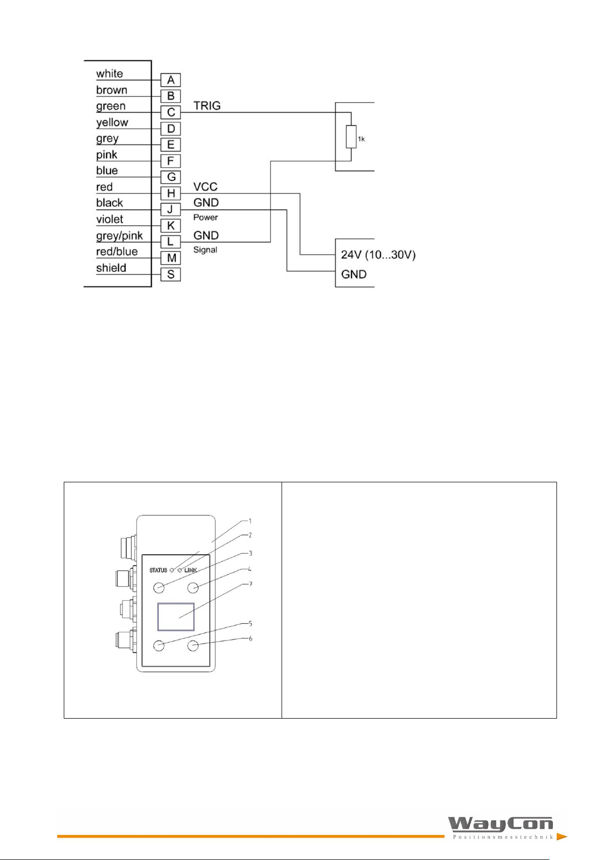
42
Output: Trigger (output) [TRO]: 0, 0
Figure 13: wiring of trigger output
6.9 Direct controlling of the LLD-500
The LLD-500 can directly be parameterized and set for measurements without an additional PC. Precondition is
that it is supplied with voltage through the interface cable. The LLD-500 is ready for operation when the green
STATUS LED is lit.
The individual menu items can be selected using 4 membrane keys, each 2 above and 2 below the OLED display. The user language is English.
The display can be deactivated during the measurement. It can be switched on again by pressing key T3 or T4.
1 Status LED off Power supply off
red Power supply on,
not ready for operation
green LLD-500 ready for operation
2 LINK LED off no data transfer
green, flashing
data transfer (Profibus/serial)
active
3 key T1 Function see display indication
4 key T2 Function see display indication
5 key T3 Function see display indication
6 key T4 Function see display indication
7 Display

43
STOP: Measurement will be stopped
Disp.: Display will be disabled
The display can be enabled with key T4 or T3.
Parameter setting
After STOP (measurement) parameters can be set.
Menu ↑ move cursor/ selection bar up
Menu ↓ move cursor/ selection bar down
Select select parameter
Meas.on start measurement
Execute command
Example „Identification“:
→
stop measurement
→
Status → Select
→
Identification → Select
Again repeat command
Return
return to upper menu
Figure 14: LLD-500 Display
Because of internal processing time it can be not guaranteed that all parameter changes will displayed after parameterizing of parameters (e.g. MF, SF, SA) via display input and a following check of the setup with command
PA. An action such as start/ stop of a measurement or input of command ID will update the values of parameter
PA.

44
7. Serial interface and communication software
7.1 Transmission protocol
► Interface settings: Asynchronous, 8 data bits, no parity, 1 stop bit
► Transmission protocol format / syntax: 7 bit ASCII
► Proprietary transmission protocol
► Commands are case-insensitive (NO differentiation between lower and upper case).
► Decimal separator in the output of figures is the dot “.” (0x2E).
► The terminator of a command (sending command) is the enter key (0x0D, 0x0A) or Carriage Return
(0x0D) or Line Feed (0x0A)
► Where parameters have several values, they are separated by a space (0x20).
► The response to commands with parameters is the respective command including the parameters.
► The response to commands without parameters is the respective command including the current
parameters.
► The response to commands with parameters outside of the valid value range is the respective
command including the current parameters.
The response to unknown commands and faulty parameter formats is a “?” (ox3F).
7.2 Installation of the communication program
HyperTerminal is a terminal program generally included in Win32 operating systems. It can be used as a communication program to parameterize the LLD-500.
Start HyperTerminal via the following menu path:
Start | Programs | Accessories | Communication | HyperTerminal|
Enter the name of the new connection in the dialog box.
You can select any name. Confirm with [OK].
Select the serial COM interface in the second dialog box.
Upon confirming with [OK] a third dialog box will appear where
the parameter settings for the current HyperTerminal session can
be selected.
LLD-500
LLD-500

45
At this point, baud rate (bits per second) and flow control must be initialized correctly. As soon as the settings in the third dialog box are
confirmed with [OK], the terminal window will open.
The status indication in the left bottom corner
reads “Connected” when the pre- conditions for
communication have been set correctly. As soon
as the LLD-500 is ready for operation (power supply, connection with PC), the commands can be
entered - e.g.: ID.
A command just entered will be displayed only when the “Local echo” function has been activated.
The function can be parameterized via the menu “File”.
|File | Properties | Setting |
|ASCII-configuration...|
Please note:
Do not tick the check box “Sent lines end with line feed”.
…

46
End the session with |File | Quit|.
A small window will appear where you are asked if the connection
should really be terminated. This question must be responded to by
pressing the [Yes] button.
If the current HyperTerminal session has not been saved yet, a
small window will appear where you are asked if the session
should be saved. Confirm with “Yes”. HyperTerminal will not have
to be configured again upon restart.
8. Profibus
8.1 ID-Number
The LLD-500 is registrated under ID number 0E36 (HEX) by PROFIBUS Nutzerorganisation e.V.
8.2 Connecting conditions
The LLD-500 can be connected to any Profibus-DP structure. The connected Profibus-DP master has to be able
to send a parameterization.
The master configuration tool (usually configuration software) must support the parameters of the GSD file
(GSD = General Station Description).
8.3 GSD-File
The GSD file is named LDM50E36.GSD.
It is a part of the CD LLD User Manual.
The current GSD on request.
The inclusion of the GSD file into the master configuration tool should be carried out to the documentation of the
configuration tool.
LLD-500

47
8.4 Slave address
The Profibus slave address can be set under consideration of the other Profibus slaves in the range of 0 … 126.
The address can be set with command SSAx via the serial interface or via the LLD-500 keys and the GUI
(graphical user interface) see chapter 6.4.21.
The documentation of the master configuration tool will inform how the slave address has to be changed via the
master configuration tool. The default address is 4. The slave address will be stored permanently in the
EEPROM and will be available even after power failure.
If several slaves are operated on a Profibus master they must have different addresses and have to connect
one by one.
8.5 Profibus termination
The Profibus termination is to realize externally. The supply voltage of 5 VDC will be supplied via Profibus OUT.
The 5 VDC are isolated galvanically from the power supply (VCC). The maximum load is 100 mA.
The terminator could be ordered with order number 94145.
8.6 Baudrate
The LLD Profibus has an automatic baud rate for the following baud rates: 9.6 / 19.2/ 93.75/ 187.5/ 500 kBaud
and 1.5/ 3/ 6/ 12 MBaud.
8.7 Length of segment
The maximum segment length between two Profibus participants depends on the selected baud rate. The following segment length must be observed:
Baudrate
Length of segment
9,6 kBaud …. 93,75 kBaud
1200 m
187,5 kBaud
1000 m
500 kBaud
400 m
1,5 MBaud
200 m
3 MBaud … 12 MBaud
100 m
Cable type A is strongly recommended for connection of different Profibus units. Cable type A has the following
properties:
Characteristic wave impedance
135 ... 165 Ω
Capacitance
< 30 pf / m
Loop resistance
< 110 Ω / km
Wire diameter
> 0,64 mm
Wire cross-section
> 0,34 mm2

48
8.8 Profibus Interface
The Profibus interface of LLD is a standard Profibus-DP V0 interface (local peripherals).
V0 is the version number. The telegrams are byte-oriented. Bytes are also referred to as Octets in Profibus
standard terminology. From the user’s angle, the description can be restricted to a few telegram types:
► Cyclical data exchange telegrams (DataEx)
► Diagnostic telegrams
► Parameter setting telegrams.
The different Profibus-slaves of the same or similar function are described in profiles. The profiles make it easier
for the user to use PB slaves having the same function but coming from different suppliers. For using LLD at the
Profibus, the encoder profile of the Profibus is supported. For this LLD serves as linear encoder. Under the encoder profile, LLD can work as Class1 or Class2 (recommended) encoder. All versions are implemented via
GSD file. In addition to profile-specific data, the LLD provides specific settings which refer to the control of the
laser and to diagnostics.
Profile
Class
Functions
Encoder
Class 1
Input only
Simple diagnostics
Minimum parameter setting
Class 2
Input and output (preset)
Extended diagnostics
Extended parameter setting
LLD
Class 1
See encoder profile
Class 2
Additional manufacturer-specific diagnostics and parameter setting
8.9 Configuration data
The configuration of the input and output data can be selected as follows:
Mandatory
class 1
D1 hex
2 words inputs, consistency
class 2
F1 hex
2 words of input data,
2 words of output data for preset value, consistency
class 2
D3 hex
4 words inputs, consistency
class 2
D3 E1 hex
4 words of input data
2 words of output data for preset value, consistency
class 2
98 A4 hex
9 bytes of input data
5 bytes of output data, consistency
optional
class 1
D0 hex
** not realized !! **
class 2
F0 hex
** not realized !! **

49
8.10 Cyclical data exchange – input (slave -> master)
Position data supplied by LLD-500 is signed. The sign can be inverted in the parameter SF (scale factor). The
resolution is also defined by SF. The arrangement of octets in the telegrams conforms to the Profibus (big endian), i.e., the MSB comes first, the LSB comes last.
Octet
Bit
Type
Output
1...4
signed 32
Position data from encoder in 0.1 mm
Configuration with 8 byte input and SS mode:
5...8
signed 32
Signal level
Configuration with 9 byte input:
9
signed 8
Temperature in °C
8.11 Cyclical data exchange – output (master -> slave)
The most significant bit in the present value (bit 32) defines the validity of the preset.
Octet
Bit
Type
Output
1..4 signed 32
Preset-Value
Normal mode: MSB = 0 (bit 31) Preset mode :
MSB = 1 (bit 31)
Configuration with 5 byte output:
5 0
1
2
3
4
bit
bit
bit
bit
bit
0:laser off, 1:laser on
0: normal – 1:ext. diagnostics with Exxxx 0: no
diagnostics, 1:Diag. as needed 0:no OLED
control, 1:OLED-Ctrl active 0:OLED off, 1:OLED
on
The internal offset can be set to a required value by the present. The offset can be changed by setting bit 31.
The following applies:
M
DataEx
Value transported on the Profibus in cyclical data exchange
M
Laser
Value measured by the laser
M
Offset
Offset calculated internally
Cyclical calculation of: M
DataEx
= M
Laser
+ M
Offset
The M
Offset
value can be written in the LLD-500 directly as parameter Octet 32...35 (see chapter 8.12) and can
be changed by cyclical data while the system is operating (and the configuration is as required, see chapter
8.3).
If bit 31 of M
preset
is set in the cyclical output data, M
offset
is updated. If bit 31 is zero, M
Offset
is not changed. The
new offset can be read as octets 30…33 in the diagnostic data.
Bit 31 has no particular release function for parameter data; the offset is always adopted.

50
8.12 Parameter data
At least the following parameters apply to class 1 devices:
Octet
Bit
Type
Output
1 byte
station status (Profibus default)
2 byte
wd_fact_1 (watch dog) (Profibus default)
3 byte
wd_fact_2 (Profibus default)
4 byte
min_tsdr (Profibus default)
5...6 word
ident number (Profibus default)
7 byte
group ident (Profibus default)
8 byte
spc3 spec (Profibus default)
9
0
bool
unused
1
bool
class 2 functionality on/off
2
bool
commissioning diagnostic on/off
3
bool
unused
4
bool
reserved for future used
5
bool
unused
6
bool
unused
7
bool
unused
As LLD is a linear encoder and measures absolute distances, the parameters
► “Code sequence”,
► “Scaling function control“,
► “Measuring units per revolution“ and
► “Measuring range in measuring units“ of the encoder profile are ignored.

51
For class 2 devices please use the following parameter:
Octet
Bit
Type
Output
10...13
unsigned 32
UNUSED – LINEAR ENCODER (MEASURING UNITS PER
REVOLUTION)
14...17
unsigned 32
unused – linear encoder (Measuring range in ...)
18...25
byte(s)
unused – (reserved for future use)
manufacture specific (LLD-500):
26
0 bool
unused 1
bool
unused
2...3
2 bit number
error reaction 0..2 [SEnn]
(0: last valid value, 1: min value, 2: max value)
4 bool
unused
5...7
3 bit number
measure mode [0:DT, 1:CT, 2:TDM]
27
0...1
2 bit number
TRI x 0..2
2...3
2 bit number
TRO x 0..2
4 bool
Q1 z 5
bool
Q2 z 6
bool
Q3 z 7
bool
unused
28…29
signed 16
TRI y : 0..32767
30…31
signed 16
TRO y : 0..32767
32…33
unsigned 16
SA x : 0,1..1000
34...37
unsigned 32
MF x : 0.0000..200.0000 (in 0.0001 steps)
38...41
unsigned 32
OF -2147483648... 2147483647
42...45
signed 32
SF -1000.000... 1000.000 in 0.001 steps)
46...49
signed 32
MW min -2147483648... 2147483647
50...53
signed 32
MW max -2147483648... 2147483647
54...55
unsigned 16
diag time (in 100 ms steps)
56...59
signed 32
Q1w -2147483648... 2147483647
60...63
signed 32
Q1x -2147483648... 2147483647
64...67
signed 32
Q1y -2147483648... 2147483647
68...71
signed 32
Q2w -2147483648... 2147483647
72...75
signed 32
Q2x -2147483648... 2147483647
76...79
signed 32
Q2y -2147483648... 2147483647
80...83
signed 32
Q3w -2147483648... 2147483647
84...87
signed 32
Q3x -2147483648... 2147483647
88...91
signed 32
Q3y -2147483648... 2147483647
92...95
signed 32
QAx -2147483648... 2147483647
96...99
signed 32
QAy -2147483648... 2147483647

52
8.13 Diagnostic data
Class 2 functionality
Commissioning diagnostic
Diagnostic Information
- 0
6 byte normal diagnostic
0 1
16 byte Class 1 diagnostic
1 1
61 byte Class 2 diagnostic
Octet
Bit
Type
Output
Profibus default diagnostic
1
byte
diag state 1
2
byte
diag state 2
3
byte
diag state 3
4
byte
master address
5...6 word
slave ident
class 1 diagnostic
7
byte
extended diag. header, length (class 1:0A, class 2:37)
8
byte
alarms – unused
9
0 bool
unused 1
bool
class 2 functionality on/off
2 bool
commissioning diagnostic on/off
3 bool
unused
4 bool
reserved for future used
5 bool
unused
6 bool
unused 7
bool
unused
10 byte
encoder type (=7 absolute linear encoder)
11...14
unsigned 32
single turn resolution => 100000nm = 0.1mm
15…16
unsigned 16
no. of distinguishable revolutions – unused (=0)

53
Octet
Bit
Type
Output
class 2 diagnostic
17
0 bool
E1001 "unexpected error"
1 bool
E1002 "mail-box error"
2 bool
E1003 "mutex error"
3...7
bool
-
18...19
0 bool
E1101 "pc usart error"
1 bool
E1102 "pc usart error"
2 bool
E1103 "laser usart error"
3 bool
E1104 "laser usart error"
4 bool
E1105 "laser usart error"
5 bool
E1106 "spi error"
6 bool
E1107 "spi error"
7 bool
E1108 "i2c error"
8 bool
E1109 "i2c error"
9 bool
E1110 "ssi error"
10
bool
E1111 "ssi error"
11
bool
E1112 "profibus error"
12
bool
E1113 "profibus error"
13
bool
E1201 "no destination found"
14
bool
E1202 "calibration error"
15
bool
E1203 "bad surface"
20...21
0 bool
E1204 "measure aborted"
1 bool
E1205 "measure running"
2 bool
E1206 "dest. too bright"
3 bool
E1207 "destination not in window"
4 bool
E1208 "parameter error"
5 bool
E1209 "no answer from laser"
6 bool
W1901 "reboot"
7 bool
W1902 "supply outer limit"
8 bool
W1903 "supply outer limit"
9 bool
W1904 "temp outer limit"
10
bool
W1905 "temp outer limit"
11
bool
W1906 "heating active"
12
bool
E1910 "measure time out"
13
bool
W1911 "measure frequ. too high"
14
bool
E1912 "."
15
bool
-
22...23 word
warnings – unused (=0)
24...25 word
Profile Version (e.g. 1.1 = 0110 hex)
26...27 word
Software Version (e .g. 1.11 = 0111 hex)
28...31
unsigned 32
operating time (of laser), in 0.1 hours
32...35
signed 32
offset value (see output data)
36...39
signed 32
manufacture offset – unused (=0)
40...43
unsigned 32
measuring units per revolution – unused (=0)
44...47
unsigned 32
measuring range – unused (=0)
48…57
10 byte
serial number
58...59
signed 16
laser temperature in °C
60 byte
reserved - unused
61 byte
reserved - unused

54
8.14 Tips for start-up (Siemens STEP7)
The programming software must be made familiar with the possibilities of the LLD-500:
► Open the Simatic Manager
► Open HW Config
► Extras – install new GSD file
► Select LDM50E36.GSD
After that LLD-500 can be integrated at the Profibus:
Select DP slave at ‘Other field devices‘– ‘Encoder’ – LLD-500
A Profibus address must be assigned to LLD-500 (in SSA Set Slave Address):
Target system – Profibus – Assign Profibus Address
8.15 Error display
External errors are not displayed at the module.
8.16 Monitoring
Set to a trigger time of 500 ms, a watchdog internal to the PU monitors the functioning of the module. The following functions are monitored:
► the main loop with Profibus request processing
► the laser control
► the update function.
In case of transient errors (ESD, program error…) the module can be started again after a watchdog reset. Each
reset increments the watchdog counter by one.
Other reset causes are also counted:
► Spike detection reset
► SW reset
► Programming and debug reset
► Brownout reset (monitoring of the operating voltage)
► External reset
► Power-on reset
8.17 Service program SL5.exe
8.17.1 Overview
The service program SL5.exe supports the commissioning.
All settings are made into a SPS directly have to perform according to the specifications of the manufacturer of
SPS.
The service program can be purchased along with an USB master of softing.
Order number: 95831
After installation of a Profibus master, product of softing, the related drivers (also see 2.4.), the service program
for lasers LLD-150-PROF and LLD-500 (SL5.EXE) can be started. The program as such does not need an installation (it is linked statically). Only the papi.dll for the Profibus must be placed in the folder.
Copy the service program SL5.EXE and the papi.dll file in any network folder and execute SL5.EXE.

55
In the SL5.EXE program, confirm the four big buttons on the left one after the other, starting from top.
If a computer contains several PB masters, a master module on the right of the word “Board” can be selected
with the combo-box. The selected master module will be analyzed and its type displayed on the right of it, e.g.
PROFIboard PCI or PROFIcard.
1. Press the Connect button
The selected board is activated and – if successful - the ‘Go Online’ button enabled. If a problem
occurs, open ‘Trace’ with a mouse-click on the ‘Trace’ tab (in the middle of the dialog) for more
information on the Profibus. On the right of the word ‘Master:’ an address can be assigned on the Profi-
bus with the combo- box of the PB master module. Every address must be unique! Depending on what
type of Profibus is connected, different PB masters and PB slaves with ad- dresses in the range 0…125
can be available. Normally, the preset 0 as address of the PB master is okay. The baudrate should be
set as a function of the length of the line or masters already active on the bus
2. Press the Go Online button
The PB master will become active on the bus (exchanges the token). If everything is okay, the ‘Scan for
Slave’ button will be enabled after about 2 seconds. Now the bus can be searched for slaves. The
search always begins at address 0. The master address is skipped. To cut the search short, the highest
address to be used can be defined.
3. Press the Scan for Slave button
A search of the bus is made and the first LLD-500 found is selected as slave. If the slave address (‘se-
lect addr :’) is changed, a diagnosis request is sent to the slave and the PNO Ident of the slave dis-
played when the reply is received.
4. Press the Data Exchange button
The master adopts Operate state, sends a data exchange request to the LLD-500, whereupon the latter
activates its laser. The distances measured can be viewed at Distance.

56
8.17.2 Setting a Profibus slave address at the LLD-500
Perform steps 1 to 3 in chapter 8.17.1. One LLD-500 PI-LB module must have been found at the bus. The Profibus slave address of that module can now be changed to between 0 and 125 but the addresses of other bus
users must not be assigned to the module. For this, select ‘old addr:’ the current address and the required new
address at ‘new addr:’ Then press ‘Set Addr’. ‘Set Slave address’ (SSA), a Profibus global control, transfers the
new ad- dress to the PB slave, which uses the new address henceforth. The new address is stored permanently
in the EEPROM and is the new slave address also after a power outage
8.17.3 Parameter-Dialog
The SL5 generates a complete encoder profile specific parameter record, which is transmitted to the slave immediately when a datum is changed (provided it is active on the bus).
(Profibus) parameters cannot be read back.
Therefore, the setting of the parameters may not agree with the parameters active in the slave when the SL5 is
started.
► Class 2 function: Selection of the slave type according to the encoder profile
► Commissioning diagnostic: Send more than the 6 Byte standard diagnostic (16 Byte as Class1 slave, 61
Byte as Class 2 slave)
► Tracking mode: Mode (trigger) of the laser (DT,CT,TDM)
► Trigger input flank and time spacing: Values are transferred directly to the TRI x y command
► Trigger output flank and time spacing: Values are transferred directly to the TRO x y command
► Averaging: Value is transferred to the SAn command
► An offset can be applied to the measuring value (correction).
► Scale factor: Scaling factor –1000,000... +1000,000. Up to 3 decimal digits are processed.
► Error mode: Selects the distance value in case of an error
► Measure frequency: Measuring time output, 0 means no firm frequency, range 0.0 ...
200.0 with up to 4 decimal digits
► Measure window: Setting of the valid measuring window
► Diagnostic interval: 0=Send diagnostic data only in case of alarm, 1..10000 : Send diagnostic data every
n x 100 ms
► Switched output Q1/2/3: Switching threshold for output n in units of distance – is transferred to Q1/2/3
command
► Analog switched output: min. and max. distance values for 4 and 20 mA
8.17.4 Diag Common
The (general) diagnostic data is in full agreement with the profile standard and is updated by every Profibus diagnostic request. The Common Diag data requires Class2 functionality and the Commissioning diagnostic function. In case of error (Ennnn) or warnings (Wnnnn) an alarm message with all diagnostic data is sent as extended diagnostic. To view temperature and operating time, set the diagnostic interval other than 0. A diagnostic
interval of 100 causes an update every 10 secs.
8.17.5 Diag Alarm
Alarm messages of the laser module are sent once as EXT. DIAG. Active alarms are marked X instead of –.
Alarms are counted but not stored anywhere. If an error occurs, it is reported as Ext. Diag and then an attempt
at reactivating the laser is made. Thus, permanently active errors increment the appropriate error count.
8.17.6 Trace
Here, certain messages will be displayed for diagnostic purpose if problems occur with the Profibus or the PB
master in the PC.

57
8.17.7 Log-File
If required, the SL5 program can write distances and temperature in a log file in regular intervals. The log file
can have a firm name. For this, uncheck the ‘automatic’ box. Select a target folder and a file name with the
Browse button (‘...’). Data will then be written in that file continuously. For longer recording times, the log can be
split into day files. For this, check the ‘automatic’ box. This generates a file by the generic name ‚ L5_yymmdd’
(yy=year, mm=month, dd=day). That file is closed at midnight and a new file generated for the next day. The
system time (UTC, GMT) is used as file time.
The file is written with special ‘share’ attributes so that it can be read by other programs (data- bases, control
systems...) at the same time. Also see tail programs. Under Values, select the values to be written. Under Time,
enter the time spacing between 2 values in minutes and/or seconds.
The log can be started or stopped at any time with Start and Stop.
The message in the messages window contains additional information whether the module is supplying distance
or temperature data.

58
9. Error processing
In case of errors or when a measured value cannot be determined or put out, a warning or an error message will
be displayed
Error
Meaning
Action
e1001
Error operation system/ firmware
Restart system
e1002
Error operation system/ firmware
e1003
Error operation system/ firmware
e1101
Error in communication with PC
check connection to external system/ contact service for repair
e1102
Error in communication with PC
e1103
Laser module error
contact service/ send LLD-500 to
supplier
e1104
Laser module error
e1105
Laser module error
e1106
Hardware error (internal data transfer)
e1107
Hardware error (internal data transfer)
e1108
Hardware error (controller)
e1109
Hardware error (controller)
e1110
Hardware error (SSI)
e1111
Hardware error (SSI)
e1112
Hardware error (Profibus)
e1113
Hardware error (Profibus)
e1201
Measurement impossible / no target
adjust device/ check target
e1202
Error measuring module (calibration)
contact service/ send LLD-500 to
supplier
e1203
Target with unsuitable reflectivity
check target and distance
e1204
Measurement interrupted (measuring module)
Restart system
e1205
Measurement still running (measuring module)
Restart system
e1206
Target too bright / too much back light
check/ limit ambient light
e1207
Target outside of the measurement window (MW)
no action or change MW setup
e1208
Incorrect measurement parameterization
check setup
e1209
Hardware error (measuring module)
contact service/ send LLD-500 to
supplier
e1210
Current of laser is over the limit (laser stops work)
Restart of measurement (e.g. DT)
e1211
Stop of measurement (internal error)
Restart of measurement (e.g. DT)
Warnings
Meaning
Action
w1901
Restart being executed
no action
w1902
Input voltage outside of the specification (too low)
check power supply (10…30 VDC)
w1903
Input voltage outside of the specification (too high)
w1904
Temperature outside of the specification (too low)
check ambient temperature
w1905
Heating active, min. temperature not reached, no
measurement possible
no action/ wait until LLD-500 is
ready
w1906
Temperature outside of the specification (too high)
check ambient temperature
w1907
Trigger input and trigger output active at the same
time
Activate TRI or TRO, not both for
the same system
w1910
Measurement not completed within predefined
period of time
use variable measuring time (MF0)/
check target
w1911
Measuring frequency too high
change MF
w1912
Distance jump
Make sure a continuous movement
of target

59
10. Technical Data
Measurement properties
Measurement principle
Pulse reflection mixing method
Measured parameter
Distances
Measuring range1
Total
Onto Oralite 5200 target board
Onto 3M 3279 special target board
Onto natural surfaces, 80% remission
Onto natural surfaces, 6% remission
0.15 m … 200 m
50 m … 200 m
0.15 m …100 m
0.15 m …100 m
0,15 m …85 m
Measurement accuracy1 (1 σ)
< + 3.9 mm
Repeatability
+ 0.6 mm
Resolution of measured values
0.1 mm
Measuring period, minimum
10 ms
Laser
Laser classification
Laser class 2, EN 60825-1:2014
Wavelength
635 nm
Divergence
< 0.2 mrad (50 % laser power)
Laser spot in 10 m
4 mm x 5 mm
Environmental and application conditions
Supply voltage
10 V ... 30 V DC
Power consumption
< 10 W (without heating)
< 42 W (with heating, 24 V)
Interface/ connections
Connections (on device)2
x 12-pole (BINDER series 723) M16
x 5-pole (BINDER series 766) M12, B-type encoded 1 x 5-pole
(BINDER series 763) M12, A-type encoded
Serial interfaces
RS232, RS422, RS485
Switching output
3 x “high side”, can resist up to 0.2 A
Analog output
4 mA … 20 mA
Error handling at 3 mA / 21 mA
Total output error at 20 mA: + 0.15 % at a temperature of
25°C

60
Trigger, input + output
1x
Profibus
Profibus
DP-V0 Slave | IEC 61158 / IEC 61784
Transmission rate
9,6 kBaud ... 12 MBaud
Identity number
0E36 HEX
Baudrate recognition
Automatic
terminating resistance
External
Slave address
Can be set via display or SSA command
GSD file
LDM50E36.GSD, PNO-Profile Encoder Class 1/2
Configuration of measurement parameters, switching outputs, trigger connection and starting behavior
Output of measured distance values or error messages, monitoring of internal device temperature
Storage of all parameters and PB address in NVRAM
SSI
clock rate
200 / 250 / 300 kHz, 25 µs pause
Signal input/output
Difference signal (RS422)
24 bits, binary or Gray-encoded, adjustable
1 validity bit
Potential separation
500 V for signal input
LSB
Bit 0
MSB
Bit 23
Indicating and operating elements
2 status LEDs
4 membrane keys
1 OLED matrix display
Environmental and application conditions
Operating temperature2
-40 °C … + 60 °C (-10 °C … + 60 °C)
Storage temperature
-40 °C … + 70 °C
Humidity
15 % … 90 %, non-condensing
Housing protection class
IP67
EMC
EN 61326-1
Dimensions
120 mm x 76.5 mm x 40 mm (L x W x H, incl. connections)
Weight2
approx. 700 g
1
Range for natural, diffusely reflective surfaces; dependent on target reflectivity, stray light, measuring frequency and environmental condition
Measurement accuracy dependent on target reflectivity, measuring frequency and environmental conditions
2
Dependent on the type of device
 Loading...