

Page 1
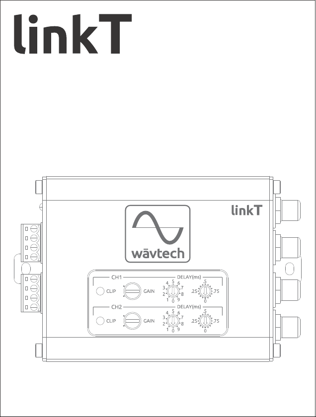
2-Channel LOC / Line Driver + DSP
Digital Time Alignment
Ÿ
Ÿ
Independent Channel Gain
Ÿ
OEM Load Detect Compatible10Vrms Output
Owner’s Manual
www.wavtech-usa.com
Page 2
WARNING
CAUTION
This symbol means important instructions.
Failure to heed them can result in serious injury or death.
This symbol means important instructions.
Failure to heed them can result in injury or property damages.
• DO NOT DRIVE WHILE DISTRACTED. Any function that requires your prolonged
attention should not be performed while driving. Always stop the vehicle in a safe
location before performing any such function. Failure to do so may result in an accident.
• KEEP THE VOLUME AT MODERATE LEVELS WHILE DRIVING. Excess volume levels
can obscure sounds such as emergency vehicle sirens or road warning signals and may
result in an accident. Continuous exposure to high sound pressure levels may cause
permanent hearing loss. Use common sense and practice safe sound.
• FOR USE WITH 12V NEGATIVE GROUND VEHICLE APPLICATIONS ONLY. Using this
product other than in its designed application may result in fire, injury or product
damage.
• MAKE THE CORRECT WIRING CONNECTIONS AND USE PROPER FUSE PROTECTION.
Failure to connect wiring correctly or use appropriate fuse protection may result in fire,
injury or product damage . Ensure proper fusing of all system power wiring and install a 1ampere in-line fuse (not included) with the +12V lead to the unit’s power supply
connector.
• DISCONNECT THE NEGATIVE BATTERY TERMINAL BEFORE INSTALLATION. Failure
to do so may result in fire, injury or damage to the unit.
• D O NOT ALLOW CABLES TO BECOME ENTANGLED IN SURROUNDING OBJECTS.
Arrange wiring and cables to prevent obstructions when driving. Cables or wiring that
obstruct or hang up on places such as steering wheel, brake pedals, etc. can be extremely
hazardous.
• DO NOT DAMAGE VEHICLE SYSTEMS OR WIRING WHEN DRILLING HOLES. When
drilling holes in the chassis for installation, take precautions so as not to contact,
puncture or obstruct brake lines, fuel lines, fuel tanks, electrical wiring, etc. Failure to
take such precautions may result in fire or an accident.
• DO NOT UTILIZE OR CONNECT TO ANY PART OF VEHICLE SAFETY SYSTEMS. Bolts,
nuts or wires used in the brake, airbag, steering or any other safety-related systems or
fuel tanks should NEVER be used for mounting, power or ground connections. Using such
parts may disable control of the vehicle or result in fire.
CAUTION
• STOP USE IMMEDIATELY IF A PROBLEM OCCURS. Failure to do so may result in
personal injury or damage to the product. Return it to your authorized Wāvtech dealer.
• HAVE AN EXPERT DO THE WIRING AND INSTALLATION. This unit requires special
technical skill and experience for wiring and installation. To insure safety and proper
function, always contact the authorized dealer where you purchased the product to have
it done professionally.
• INSTALL THE UNIT SECURELY WITH SPECIFIED PARTS. Be sure to use only the
included parts and specified installation accessories (not included). Use of other than
designated parts may damage this unit. Install the unit securely so that it will not come
loose during a collision or sudden jolt.
1
WARNING
Page 3
• ROUTE WIRING AWAY FROM SHARP EDGES AND MOVING PARTS. Arrange cables and
wiring away from sharp or pointed edges and avoid moving parts such as seat hinges or
rails to prevent pinching or wear. Use loom protection where appropriate and always use
a grommet for any wiring routed through metal.
• NEVER RUN SYSTEM WIRING OUTSIDE OR UNDERNEATH THE VEHICLE. All wiring
must be routed, secured and protected inside the vehicle. Failure to do so may result in
fire, injury or property damage.
• INSTALL THE UNIT IN A DRY AND VENTILATED LOCATION. Avoid mounting locations
where the unit will likely be exposed to high moisture or heat without adequate
ventilation. Moisture penetration or heat buildup may result in product failure.
• REDUCE GAIN AND SOURCE VOLUME TO MINIMUM LEVELS FOR INITIAL SYSTEM
TUNING AND BEFORE CONNECTION TO AN AMPLIFIER. Ensure amplifier power is off
before connecting RCA cables and follow proper system gain setting procedures. Failure
to do so may result in damage to the amplifier and/or connected components.
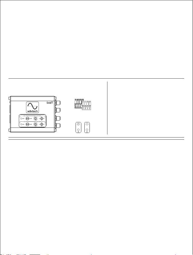
Package Contents:
Main Unit Terminals
(2pcs, detachable)
Mounting Tabs
(2pcs, detachable)
Accessories Required for
Installation (not included):
Ÿ RCA Interconnects
Ÿ 18AWG Wire
Ÿ In-line Fuse Holder w/1A fuse
Ÿ Battery Ring Terminal
Ÿ Ground Terminal
Ÿ Wire Crimp Connectors
Ÿ Grommets and Loom
Ÿ Cable Ties
Ÿ Mounting Screws
Introduction
Welcome to Wāvtech, exceptional mobile audio integration products for
audiophiles. Our products are engineered to provide a truly remarkable
listening experience. Built for the professional installer, our OEM integration
and signal processor models are simply the best solution available for unlimited
sound system upgrades while retaining the factory receiver.
Features
Ÿ 2-Channel Digital Time Alignment Processor
Ÿ 2-Channel Line Output Converter or Line Driver
Ÿ Differential Balanced Inputs
Ÿ Low Impedance Outputs
Ÿ Independent Variable Gains with Clip LEDs
Ÿ Auto Turn-On via DC-Offset or Audio Signal Detect
Ÿ Generated +12V Remote Output
Ÿ OEM Load Detect Compatible
Ÿ Selectable Ground Isolation
Ÿ Detachable Power and Speaker Input Terminals
Ÿ Professional Grade Panel Mount RCA Output Jacks
Ÿ Aluminum Chassis w/Detachable Mounting Tabs
2
Page 4
Connections & Functions
Œ
Ž
‘
’
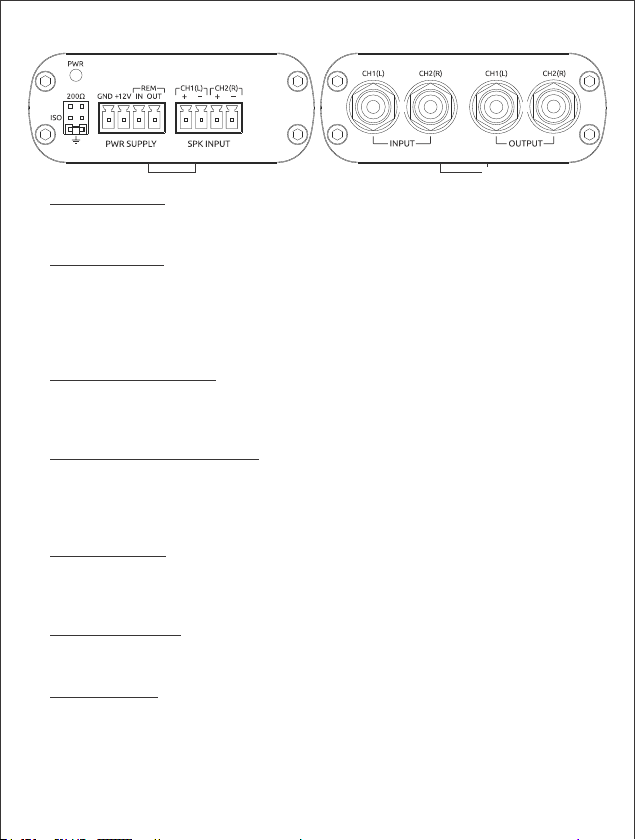
ΠPower Indicator: This red LED indicates when the linkT is powered on. Once
illuminated, there will be a short delay before audio signal output is enabled.
During initial power connection, the LED may illuminate for a brief period.
Ground Jumper: For selecting between chassis, isolation or 200Ω for the
internal audio signal ground. Chassis ground is the default setting and is
ideal for most applications due to the differential input stage. In the rare
case there is system noise present after all other installation
countermeasures, changing this jumper to ISO or 200Ω may reduce or
eliminate the noise.
Ž Power Supply Terminal: For +12V battery, chassis ground, remote input and
remote output wire connections. A minimum of 18AWG wire is
recommended for power and ground connections. Always protect the +12V
power wire with a 1-amp fuse.
Speaker Level Input Terminal: For left and right channel speaker level (a.k.a.
high level) connections to the source. Input signals ranging from 2Vrms to
20Vrms will produce up to 10Vrms RCA output at maximum to minimum gain
setting. Dynamic music signal peaks are allowable up to 40Vrms, but will be
clipped. Use this input if your source unit does not have RCA outputs.
RCA Input Jacks: For left and right channel low level (a.k.a. line level) signal
connections to the source unit. Input signals ranging from 0.5Vrms to 5Vrms
will produce up to 10Vrms RCA output at maximum to minimum gain setting,
individually adjustable per channel.
‘ RCA Output Jacks: For left and right channel line level signal connections to
your amplifier(s). Use quality interconnects to ensure stable connections and
minimize the possibility for induced noise.
’ Mounting Tabs: These mounting tabs are pre-attached and should be used
to properly secure the linkT during installation with screws or cable ties.
They are removable if the unit can be safely secured by another method.
3
Page 5

Installation & System Wiring
It is important to read this manual thoroughly before starting your installation
and always plan accordingly. Before installing any Wāvtech product, disconnect
the negative (ground) wire from the vehicle’s battery to avoid damage to the
vehicle or yourself. Following all guidelines will help provide years of enjoyment
with your Wāvtech linkT audio interface.
Ground Connection (GND): The GND terminal must be connected to a metal
part of the vehicle that is welded to the vehicle body with ground plane back to
the main battery ground attachment point (a.k.a. chassis ground). This wire
should be a minimum of 18AWG and as short as possible to minimize potential
for noise to enter the system. The chassis ground connection point should have
all of the paint removed and be scuffed to the bare metal. The ground wire
should be terminated by a ground specific interlocking terminal such as the
EARL terminal or ring terminal securely bolted to the vehicle with star or lock
washer and nut to prevent it from coming loose. Avoid using factory ground
points to reduce the chance of induced noise from other components.
Power Connection (+12V): The constant power connection should be made at
the vehicle battery when possible. For direct battery connection, a 1-amp fuse
must be installed in-line with the power wire within 18”of the battery and
securely connected to the positive battery terminal bolt with a ring terminal. If
connecting to another available constant +12V power source, a 1-amp in-line
fuse must be added at the connection point. The power wire should be a
minimum of 18AWG. Do not install the fuse until all other system connections
have been made.
Speaker Level Inputs (SPK): Connect the speaker wires from the source unit to
the corresponding input terminals at the interface. Always ensure correct
polarity of each channel when making these connections, as failure to do so can
severely effect sound performance.
Remote Input (REM IN): If the source unit has a remote output wire (provides
+12V only when turned on), connect it to the REM IN terminal. If a remote lead
is unavailable, the linkT is also enabled with an automatic turn-on circuit that
detects audio signal from SPK and RCA inputs, as well as DC-offset from SPK
inputs. While auto turn-on will work in most applications, there may be some
cases were detection level is not satisfactory and connecting a +12V trigger to
REM IN is needed.
Remote Output (REM OUT): Use the remote output to provide a +12V trigger
to turn on amplifiers or other components. This +12V output is generated
internally by the interface when turned on either by REM IN or automatic
sensing, and will provide over 500mA continuous current for external devices.
4
Page 6
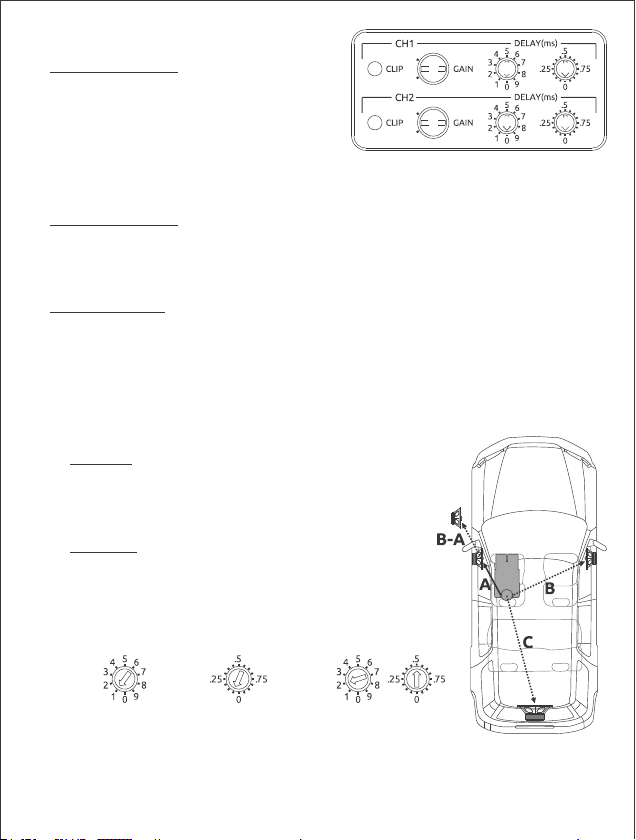
Top Panel Adjustments
ΠClipping Indicators: These yellow LEDs
indicate when the output signal from
each channel is at maximum level
before clipping (distortion) occurs. Each
will be dimly lit just below the onset of
clipping, and full bright at clipping.
Since the linkT will produce over 10Vrms at full output, gain may need to be
reduced well below the point of illumination in order to match your
amplifier’s maximum input capability or optimize source volume range.
Œ
Œ
Gain Adjustments: These gain adjustments are for matching each channel’s
output signal level of the linkT with the maximum unclipped signal range
from the source and maximum input capability of your amplifier(s). Follow
proper gain setting procedures to ensure optimum source volume range
with minimum chance for clipping at any point in the signal chain.
Ž Time Alignment: These rotary switches are for selecting the amount of time
delay applied to CH1 and CH2 outputs. Each channel has two switches, one
for milliseconds and another for fractions of a millisecond. These separate
digits allow for quick coarse adjustment and simple fine tuning by ear or
distance measurement. If adjusting for individual loudspeaker alignment
such as between a tweeter and midrange, it is recommended to first start
with delay based upon the measured difference in distance to the listening
position, then fine tune by ear using a high resolution music track with
known instrument placement and staging.
1st Digit: This rotary switch provides delay in 1ms
increments in 9 steps for up to 9ms. Each step is
equivalent to 13.5in (34.3cm) in distance. Use this
adjustment for initial coarse delay settings for
larger differences to the listening position.
2nd Digit: This rotary switch provides delay in
0.0625ms increments in 15 steps for up to 0.94ms.
Each step is equivalent to 0.85in (2.1cm). Once the
imaging is set close to the desired result with course
adjustment, or for differences less than 1ms, use
this rotary to fine tune imaging and focus.
st
1 Digit
nd
2 Digit
Example:
Ž
Ž
1ms/step
= 13.5in(34.3cm)
Note: When using the linkT to optimize left/right stereo imaging, delay the closest speaker
(A) by the difference between it and the furthest speaker (B) to the listening postion (B-A),
or simply adjust by ear for desired image placement. If a subwoofer is also present, once
stereo imaging is set, both channels can then be further delayed equally by the additional
distance from the subwoofer (C-B), or until the perception of up front bass is achieved.
0.0625ms/step
= 0.85in (2.1cm)
2ms + 0.5ms = 2.5ms
= 33.75in (85.75cm)
5
Page 7
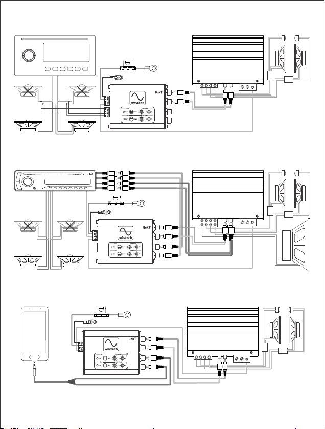
System Examples
Example-1: Speaker Level Input from OEM Radio
GND
SPK IN
Note: When using a receiver’s internal power IC to drive speakers directly and provide the
linkT with signal, note that its speaker outputs will likely clip below the maximum master
volume level. Adjust gain settings accordingly for optimum unclipped volume range.
+12V
REM
OUT
Example-2: RCA Input from Aftermarket Radio
REM
IN
Note: When adding time alignment only for front speakers and retaining deck power to
rear speakers, it is recommended to use the fader to reduce rear speaker level enough to
provide some ambience while minimizing any affect to front staging and image focus.
GND
+12V
RCA IN
RCA OUT
REM OUT
Example-3: RCA Input from Portable Audio Player
GND
+12V
REM OUT
Note: Portable devices such as smartphones or MP3 players typically have an output
voltage of 1Vrms or less. While the linkT’s auto turn-on circuit will detect very low signal
levels, in some cases the gains may need to be adjusted for reduced total volume range
when using the portable device as the system master volume control.
6
Page 8
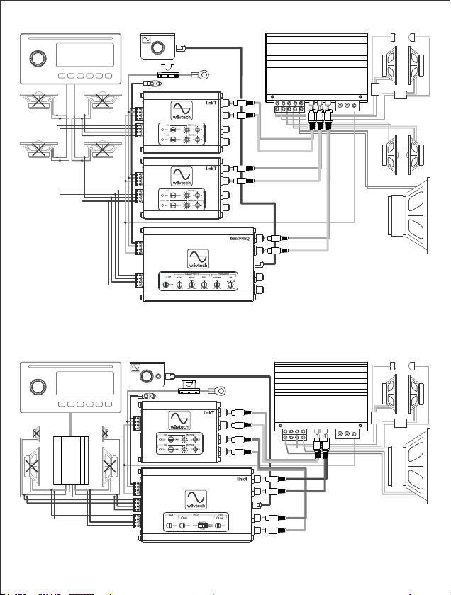
Example-4: Multiple Channels & System Expansion
RLC
GND
CH1/2 IN
+12V
CH1/2 OUT
CH3/4 IN
Note: Multiple linkTs can be used for aligning more channels such as front and rear, biamped components, or large subwoofer systems. Other Wāvtech models can also be added
for additional conversion channels and features. In this example, the bassFREQ provides
remote level control, parametric EQ and -24dB/oct crossover for a subwoofer.
CH3/4 OUT
REM OUT
SUB OUT
Example-5: Post Process Time Alignment
RLC
GND
CH1/2
CH3/4
Note: When adding the linkT for time alignment after another Wavtech model such as the
link4, adjust the link4’s gain to both maximize the linkT’s input signal without clipping and
match its output with the input capability of the connected amplifier(s).
+12V
OUT
IN
CH3/4
CH1/2
REM
OUT
7
Page 9
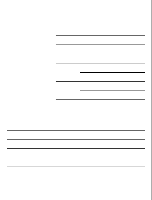
Specifications
Frequency response
Input Impedance
Input Sensitivity
Max Input Voltage (peak)
Output Impedance
Max Output Voltage
THD+N
S/N (signal-to-noise)
Time Alignment
Turn-On Trigger
Remote Output
Current Draw
Operating Voltage (B+)
Product Dimensions
Note: Specifications are subject to change without notice.
Max Flat (+0/-1dB)
Extended (+0/-3dB)
Spk Input
RCA Input
Spk Input (max-min gain)
RCA Input (max-min gain)
Spk Input <5sec 40Vrms
RCA Input <60sec 15Vrms
at 1% THD+N
Spk Input at 10V output
RCA Input at 10V output
Spk Input
RCA Input
Delay Range
Increments
Remote
DC-offset
Audio Signal
Current Capacity
Voltage
Max Draw (w/o REM OUT)
Sleep Current
Power On
Power Off
Chassis (not incl. terminals)
at 1V output
at 4V output
at 10V output
at 1V output
at 4V output
at 10V output
st
1 Digit
nd
2 Digit
via REM IN
via Spk Input
via Spk Input
via RCA input
Turn-off Delay
<20Hz to >36kHz
<10Hz to >44kHz
180Ω
20kΩ
2 - 20Vrms
0.5 - 5Vrms
<50Ω
>10Vrms
<0.1%
<0.05%
>75dBA
>87dBA
>95dBA
>75dBA
>87dBA
>95dBA
9.94ms (11.2ft/3.4m)
1ms (13.5in/34.3cm)
0.0625ms (0.85in/2.1cm)
>10.5V
>1.3V
<100mV
<10mV
up to 60sec
>500mA
Within 3% of B+
<300mA
<2.3mA
10.5V-18V
<8.5V
1.1”x2.9”x3.7”
29x75x93mm
8
Page 10

Installation Notes
Vehicle Description
Ÿ Year, Make, Model:
Ÿ Trim Level / Package:
OEM Audio System Info
Ÿ Head Unit (type, BT/AUX in, etc.):
Ÿ Speakers (size/location, etc.):
Ÿ Subwoofer(s) (size/location, etc.):
Ÿ Amplifier(s) (location, output voltage, etc.):
Ÿ Other:
linkT Connections & Settings
Ÿ Installed Location:
Ÿ Wiring (connection locations, signal type, turn-on mode, etc):
Ÿ Level Settings (gain position, max master vol, etc.):
Ÿ Other:
System Configuration:
System Diagram
9
Page 11

Warranty & Service Care
Wāvtech warrants this product to be free from defects in material and workmanship for a
period of one (1) year when purchased from an authorized Wāvtech retailer within the United
States. This warranty will be extended to a period of two (2) years when the installation is
performed by an authorized Wāvtech retailer. A valid sales receipt is required to verify
eligibility of purchase and installation.
This warranty is valid only to the original purchaser and is not transferrable to subsequent
parties. This warranty is void if the product serial number has been altered or removed. Any
applicable implied warranties are limited in duration to a period of express warranty as
provided herein beginning with the date of the original purchase at retail, and no warranties,
whether expressed or implied, shall apply to this product thereafter. Some states do not allow
limitations on implied warranties, therefore these exclusions may not apply to you. This
warranty gives you specific legal rights. You may also have other rights which vary from state
to state.
If your product needs service, you should contact Wāvtech Customer Service to receive a
Return Authorization (RA) Number. Any product received without an RA number will be
returned to sender. Once your product is received and inspected by customer service,
Wāvtech at its sole discretion, will be repair or replace it with a new or remanufactured
product at no charge. Damage caused by the following is not covered under warranty:
accident, abuse, failure to follow instructions, misuse, modification, neglect, unauthorized
repair or water damage. This warranty does not cover incidental or consequential damages.
This warranty does not cover the cost of removing or reinstalling the product. Cosmetic
damage and normal wear are not covered under warranty.
For Service within the United States:
Wāvtech Customer Service: (480) 454-7017
Monday – Friday, 8:30am to 5:00pm MST
Serial Number:
Installation Date:
Place of Purchase:
Important Notice for International Customers:
For products purchased outside the United States of America or its Territories, please contact
your local distributor concerning specific procedures for your country's warranty policy.
International purchases are not covered by Wāvtech, LLC.
10
Page 12

Wāvtech™
7931 E. Pecos Rd
Suite 113
Mesa, AZ 85212
(480) 454-7017
©Copyright 2017 Wāvtech, LLC. All Rights Reserved.
 Loading...