

Wavion WCN2400 1 User Manual

WCPEn-2400-I Quick Start Guide
February 2012
Version 1.0

Contents
1. INTRODUCTION ............................................................................................................. - 4 -
1.1 KEY FEATURES ................................................................................................................... - 4 -
2. INSTALLATION .............................................................................................................. - 5 -
2.1 PACKAGE CONTENTS ............................................................................................................ - 5 -
2.2 PRODUCT LAYOUT ............................................................................................................... - 5 -
2.3 INSTALLATION AND SET-UP ................................................................................................... - 6 -
2.3.1 Installing the WCPEn-2400-I ....................................................................................... - 6 -
2.4 CONNECTING POWER AND DATA ............................................................................................. - 7 -
2.4.1 Accessing the WCPEn Management Interface .............................................................. - 7 -
3. CONFIGURING WCPEN .................................................................................................. - 8 -
3.1 GENERAL CONFIGURATION .................................................................................................... - 8 -
3.1.1 Setup ........................................................................................................................ - 8 -
3.1.2 Operation Mode ......................................................................................................... - 8 -
3.1.3 Specifying Wireless settings ...................................................................................... - 14 -
3.1.4 Security Settings ...................................................................................................... - 15 -
3.2 GENERAL ADMINISTRATION TASKS .......................................................................................... - 15 -
3.2.1 Firmware Upgrade ................................................................................................... - 15 -
3.2.2 Restoring Settings .................................................................................................... - 15 -
3.3 STATUS ............................................................................................................................ - 16 -
3.3.1 Checking System Setup ............................................................................................ - 16 -
3.4 CONFIGURATION ................................................................................................................ - 16 -
3.4.1 System Setup .......................................................................................................... - 16 -
3.4.2 IP Management ....................................................................................................... - 17 -
4. APPENDIX B: TROUBLESHOOTING .............................................................................. - 18 -
4.1 BASIC TROUBLESHOOTING .................................................................................................... - 18 -
4.2 LED DESCRIPTIONS ............................................................................................................ - 18 -
WCPEn 1.0 User Guide Page - 2 -

FCC Statement
Federal Communication Commission Interference Statement
This equipment has been tested and found to comply with the limits for a Class B digital device, pursuant to Part 15 of the FCC
Rules. These limits are designed to provide reasonable protection against harmful interference in a residential installation. This
equipment generates, uses and can radiate radio frequency energy and, if not installed and used in accordance with the
instructions, may cause harmful interference to radio communications. However, there is no guarantee that interference will not
occur in a particular installation. If this equipment does cause harmful interference to radio or television reception, which can be
determined by turning the equipment off and on, the user is encouraged to try to correct the interference by one of the following
measures:
● Reorient or relocate the receiving antenna.
● Increase the separation between the equipment and receiver.
● Connect the equipment into an outlet on a circuit different from that to which the receiver is connected.
● Consult the dealer or an experienced radio/TV technician for help.
FCC Caution: Any changes or modifications not expressly approved by the party
responsible for compliance could void the user’s authority to operate this equipment.
This device complies with Part 15 of the FCC Rules. Operation is subject to the following two conditions: (1) This device may not
cause harmful interference, and (2) this device must accept any interference received, including interference that may cause
undesired operation.
For product available in the USA/Canada market, only channel 1~11 can be operated. Selection of other channels is not possible.
This device and its antenna(s) must not be co-located or operation in conjunction with any other antenna or transmitter.
IMPORTANT NOTE:
FCC Radiation Exposure Statement:
This equipment complies with FCC radiation exposure limits set forth for an uncontrolled environment. This equipment should be
installed and operated with minimum distance 20cm between the radiator & your body.
Note: Wavion and its resellers or distributors are not liable for injury, damage or regulation violations associated with the installation
of outdoor units or antennas.
Copyright © Wavion Wireless Networks, an Alvarion Company, 2012
WCPEn 1.0 User Guide Page - 3 -

1. Introduction
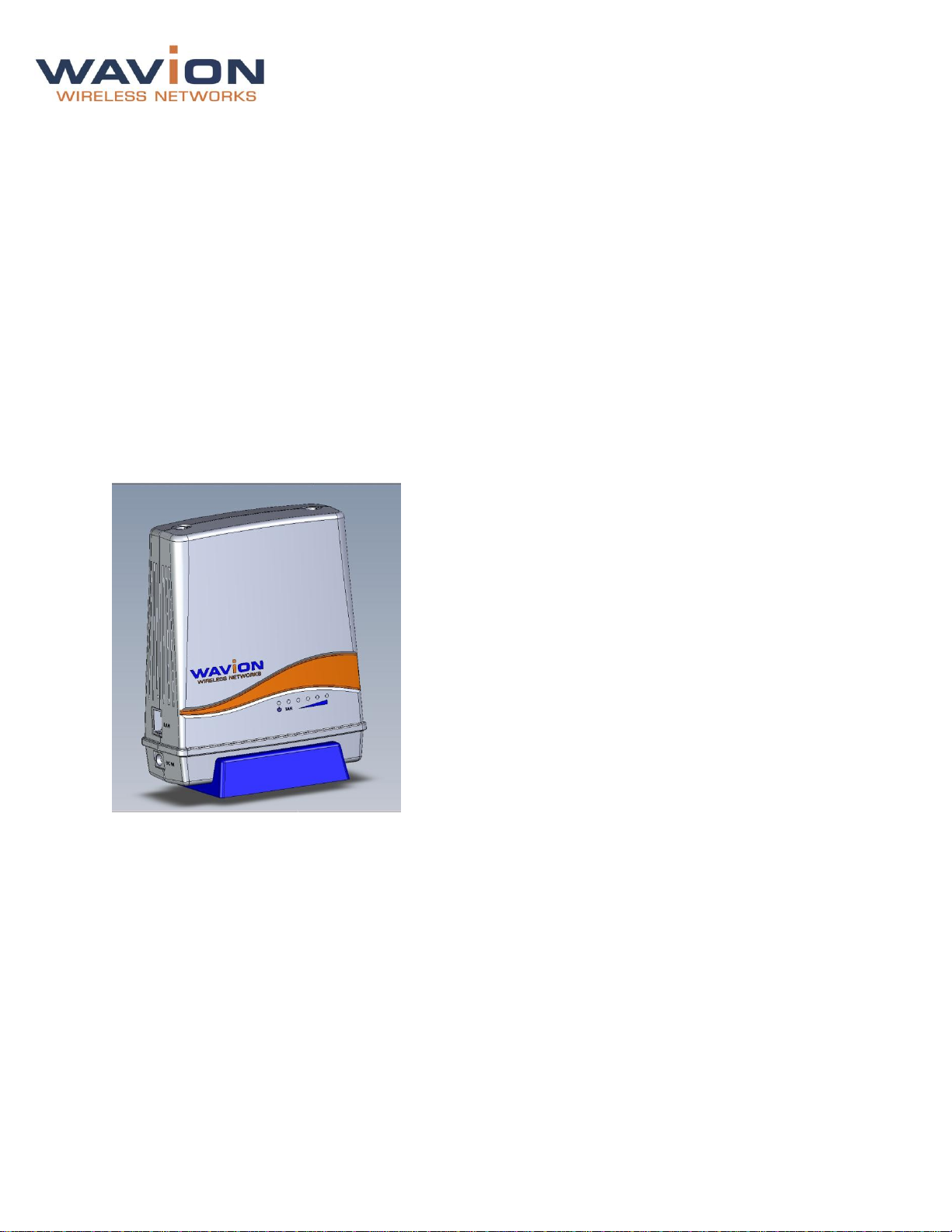
This document describes how to set-up, configure and use the WCPEn-2400-I unit. The WCPEn-2400-I is
a 2x2 MIMO IEEE 802.11b/g/n wireless indoor CPE, which supports high throughput up to 300Mbps, as
well as supporting the unique dual-zone functionality that enables it to connect as a long-range wireless
through the WAN to the outdoor WBSn base station, and repeat the signal to the LAN.
1.1 Key Features
WCPEn-2400-I key features are presented below:
Wireless 802.11n technology
Two way Beamforming with 2x2 MIMO and 2 data-streams
Four operational modes
Data Rate up to 300Mbps
High Tx power
WMM & QoS
Desktop and Window mounting options kit
WCPEn 1.0 User Guide Page - 4 -
2. Installation
This document is intended to help you set up and configure the WCPEn-2400-I.
2.1 Package Contents
The following checklist covers all the procedures and equipment that you need to acquire and assemble,
prior to beginning the installation and configuration procedures. Ensure that you check this list carefully,
before beginning any of the procedures described later in this Guide.
1x WCPEn-2400-I unit
1x WCPEn-2400-I unit base
2x 4dBi antennas
Power adapter
Windows mounting kit
CD
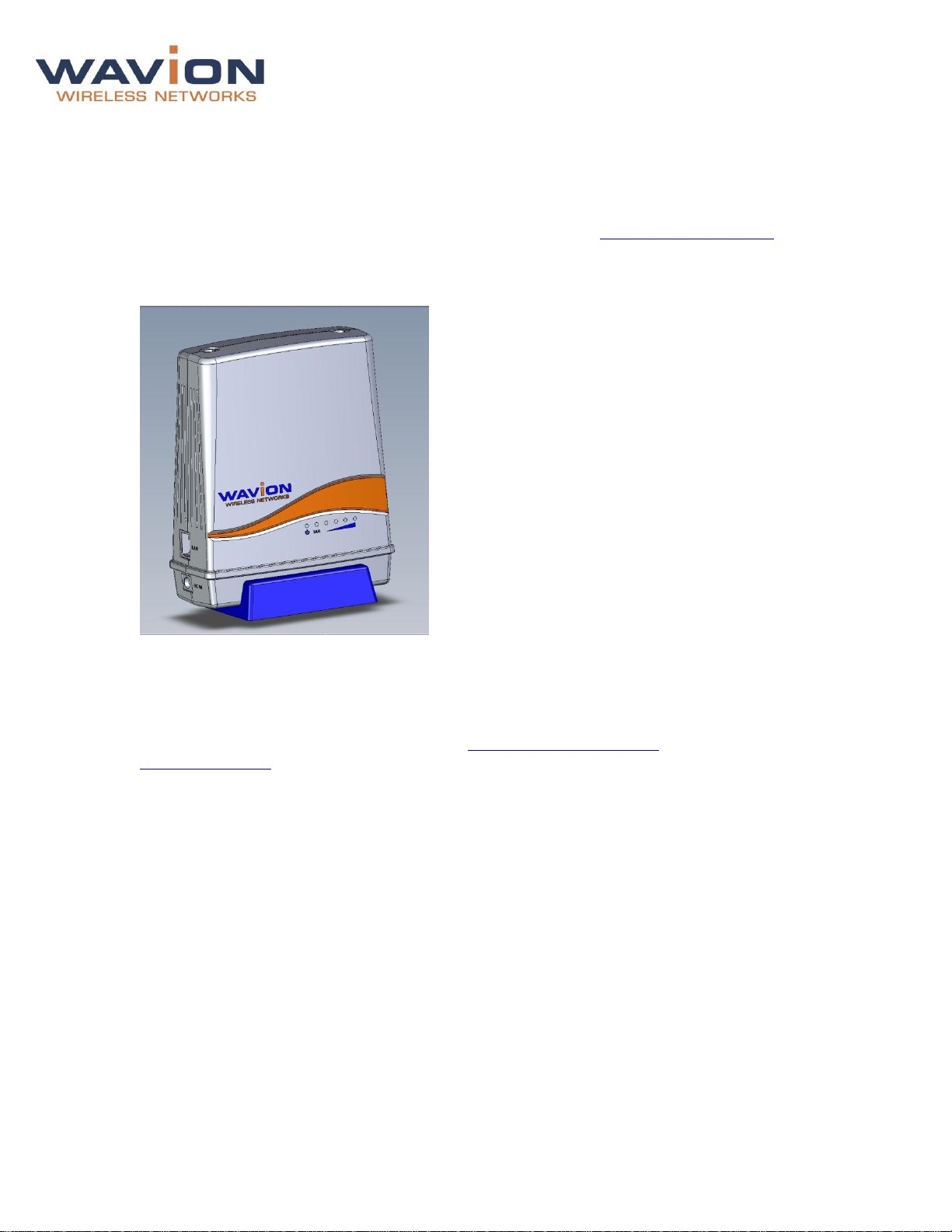
2.2 Product Layout
The image above represents the WCPEn-2400-I. The LAN and DC ports are located on the side of the
unit, and LEDs that indicate the Power, LAN and the signal strength are located on the front.
WCPEn 1.0 User Guide Page - 5 -
2.3 Installation and Set-up
The following section describes the installation and configuration procedures for the WCPEn-2400-I CPE.
2.3.1 Installing the WCPEn-2400-I
Prior to performing the procedures described in this section, ensure that you have read all the
information, and followed all instructions and safety precautions in the Pre-Installation Checklist.
WCPEn-2400-I setup
1. Insert the WCPEn-2400-I unit into the blue base stand.
2. Connect both antennas to the WCPE-2400-I unit.
3. Connect WCPEn-2400-I to a power source, using the power supply unit. The power LED switches on.
4. Connect WCPEn-2400-I to your PC, using a network cable. The LAN LED switches on.
The WCPEn-2400-I is now setup and ready to be used.
You should now proceed to the section entitled Connecting Power and Data, and after that go to
Basic Configuration in Chapter 3.
WCPEn 1.0 User Guide Page - 6 -
 Loading...