

Wavion WBSn-2400 Quick Start Manual

WBSn-2400
Outdoor Wi-Fi Base Station
Quick Start Guide

FCC Notice to Users and Operators
This equipment has been tested and found to comp ly with the limits for a Class B digital device, purs uant to Part 15 of the FC C Rules.
These limits are designed to provide reasonable protectio n against harmful interference when the equ ipment is operated i n a
commercial environment. This equipment generates, uses, and can radiate radio frequency energy and, if not installed and used in
accordance with the instruction manual, may cause harmful interference to radio communications. Operation of this equipment in a
residential area is likely to cause harmful interference, in which case the user will be required to correct the interference at his own
expense. If this equipment does cause interference to radio or television reception, which can be determined by turning the equipment
off and on, the user is encouraged to correct the interference by using one of the following measures:
• Reorient or relocate the receiving antenna.
• Increase separation between the equipment and receiver.
• Connect the equipment to an outlet on a circuit different from that to which the receiver is connected.
• Consult the dealer or an experienced radio/TV technician.
Changes or modifications to this unit not expressly approved by the party responsible for compliance could void the user’s authority to
operate the equipment.
Note: This device complies with part 15 of the FCC Rules. Operation is subject to the fo llo wing two condit ions: (1) This device may not
cause harmful interference, and (2) this device must accept any interference received, including interference that may cause undesired
operation.
R&TTE Compliance Statement
This equipment (ETSI-models only) com plies with al l th e r equirements of DIRECTIVE 19 99/5/CE OF THE EUROPEAN PARLIAMEN T A ND
THE COUNCIL of March 9, 1999 on radio equipment and telecommunication terminal Equipment and the mutual recognition of their
conformity (R&TTE).
Copyright © Wavion Wireless Networks 2011
Contents
Introduction ...................................................................................................... 3
WBSn-2400 Pre-Installation Checklist ............................................................... 3
Installation and Set-up ...................................................................................... 8
Installing the WBSn-2400-S ba se st ation...................................................................... 8
Wind Loading Considerations ................................................................................... 9
Connecting Power and DATA ................................................................................... 9
Accessing the Wav ion Management Interface............................................................. 10
Automatic Ch an n el S elect ion sc reen .......................................................................... 11
Further Configuration Features .................................................................................. 11
IP Management ........................................................................................................ 11
Management VLAN ............................................................................................... 12
Setting Up Your Base Station .................................................................................... 12
Virtual AP (VAP).................................................................................................... 12
Authentication Combinations ................................................................................. 13
Encryption Methods .............................................................................................. 14
Radio configuration (basic) .................................................................................... 14
VLAN configuration ............................................................................................... 14
QoS (Quality of Service) P ac ket Priority .................................................................. 15
Wireless Associat ions ............................................................................................ 15
ACS (online, Of f line) ............................................................................................. 16
Glossary ........................................................................................................... 17
WBSn-2400 Quick Start Guide Page 3
Introduction
This document is intended to help you set up and configure your WBSn-2400-O or WBSn-2400-S base
station, using the online Setup wizard.
Note: Throughout this document, unless specified otherwise, the use of the product name WBSn-2400
refers to both the WBSn-2400-O and WBSn-2400-S base stations.
WBSn-2400 Pre-Installation Checklist
The following checklist covers all the procedures and equipment that you need to acquire and assemble,
prior to beginning the installation and configuration procedures. Ensure that you check this list carefully,
before beginning any of the procedures described later in this Guide.
Warning
Only experienced installation professionals who are familiar with local building and safety codes
and, whe rever applicable, are li cen s ed by the a ppropria t e g ov ern m e nt re g u la to ry authori tie s
should install outdoor units and antennas.
Failure to comply with this may void the WBSn-2400 product warranty and may consequently
expose the end user or Service Provider to legal and financial liabilities.
Wavion an d its reselle rs or distributors are n ot lia ble for injur y , damage or reg ul a t ion vi o lat ions
associated with the installation of Outdoor Units or antennas
Check contents of package
WBSn-2400-O
• WBSn-2400-O base station unit (Omni)
• PoE injector unit
• 3 antennas
• Post-clamp
• Two steel bands
• 4 screws, each with attached spring and flat washers
• Iron security cable
• Waterproof sealing tape for IP67 (band to sealing rubber)
• Plastic cap and cap cover
WBSn-2400-S
• WBSn-2400-S unit (Sector)
• PoE injector unit
• Post-clamp
• Two steel bands
• 4 screws, each with attached spring and flat washers
• Iron security cable
• Plastic cap and cap cover
Warning
• The WBSn-2400 should only be installed using the antennas provided as
part of the original package.
• Ensure that the USB port on the base station unit is properly sealed.
WBSn-2400 Quick Start Guide Page 4
Additional equipment and tool s required for inst a llat ion
• Ethernet cable (outdoor CAT5e 4-pair data cable, with RJ45 connectors)
Note: Maximum cable length -- 100 meters
• Ground cable
• Portable PC
• Lightning protection
• 1”-6” diameter pole (on which to mount the unit)
Ensure a safe and secure environme nt
Warning
Connect the PoE injector to the unit using only a straight Ethernet cable.
Do not use crossed cables between the PoE injector and the unit!
Follow these guidelines to
ensure safe operation of the
WBSn-2400 base station:
• Do not touch or move the antennas while the unit is transmitting or
receiving.
• Make sure the antennas are connected when operating the radio or
attempting to transmit data, otherwise, the radio may be damaged.
• Do not hold the antenna close to or touching any exposed parts of the
body, especially the face or eyes, while transmitting.
• The use of wireless devices on airplanes is governed by the Federal
Aviation Administration (FAA). (US only)
• The use of wireless devices in hazardous locations is limited to the
constraints posed by the safety directors of such environments.
• The use of wireless devices in hospitals is restricted to the limits set forth
by each hospital.
• Do not operate a portable transmitter near unshielded blasting caps or in
an explosive environment.
• The Wavion WBSn-2400 must be used only with Wavion-approved
components and antennas.
Note:
The Federal Communications Commission (FCC) with its action in ET Docket 96-8 has adopted a safety
standard for human exposure to RF electromagnetic energy emitted by FCC certified equipment. Proper
operation of the Wavion WBSn-2400 according to the instructions found in this manual, results in user
exposure that is substantially below the FCC recommended limits.
To ensure optima l p er for m ance, select the location for t he equipment using the following
guidelines:
• The antenna should be directed towards the area intended to be covered, with maximum possible lines
of sight for client locations. Generally speaking, the higher the placement of the antenna, the better the
link quality ac hievable. For WBSn-2400-S, the coverage zone is 120° wide.
• The location of the unit should enable easy access for installation and testing.
• When installing in locations where other devices exist that operate in the same frequency range, ensure
that recommended distances are adhered to.
• The ideal height at which a base station should be installed is 2 meters above the rooftops of the
buildings within the coverage zone.
• The omni-directional unit should be installed at the highest point of a metal pole. This is to ensure that
there is no interference caused by the close proximity of the unit to the metal. Where this is not
possible, the unit should be kept at least 1 meter from the metal pole.
• Keeping the maximum distance possible from a n RF radiating source is recommended.
WBSn-2400 Quick Start Guide Page 5
Preparing the installat ion site
Only experienced installation professionals who are familiar with local building and safety codes and are
licensed, wherever applicable, by the appropriate government regulatory authorities, shou ld install ou tdoor
units and antennas.
Warnings
Do not modify the construction of this product. Modifying the operating
frequency or enhancing the transmit output power through the use of
external amplifiers or other equipment is illegal.
This device is for outdoor or indoor use on the condition that oper ation of
this device causes no harmful interference to authorized radio stations. This
device shall not influence aircraft security and/or interfere with legal
communications. If this device is found to cause interference, the operator of
this equipment shall cease operating this device immediately.
How to prepar e the site:
• Determine the existence of potential posts or poles to which a base
station could be attached. Consider the axis of the post, its placement,
and whether extenders are required.
• Follow the appropriate electrical and building codes to ensure safe an d
durable wiring.
• The length of the Ethernet cable connecting the unit to the network
device (PC, switch, router, and so on) should not exceed 100 meters.
There is no limitation on the length of the cable connecting the PoE to
the unit, as long as the combined length of the cables connecting the
network device to the PoE and the PoE to the unit does not exce ed 100
meters.
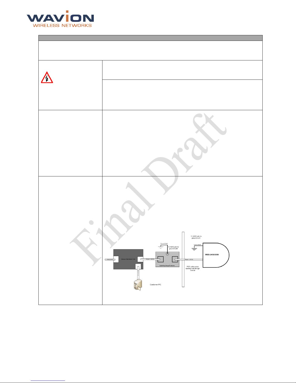
Grounding best practices,
using a data protection
device
1. Position the protection device as close to the building entrance as
possible.
2. Attach a 10 AWG grounding cable to the ground point on the data
protection device.
3. Attach the other end of the grounding cable to the grounding bar of the
building.
Grounding indoors injector by Network Protection Unit
WBSn-2400 Quick Start Guide Page 6
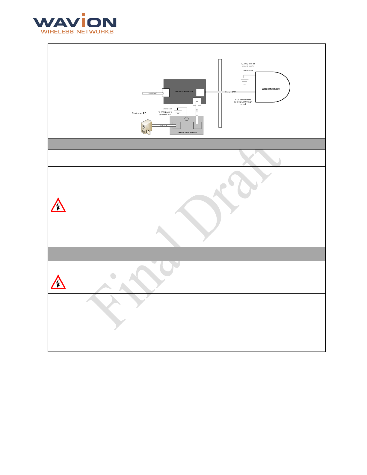
Grounding best practices,
using a data protection
device (continued)
Grounding outdoors injector by Network Protection Unit
Connecting Ant ennas (for WBSn-2400-O only)
Important note: The antennas should only be connected once the installation procedure has been
successfully completed.
How to connect the
antennas:
Screw each of the three antennas into the three N-type connectors on the
WBSn-2400-O base station unit.
Warnings
• In order for the WBSn-2400-O to work properly, all three antennas must
be connected.
• Only connect the unit to the power supply once all the antennas are
connected.
• Use caution when connecting the antennas. Undue haste can damage
the unit.
• Do not screw in the antenna when holding its top section, or you may
damage the antenna.
Antenna Sealing
The following procedure describes how to correc tly seal the antennas against moisture.
Caution
• It is important to carefully read this procedure and perform all the steps,
to ensure maximal moisture protection.
• Use high quality sealing material to ensure IP-67 compliant protection
against dust and water.
How to seal the
antennas:
1. After the antenna is connected, use the supplied isolation tape to cover
the N-Type connectors and the lower part of the antennas.
2. Cut 18 cm of the attached splicing tape and ensure that the sticky side
of the tape is exposed.
3. Stretch and wrap the tape in an even, half-lapping manner around the
antenna and N-Type connector. Cover this with a layer of vinyl plastic
tape.
 Loading...