

Wavion WBS-2400, WBS-2400-SCT User Manual

WBS-2400 and WBS-2400-SCT
User Manual
SW version 4.0
March 2010

Rev 4.0 User Manual 2
Copyright Notice
©2006, 2007, 2008, 2009 Wavion, Inc. All rights reserved. Wavion is a registered trademark of
Wavion in the United States and certain other jurisdictions. Specifications are subject to change
without notice.
FCC Notice to Users and Operators
This equipment has been tested and found to comply with the limits for a Class B digital device,
pursuant to Part 15 of the FCC Rules. These limits are designed to provide reasonable
protection against harmful interference when the equipment is operated in a commercial
environment. This equipment generates, uses, and can radiate radio frequency energy and, if
not installed and used in accordance with the instruction manual, may cause harmful
interference to radio communications. Operation of this equipment in a residential area is likely
to cause harmful interference, in which case the user will be required to correct the interference
at his own expense. If this equipment does cause interference to radio or television reception,
which can be determined by turning the equipment off and on, the user is encouraged to
correct the interference by using one of the following measures:
• Reorient or relocate the receiving antenna.
• Increase separation between the equipment and receiver.
• Connect the equipment to an outlet on a circuit different from that to which the receiver is
connected.
• Consult the dealer or an experienced radio/TV technician.
This Part 15 radio device operates on a non-interference basis with other devices operating at
this frequency. Any changes or modification to said product not expressly approved by Wavion
could void the user's authority to operate this device.
W
ARNING: It is illegal to modify the construction of this product. Modifying the
operating frequency or enhancing the transmit output power through the use of
external amplifiers or other equipment is specifically disallowed by the
“Telecommunications Act.”
W
ARNING
:
This device is for outdoor use with conditions that no harmful interference
to authorized radio stations results from the operation of this device. This device shall not
influence aircraft security and/or interfere with legal communications as defined in the
“Telecommunications Act.” If this device is found to cause interference, the operator of this
equipment shall cease operating this device immediately until no interference is achieved.
N
OTE
: This device must be installed by a trained professional, value added reseller or systems
integrator who is familiar with RF planning issues and the regulatory limits in the United States of
America.

3 Wavion
READ THIS FIRST!
Important Safety Instructions
C
AUTION: The exclamation point within a triangle is intended to alert the user to the
presence of important operating and maintenance (servicing) instructions in the
literature accompanying the product.
W
ARNING: The lightning flash with an arrowhead symbol within a triangle is intended
to alert the user to the presence of uninsulated dangerous voltage within the
product’s enclosure that may be of sufficient magnitude to constitute a risk of electric
shock to persons.
C
AUTION: Read and save these instructions. Heed all warnings. Follow all
instructions.
C
AUTION: Do not defeat the safety purpose of the grounding. Only use attachments/
accessories specified by the manufacturer.
C
AUTION
: Refer all servicing to qualified service personnel. Servicing is
required
when the apparatus has been damaged in any way. For example, if the
power-supply cord or plug is damaged, liquid has been spilled on the
apparatus, objects have fallen into the apparatus, the apparatus has been
exposed to rain or moisture, it does not operate normally, or has been
dropped.
W
ARNING: There is a risk of personal injury or death if the WBS-2400 antennas
come near electric power lines. Carefully read and follow all instructions in this
manual. By nature of the installation, you may be exposed to hazardous
environments and high voltage. Use caution when installing the outdoor system.
W
ARNING: This apparatus must be connected to earth ground.
W
ARNING: Do not open the unit. There is a risk of electric shock inside.
C
AUTION: You are cautioned that any change or modification not expressly approved
in this manual could void your authority to operate this equipment.

Rev 4.0 User Manual 4
C
AUTION
:
There are no user-serviceable parts inside. All service must be performed
by qualified personnel.
C
AUTION: The RJ45 connectors of your Wavion WBS-2400 may source DC power on
pins 4,5 and 7,8. The IEEE 802.3 standards allow for pins 4,5 and 7,8 to be used for
Power Over Ethernet. Some products may be incompatible with the Wavion Power
Over Ethernet capability. If such problems occur, make sure that the unit is
configured with the Power Over Ethernet capability set to Off (default setting). If
problems persist, use Ethernet cables that have no connections to the unused pins
4,5 and 7,8.
C
AUTION: The Wavion WBS-2400 and WBS-2400-SCT can be installed in wet,
outdoor locations. Make sure closure caps are installed and all cable connections are
securely fastened and waterproofed.
C
AUTION: The Wavion WBS-2400 can only be used with approved antennas.

5 Wavion
About This Manual
The following describes configuration of the WBS-2400 and WBS-2400-SCT. It is intended for
use by network engineers and administrators charged with setting up and administering Wavion
wireless networks. This manual contains the following:
•
Chapter 1: Viewing the System Status
: Explains the Home page with its summary of the
system status.
•
Chapter 2: Managing the System Configuration
: Explains how to configure the system,
upgrade the software version and install SDMA feature. Contains detailed information about
the system’s modules.
•
Chapter 3: Managing Network Interfaces
: Allows configuration of the Ethernet and wireless
interfaces.
• Chapter 4: SSID and VLAN Configuration: Explains how to configure BSSID and VLAN,
contains detailed information and the relationship between them.
•
Chapter 5: Viewing Associated Stations
: Lists the associated stations and their
configuration into VLAN.
•
Chapter 6: Managing System and Station Security
: Explains how to configure new users,
passwords, SNMP and HTTPS configuration.
•
Chapter 7: Viewing Events
: Explains how to view and configure the system event logs.
•
Chapter 8: Upgrading the System Software
: Provides detailed instructions for upgrading
the system software version.
•
Chapter 9: Appendix: Troubleshooting
: Provides tips on dealing with possible questions you
may have in working with the WBS-2400 and WBS-2400-SCT.
Related documents
The following titles are Wavion Reference documents:
• Installation Guide
• Firmware Upgrade procedure

Contents
Ch ap te r 1
Viewing the System Status .......................................................................... 10
Logging in........................................................................................................................... 10
Logging out ........................................................................................................................10
StartUp wizard ...................................................................................................................10
Viewing the Home Page................................................................................................... 13
To view the Home page .........................................................................................13
Ch ap te r 2
Managing the System Configuration .......................................................... 15
Viewing the System Configuration .................................................................................15
Saving Changes........................................................................................................19
Managing System and Software Configurations ..........................................................19
Performing Software Upgrades .............................................................................19
Managing the System Configuration.....................................................................21
Exporting the Current Startup Configuration File ............................................... 22
Importing a New System Configuration File........................................................ 23
Restore to the Factory Default Configuration File .............................................. 23
Features Licensing- SDMA......................................................................................23
Installing the SDMA feature ...................................................................................24
Viewing the System Hardware Components.................................................................26
Debug Interface ................................................................................................................27
Ch ap te r 3
Managing Network Interfaces ..................................................................... 30
Viewing the Network Interfaces Summary ...................................................................30
Managing the Ethernet Interface....................................................................................32
Managing the Wireless Interface.................................................................................... 33
Setting the Operational Channel ...........................................................................36
Setting the Transmission Power............................................................................37
Selecting the Interference Handling Mode ..........................................................37
Saving Changes........................................................................................................39
Wireless Activity.......................................................................................................39
Automatic Channel Selection .................................................................................42
Backhaul .............................................................................................................................45
Bridge..................................................................................................................................57
Ch ap te r 4
SSID and VLAN configuration...................................................................... 61
IEEE 802.11 and WBS-2400 Security Concepts ...........................................................61
Security Modes: Authentication and Encryption Methods .................................61
Authentication Combinations .................................................................................62
Encryption Methods.................................................................................................62
QoS Packets Priority .........................................................................................................63
Configuring WEP Security....................................................................................... 72
Configuring WPA Security.......................................................................................74
Configuring RADIUS Server Parameters ..............................................................74

7 Wavion
Configuring WPA2 Security.....................................................................................75
Configuring RADIUS Server Parameters...............................................................75
VLAN Configuration ...........................................................................................................76
Tagging VLAN ...........................................................................................................76
Configuring VLAN .....................................................................................................77
Configuring Multiple VLANS per SSID ...................................................................79
Management VLAN...................................................................................................81
Ch ap te r 5
Viewing Associated Stations.........................................................................82
Viewing Stations .......................................................................................................82
Viewing Associated Stations.............................................................................................83
Viewing Specific Stations ........................................................................................84
MAC Filtering ......................................................................................................................90
Ch ap te r 6
Managing System and Station Security ......................................................92
Viewing the Security Page................................................................................................92
Viewing the Management Configuration Page ..............................................................93
HTTP Configuration..................................................................................................96
Viewing the Authentication Pages...................................................................................96
Ch ap te r 7
Viewing Events ...............................................................................................99
Viewing the Most Recent Events.....................................................................................99
Viewing the Full Event Log .................................................................................. 100
Navigating the Event Log..................................................................................... 101
Configuring Event Logs ........................................................................................ 102
Ch ap te r 8
Upgrading the System Software............................................................... 105
Prerequisites.................................................................................................................... 105
Tools and data required for upgrade:................................................................ 105
Firmware Upgrade Procedure .............................................................................106
Roll back procedure .............................................................................................. 111
To return to the system default software version ...........................................111
Ch ap te r 9
Appendix: Troubleshooting........................................................................ 113
Basic Troubleshooting .......................................................................................... 113
LED Description ..................................................................................................... 114
Rev 4.0 User Manual 8
Introduction
Wavion is glad to have the opportunity to offer the WBS2400 family of products as the best wireless
coverage solution for your project requirements. Wavion’s next-generation base stations, referred to as
spatially adaptive WiFi Base Stations, are designed specifically to address shortcomings in current outdoor
access points for rural and metro WiFi applications. Wavion’s powerful digital beam-forming and space
division multiple access (SDMA) technologies - the next-generation of multiple-antenna technology - address
limitations in coverage, penetration, and capacity of existing WiFi technology, and provide significant
performance and cost advantages compared to current conventional WiFi solutions.
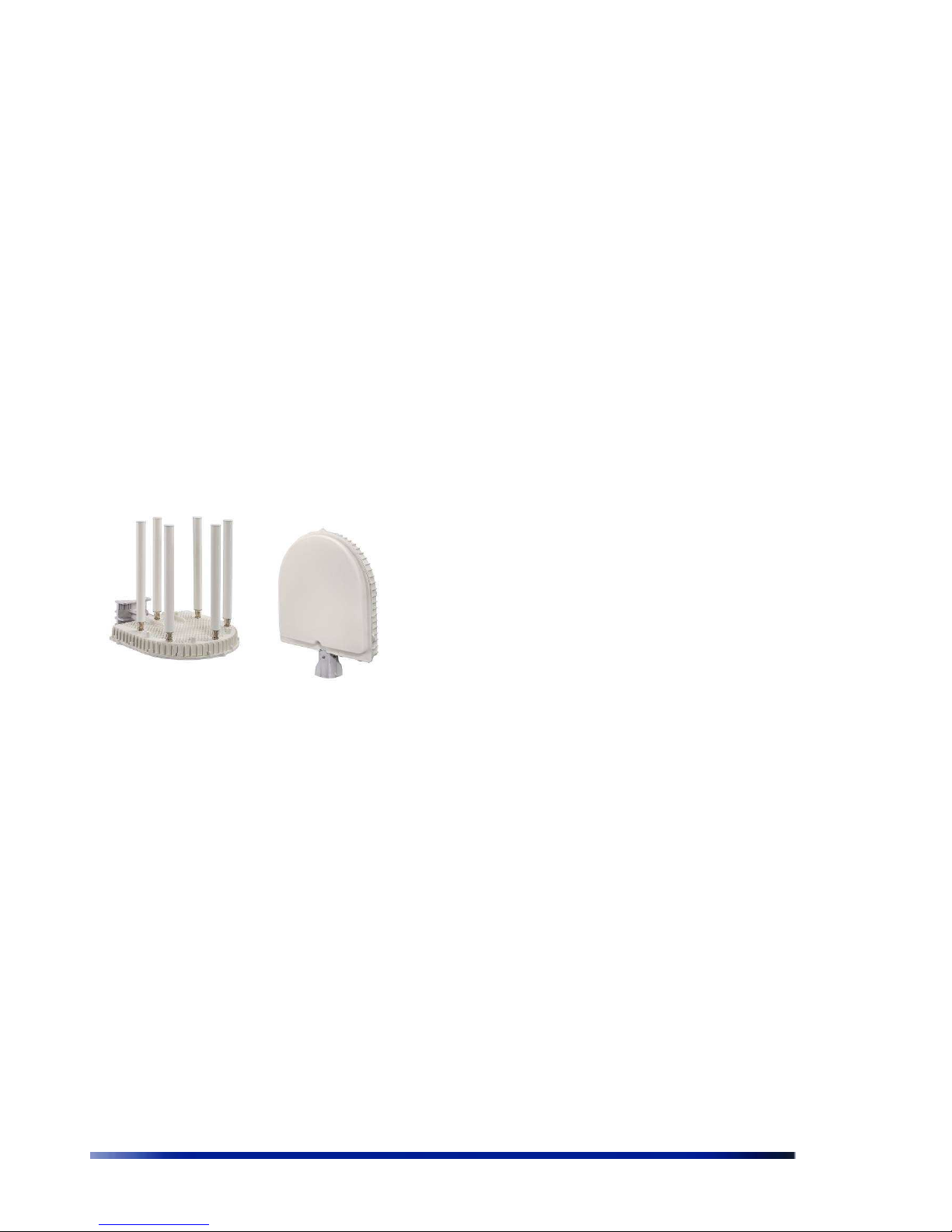
The WBS2400 and WBS-2400-SCT Base Stations
WBS2400 Key Benefits:
• Exceptional coverage, range, throughput,
network capacity, scalability, and reliability
• Excellent building and wall penetration
• Uniform coverage and enhanced non-lineof-sight operation
• High interference resilience
• Enhanced mobility support
• Simple deployment and low infrastructure
and operating costs
• Full compatibility with standard 802.11b/g
clients
9 Wavion
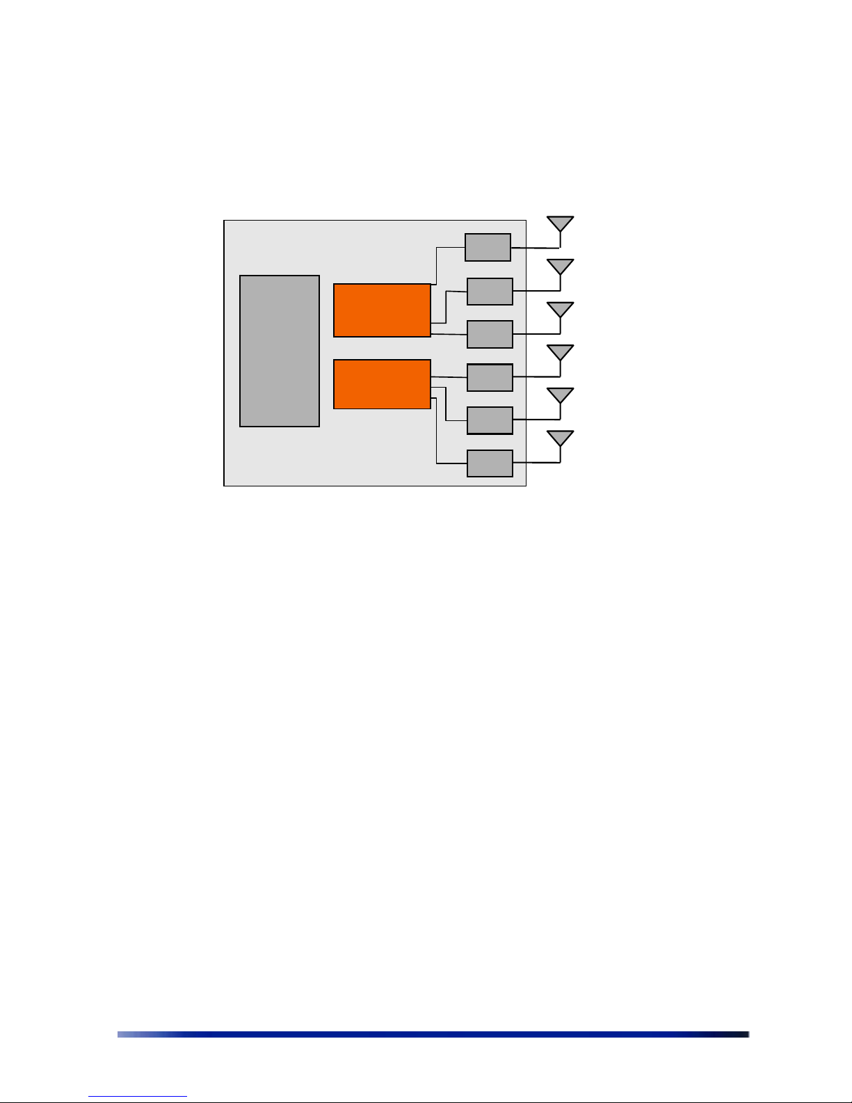
Figure 1.1
: Shows the relationship between the WBS-2400 hardware modules.
Figure 1.1 HW Block diagram
• CPU – Control and synchronize the whole system performance
• Wavion ASIC - Smart RF technology resides in the ASIC and software
• WBS-2400- Six RF modules and Antennas - Standard off-the-shelf components and antennas
• WBS-2400-SCT -Three RF modules and Antennas- Standard off-the-shelf components
• Wired Data – 10/100 Base-T Ethernet terminals with POE in or optional output.
RF
RF
RF
RF
RF
Wavion
ASIC
CPU
Wavion
ASIC
RF
Viewing the System Status
Chapter 1
Viewing the System Status
The Home page shows a summary of status data of the system. From within this page, you can
quickly link from fields to other related pages for more information.
Logging in
The default IP address of the unit is IP: 192.168.1.1 and mask: 255.255.255.0.
To log-in, type “admin” in the username field, and “admin” in the password field.
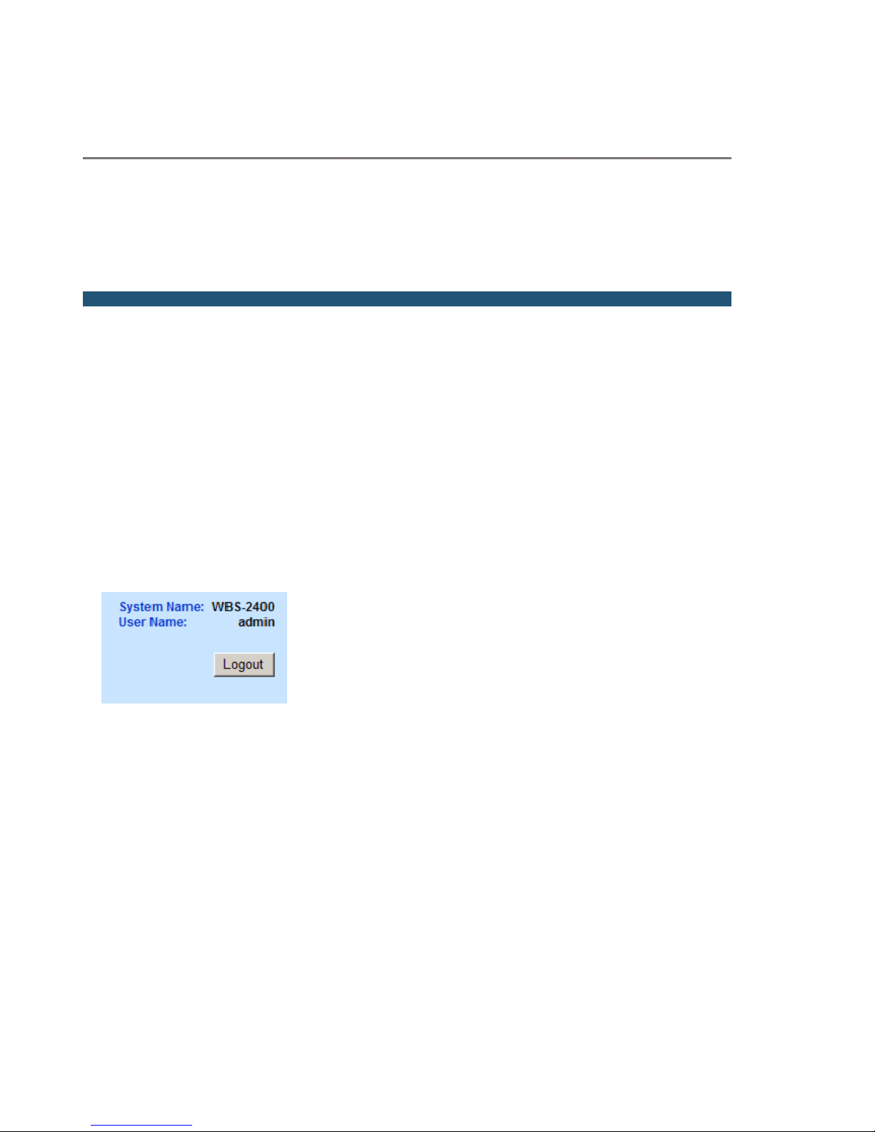
Logging out
Is possible to log-out at any time by pressing the “Logout” button on the upper right-hand side
of the screen.
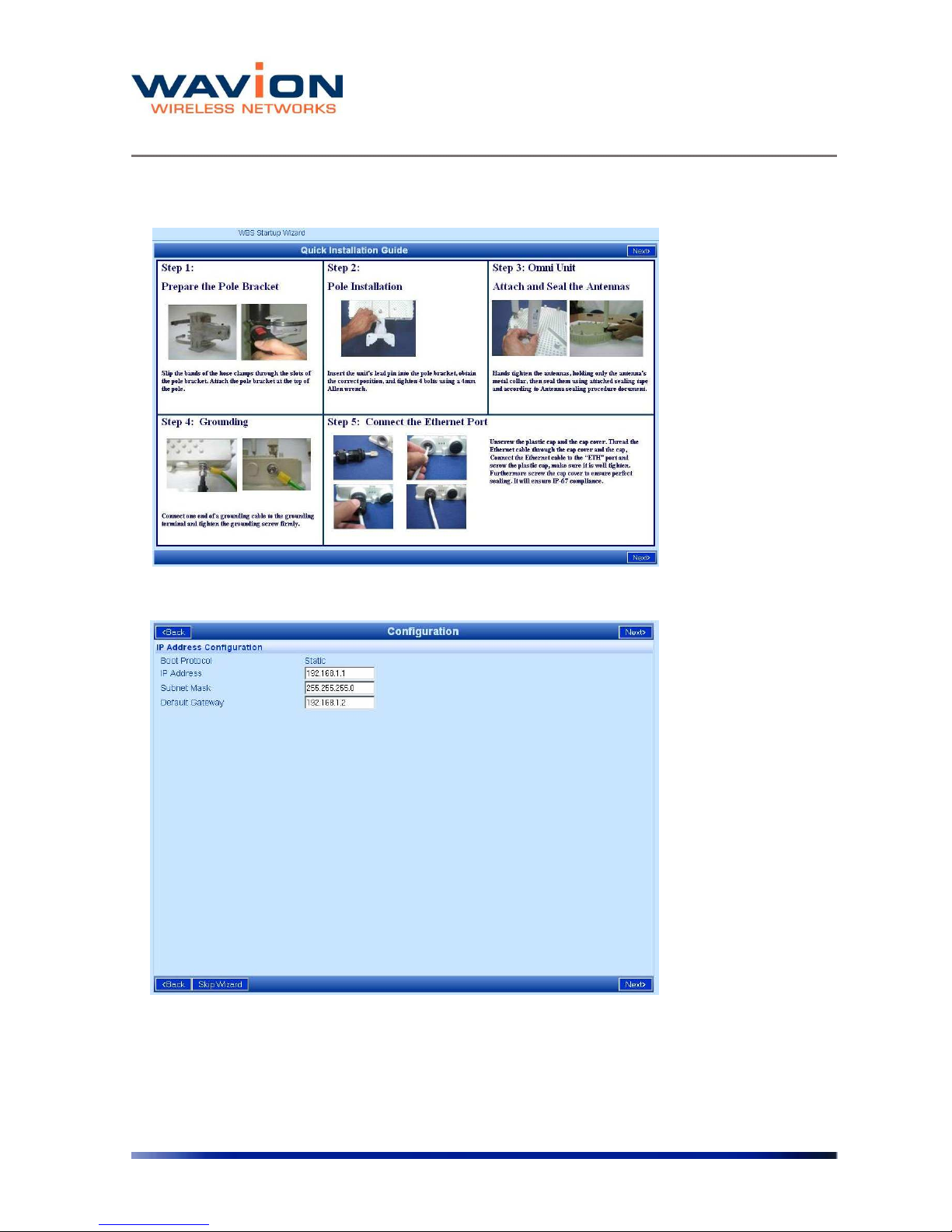
StartUp wizard
Upon login, the start-up wizard appears. This wizard is composed of 3 pages:
◊ Quick Installation guide
◊ IP Address Configuration
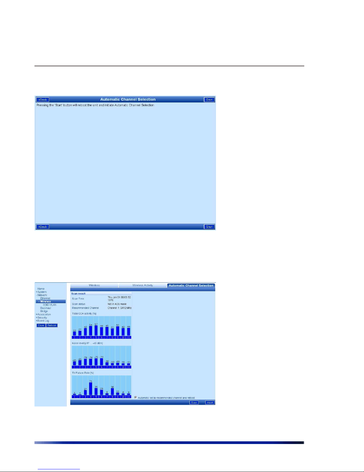
◊ Automatic Channel Selection
Moving to one page to the other is done by pressing the “Next” button. From the “IP setting”
page is possible to skip the Wizard. The wizard stops after the ACS. The page shown is the ACS
results, where is possible to check the status of the spectrum around the WBS area.
The wizard will be activated every login. To deactivate the wizard go to the “System “ menu
page and disable the Wizard through the “Startup Wizard” drop-down list at the bottom of the
page.
Viewing the System Status
11 Wavion
Figure 1.2 Quick Installation Guide
Figure 1.3 IP Address Configuration
You can skip the Wizard in this page by pressing the “Skip Wizard” button.
Viewing the System Status
Rev 4.0 User Manual 12
Figure 1.4 Automatic Channel Selection
After pressing “Start” a channel scanning will be performed.
The last page of the wizard is the ACS results. From this page starts the normal functionality of
the GUI.
Figure 1.5 Automatic Channel Selection
Viewing the System Status
13 Wavion
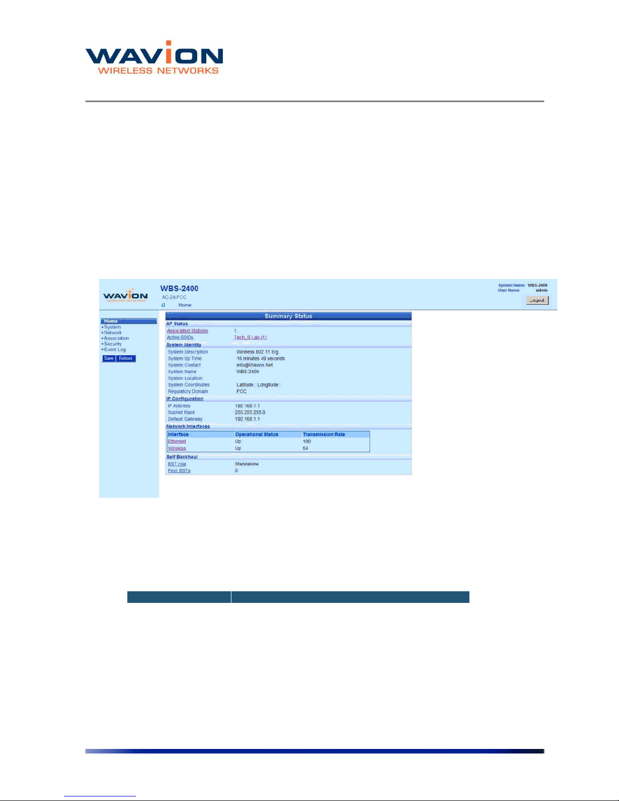
Viewing the Home Page
To view the Home page
• Click Home.
The Summary Status page is displayed.
Figure 1.6 Home: Summary Status Page
The following fields appear on the Summary Status page:
Table 1.1 Home: Summary Status Page
Field Description
BST Status
Associated Stations Links to Associated Stations page
Active SSID Service Set Identifier; links to Editing SSID page

Viewing the System Status
Rev 4.0 User Manual 14
Table 1.1 Home: Summary Status Page
Field Description
System Identity Links to System Configuration page
System Description
Description of the device as written in MIB-II SysDescr
OID
System Up Time
Total time since system was switched on or last reinitialized
System Contact
Administratively-assigned email address of system
operator
System Name
Administratively-assigned name for this managed node;
the node's fully-qualified domain name.
System Location
Administratively-assigned physical location of this node
(e.g. ‘telephone closet, 3rd floor')
System Coordinate Display the unit’s Latitude and Longitude
Regulatory Domain
Display the unit regulatory domain according to
802.11d
IP Configuration Links to System Configuration page
IP Address The current IP address of the unit
Subnet Mask
The current subnet mask used to establish the
broadcast domain.
Default Gateway The current IP address of the default gateway.
Network Interfaces Links to Network Interfaces Summary page
Network Interfaces Links to interfaces configuration page
• Ethernet
• Wireless
Operational Status Up/down
Transmission Rate Maximum transmission rate on the interface in Mbps
Self Backhaul
BST role
Display current BST self backhaul configuration and link
to the configuration page
Peer BST
Display number of connected peers and link to the
connected BST page
Managing the System Configuration
Chapter 2
Managing the System Configuration
The System Configuration page displays system identification parameters like, IP information,
system location servers etc. The other system pages allow updating of the software version and
system configuration, and a view of the system components.
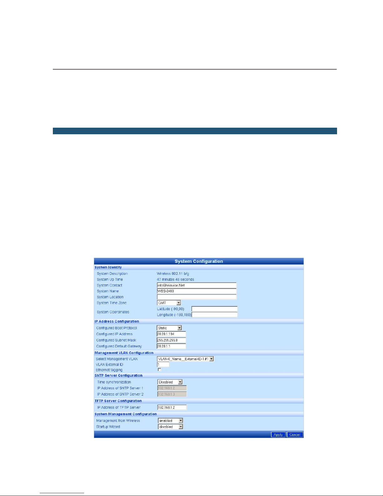
Viewing the System Configuration
To view the System Configuration page
• Click the System menu item.
The System Configuration page displays.
Figure 2.1 System Configuration Page

Managing the System Configuration
Rev 4.0 User Manual 16
The following fields appear on the System Configuration page:
Table- 2.1 System Configuration
Field Description
System Identity
System Description Description of the device as written in MIB-II SysDescr OID
System Up Time Total time since system was switched on or last re-initialized
System Contact, Name,
Location, Time Zone,
Coordinates
These parameters are for the user convenience while
observing system status via WEB or NMS
IP Address
Configuration
Configured Boot Protocol Get Static IP or from DHCP server
Configure IP Address,
Subnet Mask and Default
Gateway
Configure the unit IP parameters
Management VLAN
configuration
Select Management VLAN List of configured VLAN. Select one as the Management VLAN
VLAN External ID
VLAN ID number configured from the VLAN Switch for
Management VLAN traffic.
Ethernet tagging Enable to VLAN tag all Management traffic
SNTP Simple Network Time protocol
Time Synchronization
Disable the Time Synchronization or set the Static IP address
of the SNTP server or DHCP
IP address of SNTP
Servers
Enter the IP address of your desired SNTP servers to sync all
system messages to calendar time
Configure TFTP Server
IP Address of TFTP Server
The IP address of the default TFTP server; can be overridden
in the Software Upgrade page for a temporary SW download
System Management
Configuration
Management from
Wireless
Enable/Disable
Startup Wizard Enable/Disable the Startup Wizard

Managing the System Configuration
17 Wavion
This page contains basic static information on the system, such as contact details, and IP
addresses. Several changes are recommended on this page.
Setting System Contact Details
In the System Identity area, in the System Contact field, enter the contact email address of the
net owner.
Setting the IP Address Configuration
Change the IP address to allow the full configuration. The Current IP Address Configuration
area lists a default IP address; it is possible to perform initial testing with this address, but it is
highly recommended to change the IP address.
To change the IP address
In the IP Address Configuration section,
1. For a DHCP obtained address, select DHCP. Following a reboot, the WBS-2400 will
automatically obtain and IP address, Subnet mask, and Default Gateway from the DHCP
server.
2 To allow entry of a new IP address, select Static from the Configured Boot Protocol
dropdown list.
3 In the Configured IP Address field, enter the required IP address.
4 In the Configured Subnet Mask, enter a valid network mask.
Note: The system must be rebooted for these changes to take effect.
Setting the Management VLAN configuration
The purpose of the management VLAN is to segment the Management and the Clients data
traffic. It also provides an option for customers to keep an Open SSID for public traffic and
simultaneously manage the WBS-2400 traffic over a separate VLAN (that may be linked to a
secured SSID). The management VLAN can be selected out of the enabled VLAN list.
Note: Only one VLAN can be defined as the Management VLAN in the
WBS-2400 system.
The configuration of the Management VLAN takes effect immediately.
This means that setting the Management VLAN has to be done in 2 steps:

Managing the System Configuration
Rev 4.0 User Manual 18
1. Applying the VLAN parameters (external VLAN ID and tagging mode) using the
existing management traffic, and selecting the desired VLAN to be the Management
VLAN on the Administration page. After this stage the current wire-line connection
to the system GUI will drop.
2. Saving the parameters – using the new Management VLAN, i.e. over the tagged
VLAN.
To enable VLAN management
1. Apply the VLAN parameters (external VLAN ID and tagging mode) using the existing
management traffic or create a new VLAN ID.
2. Select the desired VLAN ID for the Management VLAN traffic.
3. Click Apply and Save
Note: The configuration of the Management VLAN takes effect
immediately. Therefore setting the Management VLAN is done over the
"old" VLAN (default is VLAN-1 untagged), while saving is done over the
"new" VLAN.
The 3rd step in "To enable VLAN management has to be done over a
different machine/ the new VLAN.
Setting the System Management Configuration
You can decide to allow system management from the Wireless Interface, or to allow
management only from the Ethernet Interface, for security purposes.
To enable or disable system management from the Wireless
Interface
In the System Management Configuration area, in the Management from Wireless field, from
the dropdown list, select enabled to allow system management from the wireless interface, or
Disabled to restrict system management to the Ethernet Interface.
To enable or disable Startup Wizard
From the dropdown list, select “Disabled” to stop performing the Startup Wizard after each
login.
Managing the System Configuration
19 Wavion
Saving Changes
Note: After making changes on this page, you must click both Apply and Save,
or the changes do not remain in effect after the next reboot.
1. Click Apply.
2. Click Save.
Managing System and Software Configurations
You can change the system startup configuration, upgrade the software version from the
system software tabs and install the SDMA feature license.
To access the system software tabs
• Click System Software from the menu, as a sub-item of the System menu item.
The system software tabs display, consisting of the Software Upgrade tab for managing the
system software version, the System Configuration tab for managing the system configuration,
and the Features Licensing tab to install/uninstall the SDMA feature.
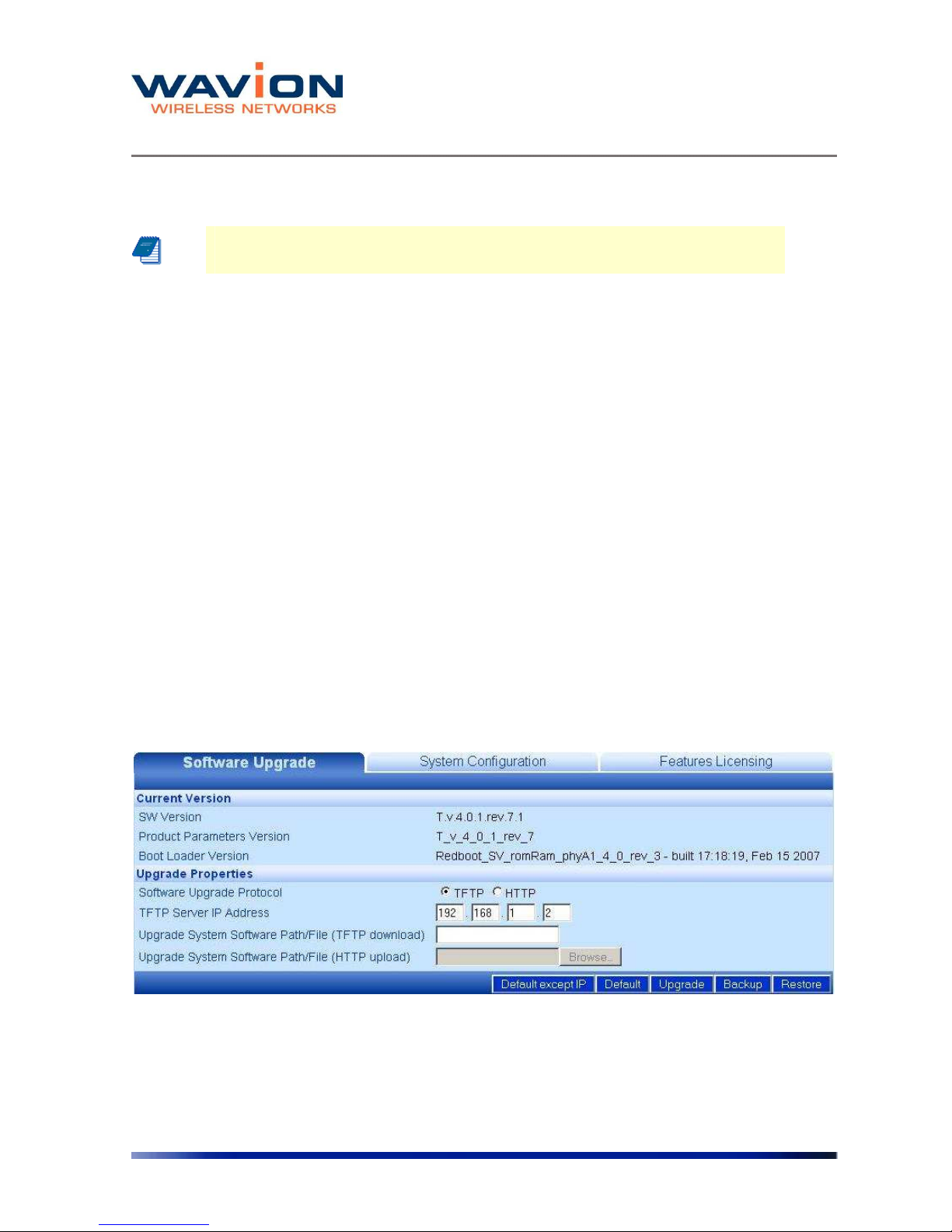
Performing Software Upgrades
The Software Upgrade tab shows details about the current software version and allows setting
properties required to install a new software version. It is also possible to return to the factory
default software, backup the current version of the software and return to a previously backed
up version of the software.
Figure 2.2 Software Upgrade Tab
Returning to the Default Software Version
You can reinstall the default software version, using one of two options:
Managing the System Configuration
Rev 4.0 User Manual 20
1. Default Except IP – In this case, the unit will lose its current setting without changing the IP
address. This option is convenient when choosing to return to default from a remote
location.
2. Default – In this case, the unit will lose its current setting and gets system defaults of IP:
192.168.1.1 and mask: 255.255.255.0
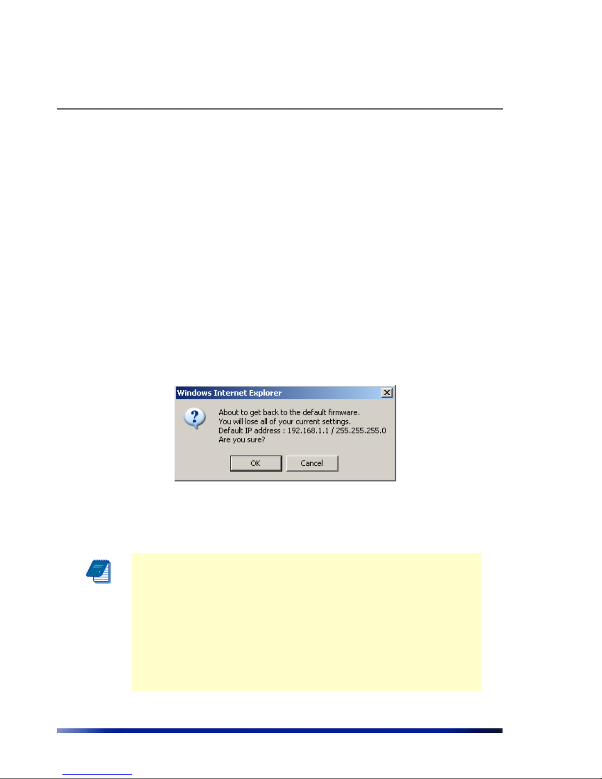
To return to the system default software version
1. Click Default or Default Except IP.
2. Click OK
A warning popup displays.
Figure 2.3 Default Popup
The system returns to the default software version and default IP and mask settings.
Note: Is possible to return to factory defaults using the reset pushbutton.
Press the button firmly until the “STATUS” LED blinks fast with red light
(around 40 seconds).
The reset button differs in location according to the WBS HW model:
◊ If your WBS has a connection box, the reset pushbutton is
located in the box.
◊ If your WBS has only ETH and TEST ports, the reset button
is located in the PoE injector next to the PoE output port.
The configuration, SW version, and SDMA license status will revert to
default.
Managing the System Configuration
21 Wavion
Upgrading the Software Version
A full description of upgrading the software version is given in upgrading the System Software
section in Chapter 7.
Backing Up the Current Software Version
You can backup the software version currently installed on the system. This can be used before
upgrading to a new version with which you do not have experience.
To back up the current version of the software
• Click Backup.
The current version of the software is saved, and can be restored to the system if necessary.
Restoring the Last Saved Software Version
If you backed up a software version before upgrading to a new one, it is possible to return to
the previous version.
To return to a previous system software version
• Click Restore.
The last backed up version of the system software is restored to the system.
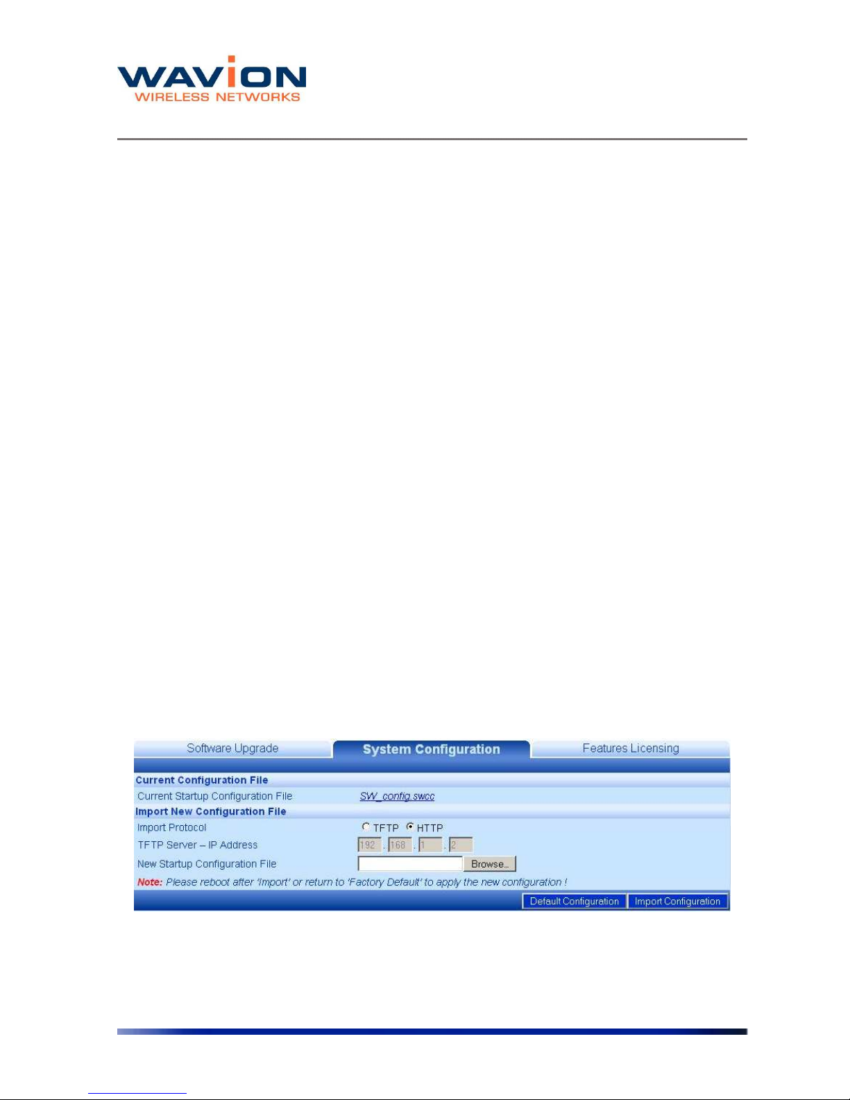
Managing the System Configuration
On the System Configuration tab you can manage current system configuration file name and
the configuration management parameters. You can also restore the factory default
configuration file, export the current system configuration file, or import a new system
configuration file.
Figure 2.4 System Configuration Tab
The following fields appear on the System Configuration tab:

Managing the System Configuration
Rev 4.0 User Manual 22
Table- 2.2 System Configuration tab
Field Description
Current
Configuration File
Current Startup
Configuration File
File currently used to configure system on startup. This field is
also used to export the current configuration file. Rightclicking on the file name allows you to save the current
Startup Configuration File on you local disk. See Exporting the
Current startup Configuration File.
Import New
Configuration File
To import a saved configuration file
Import Protocol
TFTP/HTTP
Configuration file can be imported using either TFTP or HTTP
protocols
TFTP Server - IP
Address...
IP address of the TFTP server, if, for the current downloading,
it is not the same as the default TFTP Server. Setting the
value here is only relevant for this download and does not
hold across a Reboot.
The Default TFTP Server is set in the System Configuration
page. See Viewing the system Configuration
New Startup
Configuration File
Path including the .swcc file being HTTP downloaded; select
path using the Browse button which is activated if HTTP is
selected as the import protocol
Factory Defaults
Used to restore the factory default startup configuration.
Clicking here erases the configuration file that contains all the
changes you made to the unit except the unit's IP address.
See Restore the Factory defaults
Import System
Configuration
Used to import a new startup configuration from a previously
saved file.
See Importing a New System Configuration file
You have the option of exporting the current startup configuration, importing a new startup
configuration or of restoring the factory default configuration file.
Exporting the Current Startup Configuration File
To export the current system configuration
1. Click on the name of the current software configuration.
A File Download dialog box will appear listing the Name, Type, and From IP address.
A File Download dialog box will appear listing the Name, Type, and From IP address.
Managing the System Configuration
23 Wavion
A Save As dialog box will appear.
5 Choose the save in folder, create the correct File name, and click on the Save button.
Importing a New System Configuration File
To import a new system configuration
Select the import protocol to be used, either TFTP or HTTP.
If TFTP is selected, enter the IP address of the TFTP server to be used for the download, if it is
not the default server.
In the New Startup Configuration File, click Browse and select the file location.
Click Import Startup Configuration.
Note: Do not click Save.
Reboot the system to apply the new configuration.
The new configuration files take effect.
Restore to the Factory Default Configuration File
To restore the factory default configuration file
Click Factory Defaults.
Note: This procedure erases the configuration file that contains all the
changes you made to the unit except the IP address.
Note: Do not click Save.
Reboot the system to apply the factory default configuration.
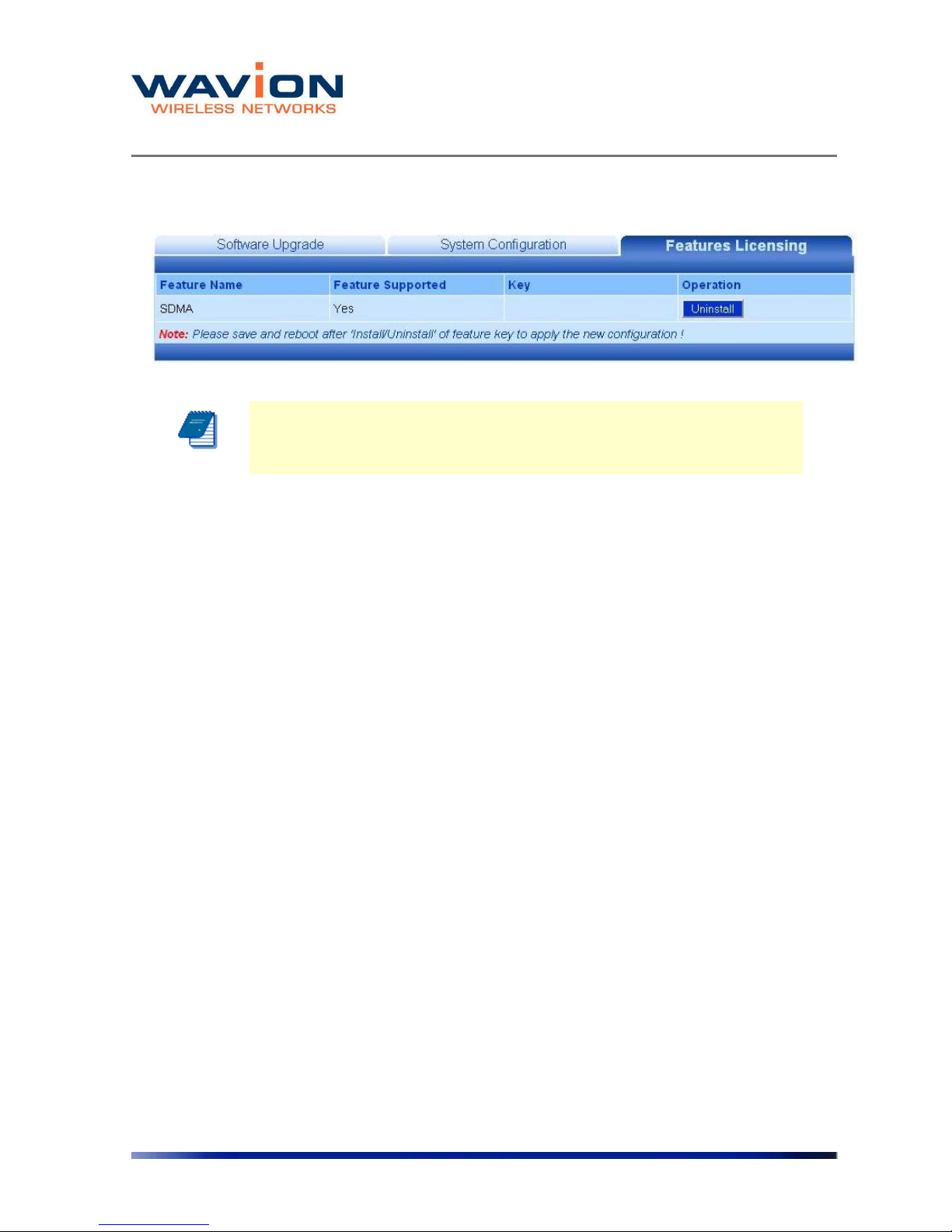
Features Licensing- SDMA
On the Features Licensing tab you can manage the installation of the SDMA feature. This
feature is managed through a one time license installation. This license is issued on a unit by
unit basis. That means that a license issued will work only with the unit the license was issued
for.
In order to get a license, please send the Tech Support Report and your company details to:
support@wavionnetworks.com
Managing the System Configuration
Rev 4.0 User Manual 24
For help creating the Tech Support Report, please refer to Debug Interface section. Please send
one Tech Support Report per each WBS-2400 where you want to enable the SDMA feature.
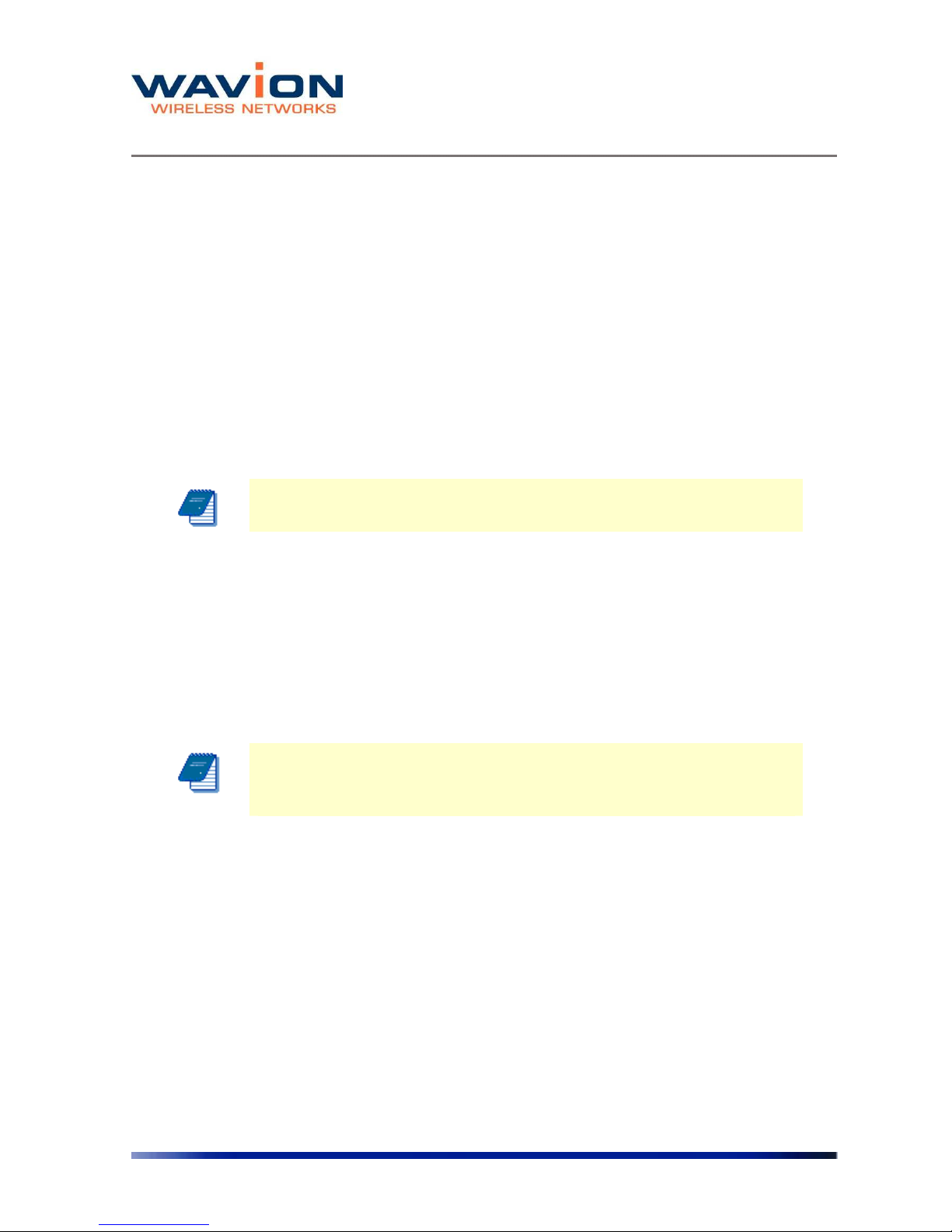
Figure 2.5 Features Licensing Tab
Installing the SDMA feature
Upon reception of the license key, type it in the “Key” field of the “License Featuring” tab.
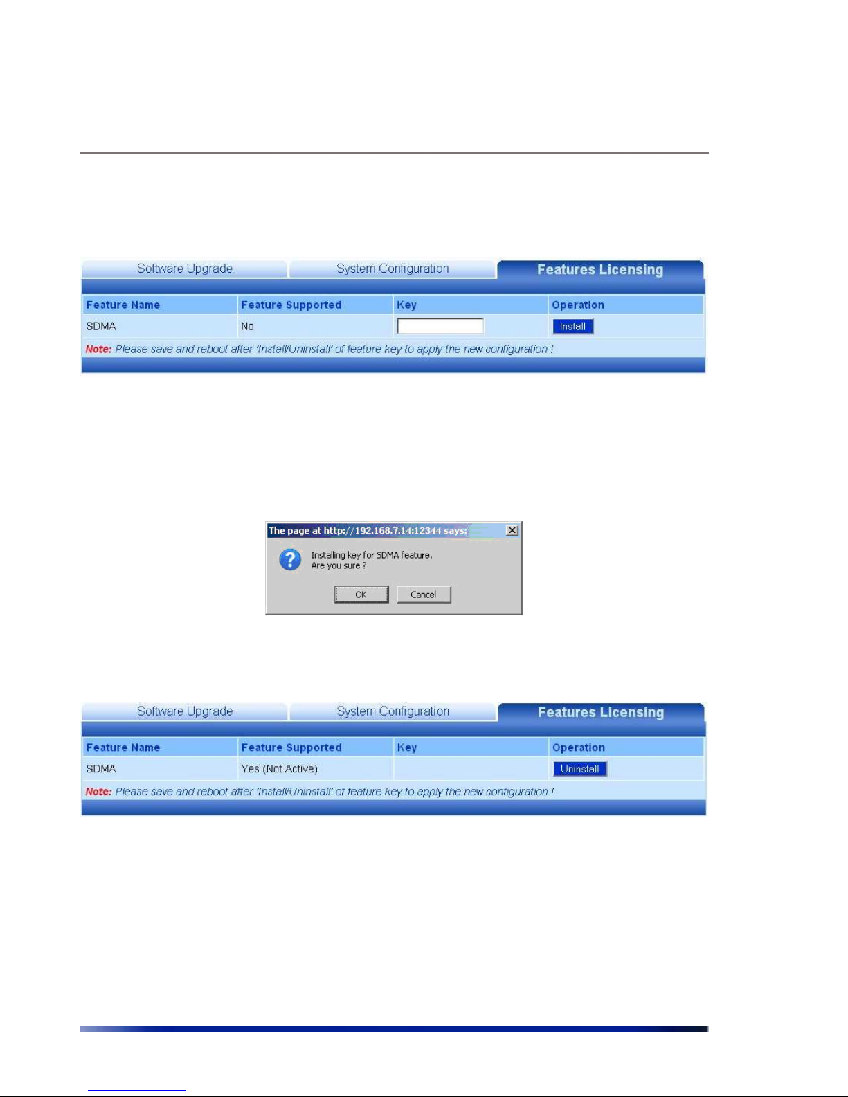
Click on the “Install” button. A pop-up window will appears.
Figure 2.6 Features Licensing Tab- SDMA Installation
After acceptance, the feature will be installed but not active
Figure 2.7 SDMA after Installation
For SDMA activation, the system configuration must be saved and the unit must be rebooted.
Managing the System Configuration
25 Wavion
Figure 2.8 SDMA Installed and Active
Note: Although the feature is installed, you can enable and disable it
through the Wireless tab in Network-> Wireless menu.
Managing the System Configuration
Rev 4.0 User Manual 26
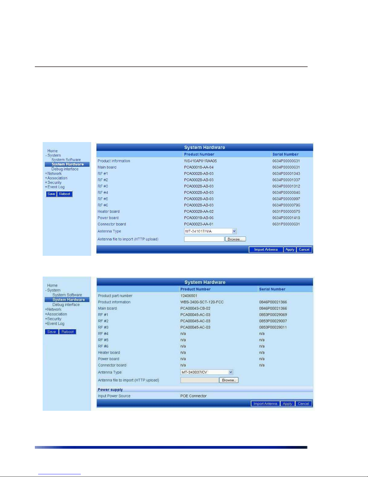
Viewing the System Hardware Components
The System Hardware page lists the components of the system.
Figure 2.9 System Hardware Page-WBS-2400
Figure 2.10 System Hardware Page-WBS-2400-SCT
The following information is displayed on the System Hardware page for each component.

Managing the System Configuration
27 Wavion
Table- 2.3 System Hardware page
Field Description
Product
Number
An internal ID which identifies the components of the system.
There are no field replaceable units. This information may be
used to identify the hardware components.
Serial
Number
An internal ID which identifies the date of manufacture,
production lot, and individual component. There are no field
replaceable units. This information along with the product
number may be used to identify the specific hardware
component.
Antenna Type
The Antenna Type indicates the default antenna type that is
installed in the unit.
Although WBS-2400 antennas can be detached from the unit,
they should be considered as integral part of the WBS-2400. The
beamforming capability takes into account the specific attributes
of the antennas. Replacement of antenna should never be done
without official instructions from Wavion Technical Support
person
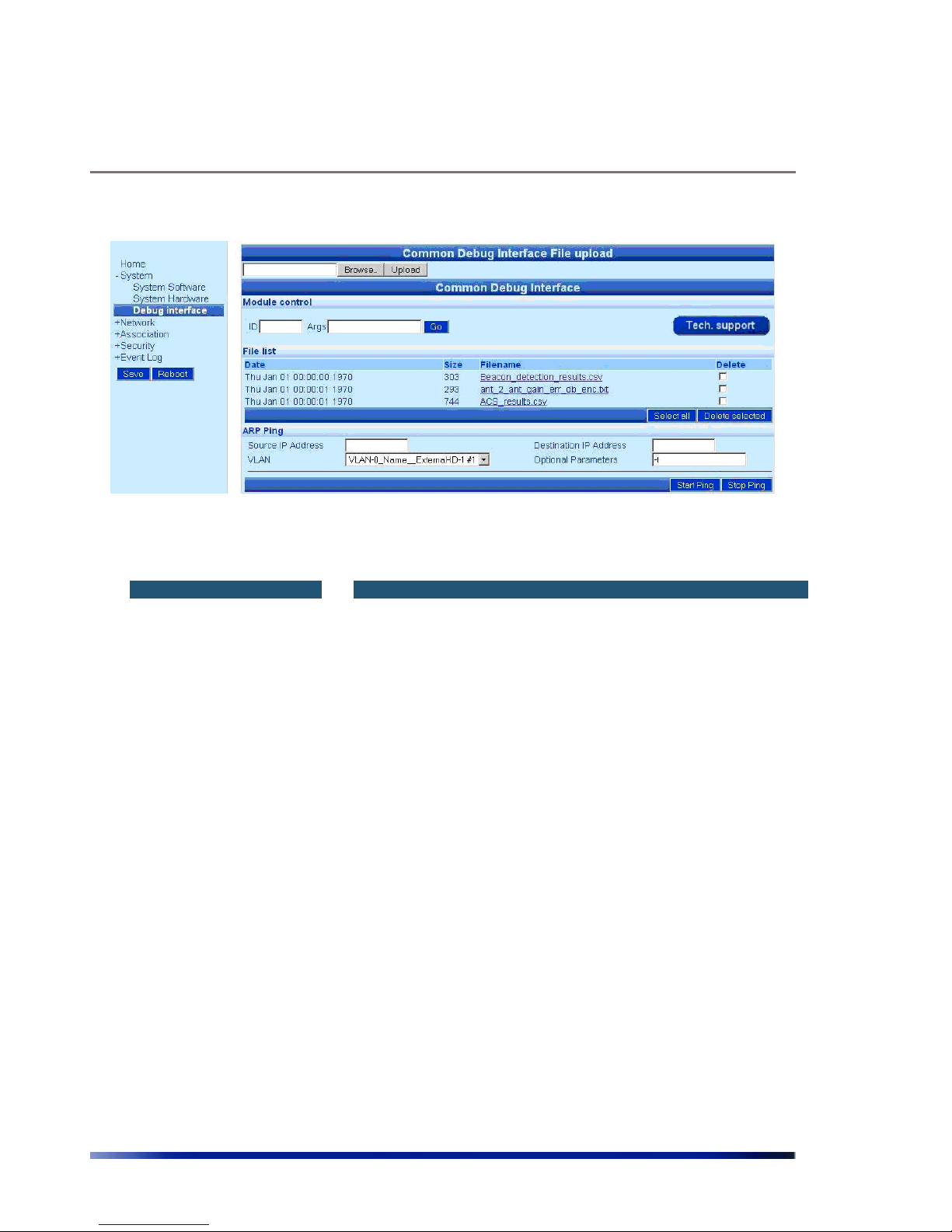
Debug Interface
The Debug interface page allows Wavion's technical support team to get critical information
about the status of your system Software and Hardware.
In case of faulty system behavior you may be asked by a Wavion technical support member to
save the file listed in the Debug Interface page, or to enter a code that will generate special file
for engineer's inspection.
Managing the System Configuration
Rev 4.0 User Manual 28
Figure 2.11 Debug Interface Page
Table- 2.4 Debug Interface page
Field Description
Common Debug
Interface File Upload
In rare cases you will be asked by Wavion technical person to upload
a file into the system to help critical issue debugging.
Module Control
ID/Args
These codes will be given by Wavion Technical support person to
load to the system in order to get help with critical debugging.
Tech. support
button
This button creates a Tech Support Report file with all the unit’s
configuration and other information needed by Wavion Tech Support
Department in order to debug a problem.
File List
This list contains debugging files that helps Wavion technical support
to define HW or SW problems in field.
Please send this file to Wavion technical support for analyzing your
system conditions.
ARP PING
This tool test the connectivity of the WBS by sending a L2 PING
towards a device in a specific broadcast domain
Source IP address
IP address to be set as SENDER in the ARP message. This IP should
be an available address and must lay on the same subnet as the
destination IP address
Destination IP address
IP address to be set as TARGET in the ARP message. This IP address
must lay on the same subnet as the source IP address

Managing the System Configuration
29 Wavion
VLAN
Select the VLAN (broadcast domain) where the IP addresses should
be valid
Optional Parameters
Leave it blank for a repetition of 5 PING. Select “–t” for a non-stop
PING stream.
Managing Network Interfaces
Chapter 3
Managing Network Interfaces
You can view the status of the network interfaces. There is a summary page and a separate
page where each interface can be managed.
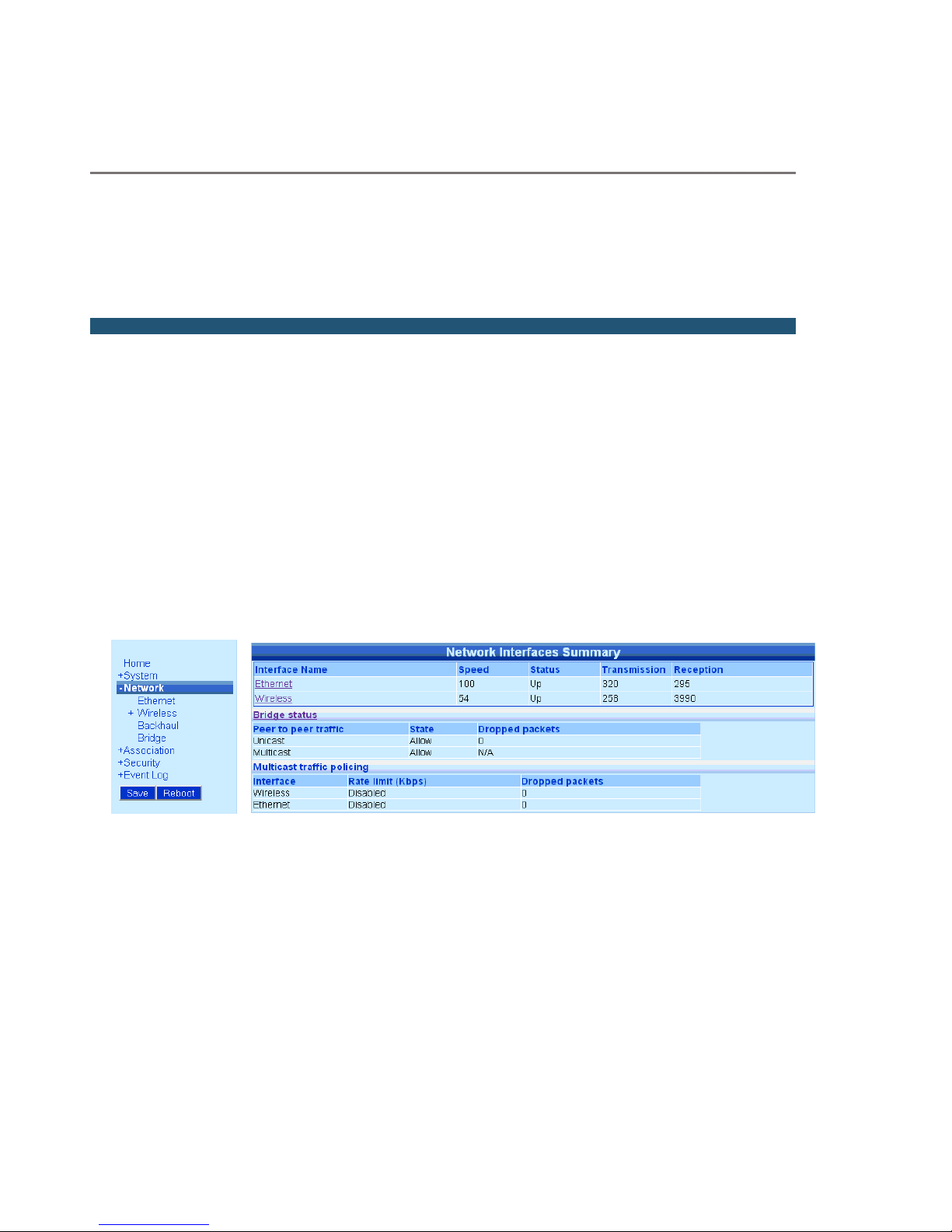
Viewing the Network Interfaces Summary
To view the Network Interfaces Summary page
• Click Network Interfaces in the menu.
Depending on whether the base station has an embedded Ethernet Switch or not the view of
the Network Interface Summary page will be different
Figure 3.1 Network Interfaces Summary for a system without embedded switch
You can click Ethernet or Wireless on either the page or the menu bar to view the Ethernet or
Wireless Interface pages.
 Loading...