

Wavion WBS-2400, WBS-5800, WBS-5000P Installation Manual
WBS-2400 & WBS-5800
& WBS-5000P
Outdoor Wi-Fi Base Station
Installation Guide
Rev. 7
March 2012

Note: To better reflect the value of Wavion products we are changing the name of our product
family from Access Points (AP) to Wireless Base Stations (WBS), consequently the existing WS-
410 product name will be changed to Wavion WBS-2400.
The new product name emphasizes the difference in architecture (Multiple Radio system) and
the value to customer, superiority in performance (coverage, capacity, indoor penetration and
immunity to interference) of Wavion WiFi base station over any other standard outdoor WiFi
access point products available in the market.
All references in Wavion's documentation to WS-410 refer also to the WBS-2400, and vice
versa. Both products are exactly the same except for the name change.
Copyright Notice
©2006, 2007, 2008 Wavion, Inc. All rights reserved. Wavion is a registered trademark of
Wavion in the United States and certain other jurisdictions. Specifications are subject to change
without notice.
FCC Notice to Users and Operators
This equipment has been tested and found to comply with the limits for a Class B digital device,
pursuant to Part 15 of the FCC Rules. These limits are designed to provide reasonable
protection against harmful interference when the equipment is operated in a commercial
environment. This equipment generates, uses, and can radiate radio frequency energy and, if
not installed and used in accordance with the instruction manual, may cause harmful
interference to radio communications. Operation of this equipment in a residential area is likely
to cause harmful interference, in which case the user will be required to correct the interference
at his own expense. If this equipment does cause interference to radio or television reception,
which can be determined by turning the equipment off and on, the user is encouraged to
correct the interference by using one of the following measures:
• Reorient or relocate the receiving antenna.
• Increase separation between the equipment and receiver.
• Connect the equipment to an outlet on a circuit different from that to which the receiver is
connected.
• Consult the dealer or an experienced radio/TV technician.
Changes or modifications to this unit not expressly approved by
the party responsible for compliance could void the user’s
authority to operate the equipment.

Installation Guide 3
Note This device complies with part 15 of the FCC Rules. Operation is subject to
the following two conditions: (1) This device may not cause harmful interference,
and (2) this device must accept any interference received, including interference
that may cause undesired operation.
R&TTE Compliance Statement
This equipment (ETSI-models only) complies with all the requirements of DIRECTIVE
1999/5/CE OF THE EUROPEAN PARLIAMENT AND THE COUNCIL of March 9, 1999 on
radio equipment and telecommunication terminal Equipment and the mutual recognition
of their conformity (R&TTE)

4 Wavion Networks
Contents
Chap t e r 1 About This Guide ........................................................................ 5
Preface .................................................................................................... 5
Conventions ............................................................................................. 5
Contacting Technical Support .................................................................... 6
Chap t e r 2 Introduction ............................................................................... 7
Chap t e r 3 Package Content ........................................................................ 8
Chap t e r 4 Installing the Wavion WBS-2400/5800/5000P Metro Base
Station 10
Important Safety Instructions .................................................................. 11
Preparing for Installation ......................................................................... 12
Choosing a Location ................................................................................ 13
Preparing the Site ................................................................................... 13
Mounting Strategies ................................................................................ 14
Using Hose Clamps ................................................................................. 15
Mounting on a Pole/Streetlight ................................................................ 16
Metal/Wood/Streetlight Pole Mounting ..................................................... 16
Grounding the Data Protection Device ...................................................... 20
Connecting Antennas .............................................................................. 22
Antenna Sealing ..................................................................................... 22
Connecting Power and DATA - Option 1 ................................................... 26
Connecting Power and DATA - Option 2 ................................................... 30
Safety Information for the Wavion WBS-2400/5800/5000P........................ 33
Service Instructions ................................................................................ 34
Chap t e r 5 Product Specification WBS-2400 ............................................. 35
Chap t e r 6 Antenna 2.4GHz Specifications and Patterns .......................... 39
SF-245W 2.4GHz Omnidirectional Antenna ............................................... 39
MT_342015NV_SN_035 2.4 GHz Antenna ................................................. 39
MT_341017NA_SN_101_EL 2.4 GHz Antenna ........................................... 43
SF-245W-10SR 2.4 GHz Antenna .............................................................. 46
2.4GHz AP antenna, 10 deg down-tilt ............................................... 46
Chap t e r 7 Product Specification WBS-5800 ............................................. 47
Chap t e r 8 Antenna 5.8GHz Specifications and Patterns .......................... 51
MT-462007-N 5.8GHz Omnidirectional Antenna ........................................ 51
Gain versus Elevation .............................................................................. 52
Chap t e r 9 Installation Accessories ........................................................... 54
Ethernet Cables ...................................................................................... 54
Sun Protection ........................................................................................ 54
Lightning Protection ................................................................................ 54
Power Over Ethernet ............................................................................... 55
Chap t e r 1 0 Wind Loading Considerations .................................................. 56
Chap t e r 1 1 Acronyms .................................................................................. 57
Chap t e r 1 2 Appendix A: WBS-2400/5800/5000P Product list .................. 59
5 Wavion Networks
Chapter 1
About This Guide
Preface
This guide details the Wavion WBS-2400/5800/5000P installation procedures. The
intended audience of this document is trained technical professionals.
Conventions
The exclamation point within a triangle is intended to alert the user to the
presence of important operating and maintenance (servicing) instructions in
the literature accompanying the product.
The lightning flash with an arrowhead symbol within a triangle is intended to
alert the user to the presence of un-insulated dangerous voltage within the
product’s enclosure that may be of sufficient magnitude to constitute a risk of
electric shock to persons.
The notebook is intended to alert the user of a note containing further
information.
Antenna photos are used for illustration purposes.

About This Guide
6 Wavion Networks
Contacting Technical Support
For technical support, contact Wavion using these methods:
Address:
Wavion Technical Support
Wavion
6 Hayetzira Street,
PO BOX 580
Yoqneam Illit, 20692
Israel
Telephone:
+972-4-9097380
Fax:
+972-4-9097322
Email:
support@wavionnetworks.com
Web:
www.wavionnetworks.com

Introduction
Installation Guide 7
Chapter 2
Introduction
WBS-2400/5800/5000P a high capacity, IP services oriented Broadband Wireless access system.
WBS-2400/5800/5000P is a new category of Broadband Wireless Base Station designed from
the ground up for metro-Wi-Fi deployments. The system employs wireless packet switched data
technology to support high-speed IP services including fast Internet and Virtual Private
Networks. WBS-2400/5800/5000P users are provided with a network connection that is always
on, supporting immediate access to the Internet and other IP services at high data rates. The
system is designed for cellular-like deployment, enabling the system architecture to vary in size
and structure. A system can include any number of cells, each containing several base station
access units for better coverage of densely populated areas.
It is based on six antennas and radios and custom-built ASICs, utilizes Wavion's powerful multiantenna signal processing technologies, and provides significant performance gains to off-theshelf 802.11 standards-based
The WBS-2400/5800/5000P may be mounted on streetlights or rooftops and may be
easily interfaced with wired internet connections, wireless mesh or backhaul equipment.
Complete management of the WBS-2400/5800/5000P is provided through SNMP, a
graphical user interface, and SYSLOG services.

8 Wavion Networks
Chapter 3
Package Content
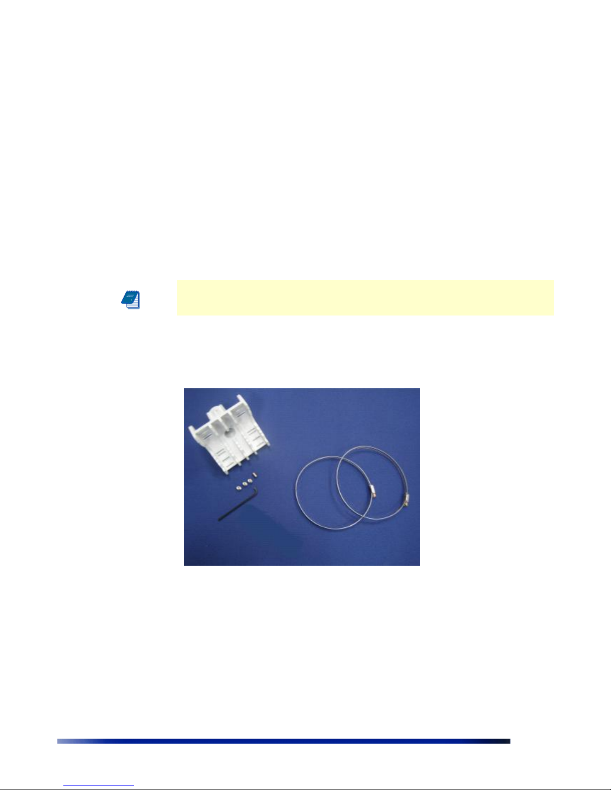
Check that the package contains:
POE injector unit with wall mounting kit
Outdoor Unit with a connection to an external antennas
6 antennas
Pole mounting bracket for the outdoor unit
Allen head wrench with 4 screws
Waterproof sealing tape for IP67 (band to sealing rubber) – Option 1
Plastic cap and cap cover – Option 2
Additional Equipment and Tools required for Installation
Ethernet cable (straight for connecting to a hub/switch)
Crimping tool for RJ-45 connectors.
Ground cable with an appropriate termination.
Mains plug adapter or termination plug (if the power plug on the supplied AC
power cord does not fit local power outlets).
Portable PC with Ethernet card and Telnet software and a straight Ethernet
cable.
WARNING: Use straight Ethernet (POE) cable connecting the injector to AF unit in order to have all
the features work properly (reset button and Link LED). Using cross cable might cause turn Link led
to “ON” permanently and also may be the cause software reset. DATA cable connecting the injector to
the network can be cross cable as well.

Package Content
Installation Guide 9
Addition tools and materials, including appropriate means (e.g. a pole) for
installing the outdoor equipment.
1/4-inch flat blade screwdriver
WARNING: ONLY experienced installation professionals who are familiar with
local building and safety codes and, wherever applicable, are licensed by the
appropriate government regulatory authorities should install outdoor units and
antennas. Failure to do so may void the WBS-2400/5800/5000P product
warranty and may expose the end user or Service Provider to legal and
financial liabilities. Wavion and its resellers or distributors are not liable for
injury, damage or regulation violations associated with the installation of
Outdoor Units or antennas

10 Wavion Networks
Chapter 4
Installing the Wavion WBS OMNI Metro Base
Station
This guide explains how to safely install the Wavion WBS-2400/WBS-5800/WBS-5000P
Metro Base Station. The following topics are covered in this chapter:
Important Safety Instructions
Preparing for Installation
Mounting Strategies
Using Hose Clamps
Mounting on a Pole, or Streetlight
Grounding the Wavion WBS
Connecting Antennas
Connecting Power and Data
Safety Information for the Wavion WBS
Service Instructions
Installation Guide 11
Important Safety Instructions
WARNING: It is illegal to modify the construction of this product. Modifying
the operating frequency or enhancing the transmit output power through the
use of external amplifiers or other equipment is specifically disallowed by the
"Telecommunications Act."
WARNING: This device is for outdoor or indoor use with conditions that no
harmful interference to authorized radio stations results from the operation
of this device. This device shall not influence aircraft security and/or
interfere with legal communications as defined in the "Telecommunications
Act." If this device is found to cause interference, the operator of this
equipment shall cease operating this device immediately until no
interference is achieved.
Note: This device must be installed by a trained professional, value added
reseller or systems integrator who is familiar with RF planning issues and the
regulatory limits in the United States of America.
Caution: Read and save these instructions. Heed all warnings. Follow all instructions.
Do not defeat the safety purpose of the grounding.
Caution: Only use attachments/accessories specified by the manufacturer.
Caution: Refer all servicing to qualified service personnel. Servicing is
required when the apparatus has been damaged in any way. For example, if
the power-supply cord or plug is damaged, liquid has been spilled on the
apparatus, objects have fallen into the apparatus, the apparatus has been
exposed to rain or moisture, it does not operate normally, or has been
dropped.
Warning: Risk of personal injury or death when installing this device! There
is a risk of personal injury or death if the WBS-2400/5800/5000Pantennas
come near electric power lines. Carefully read and follow all instructions in
this manual. By nature of the installation, you may be exposed to hazardous
environments and high voltage. Use caution when installing the outdoor
system.
Warning: This apparatus must be connected to earth ground
Warning: Do not open the unit. There is a risk of electric shock inside.
Caution: You are cautioned that any change or modification not expressly
approved
in this manual could void your authority to operate this equipment.
12 Wavion Networks
Caution: There are no user-serviceable parts inside. All service must be
performed by qualified personnel.
Caution Only UL listed parts and components will be used for installation. Use UL listed devices
having an environmental rating equal to or better than the enclosure rating to close all unfilled
openings.
Caution To maintain Overvoltage (Installation) Category II, install a suitable surge suppressor
device in the branch circuit to limit expected transients to Overvoltage Category II values. The
limits are based on IEC60664 and are also located in Table 2H of UL60950 (for mains 110V, the
transient rating is 1500V).
Caution The WBS-2400/5800/5000P/5000P must be installed only with the
equipped antennas.
Caution A minimum distance of 40cm from the WBS-2400/5800/5000P/5000P antenna should
be kept when the system is operated.
Caution Read and save these instructions. Heed all warnings. Follow all
instructions
Preparing for Installation
ONLY experienced installation professionals who are familiar with local building and
safety codes and, wherever applicable, are licensed by the appropriate government
regulatory authorities should install outdoor units and antennas.
The following lists the equipment required for installation and explains how to prepare
the installation site.
WARNING: Do not modify the construction of this product. Modifying
the operating frequency or enhancing the transmit output power
through the use of external amplifiers or other equipment is illegal.
WARNING This device is for use outdoors or indoors on the condition
that operation of this device causes no harmful interference to
authorized radio stations. This device shall not influence aircraft security
and/or interfere with legal communications. If this device is found to
cause interference, the operator of this equipment shall cease operating
this device immediately.

Installation Guide 13
Choosing a Location
To ensure the optimal performance select the locations for the equipment using the following
guidelines:
The antenna (not-integrated on the front panel of the outdoor unit) should
provide a direct, or near line of sight, with the sector location that need to be
covered.
The antenna should be aligned to face the CPEs that aim to be in service, higher
the placement of the antenna, the better the achievable link quality (but not in all
cases).
Average rooftop (depend on the topology of the location) should be
The location of the outdoor unit should enable easy access to the unit for
installation and testing
Avoid installations in locations that devices operating in the same
frequency range.
The outdoor unit should be installed at the highest point of a metal pole that
there will be no interference caused by RF reflections. If this is not possible, it
should be installed at least 3 meters from the metal pole.
It is recommended to use maximum distance possible from an RF radiating
source.
Preparing the Site
1. Follow the appropriate electrical and building codes to ensure safe and
durable wiring.
2. Follow the National Electrical Code (NEC) requirements, unless local codes in
your area take precedence over the NEC code
3. The length of the indoor-to-outdoor Ethernet cable should not exceed 90
meters. The length of the Ethernet cable connecting the indoor unit to the
user's equipment, together with the length of the Indoor-to-Outdoor cable,
should not exceed 100 meters.
4. An appropriate ground cable should be available. Connect a grounding cable
between the Ground terminal of the outdoor unit and a good ground
connection.
Please refer to standards for building entrance protection.
14 Wavion Networks
Mounting Strategies
Consider the available mounting structures and antenna clearance when choosing a
mounting location. Wavion outdoor unit WBS-2400/5800/5000P should always be
mounted with the top of the unit parallel to the ground, and with the antennas pointing
upward and clear of obstruction.
It is recommended to attach ground and data cables to the WBS-2400/5800/5000P prior
to mounting. Before mounting the WBS-2400/5800/5000P, read the wiring instructions in
Grounding the Wavion WBS-2400/5800/5000P and Connecting Power and Data.
Note: The WBS-2400/5800/5000P/5000P should be mounted with at least 4
ft/3 Meter of clearance around the antennas to eliminate potential interference
from the mounting structure.
Figure 4.1 Pole mounting kit for the Outdoor Unit & Sealing kit
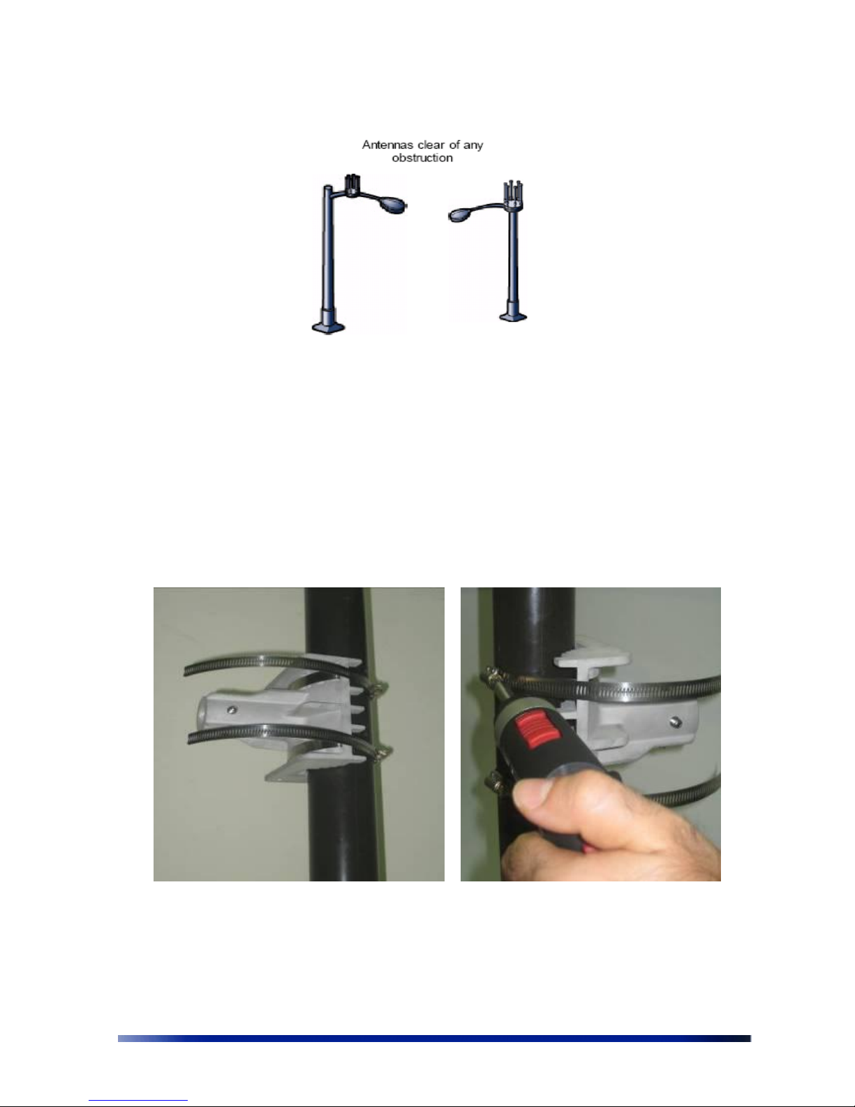
Figure 4.2 demonstrate acceptable options for mounting on a streetlight. In both cases
the WBS-2400/5800/5000P/5000P is mounted to ensure clearance for the antennas
above the height of the streetlight.
Installation Guide 15
Figure 4.2 Example Mounting Locations on a Streetlight
Using Hose Clamps
Special hose clamps that include threaded holes are used by the mounting assembly to
secure the WBS-2400/5800/5000P/5000P to the mounting structure. Figure 4.3
demonstrate how to correctly use the hose clamps. The bands must be threaded through
holes in the pole bracket, and then attached to either a vertical or a horizontal pole and
tightened.
There are two pairs of threaded holes on the back of the unit, enabling to use the special
clamps for mounting the unit on diverse pole diameters.
Figure 4.3 Using Special Hose Clamps & Screwing the Clamps
16 Wavion Networks
Mounting on a Pole/Streetlight
WBS-2400/5800/5000P/5000P can be mounted on a pole, tower, or streetlight. It is
recommended to mount the WBS-2400/5800/5000P/5000P on aluminum or
galvanized steel structures.
Note The Wavion WBS-2400/5800/5000P/5000P must be mounted with
the top of the unit parallel with the ground and with the antennas pointing
upward.
Note Before mounting the WBS-2400/5800/5000P/5000P, read the wiring
instructions in Grounding the Wavion WBS-2400/5800/5000P and Connecting a
Data Port chapter.
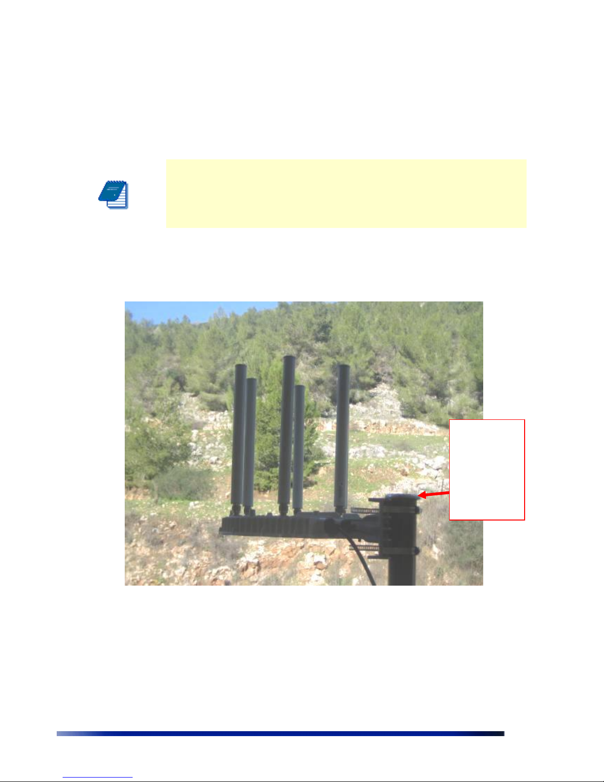
Metal/Wood/Streetlight Pole Mounting
Figure 4.4 illustrate how to mount an outdoor unit on a pole, using the clamp on an outdoor metal
vertical pole.
Figure 4.4 Mounting on a Vertical Pole
Metal pole
installation
requires that
the antennas
are higher
than the top
of the pole
Installation Guide 17
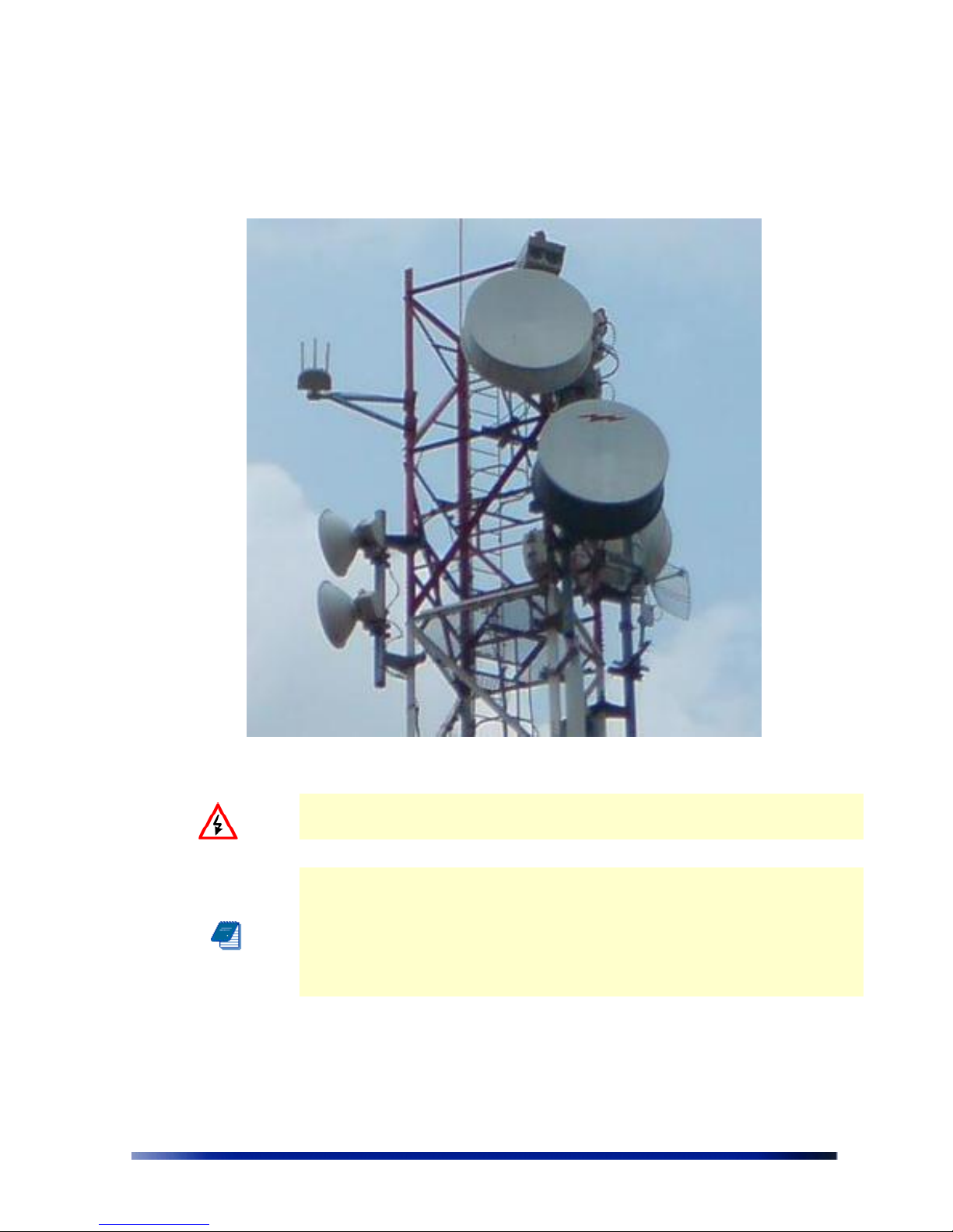
Figure 4.4 illustrate how to mount an outdoor unit on horizontal pole – at least 1 meter
inside the tower or wall
Figure 4.5 Mounting on a Horizontal Pole
Warning: Metal pole installation requires that the antennas are higher than
the top of the pole.
Note Be sure to mount the unit with the bottom panel, which includes the
LED indicators, facing downward
Note Antennas must be higher than the top of the metal pole and clear of
any obstructions
Note Mounting to wood, concrete, or painted poles requires primary
grounding for the unit. Check the national electrical codes in your area for
specific rules.
To mount the Wavion WBS-2400/5800/5000P on a metal/wood/streetlight
pole:
1. Choose a mounting location. You can attach the WBS-2400/5800/5000P outdoor unit
to any pole or pipe with diameter of 3-10 inches. Wooden poles of larger diameter
18 Wavion Networks
require different types of clamps (any streetlight arm with diameter of 3 to 10 inches
will fit for this installation).
2. Slip the bands of the hose clamps through the slots of the pole bracket
3. Use the hose clamps to fasten the pole bracket to the pole.
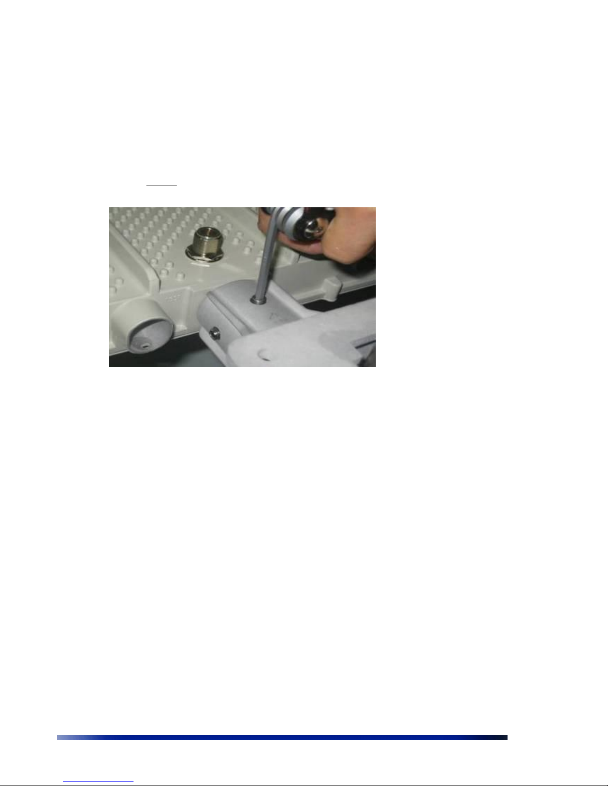
4. Insert the WBS-2400/5800/5000P onto the pole bracket, obtain the correct position
and tighten 4 bolts using 4mm Allen wrench.
Figure 4.6 Attaching the WBS-2400/5800/5000P to the pole bracket
 Loading...