

Page 1

SC5800 Digital Radio
User Manual
for
5.725 to 5.850-GHz Frequency Band
for Version 2
Document Number: 862-01881: Issue 7.1
Last Revised: September 17, 2001
Wave Wireless Networking
Division of SPEEDCOM Wireless
7020 Professional Parkway East
Sarasota, FL 34240
941-358-9283
941-355-0219 FAX
www.wavewireless.com
Page 2

Page 3

SPEEDCOM SC5800 User Manual
Issue Status
THIS MANUAL ADDRESS FEATURES SPECIFIC TO VERSION 2 OF THE
SPEEDCOM SC5800. PLEASE IGNORE REFERENCES TO OTHER
VERSIONS.
The following sections are new additions to Issue 7:
• Added new address on cover page
• Update on Reset Button functionality description (see page 15)
• Interconnection Cable Wiring Description: corrected third columns
for Pins 1 and 2 (see page 32) and added notes on bottom of page
• MIB definition additions (see pages 8 3 through 97)
• Product receive sensitivity level adjustment (see page 61)
• FCC notice additions and Indoor unit firmware upgrade notice added
(throughout manual)
• MIB elements deprecated such as ResetALLRFPerformanceData
and ResetAllG826 and other modified Groups notified by a “+” (see
pages 83 through 97).
FEDERAL COMMUNICATIONS COMMISSION NOTICE
The equipment has been tested and found to comply with the limits for Class A digital devices,
pursuant to Part 15 of the FCC Rules.
These limits are designed to provide reasonable protection against harmful interference when the
equipment is operated in a commercial environment. This equipment generates, uses, and can
radiate radio frequency energy and, if not installed and used in accordance with the instruction
manual, may cause harmful interference to radio communications.
Operation of this equipment in a residential area is likely to cause harmful interference in which
case the user will be required to correct the interference at his own expense.
The manufacturer is not responsible for any radio or TV interference caused by unauthorized
modifications to this equipment. Such modifications could void the user's authority to operate the
equipment.
This device complies with Part 15 of the FCC Rules. Operation is subject to the following two
conditions: (1) this device may not cause interference, and (2) this device must accept any
interference, including interference that may cause undesired operation of the device.
1
Page 4

SPEEDCOM SC5800 User Manual
WARNING- To comply with FCC RF exposure limits, the
antennas for this transmitter must be fix-mounted to
provide a separation distance of 2 meters (6.6 ft) or more
from all persons to satisfy RF exposure requirements.
This equipment must be professionally installed.
Publication Number: 862-01881
Issue 7.1
September 17, 2001
Wave Wireless Networking Copyright Statement
Wave Wireless Networking products are manufactured under a quality system certified to ISO
9001 specifications. All trademarks mentioned in this document are the property of their
respective owners. Wave Wireless Networking and SPEEDCOM Wireless Corporation do not
take responsibility for any damages incurred due to technical inaccuracies in this document.
Contents are subject to change without notification. © 2001 Wave Wireless Networking. All
rights reserved.
Technical Support
For more information, contact Wave Wireless Networking at:
Wave Wireless Networking
7020 Professional Parkway East
Sarasota, FL 34240
Technical Support:
941- 358-9283 phone
941 -3 5 5-0219 fax
www.wavewireless.com
2
Page 5

SPEEDCOM SC5800 User Manual
Table of Contents
Page
1
1.1 SC5800 Description 9
2
2.1 System Overview 11
2.2 Outdoor Unit 11
2.2.1 Frequency plans 12
2.2.2 RF Power Output Options 13
2.2.3 SC5800 Outdoor Unit 13
2.3 Indoor Unit 14
2.3.1 Payload Interface Options 14
2.3.2 Service (Wayside) Serial Data Channel 16
2.3.3 Element Manager Port 16
2.3.4 10BaseT Ethernet RJ45 Port 16
2.3.5 IU/OU Link LED 17
2.3.6 IU/OU Data Interconnect RJ45 17
INTRODUCTION 9
TECHNICAL DESCRIPTIO N 11
2.3.7 IU/OU Power Interconnect 17
2.3.8 Auxiliary In/Out Port 17
2.3.9 DC Power Input 17
2.3.10 Fuse Holder 17
2.3.11 ON/OFF Switch 18
2.3.12 Ground Terminal 18
3
3.1 System Type Selection 19
3.1.1 Antenna Selection (SC5800) 19
3.2 Site Evaluation 20
3.3 Multipath Effects 20
3.4 Interference Considerations 21
3.5 Micro-cell Backhaul Applications of SC5800 Digital Radios 22
3.5.1 Setting the Transmitted Power Levels 22
3.5.2 Frequency Multiplexing 22
PLANNING 19
3
Page 6

SPEEDCOM SC5800 User Manual
3.5.3 Antenna Isolation 22
4
4.1 Customer Furnished Tools and Equipment 24
4.2 Indoor Unit 25
4.2.1 Introduction 25
4.2.2 Installing the Indoor Unit in a Rack 25
4.2.3 Connecting a DC Power Supply 26
4.2.4 Balanced Payload Data 27
4.2.5 Connecting Auxiliary In/Out (Optional) 28
4.2.6 Connecting the Service (Wayside) Serial Channel (Optional) 29
4.2.7 Connecting the Element Manager Port 29
4.3 Outdoor Unit 30
4.3.1 SC5800 Outdoor Unit 30
4.4 Interconnection Cable Installation 31
4.4.1 INTERCONNECTION CABLE WIRING DESCRIPTION 32
5 ANTENNA ALIGNMENT AND SOFTWARE SETUP 33
INSTALLATION 23
5.1 Installation Equipment Required 33
5.2 Information Required 33
5.3 Antenna Alignment 33
5.3.1 Introduction 33
5.3.2 Alignment Procedure 34
5.3.3 Set Transmitted Power Level 34
5.4 Software Setup 35
5.5 Functional Test 35
5.5.1 Link Bit Error Rate Performance Test 35
5.6 SC5800 Installation Record 36
5.7 SC5800 Test Record 37
6
6.1 Introduction to the Network Management System 39
6.2 General Information 39
6.2.1 Microwave Digital Radio 40
6.3 Main Screen 41
NMS SOFTWARE 39
6.3.1 Link Elements Areas 42
6.4 NMS Menus 43
4
Page 7

SPEEDCOM SC5800 User Manual
6.4.1 Main Screen Menus 43
6.4.2 Main Screen Short-cut Buttons 45
6.5 Indoor Unit Configuration 45
6.5.1 Controls 45
6.5.2 Menu Items 48
6.6 Outdoor Unit Configuration 52
6.6.1 Controls 52
6.6.2 Menu Items 52
6.6.3 OU Station Info 53
6.6.4 Outdoor Unit Status 53
6.7 RF Link Error Status Monitoring 54
6.7.1 RF Link Status 54
6.7.2 Packet Error Rate Thresholds 54
6.7.3 RF Link Error Monitor 55
7
8
MAINTENANCE INFORMATION 57
TECHNICAL DATA 59
8.1 Environmental Requirements 59
8.1.1 Outdoor Equipment 59
8.1.2 Indoor Equipment 59
8.2 Mechanical Information for Outdoor Equipment 59
8.2.1 SC5800 Outdoor Unit 59
8.3 Mechanical Information for Indoor Equipment 59
8.4 Power Supply Requirements 5 9
8.5 Electrical Performance 60
8.5.1 General Characteristics 60
8.5.2 Transceiver Characteristics 60
8.5.3 RF Interface 61
8.5.4 Payload Data Interfaces 61
8.5.5 Auxiliary Input Interface (CONTACT CLOSURE) 62
8.5.6 Auxiliary Output Interface 62
8.5.7 Wayside channel interface 62
8.5.8 Element Manager Port Interface 62
8.5.9 Indoor/Outdoor Unit Interface 62
8.6 Ordering Information 64
5
Page 8

SPEEDCOM SC5800 User Manual
9
COMMUNICATIONS SETUP 67
APPENDIX A: ELEMENT MANAGER PORT POINT-TO-POINT SERIAL
9.1 Adding a Modem: Windows NT 68
9.2 Adding Dial-up Networking: Windows NT 72
9.2.1 To add dial -u p networking 72
9.3 Adding a Modem: Windows 95/98 77
9.4 Adding Dial-up Networking: Windows 95/98 79
10
10.1 SNMP and the SC5800 81
10.2 The MIB Elements – OID (Object ID) DESCRIPTIONS 83
10.3 The MIB elements – TRAP DESCRIPTIONS 97
11
‘REMOTE’-CONFIGURED INDOOR UNIT 101
11.1 IP CONFIGURATION OF THE SC5800 – ROUTING CONFIGURATION 10 1
11.2 IP CONFIGURATION OF THE SC5800 – BRIDGING AND ROUTING CONFIGURATION
103
12
SUMMARY 105
APPENDIX B: MANAGEMENT OF THE SC5800 81
APPENDIX C: SETUP OF A PC (WIN 95, 98, NT) TO ALLOW PINGING OF A
APPENDIX D: SC5800 HARDWARE VERSION 2.X DIFFERENCES, COMPATI BILITY
13
APPENDIX E: FIXED ANTENNAS 10 6
6
Page 9

SPEEDCOM SC5800 User Manual
7
Page 10

SPEEDCOM SC5800 User Manual
List of Abbreviations
BIT Built-in-Test
AIS Alarm Indication Signal
PE R Packet (or Block) Error Rate
DC Direct Current
DCE Data Communications Equipment
DRL Digital Radio Link
DRS Digital Radio Station
DTE Data Terminal Equipment
IU Indoor Unit
ISM Industrial, Scientific and Medical
LED Light Emitting Diode
LOS Loss of signal
Mbps Megabits per second
N.C Normally-closed
N.O Normally-open
NMS Network Management System
OU Outdoor Unit
PC Personal Computer
RF Radio Frequency
RSSI Received Signal Strength Indication
SNMP Simple Network Management Protocol
8
Page 11

SPEEDCOM SC5800 User Manual
1 INTRODUCTION
1.1 SC5800 Description
The SC5800 is a 5.8 GHz digital radio system that provides short to medium range,
point-to-point digital communication with high data security at rates of E1, 2E1 or
4E1. Alternatively, the radio can be software configured to convey T1, 2T1 or 4T1.
The radio can also be configured to bridge or route IP via a 10BaseT Ethernet port.
The data rates scale depending on the number of enabled E1/T1 tributaries and
whether the data is being bridged or routed. The product makes use of spread
spectrum technology and may be operated license-free in the 5.8 GHz ISM band. It
is ideal for applications such as:
• Telecommunications companies, cellular operators and private carriers.
• Cellular/PCS base station interconnects.
• Internet distribution.
• Video surveillance data distribution.
• Rural communications.
The SC5800 consists of two main parts:
• An Outdoor Unit operating in the 5.8 GHz ISM frequency band.
• An Indoor Unit, available with a Telecommunications (1, 2 or 4E1 or 1, 2 or
4T1) interface and a Data interface (10BaseT Ethernet).
Interconnection between the Outdoor Unit and Indoor Unit is achieved using a lowcost UV -protected STP (Screened Twisted Pair: 4 pairs) data cable and a UVprotected 2-core power cable. The SC5800 series product uses a split Indoor Unit
and Outdoor Unit configuration for lowest loss between the antenna and the
transceiver, thereby ensuring optimal long -range performance.
SC5800 Outdoor Unit uses a Type-N RF (female) output connector for connection to
any 5.8 GHz antenna for applications where long range is required.
9
Page 12

SPEEDCOM SC5800 User Manual
Table 1 lists the SC5800 model variants.
Table 1. SC5800 model variants
Model Number Interfaces Antenna Coupling Antenna Type
SC5801 E1/T1
10BaseT Ethernet
SC5802 2 x E1 / 2 x T1
10BaseT Ethernet
SC5804 4 x E1 / 4 x T1
10BaseT Ethernet
N-type Female Customer
supplied
N-type Female Customer
supplied
N-type Female Customer
supplied
For information about ordering supplies, see Section 8.6, Ordering Information, page
64.
The Network Management System provides control and management of the product.
SNMP support via an SNMP agent in the Indoor Unit e nsures open network
management compatibility.
Comprehensive data and RF loop -back functions ensure that the system is easy to
install and maintain.
10
Page 13
SPEEDCOM SC5800 User Manual
2 TECHNICAL DESCRIPTION
2.1 System Overview
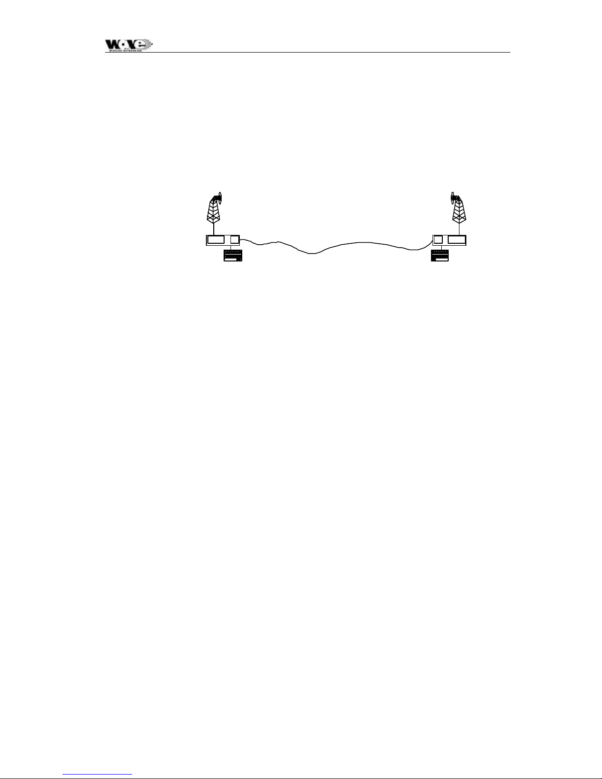
A SC5800 digital radio link (DRL) consists of a pair of SC5800 radio stations.
SC5800 ODU
SC5800 IDU
SC5800 ODU
SC5800 IDU
The SC5800 radio station consists of two main parts:
• An Outdoor Unit operating in the 5.8 GHz ISM frequency band. The Outdoor
Unit provides the radio transceiver functionality by accepting radio link data from
the Indoor Unit and converting it to the 5.8 GHz ISM frequency band using
spread spectrum modulation. The received signal is de-spread and transmitted
to the Indoor Unit in a digital format.
• An Indoor unit, available with 1, 2 or 4 E1 and 1, 2 or 4 T1 data interfaces
(choice of E1 or T1 is software selectable). The Indoor Unit combines nE1 or
nT1 data with Wayside Service Channel serial data and link IP data to be
transmitted across the radio link. The Indoor Unit also provides power to the
Outdoor Unit.
Interconnection between Outdoor Unit and Indoor Unit is achieved using low cost
data and power cables.
2.2 Outdoor Unit
The SC5800 Outdoor Unit makes use of Spread Spectrum modulation technology for
license-free operation in the 5.8 GHz ISM band.
User Data
User Data
For SC5800 operation, the 5.8 GHz ISM band is divided into upper and lower
frequency sub-bands. An SC5800 ‘High Band’ Outdoor Unit transmits in the higher
frequency sub-band and receives in the lower frequency sub-band, while a ‘Low
Band’ Outdoor Unit transmits in the lower sub-band and receives in the higher subband. An SC5800 radio link will use a ‘Low Band’ Outdoor Unit on one end of the
link to communicate with a ‘High Band’ Outdoor Unit on the other end.
The SC5800 Outdoor Unit uses a Type -N RF output connector for connection to any
5.8 GHz antenna for applications where long range is required.
11
Page 14
SPEEDCOM SC5800 User Manual
2.2.1 Frequency plans
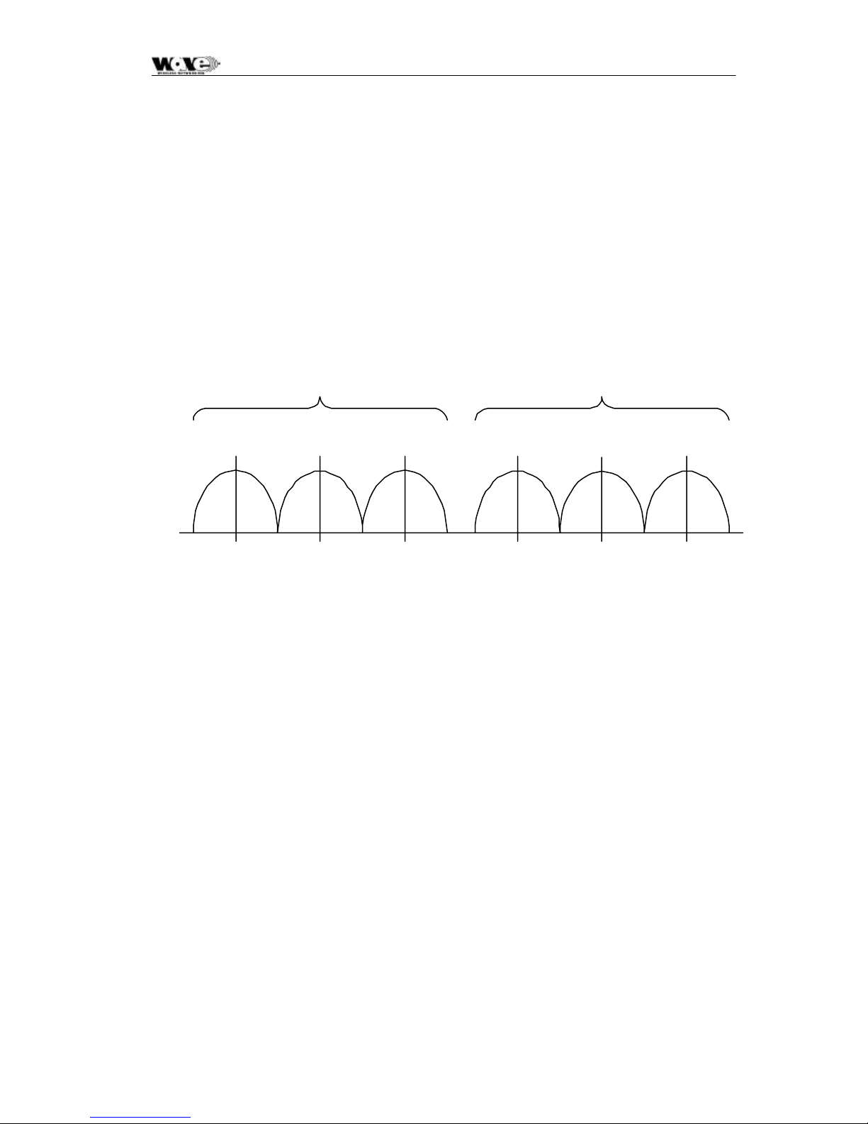
The SC5800 Outdoor Units operate in the 5.725 GHz to 5.850 GHz ISM frequency
band. The SC5800 has predefined frequency channel plans (termed A, B, C and D).
2.2.1.1 Frequency Channel Plan A, B and C
Transmit-to-receive channel spacing for frequency channel plans A, B and C is 69
MHz. The channel spacing is based on the bandwidth occupied by the spread
spectrum signal (approximately 17 MHz) and is used to optimize link performance.
In the case of plan A, plan B and C, note that both Outdoor Units of a link must be
set up to the same frequency channel plan (i.e., A, B or C).
LOW BAND TRANSMIT HIGH BAND TRANSMIT
A
L
B
L
C
L
C
H
B
H
A
H
5735 5753 5771 5804 5822 5840
Frequency (MHz)
Figure 1. Frequency channel plans A, B and C
12
Page 15

SPEEDCOM SC5800 User Manual
Frequency plan D allows independent control of transmit and receive frequencies.
This enables a very flexible frequency plan and can be used to overcome interference
in the 5.8 GHz ISM band.
The frequencies that can be used in the lower or upper sub-bands can be selected in
1 MHz increments. Performance degradation can be expected when operating
using channel plan D mode and the chosen frequencies are close to the sub-band
edges, such as a choice of one of the high frequencies in the lower sub -band and
one of the lower frequencies in the upper sub-band.
The allocation of Channel plan D frequencies is shown in Table 2.
Table 2. Channel plan D channel
frequencies
Sub-band Center Frequency (MHz )
L 5735-5771
H 5804-5840
2.2.2 RF Power Output Options
Frequency Channel Plan D
It is possible to adjust the output power on the OU using the supplied NMS software
or a SNMP Management application.
2.2.3 SC5800 Outdoor Unit
The SC5800 Outdoor Unit transmits and receives RF through a diplexer interfaced
via an RF cable to an external antenna. The unit has a type -N connector for
connection to the RF cable used between the OU and the antenna.
The SC5800 Outdoor Unit houses the following main parts:
• Transmit/Receive Modules
• Baseband Modulator/Demodulator Circuitry
• Microcontroller/Framing & Buffering Circuitry
• Power Amplifier
• Diplexer
13
Page 16
SPEEDCOM SC5800 User Manual
2.3 Indoor Unit
The Indoor Unit is designed for mounting in a 19” rack, occupying a 1U slot, or can
be tabletop standing.
The Indoor Unit accepts user nE1/nT1 and combines it with Wayside Service Serial
Data and IP data to be transmitted across the radio link.
The Indoor Unit is fitted with a DC power supply. An AC Bench Power supply can be
purchased separately.
2.3.1 Payload Interface Options
The Indoor Unit can be configured for nE1 or nT1 operation.
• 1, 2 or 4 x E1 (2.048 Mbps)
• 1, 2 or 4 x E1 (1.544 Mbps)
For E1 connectivity, bipolar AMI or HDB3 line coding is software selectable.
For T1 connectivity, bipolar AMI or B8ZS line coding is software selectable.
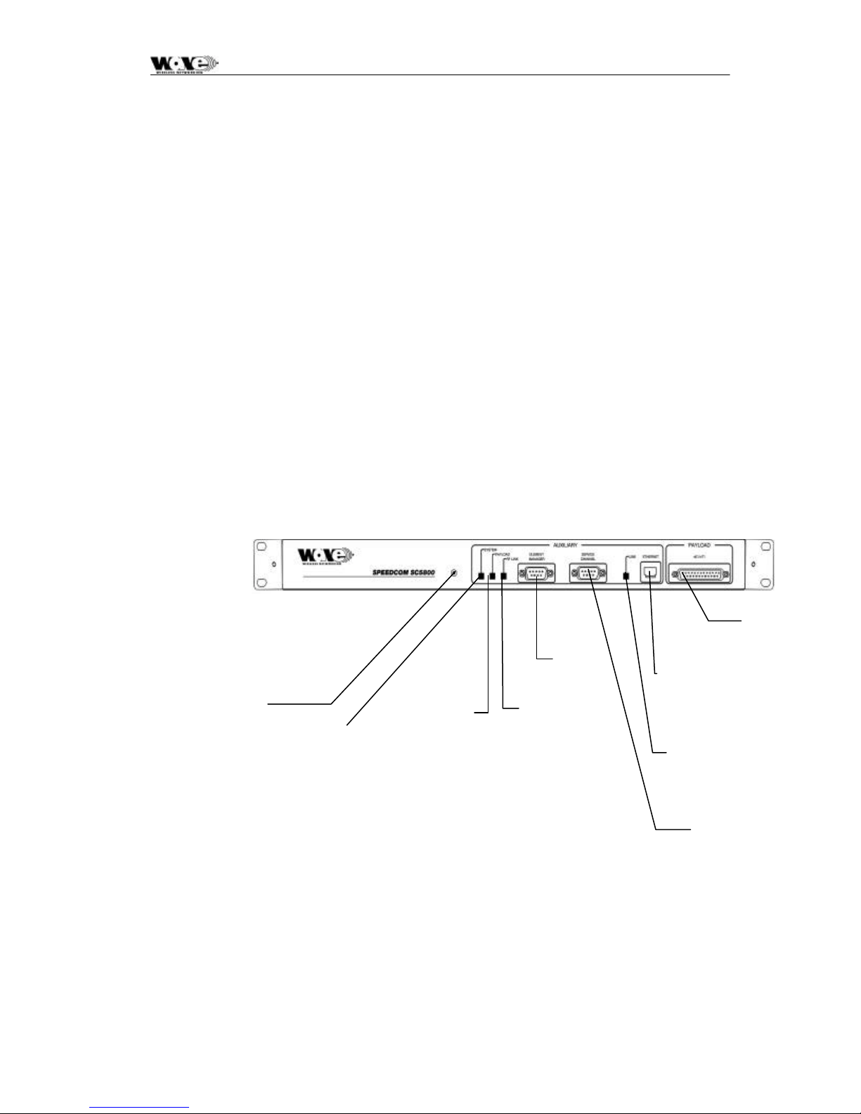
Reset/Configuration
Button
The Indoor Unit LED functionality is described as follows:
SYSTEM
nE1/nT1
Connector
Element
System
LED
Payload
LED
Manager
Connector
RF Link
LED
10BaseT RJ45
Socket
Ethernet Link LED
Figure 2. Indoor Unit Front Panel
Wayside Service
Serial Channel
Green OK, Orange (OU/IU Comms Error), Red (OU/IU Comms Down)
PAYLOAD
Green OK, Orange (AIS Detected), Red (LOS Detected)
RF LINK
Green OK, Orange (FEC Correcting Errors), Red (FEC unable to correct errors)
14
Page 17

SPEEDCOM SC5800 User Manual
Note: In ALL cases flashing red and orange LEDs imply historic alarm
conditions (The alarm can be cleared using the front panel button
‘position 1’: see next section).
Reset/Configuration Button
The Front Panel Button has the following functionality used to set up a radio (as
determined by different LEDs lighting up. ‘Position 1’ being RF Link LED (Green), 2
being Payload LED (Green), 3 being System LED (Green), 4 being RF Link LED
(Orange), 5 being Payload LED (Orange) and 6 being System LED (Orange) etc.
1. Clear Front Panel LEDs (and associated alarms in IU)
2. Clear Event Log in the Indoor Unit
3. Reset the Indoor Unit (don’t reset the non-volatile memory’s store of the IU’s
configuration parameters)
4. Routed Configuration: Reset the IU configuration parameters that are stored in
non-volatile memory (BATTERY-BACKED STATIC RAM) and configure as a ‘Far
Side IU’: (i.e., for a ROUTED IP configuration), set the Ethernet IP address as
10.11.1.2, Element Manager IP address to 10.12.1.2
5. Routed Configuration: Reset the IU configuration parameters that are stored in
non-volatile memory and configure as a ‘Near Side IU’: i.e. for a ROUTED IP
configuration set the Ethernet IP address as 10.2.1.2, Element Manager IP
address to 10.13.1.2
6. Routed Configuration: If you are not sure how the IU is configured (NEAR or
FAR side IU), reset it AS IS i.e. reset the ‘Near Side IU’ or ‘Far Side IU’
configuration parameters depending on how the IU is currently configured.
7. Bridged Configuration: Reset the IU configuration parameters that are stored in
non-volatile memory (BATTERY-BACKED STATIC RAM) and configure as a ‘Far
Side IU’. For a BRIDGED IP configuration, see Appendix C of this document for a
description of the default IP addresses.
8. Bridged Configuration: Reset the IU configuration parameters that are stored in
non-volatile memory and configure as a ‘Near Side IU’. For a BRIDGED IP
configuration, see Appendix C of thi s document for a description of the default IP
addresses.
9. 9, 10, 11 RESERVED
12. Set up Indoor Unit with E1 tributaries.
13. Set up Indoor Unit with T1 tributaries.
14. Deactivate buttons 4 onwards.
15. NB: All buttons can be REACTIVATED (i.e. undoing a 14 'reset') by doing a
power-on reset while holding the front-panel Reset Button in.
POSITIONS 4, 5, 6, 7 and 8 RESET THE INDOOR UNIT TO FACTORY DEFAULTS – THESE
RESETS ARE TYPICALLY ONLY USED ONCE
PARAMETERS IN NON -VOLATIL E MEMORY IN THE INDOOR UNITS). IF CHANGES ARE MADE
TO THE CONFIGURATION PARAMETERS AND THE USER DOES NOT WANT THESE TO
CHANGE WHEN A UNIT IS RESET, THE INDOOR UNIT CAN BE POWER -CYCLED OR POSITION
‘3’ MUST BE USED E.G. THIS TECHNIQUE IS USED IF THE IP ADDRESSES ASSOCIATED WITH
WARNING!
(THESE CHOICES RESET CERTAIN ADJUSTABLE
15
Page 18
SPEEDCOM SC5800 User Manual
THE NETWORK INTERFACES ARE ADJUSTED – THE PROCESSOR NEEDS TO BE RESET TO
ALLOW THE CHANGE/S TO BE IMPLEMENTED.
IF YOU OVER-RUN THE SELECTION YOU REQUIRE, CONTINUE UNTIL THE LEDs GO BLANK –
THEN, START AGAIN (OPTION AVAILABLE WITH RELEASE 2 OF IU FIRMWARE).
2.3.2 Service (Wayside) Serial Data Channel
This port supports asynchronous full duplex, serial data transfer at a speed of
115200 bps.
The interface type is RS-232 configured as DCE (Data Communications Equipment).
Handshaking can be None, Hardware.
2.3.3 Element Manager Port
This port is used for communication with the NMS software or with an SNMP
manager to control the SC5800 system. The port must be connected to a serial port
(configured for a speed of 115200 bps) on a personal computer t o use the NMS
software.
The interface type is RS-232 configured as DTE (Data Terminal Equipment).
Hardware handshaking is used.
2.3.4 10BaseT Ethernet RJ45 Port
This port is used for communication with the NMS software or with an SNMP
manager to control the SC5800 system.
The interface type is DTE (Data Terminal Equipment).
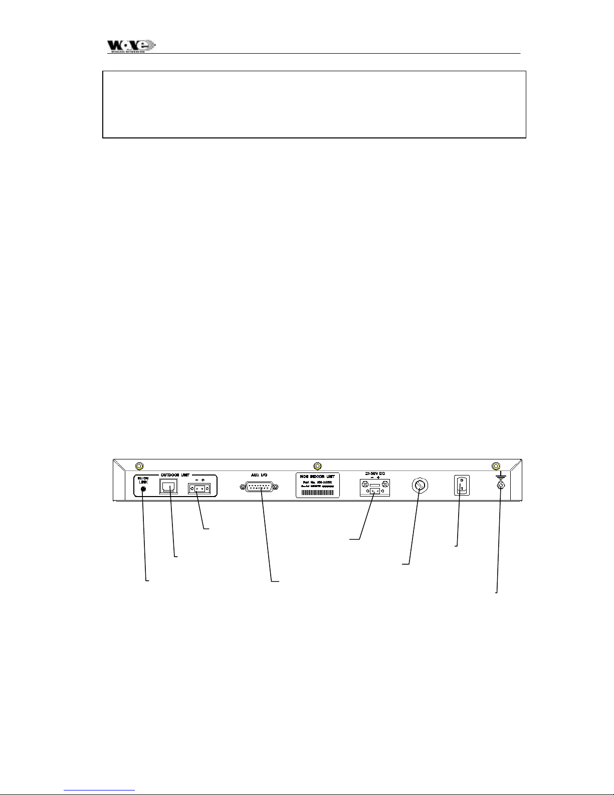
IU/OU Data
Interconnect RJ45
IU/OU Link LED
IU/OU Power
Interconnect
Figure 3. Indoor Unit Rear Panel
DC In
Auxiliary IO
Fuse
Holder
ON/OFF
Switch
Ground
Terminal
16
Page 19

SPEEDCOM SC5800 User Manual
2.3.5 IU/OU Link LED
This LED indicates if there is a suitable electrical connection between the Indoor and
Out door Units
1
.
2.3.6 IU/OU Data Interconnect RJ45
This receptacle accepts an RJ45 plug that connects to UV -protected STP (Screened
twisted pair) cable used between the IU and the OU.
2.3.7 IU/OU Power Interconnect
This connector (socket) is used for power interconne ction between the IU and the
OU. The connection is made using UV -protected 2-core cable. The cable is
connected to a GREEN connector, (i.e., a plug). The polarity sense (labeled) must
be maintained between the IU and the OU.
2.3.8 Auxiliary In/Out Port
The auxiliary in/out port is used for remote monitoring and control. The following are
provided:
• Two inputs (for sensing contact closure or opening) are provided to sense site
alarm inputs. The states of these alarm inputs can be monitored with NMS,
as well as from an SNMP Management Station.
• Two relay contact outputs, normally-open and normally -closed contacts, are
provided as alarm / auxiliary outputs. Output states are software customized
and controlled. The outputs are used to indicate alarm or other stat es
selected by the operator via the NMS or a SNMP Management Station.
2.3.9 DC Power Input
This connector (socket) is used for power input to the IU. The connection is made
using 2-core cable. The cable is connected to a gray connector, a plug. The
polarity -sense (labeled) must be observed and implemented.
2.3.10 Fuse Holder
This holder is used to hold a fuse (5A).
1
Note that only the Ethernet Physical interface is checked on V1 hardware with this LED, not the
RS232/485 interface. The integrity of the RS232/485 interface is checked using the front panel
“System LED”.
17
Page 20

SPEEDCOM SC5800 User Manual
2.3.11 ON/OFF Switch
This switch is used to control power input to the Indoor Unit (and indirectly the
Outdoor Unit).
2.3.12 Ground Terminal
This is used to accept connection to an earth strap, terminated with a crimped earth
lug. For details on wire/earth lug requirements, see Section 4.1, Custom Furnished
Tools & Equipment, page 24.
18
Page 21

SPEEDCOM SC5800 User Manual
3 PLANNING
This chapter is aimed at management and planning staff to enable them to assess
the requirements for installing an SC5800 digital radio link.
3. 1 System Type Selection
! The SC5800 system uses an Outdoor Unit with a type-N RF output for
connection to a range of antennas.
! Antenna polarization can used to co-locate multiple SC5800 systems.
! Antenna polarization can be used to overcome interference.
3.1.1 Antenna Selection (SC5800)
The antenna type must be selected before the SC5800 system is to be insta lled.
The chosen antenna must enable the system to operate with sufficient link fade
margin without excessive cost and allow the user’s ‘link availability requirements’ to
be met.
The main consideration when selecting an antenna is antenna gain measured in dBi.
A path loss analysis is highly recommended to determine the antenna gain needed
for adequate fade margin. The table below shows antenna selection guidelines for
some configurations. The distances are calculated for a 20 dB link fade margin.
Table 3 SC25800 Antenna Selection
Antenna Type Gain
(dBi)
0.15 m Flat panel 18 9 24
0.3 m Flat panel 24 30 24
0.6 m Flat panel 28 80 24
Distance (Km) Power level
(dBm)
19
Page 22
SPEEDCOM SC5800 User Manual
3.2 Site Evaluation
When planning a site for a digital radio link, it is of the utmost importance that you
take the operational environment of the proposed site into account.
The combined effect of atmospheric environmental factors such as rain and lightning,
atmospheric attenuation, signal path obstruction, propagation fading, air temperature
gradients, ice build-up, wind and solar radiation can contribute towards reducing the
level of performance of the system. In the higher frequency bands, rainfall is the
main attenuation mechanism that limits error performan ce. Ice and snow will have a
similar effect. Severely cold and excessively warm climatic conditions outside the
scope of the operating temperature range can affect the function of the system,
especially the outdoor equipment (see Section 8.1, Environmental Characteristics,
page 59 of this manual).
Also, if masts are not sufficiently rigid, very strong winds can affect the antenna
beam alignment and outdoor equipment reliability due to wind force build-up and/or
vibration of the mast-mounted equipment.
3.3 Multipath Effects
The SC5800 digital radio operates at frequencies close to 5.8 GHz and can be
influenced by the effects of multipath propagation. Understanding these effects will
help when installing an SC5800 digital radio li nk and maximize the reliability of the
link.
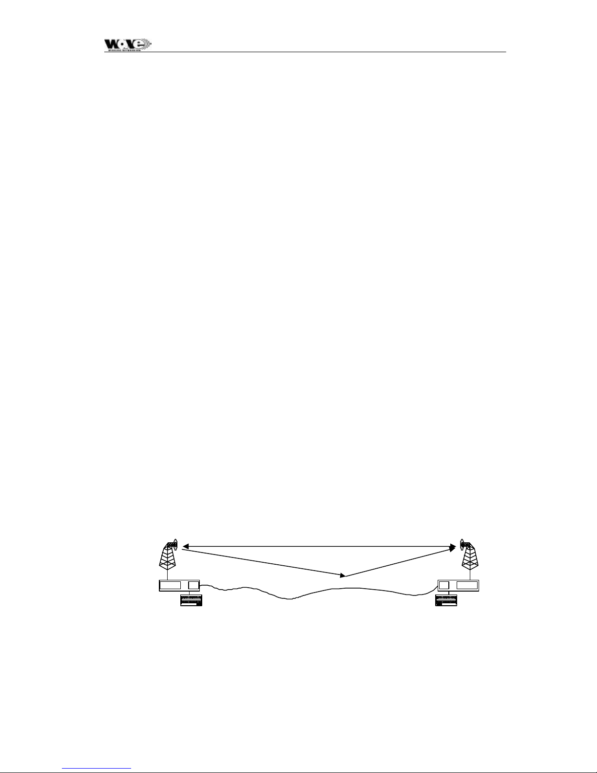
Multipath fading occurs when the receiving antenna receives not only the direct
signal from the transmitting antenna but also a signal from the transmitting antenna
that has reflected off the ground or nearby obstacles. The reflected signal takes a
longer path to reach the receiver and acts as interference since it is not in-phase
with the direct path signal. The amplitude of the interference can be almost equal to
that of the direct path signal, thus degrading the performance of the link .
Multipath propagation is dependent on transmit frequency and the specific geometry
of the link such as antenna heights, distance between the antennas and the local
terrain. To counteract multipath propagation, the installer can change the frequency
at which the link operates or adjust the height of one or both of the antennas.
Direct RF Path
SC5800 OU
SC5800
User Data
Reflection Path
SC5800 OU
SC5800 IU
User Data
Figure 4. Multipath Effects.
20
Page 23

SPEEDCOM SC5800 User Manual
3.4 Interference Considerations
The ISM frequency bands are used by devices that can cause interference to the
SC5800 radio system. Interference can be avoided by careful planning of the
system installation. The available methods for providing isolation from interfering
radiators are the following:
• Frequency diversity
• Antenna polarization
It is recommended to scan the proposed installation areas (using a spectrum
analyzer) to establish the presence of interference. The frequency spectrum should
be scanned over a sufficient time period to ensure that periodic transmissions are
recorded.
Interferers will cause problems if their amplitudes are not more than 20 dB below the
intended receive power level. A link path loss calculation should be performed to
determine the expected receive power level.
The procedure for selecting the optimum antenna polarization and system frequency
plan is the following:
• Perform a spectral analysis at each site in the link direction using a high gain
antenna.
• Repeat the spectral analysis for vertical and horizontal polarization.
• Select the polarization with the lowest interfering levels as the system
antenna polarization.
• Consult the SC5800 frequency channel plan as shown in Section 2.2.1,
Frequency Plans, page 12. Then, select the frequency plan that would operate
in an interference-free band. Give preference to channel plans A, B and C as
these are optimized for best receiver sensitivity.
• Install the ‘High Band’ and ‘Low Band’ Outdoor Units at the sites where they
would experience the lowest interference in their respective receive bands.
21
Page 24

SPEEDCOM SC5800 User Manual
3.5 Micro- cell Backhaul Applications of SC5800 Digital
Radios
In applications where more than one independent and separate links, need to radiate from a
central site, a number of parameters can be taken advantage of, to provide isolation and minimize
interference between these links:
• Frequency multiplexing
• Antenna polarization
• Choice of High Antenna Gain
It is important to note that these methods only provide isolation between two radio systems, and
that power levels in the separate systems should be balanced to ensure correct operation.
3.5.1 Setting the Transmitted Power Levels
To minimize interference, received power levels should be balanced between separate radio links.
This means that transmit power levels should be set to provide similar levels of received power, as
indicated by the RSSI values of the adjacent receivers at the central site.
3.5.2 Frequency Multiplexing
The SC5800 offers four frequency channel plans. A radio link requires two channels (one for
transmit and one to receive) to provide full-duplex operation. Each radio has a high and a low subband, one that it uses for transmission and another for reception. Terminology definition: the
‘High-band Outdoor Unit’ of a system transmits on the higher of the two sub-bands. The ‘Lowband Outdoor Unit’ of a system transmits on the lower of the two sub-bands. A system (link)
always has one High Band and one Low Band Outdoor Unit. It is important to note that unwanted
transmitted signals in adjacent frequency bands can affect other receivers operating in an
adjacent band if insufficient antenna isolation is provided. A solution is to group high-band or lowband Outdoor Units at the central site, rather than group high and low-band Outdoor Units
together.
3.5.3 Antenna Isolation
Separate links at a central site will have sufficient isol ation when radio systems operate outside
the radiation beamwidth or side lobes of the system antenna. The achievable isolation can be
established by examining the measured radiation patterns of the system antennas. Directional
isolation can be used if the antenna radiation is 15 dB or lower relative to the adjacent main
beam. Antennas with high directionality will allow reduced angular separation of adjacent
systems. Antenna cross-polarization isolation can be used for adjacent radio links, radiating in
the same direction. Typical isolation of 30 dB can be achieved using high quality antennas.
22
Page 25

SPEEDCOM SC5800 User Manual
4 INSTALLATION
This section describes a recommended installation procedure for the SC5800.
Recommended installation procedure:
1. Install the Indoor Unit.
2. Prepare and connect the cables to the Indoor Unit.
3. Install the Outdoor Unit and antenna.
4. Install the Indoor-to-Outdoor Unit interconnection cables (the power and data
cables).
5. Turn the Indoor Unit power on.
6. Perform the initial software setup using the supplied NMS application
7. Repeat items 1-5 for the remote site.
8. Align the antennas (use the RSSI voltage on the OU or the RSSI value from
the MIB or the NMS Graphic User Interface to assist with the setup).
9. Perform a functional test and commission the link.
10. Connect to user data.
11. Start the system.
Installation of the SC5800 elements is described in the following sections:
• Installing the Indoor Unit.
• Installing the Outdoor Unit and Antenna.
• Installing the interconnection cables.
23
Page 26

SPEEDCOM SC5800 User Manual
4.1 Customer Furnished Tools and Equipment
The following table lists tools and equipment required to install the SC5800 system.
General, IU-to-OU Interconnect
• Cable cutting and stripping tools.
• Earth lug crimp tools.
• 3 mm flat screwdriver - IU to OU power cable.
• RJ45 crimp tool - IU to OU data cable.
• Earth cable or strap rated at 45A with 5 mm earth lug earthing the Indoor and
Outdoor Units.
• Cable ties, used to secure the cables to the mast at regular intervals.
IU
• Pozi #2 screwdriver - IU mounting in a 19" rack and the earth lug.
• 2.5mm Alle n key - To change the position of the IU mounting brackets.
• DC power supply cable: minimum 2.5 mm square conductor, rated for 10 A. For
connection between the power supply and the Indoor Unit DC connector on the
rear panel.
• IU earth lug: 10-4 (10 square mm for wire and hole big enough for M4 thread)
OU
• 13 mm spanner (or Wrench) – used for attachment of OU to mounting bracket.
• 13 mm spanner - used for attachment of OU mounting bracket to pole.
• 2.5 mm Allen key - used to tighten OU connection box cover fasteners.
• OU earth lug: 10 -8 (10 square mm for wire and hole big enough for M8 thread)
For details on the data and RF cables, which are also customer furnished
equipment, see Section 7, Maintenance Information , page 57.
24
Page 27
SPEEDCOM SC5800 User Manual
4.2 Indoor Unit
4.2.1 Introduction
This section describes the recommended installation procedure for the Indoor Unit.
The Indoor Unit is designed for mounting in the DIN 41494 (19") racking standard and
occupies a 1U high slot. Desktop mounting is also possible.
The Indoor Unit’s payload (nE1, nT1 and 10BaseT Ethernet) and Service Channel
(‘Wayside serial’) data interfaces and Element Management interface are located on
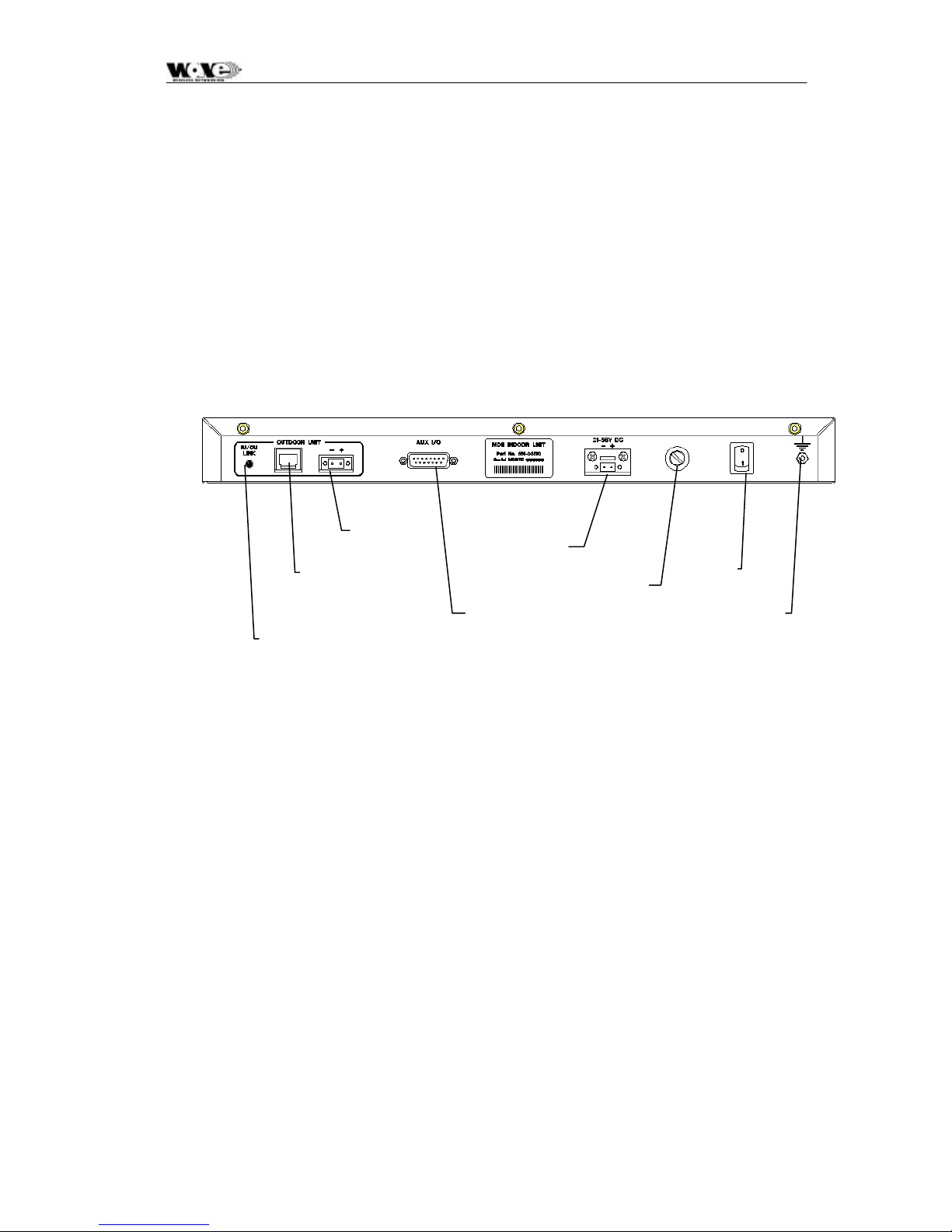
the front panel. Input Power, Auxiliary alarm and ‘IU/OU Interconnect’ interfaces are
located on the rear panel, suitable for rack installations.
IU/OU Data
Interconnect RJ45
IU/OU Link LED
IU/OU Power
Interconnect
DC In
Auxiliary IO
Fuse
Holder
ON/OFF
Switch
Ground
Terminal
The recommended installation procedure for the Indoor Unit is the following:
• Install the Indoor Unit in the rack.
• Earth the Indoor Unit.
• Connect the DC power supply.
• Connect Paylo ad data ports (front panel).
• Connect Auxiliary In/Out port (optional).
• Connect Service Channel (Wayside) serial port (optional).
• Connect the Element Manager port using the supplied cable (front panel).
4.2.2 Installing the Indoor Unit in a Rack
1. Slide the Indoor Unit into the 19" rack and secure to the rack using four M6 x
18 mm screws.
2. Earth the Indoor Unit by connecting the earth cable or strap between the
station earth and the earth stud on the Indoor Unit rear panel.
25
Page 28
SPEEDCOM SC5800 User Manual
4.2.3 Connecting a DC Power Supply
WARNING – See Section 8.4, Power Supply Equipments, page 59 for
specification of the power supply.
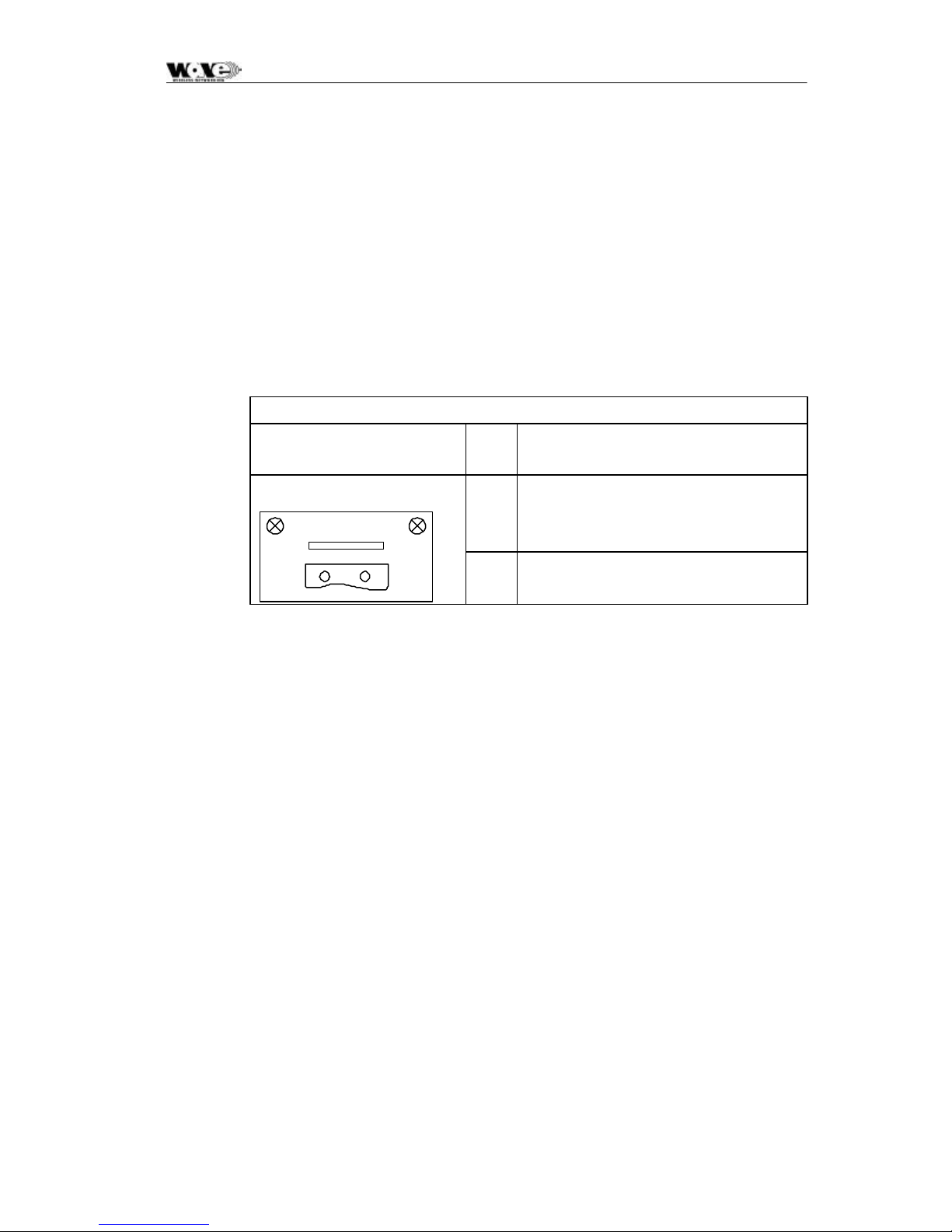
1. Observing the polarity of the supply, wire up the supplied power connector
cable plug and connect it to the DC supply (21 to 56 V) through a minimum 5
A circuit breaker.
2. Check the supply voltage using a multimeter.
3. Secure the connector screws to the unit.
DC Power Connector Pinouts
Indoor unit connector
Gray
2-pin Wieland Type 8213
DC
+-
Pin
No
+
-
Signal
DC POWER
DC POWER RETURN
26
Page 29

SPEEDCOM SC5800 User Manual
4.2.4 Balanced Payload Data
1. Assemble the (nE1) / (nT1) payload data input and output cable. See the
table below for Indoor Unit connector pin assignments.
2. Connect the payload data cable to the DB25 connector on the front panel of
the Indoor Unit.
D-Type
Payload
Data
Connector
Pin #
1 GND Earth N/A
2 RTIP1 1 RX +
3 RRING1 1 RX 4 GND Earth N/A
5 TTIP1 1 TX 6 TRING1 1 TX +
7 GND Earth N/A
8 GND Earth N/A
9 RRING0 0 RX +
10 RTIP0 0 RX 11 GND Earth N/A
12 TRING0 0 TX 13 TTIP0 0 TX +
14 TRING2 2 TX -
Pin Name Tributary Direction
15 TTIP2 2 TX +
16 GND Earth N/A
17 RRING2 2 RX+
18 RTIP2 2 RX19 GND Earth N/A
20 TTIP3 3 TX21 TRING3 3 TX+
22 GND Earth N/A
23 RTIP3 3 RX+
24 RRING3 3 RX25 GND Earth N/A
27
Page 30
SPEEDCOM SC5800 User Manual
4.2.5 Connecting Auxiliary In/Out (Optional)
The auxiliary in/out port is used to:
• Monitor switch-closure events using two isolated inputs.
• Control line connections using normally-open and normally-closed relay
outputs.
Connect the port:
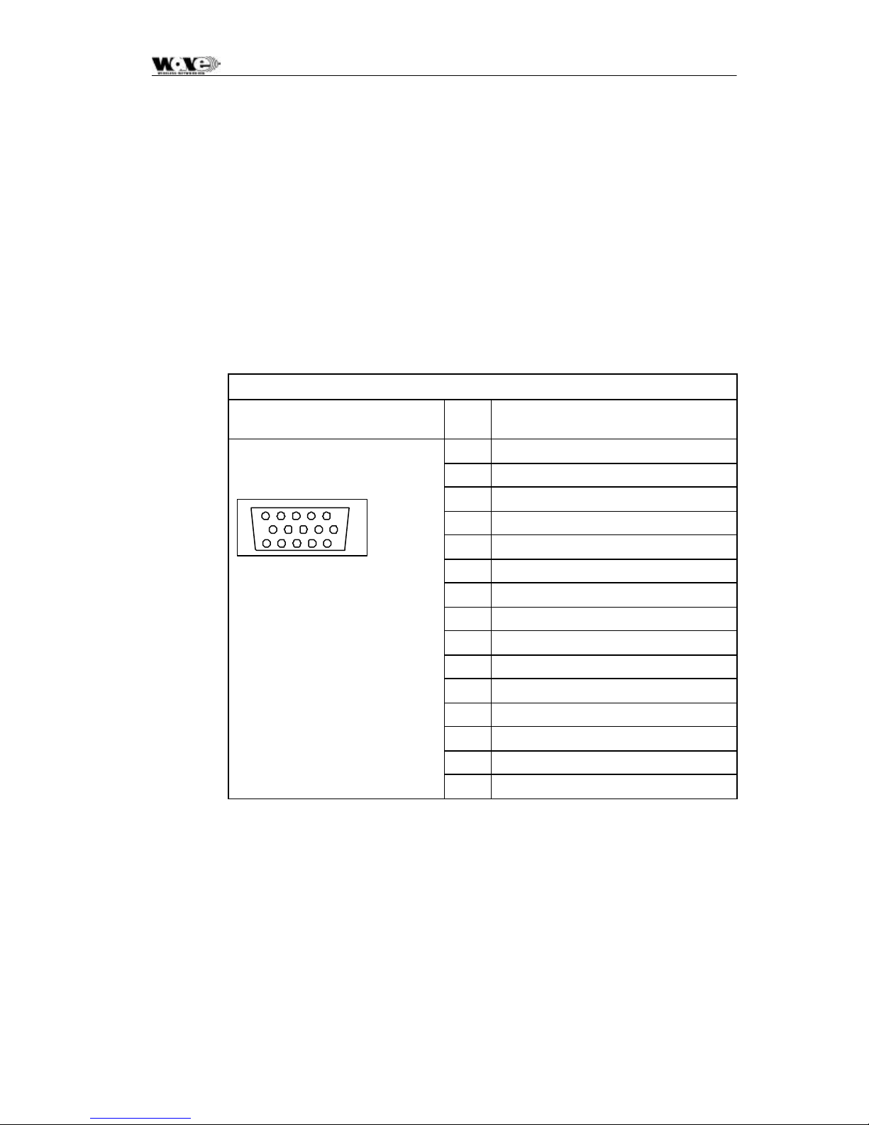
1. Assemble an auxiliary in/out cable using a High-density 15 way D-type mal e
connector according to connector pin assignments shown in Table 4.
2. Connect to the cable Indoor Unit auxiliary in/out connector.
3. Secure the connector using locking screws.
Table 4. Auxiliary In/Out Connector Pin Outs
Indoor unit connector Pin
Signal
No
15-pin High density D-type female
15
10
15
6
11
1 OUTPUT 1 COMMON
2 OUTPUT 1 NORMALLY-OP EN
3 OUTPUT 1 NORMALLY-OPEN
4 OUTPUT 1 NORMALLY-CLOSED
5 OUTPUT 1 NORMALLY-CLOSED
6 OUTPUT 1 COMMON
7 OUTPUT 2 COMMON
8 OUTPUT 2 COMMON
9 OUTPUT 2 NORMALLY-OP EN
10 OUTPUT 2 NORMALLY- OPE N
11 OUTPUT 2 NORMALLY- CLO SED
12 INPUT 1
13 INPUT 1 RETURN
14 INPUT 2
15 INPUT 2 RETURN
28
Page 31
SPEEDCOM SC5800 User Manual
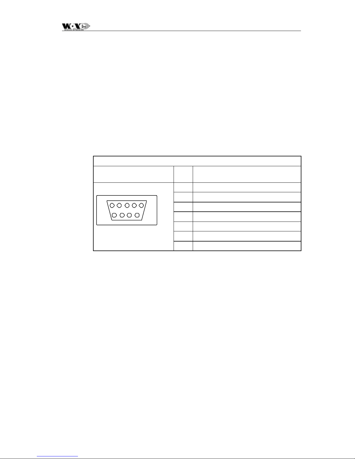
4.2.6 Connecting the Service (Wayside) Serial Channel (Optional)
This ‘clear’ serial channel can transport up to 115,200 bps across the radio link.
This channel does not interfere with the payload data channels. The port is
configured as DCE.
1. Connect the serial data interface cable to the Service channel connector on
the Indoor Unit rear panel. The supplied serial data cable can be used to
connect to this port after the software setup is completed.
2. See the table below for Indoor Unit connector pin assignments when a custom
cable needs to be assembled.
3. Secure the connector using locking screws.
Service Channel Connector Pinouts
Indoor Unit connector Pin
No
9-pin D-type Female Connector
15
2 TD
3 RD
4 DTR
69
5 GROUND
6 DSR
7 RTS
8 CTS
4.2.7 Connecting the Element Manager Port
The Element Manager port is used to connect the Indoor Unit to a PC/Laptop serial
port. This enables the Indoor Unit to be configured using the supplied NMS software
or controlled via a PPP-dialup connection. The port can be connected to using the
supplied serial data cable. The port is configured as DTE.
Signal
29
Page 32

SPEEDCOM SC5800 User Manual
4.3 Outdoor Unit
Before installing the SC5800 Outdoor Unit, ensure that a suitable mast is used for
the antenna and that the Outdoor Unit installation is firmly in position. The pole
diameter must be between 50 and 102 mm.
4.3.1 SC5800 Outdoor Unit
CAUTION – ENSURE THAT THE POLE IS GROUNDED FOR LIGHTNING
PROTECTION.
Follow these steps to install the SC5800 Outdoor Unit:
1. Install the system antenna.
2. Adjust the mounting bracket to be slightly bigger than the pole diameter.
3. Secure the mounting bracket to the pole.
4. Secure the Outdoor Unit to the bracket using the screws on each bracket.
5. Connect the Outdoor Unit to the pole electrically by connecting the earth
cable or strap between the pole earth and the Outdoor Unit earth point.
6. Connect the type-N RF output connector to the system antenna through an
in-line lightning protection unit in areas with lightning activity.
7. Cover the connectors using an ultra violet protective, self-vulcanizing tape.
4.3.1.1 RF Connection
1. The RF port is an N-type female connector.
2. The N-Type connector is used to connect to the antenna, typically using
coaxial transmission line.
3. 1/2" or 5/8” coaxial cables are recommended. Coaxial cable that is 7/8” or
larger can exhibit moding at 5.8 GHz and is not recommended for 5.8 GHz
radios.
4. Do not use right angle N-type connectors with the 5.8 GHz radios: they may
present high loss at 5.8 GHz.
5. Do not use low quality cables. Some cable types, such as RG-8, may have
too high a loss at 5.8 GHz.
30
Page 33
SPEEDCOM SC5800 User Manual
4.4 Interconnection Cable Installation
Follow these steps to install the Indoor Unit to Outdoor Unit interconnection cables.
CAUTION
DO NOT OVER TIGHTEN THE CABLE STRAPS ON THE CABLES AND DO
-
NOT FASTEN THE STRAP LOCKING MECHANISM OF THE CABLE STRAP
ONTO THE CABLES.
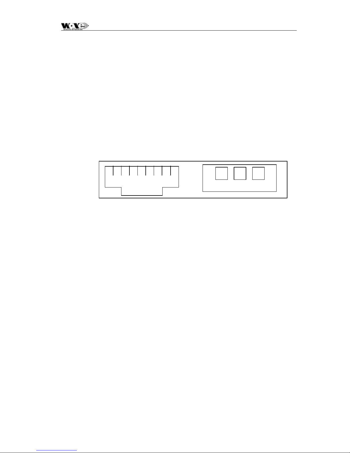
1. On the OU side, connect an RJ45 plug to the data cable. Place the RJ45
plug into the RJ45 socket in the Outdoor Unit connection box.
2. On the OU side, connect the DC power leads within the Outdoor Unit
Connection Box. Use the +Ve and Return connections.
18
RJ45 Socket
Return +Ve "Chassis"
3. Close the Outdoor Unit Connection Box Cover using a 2.5mm Allen key.
Make sure the rubber gaskets seal correctly over the power and data cables.
4. Using cable ties, secure the cable to the pole at regular intervals.
5. On the IU side, connect an RJ45 plug to the data cable. Place the RJ45 plug
into the RJ45 socket in the rear of the Indoor Unit.
6. On the IU side, connect the DC power leads to the supplied GREEN Phoenix
plug. Insert this plug into the green socket on the rear-panel of the IU.
7. The user can see that there is a suitable IU/OU data interconnection if the
‘IU/OU Link’ LED on the rear-panel of the IU is lit up green.
CAUTION
UNDO THE SCREWS OF THE “CONNECTION BOX” IN A UNIFORM
-
MANNER. THIS ENSURES THAT THE “CONNECTION BOX” GASKET
MATERIAL RELEASES STRESS UNIFORMLY AND DOES NOT LEAD TO
THE SECURING SCREWS BEING BENT DUE TO THE PRESSURE PLACED
ON THE CONNECTION BOX LID.
31
Page 34
SPEEDCOM SC5800 User Manual
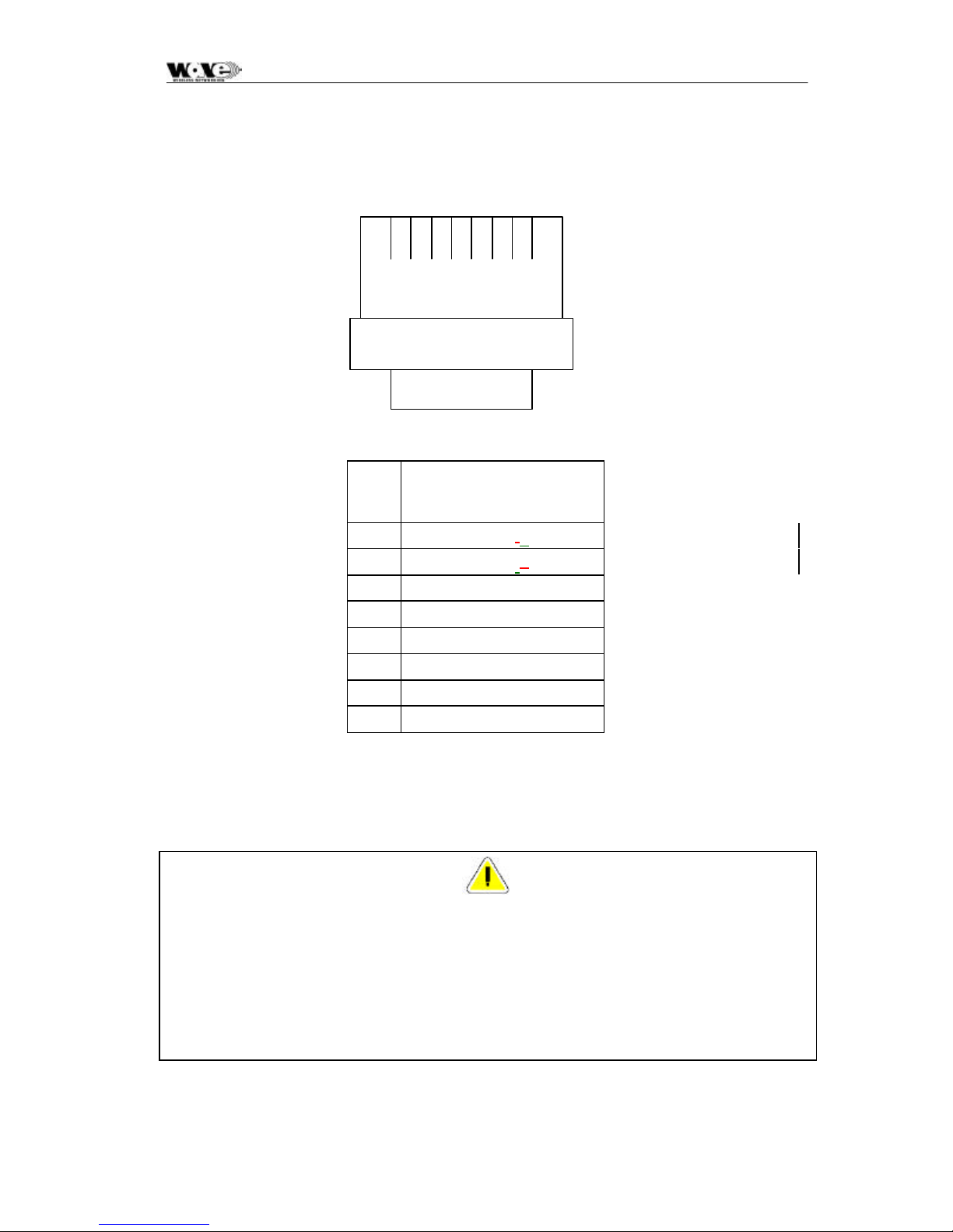
4.4.1 INTERCONNECTION CABLE WIRING DESCRIPTION
TOP VIEW (LOCKING
TAB UNDERNEATH)
18
RJ-45 PLUG
Pin DTE (on
INDOOR
DCE (on
OUTDOOR UNIT)
UNIT)
1 TxD+ RxD-+
2 TxD- RxD-+
3 RxD+ TxD+
4† TxC+ RxC+
5† TxC- RxC-
6 RxD- TxD7† RxC+ TxC+
8† RxC- TxC-
NOTES
• † Vers i o n 2 releases of the hardware (indoor and outdoor units) cannot be used
interchangeably. For version 2 IU & OU hardware, use of TxC+, TxC-, RxC+, RxC- falls
away and only two (2) twisted pairs are required.
• The important point is that the interconnect cable is wired as a standard 1-to-1 Ethernet
patch cable.
• Pairs 4/5 and 7/8 are not required or used on Version 2 products.
32
Page 35

SPEEDCOM SC5800 User Manual
5 ANTENNA ALIGNMENT AN D SOFTWARE SETUP
This chapter describes the procedure for software setup and antenna alignment. The
setup is done with a PC running the supplied NMS software. For more information,
see Section 6, NMS Software, page 39.
5.1 Installation Equipment Required
The following tools and instruments are required for software setup and aligning the
antenna:
• RSSI test cable
• Voltmeter
• Spanner, also called a Wrench, (see appropriate details in installation chapter
depending on the antenna being used)
• PC with NMS software and supplied serial data cable.
• Binoculars (optional) used for locating the far end site. This will assist in the
antenna alignment operation.
• GPS or Standard Compass (optional) used for locating the far end site. This
will assist in the antenna alignment operation.
• Bit Error Rate Tester and connecting leads.
5.2 Information Required
You should know:
• Proposed frequency channel plan for each station.
• Expected receive level based on the chosen system configuration and a
pathloss analysis.
5.3 Antenna Alignment
5.3.1 Introduction
The SC5800 should be installed on both sites before alignment st arts. Perform the
following steps at both stations:
1. Switch the Indoor Unit power ON.
2. Install and run the SC5800 NMS Software application.
3. Configure the radio channel plan as required.
4. Set the transmitted power to maximum.
5. Perform a RF loopback test at each site before starting the alignment
procedure.
33
Page 36

SPEEDCOM SC5800 User Manual
5.3.2 Alignment Procedure
1. Locate the far site and point the antenna to the antenna at the far site, as
accurately as possible using binoculars or a compass.
2. Connect the multimeter to the RSSI connector on the Outdoor Unit using the
supplied RSSI test cable and set the multimeter to measure volts.
3. Check the RSSI level and refer to the figure below for received power level.
4. Align the antenna until the maximum RSSI is attained.
5. Secure the antenna.
6. Measure the RSSI level and record the value (see Section 5 .7, SC5800Test
Record, page 37).
7. Compare with the value with that calculated for the link (i.e., using the
pathloss calculation done when planning the link).
Figure 5. Typical Version 2 OU RSSI Voltage as a function of RF input power
level
-80dBm Average 0.436 ± 0.029 V: MIB RSSI 95 ± 1 dBm (see comment below)
-30 dBm Average 1.333 ± 0.047 V: MIB RSSI 54 ± 2 dBm (see comment below)
The MIB lists a dBm value representative of the received signal level. The value
detected is representative of the level that would be measured should a CW signal
be input at the Outdoor Unit's Diplexer RF Port - a Spread Spectrum signal will
appear to be 20 dB lower. The NMS makes an adjustment for this by using a 20 dB
offset (addition to the Indoor Unit MIB-indicated value).
The front panel RF Link LED, the Received Signal Strength Indicators (RSSI : on
NMS, via SNMP or as an Electrical signal on the Outdoor Unit), Carrier-detect
(NMS, SNMP) and Frame Lock (NMS, SNMP) indicators are available to assist with
link installation and alignment.
The front panel RF Link LED, the Received Signal Strength Indicators (RSSI: on
NMS, via SNMP or as an Electrical signal on the Outdoor Unit), Carrier -detect
(NMS, SNMP) and Frame Lock (NMS, SNMP) indicators are available to assist with
link installation and alignment.
5.3.3 Set Transmitted Power Level
It is good practice to match received power levels by adjusting transmitted powers if
co-located systems are being installed. This is important to avoid interference
between co-located systems. An attenuator can be fitted between the Outdoor Unit
and the antenna if the power level cannot be sufficiently reduced. The dBm output at
the OU N-type connector (socket) levels are set via the NMS or using a SNMP
Management application.
34
Page 37

SPEEDCOM SC5800 User Manual
5.4 Software Setup
Refer to Section 6, NMS Software, page 39, for setting up the following:
• Payload interface.
• Service Channel (Wayside) serial port.
• Auxiliary in/out port.
• General link parameters.
5.5 Functional Test
After completing the physical installation of the Indoor Units, antennas, Outdoor
Units and the interconnection cables, you need to commission the system. This
procedure describes how to set up the minimum requirements for successful
SC5800 system operation.
5.5.1 Link Bit Error Rate Performance Test
To start: when the link is setup correctly, the RF Link LEDs on both IUs on both
sides of the RF link should be GREEN.
When the link has been setup and is running error-free:
1. Clear the Indoor Unit Log using Reset Button Position ‘2’
2. Clear the Indoor Unit Errors using Reset Button Position ‘1’
Perform a link bit error rate performance test as follows:
• Connect a bit error rate tester to the payload interface of the link.
• Run data over the link for a period of 24 hours.
• Record the BER.
• Record the LED statuses.
Check the Indoor Unit Packet Error Results via the NMS or via SNMP access to the
In door Unit MIB – for the NMS, right-click on the antennas in the NMS for either side
of the link and select the “Diagnostic/Error Monitor” option. Record the results by
saving the data to a file. For SNMP access, use a MIB Browser and check the
mdrmteRFLi nkPerf and mdrmteG826 Performance groups.
Record all results on a test record. See Section 5.7, SC5800 Test Record, page 37
for an example.
35
Page 38
SPEEDCOM SC5800 User Manual
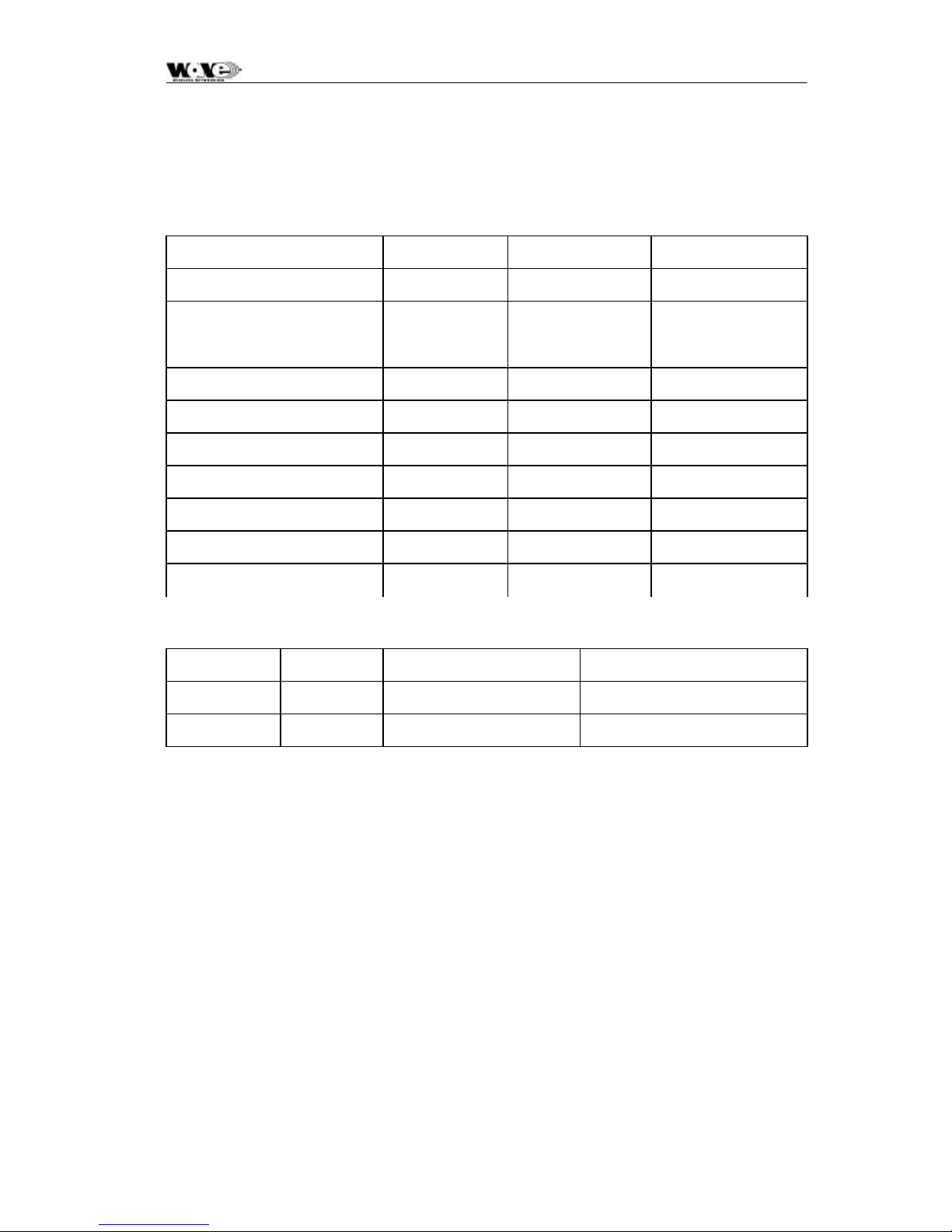
5.6 SC5800 Installation Record
Parameter Unit Site A Site B
Site Name
Antenna Type
RF cable length Meters
Lightening protection unit Yes/No
Interconnecting cable length Meters
Outdoor Unit serial number
Indoor Unit serial number
Outdoor Unit earthed Y es/No
Indoor Unit earthed Yes/No
Power Supply Volts DC/AC
Date Name Signature
Performed by
Approved by
36
Page 39
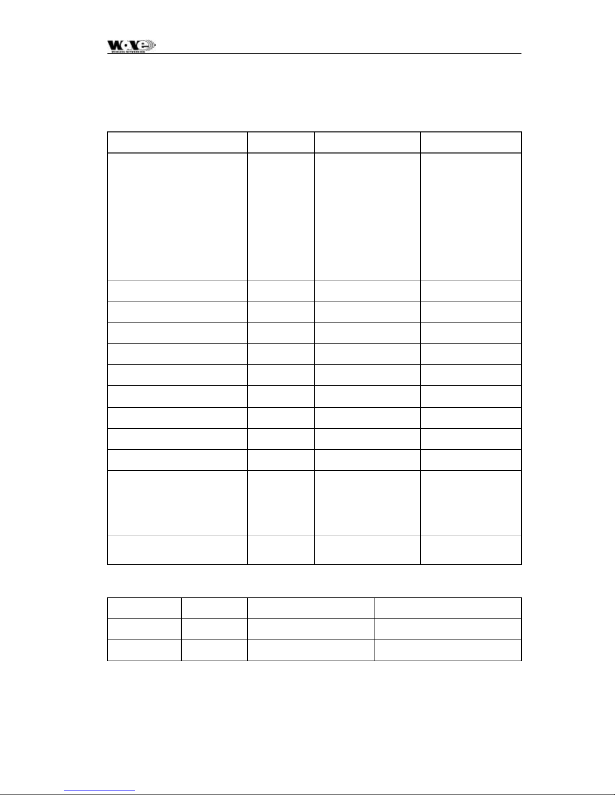
SPEEDCOM SC5800 User Manual
5. 7 SC5800 Test Record
Parameter Unit Site A Site B
Frequency channel plan:
Transmit
Receive
Transmitter output power dBm
Receiver input level (ON) Volts
Receiver input level (ON) dBm
Receiver input level (OFF) Volts
Receiver input level (OFF) dBm
Calculated input level dBm
Fade margin dB
Frame Lock indicator Color
A/B/C/D
A/B/C/D
If D – List
Transmit and
Receive
Frequencies
[MHz]
Fixed attenuator dB
BER-test
Alarm Indicators Clear
Date Name Signature
Performed by
Approved by
Hours
BER
(Yes/No)
37
Page 40

SPEEDCOM SC5800 User Manual
38
Page 41

SPEEDCOM SC5800 User Manual
6 NMS SOFTWARE
6.1 Introduction to the Network Management System
The purpose of the Network Management System, hereafter called the NMS, is to
allow you to configure, manage or interrogate the following primary functional
elements of a Digital Radio Link (Local or Remote Stations within the link):
• Indoor Unit
• Ou td oor Unit
The NMS is a PC-based software package that provides you with a graphical
interface that is used to perform on-site element management of a Microwave Digital
Radio (SC5800) System. It allows you to configure, manage and interrogate the
SC5800 System by selecting various menus and options.
It provides extensive management functions on site and, via the microwave radio link,
can be used to access the remote SC5800 station.
The hardware as well as the software constituting the NMS is collectively called the
NMS Terminal.
The NMS Terminal is the principal system support equipment associated with the
SC5800 System for system installation and commissioning.
It connects to a designated NMS Terminal port (labeled Element Manager) on the
front panel of the Indoor Unit of a SC5800 Station installation, by means of a serial
data interface (this cable is supplied in the IU box).
The NMS communicates with SNMP agent software that is contained in each
SC5800 Indoor Unit. The NMS communic ates with the agent’s software: the software
enables a unit to interpret MIB (Management Information Base) commands via SNMP
(Simple Network Management Protocol).
6.2 General Information
1. To select a button/option, simply click the appropriate button/option .
2. Move the mouse pointer to the different areas of the screen. When the pointer
changes into a hand, this indicates that the area can be activated by a left
mouse button click. In some cases (opto inputs, relays, payload interfaces),
hold the mouse hand cursor over the particular area of the screen and a hint
appears indicating the state associated with the selected item. If the pointer
changes to vertical bar, then the field may be edited if clicked.
3. The main screen has pull -down menus that are activated by clicking on the
words of the menu (menu items).
39
Page 42

SPEEDCOM SC5800 User Manual
4. A general help facility is available by clicking on the Help button on the Main
screen. This opens the help file for the Network Management System. From
here, you can search for a particular topic using the Index facility or you can
use the Find facility to search for key words connected to the specific
information required.
6.2.1 Microwave Digital Radio
A SC5800 link consists of at least one complementary pair of SC5800 stations that
may be extended over longer distances by linking further station pairs in a multiplehop configuration. A single SC5800 station comprises an Indoor Unit and an
Outdoor Unit interconnected by a data cable (CAT5) and a 2 -core DC supply cable.
40
Page 43
SPEEDCOM SC5800 User Manual
6.3 Main Screen
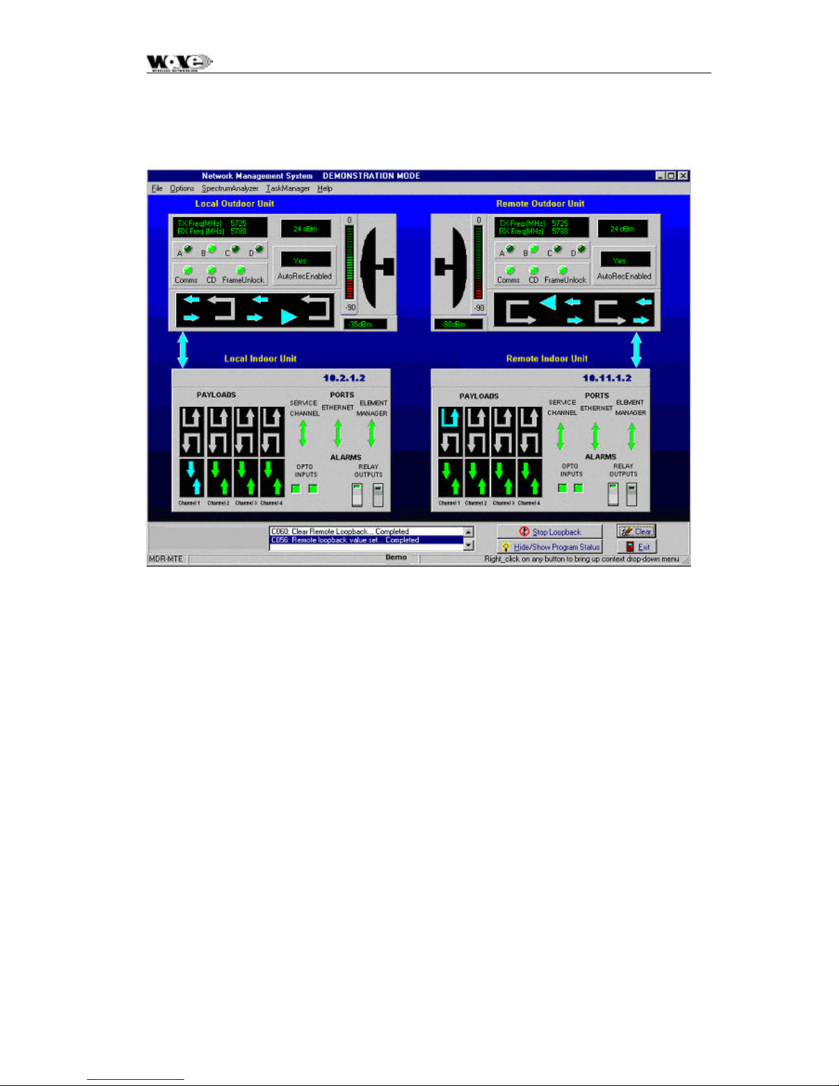
Figure 6. RSSI as a function of RF input level
This screen displays the names of the stations/sites, their IP addresses and allows
you to view or edit the parameters and status for the entire station. Indoor Unit and
Outdoor Unit de tails are accessed by using the mouse to select the Indoor Unit and
Outdoor Units of the local or remote sites.
Note that if the local Indoor Unit is offline, all controls for both station IUs and OUs
are 'grayed out' and thus unavailable. If the Outdoor Unit is offline and the Indoor
Unit is online, then only the Outdoor Unit controls are 'grayed out' and unavailable.
The Main screen shows a local station on the left hand side of the screen and a
remote station on the right hand side of the screen.
The Main Menu area provides pull-down menus and controls that allow you to
configure and monitor system link parameters and to perform basic tasks.
The station elements are displayed initially with no colors, but the controls in the
blocks change colors when the NMS attempts to communicate with the link’s
primary elements.
The control buttons on the screen are short-cuts to MIB elements in the Indoor
Units.
Move your mouse pointer to the required area of the screen and when the mouse
pointer changes into a 'hand', click the right mouse button to display more detailed
information. Click the left mouse button to activate relays and loopbacks.
41
Page 44

SPEEDCOM SC5800 User Manual
6.3.1 Link Elements Areas
The Link Elements Areas on the Main Screen show an abbreviated status of the
Indoor and Outdoor Unit interfaces. Move your mouse pointer to each block until a
hand appears and click the right mouse button (right click) to see more information
on each element.
If both Stations are online, the status bar at the bottom of the screen shows that the
stations are being polled. If there is no communication with the remote side, the
remote station will be grayed. If there is no communication with the local side’s
Outdoor Unit, it will be gray.
Display Indicators
• A GREEN status indicator shows that there are no current alarms or errors.
• A YELLOW status indicator shows that there was a historic alarm condition.
• A RED status indicator shows that there is a current alarm condition.
The main screen shows a RSSI (Received Signal Strength Indication) bar graph in
dBm.
42
Page 45

SPEEDCOM SC5800 User Manual
6.4 NMS Menus
6.4.1 Main Screen Menus
The following pull-down menus are available from the Main menu:
Menu Sub-item Result
File
Options
Exit Exit from NMS.
Communications Allows setup of which communications port is
used on the PC or Laptop for communication
with the Indoor Unit via the front panel Element
Manager Serial Port.
Local Trib Code
Remote Trib Code See above.
Local User
Configuration
It is possible to purchase upgrades for E1/T1
Indoor Units (upgrades to 2E1/T1 or 4E1/T1).
The user contacts the factory and provides the
Indoor Unit Bar Code number details. The
factory then supplies a “Tributary Code”, unique
to the Indoor Unit, which is entered using the
MIB (Version 2 products) or using the NMS
(Version 2 product).
Allows the user to set the access control
settings for the local station equipment to allow
the user to log on as an ‘Administrator’ with full
read/write configuration access or with ‘Read only’ access. (Note: This option is only available
if the IU firmware has been supplied with securefeatures activated – the default is NOT to have
this feature activated).
Spectrum
Analyzer
Remote User
Configuration
Allows the user to examine the RF spectrum
Allows the user to set the access control
settings for the remote station equipment to
allow the user to log on as an ‘Administrator’ with
full read/write configuration access or with ‘Readonly’ access. (Note: This option is only available
if the IU firmware has been supplied with securefeatures activated – the default is NOT to have
this fea ture activated).
using a RSSI (received signal strength indicator)
value measured in the Outdoor Unit. If
interference exists, this feature allows the user to
examine the spectrum and decide w here to set
the transmit and receive frequencies for the local
and remote stations.
43
Page 46

SPEEDCOM SC5800 User Manual
6.4.1.1 Exiting from the NMS: File/Exit
You can exit from the NMS as follows:
Click on the Exit option from the File pull-down menu on the Main screen.
You are prompted for confirmation of the shutdown – answer OK or Cancel to this
prompt.
6.4.1.2 Communications
This menu item allows you to configure the following NMS communications
parameters:
• Serial Port
• Polling Cycle
The users can either:
Use the Load Defaults option or change to the required settings and then use the
Apply Changes button.
Use the Exit button to exit without any changes being made.
6.4.1.2.1 Serial Port
Configure the serial port as follows:
1. Select Communications from the menu on the main screen.
2. Select the required port: COM1, COM2, COM3 or COM4.
6.4.1.2.2 Polling Cycle
Set the polling cycle (minimum 3 seconds). This determines how often the
information is updated.
6.4.1.3 Local User Configuration
Allows the user to set the access control settings for the local station equipment to
allow the user to log on as an ‘Administrator’ with full read/write configuration access
or with ‘Read -only’ access (only available with “security-enabled” versions of Indoor
Unit firmware).
The user enters a ‘Username’, ‘Password’, ‘Access level’ and activates the user via
an ‘Active’ input field.
With ‘Administrator’ access, the user can add new users.
Use the Apply Changes button once the changes are to be made in the Indoor Unit.
Use the Exit button to exit without any changes being made.
44
Page 47

SPEEDCOM SC5800 User Manual
6.4.1.4 Remote User Configuration
This applies to the same directions above (that is, Section 6.3.1.3, Local User
Configuration, page 44) but controls access to the remote station’s MIB.
6.4.2 Main Screen Short-cut Buttons
Short -cut buttons are provided to allow quick access to the above menu items.
6.5 Indoor Unit Configuration
The Indoor Units have graphical interface controls that allow you to configure the
following items:
• Payload Data Interface Port
• Service Channel Port
• ‘Loopback to Line’ and ‘loopback to RF Link ’
• Opto Inputs
• Relays
Payload is from the user’s ‘line’ equipment to the Indoor Unit Payload Data DB25
connector and RF Link is from Antenna to Antenna.
Right-click on the Indoor Unit to get the following opt ions
• Time/date entry
• Station Status
• Station Properties
• Station Info (Serial number, software version, bootkernel version)
• View Event Log
• Maintenance
6.5.1 Controls
6.5.1.1 Payload Data Interface Port
A label/name can be assigned to any of the payloads.
6.5.1.1.1 E1 Port Line Code
Default setting is HDB3. However, it can be set to either HDB3 or AMI.
45
Page 48

SPEEDCOM SC5800 User Manual
6.5.1.1.2 T1 Port Line Code
Default setting is B8ZS. However, it can be set to either B8ZS or AMI.
6.5.1.2 Payload Error Monitoring
Term Name Description
AIS Alarm Indication
Signal
LOS Loss of Signal This is a loss of signal detected on the input to the
6.5.1.3 Service Channel Port
The service channel serial port provides a means to send asynchronous data across
the link to the far side service channel port. Service channel ports can be connected
back-to-back (i.e., Remote to Local) at a remote site so as to extend the channel in
a multi -hop network. The service channel data is multiplexed with IP data onto the
RF overhead link. Priority is given to IP data.
• Use the Load Defaults option or change to the required settings and then
use the Apply Changes button.
This is an all 1’s detection, incoming to the
equipment on the payload tributaries. Note that
there is independent monitoring for AIS on each of
the 4 tributaries.
payload data port tribu taries. Note that there is
independent monitoring for LOS on each of the 4
tributaries.
• Use the Exit button to exit without any changes being made.
6.5.1.3.1 Baud Rate
Default setting is 115200 bit/s (Ver 1, 2) .
6.5.1.3.2 Data Width
Default setting is 8 bits.
6.5.1.3.3 Parity
Default setting is None.
6.5.1.3.4 Flow Control
Default setting is None.
6.5.1.3.5 Stop Bits
Default setting is 1 Bit.
6.5.1.4 Relay Scripting (NA for Version 2 releases)
Note: THIS MANUAL ADDRESS FEATURES SPECIFIC TO VERSION 2 OF THE
SPEEDCOM SC5800 PLEASE IGNORE REFERENCES TO OTH ER VERSIONS.
46
Page 49

SPEEDCOM SC5800 User Manual
Configure the various alarms that will switch on Indoor Unit relays as required. There
are two relays on each Indoor Unit. Each relay can be programmed to switch on
based on the occurrence of Payload or RF Link errors detected in the LOCAL/NEAR
and/or REMOTE/FAR Indoor Units. The user can visually select those errors that
will trigger the respective relays.
The following built -i n test status can be monitored on a link:
RF Link
• Use the Apply Changes button to change settings.
• Use the Exit button to exit without any changes being made.
Link Unavailable
Frame Unlock
Minor PER Exceeded
ESR Exceede d
LOS Payload Interface
AIS
6.5.1.5 Indoor Unit Loopback Controls
These controls allow you to set the loopbacks on the payload data.
• IU Loopback to Line - Used to loopback the data on the payload interface so
that incoming user payload data is sent straight back to the user. The
payload data does not go out over the RF link.
• IU Loopback to RF Link - Used to loopback the payload (Indoor
Unit)/Out door Unit data so that payload data arriving over the RF link is looped
and sent back across the RF link.
Perform a loopback as follows:
1. Select the Loopback Type by choice of arrows on the IU being tested.
2. Select the Loopback Timeout Time (in seconds). If enabled, the Loopback
state will cancel after Time seconds and the unit will return to normal
operation.
3. Click on the Loopback Timeout Enable checkbox.
4. Click on the Apply Changes button.
47
Page 50

SPEEDCOM SC5800 User Manual
6.5.2 Menu Items
6.5.2.1 Date/Time Entry
In this menu, the user has the option of entering the:
• Date (change date using the calendar display)
• Time (change time using the spin button on the right -hand side of the control or enter
manually).
• The user had the option of ‘fetching’ the date and time from the PC or Laptop and using t his
information.
• Use the Apply Changes button once the update in the Indoor Unit is to be made.
6.5.2.2 Station Status
6.5.2.3 General Status Indicators
These errors occur during the phase of continuous error checking. Errors are
latched until the operator clears them on the NMS.
The following is a list of possible error indicators as well as the possible faults and
corrective actions to solve each error.
Error Displayed Possible Faults and Corrective Actions
General Faults
Outdoor Unit Not
Responding
Outdoor Unit
Comms Error
Wayside Port
Comms Error
• The Outdoor Unit simply doesn't respond to any messages sent to it
by the Indoor Unit. The Outdoor Unit could possibly be damaged or
the cables to the Outdoor Unit are disconnected from the Indoor Unit
or damaged.
• Message from Outdoor Unit too long (data corruption).
• Received message frame invalid – the Outdoor Unit messages follow a
strict data link layer frame protocol. There could data corruption.
• Partial message received from Outdoor Unit - remainder did not arrive
in time (Outdoor Unit switched off?).
• CRC Error – data corruption.
• Software queuing/buffering errors in the Indoor Unit firmware.
• Wayside port queue overruns - too high data rates or failed overhead
link.
• Comms Error - errors caused by Rx Overrun (Indoor Unit processor
could not service the received characters fast: too high data rates),
parity error if odd or even parity enabled (data corruption or incorrect
configuration), framing error (no valid stop bit where one was expected
- invalid baud rate or data width or parity configuration or data
corruption) or break detected (line shorted causing permanent break or
corruption).
48
Page 51

SPEEDCOM SC5800 User Manual
Overhead Link
Comms Error
• Overhead PPP link error: the buffering system of the overhead link
cannot process data fast enough and received messages have been
discarded (the software cannot process the data fast enough).
Ethernet Comms
Error
• The buffering system of the interface cannot process data fast enough
and received messages have been discarded (the software cannot
handle the data fast enough).
Element Manager
Comms Error
• Message from PC or laptop too long (data corruption).
• Software queuing/buffering errors in the NMS firmware.
Alarm 1 on • A digital optically isolated input used for general site alarm monitoring
(Auxiliary Input 1).
Alarm 2 on • A digital optically isolated input used for general site alarm monitoring
(Auxiliary Input 2).
6.5.2.3.1 Power-up Self Test Indicators
The following is a list of errors that can occur during the power-up phase of
operation. These errors may only be cleared by switching the Indoor Unit off and
then on again. The list also describes the possible faults and corrective actions to
solve each error.
Error Possible Faults and Corrective Actions
FLASH The Application FLASH memory test failed. Only a faulty Application Flash
device can cause this fault and the Application Flash device will have to be
replaced.
DRAM Error The DRAM test failed. Only a faulty DRAM device can cause this fault and
the DRAM will have to be replaced.
SRAM Error The battery-backed up SRAM test failed. Only a faulty SRAM device or
battery can cause this fault and the Battery and/or SRAM will have to be
replaced.
Watchdog Reset Software error. Please contact the supplier. Processor triggered a
watchdog restart because watchdog is no longer being toggled by the
application. Either the application has become too overloaded or this is a
software or design fault.
Hard Reset A hardware reset was performed. This is an indication of the last reason for
a reset and does not constitute a fault condition.
Unknown Reset Another reset detected by the Indoor Unit’s microprocessor (other than
Watchdog and Hard Reset) was performed. This is an indication of the last
reason for a reset and does not constitute a fault condition.
Line Interface
Error
The line interface transceiver is not responding as expected and is most
likely faulty. The transceiver is programmed for operation and then checked
to see that the values programmed are valid (read correctly).
FPGA The FPGA register interface is not responding correctly and is most likely
faulty. The FPGA is programmed for operation and then checked to see
that the values programmed are valid (read correctly).
Real Time Clock The Real Time Clock (RTC) is not responding correctly and is most likely
faulty. The RTC is programmed for operation and then checked to see that
the values programmed are valid (read correctly).
Note: Use the Clear button to clear alarm indicators.
49
Page 52

SPEEDCOM SC5800 User Manual
6.5.2.4 Station Properties
In this menu, the user has the option of entering the:
• Indoor Unit Station name
• IP address of the Indoor Unit
• Netmask
Note: Use the Apply Changes button once the update in the Indoor Unit is to be made.
6.5.2.5 Station Info
• This information allows you to view the build state details of the primary
hardware and software components of the selected Indoor Unit. Information
provided is read from the Indoor Unit microprocessor.
• Serial Number (Programmed into the Indoor Unit at time of manufacture),
• Software Version (Programmed into the Indoor Unit during any software
upgrade) and
• Bootkernel Version Number (Programmed into the Indoor Unit at time of
manufacture).
6.5.2.6 Indoor Unit Event Log
This screen is used for the viewing of the event log file. In the event of a persistent
field fault, it will be useful for you to save the logged data file and send it (with the
faulty unit) to the repair department to assist in the repair of the unit. There is a
maximum of 100 records stored in the Indoor Unit (one filled, earlier records are
discarded in favor of newer records). The event log file is displayed from oldest to
youngest (i.e., ascending order by time). The log file columns are:
• Date – the date of the event dd-mm-yyyy.
• Time – the time of the event in hh:mm:ss.
• Type – the type of event.
• Event – a text description of the event itself.
Notes:
• Use the Clear Log button to clear the log in the Indoor Unit.
• Use the Refresh button to collect the log from the Indoor Unit.
• Use the Save button to save the log on the NMS PC or Laptop platform.
• Use the Exit button to exit the Event Log menu.
50
Page 53

SPEEDCOM SC5800 User Manual
6.5.2.7 Maintenance
This screen provides the ability to upgrade the Indoor Unit firmware on the local/near
Indoor Unit only.
The user selects the file to be uploaded using the Select File button. A file
selection dialogue is presented which provides a means to retrieve the file from any
directory on any drive.
Once the file is selected, the following information is displayed on the screen:
• Application version - the Indoor Unit application code software version
number as read from the Indoor Unit application).
• Date and time - the Indoor Unit application code software date as read from
the Indoor Unit application.
• Bootkernel version - the Indoor Unit boot kernel code software version
number as read from the boot kernel.
Upload Status box
Used to display the steps being undertaken during the programming and verification
process. As the upload process proceeds, the user is informed of progress.
Verification of upload is done once the file has been uploaded into DRAM.
Thereafter, the data is loaded into ‘Application Flash’. The latest version is uploaded
into one ½ of the flash device. The other half maintains the old version. In this way,
there is an option to revert to the old version should there be an upload problem.
6.5.2.7.1 Programming an Indoor Unit
This procedure allows you to program factory-supplied firmware into the Application
Flash IC on the Indoor Unit. Proceed as follows:
1. Switch off the Indoor Unit. Run the NMS application and connect to the Indoor
Unit via the Element Manager Port.
2. Select the file to be uploaded into the Indoor Unit.
3. Switch on the Indoor Unit.
4. The upload process will proceed and the user is informed of the progress via the
status box.
5. Once complete, the IU verifies the program code is valid.
6. Once verified, the data is transferred into the IU’s Application Flash.
7. Once the code is programmed, the Indoor Unit application is restarted by the
boot kernel.
51
Page 54

SPEEDCOM SC5800 User Manual
6.6 Outdoor Unit Configuration
6.6.1 Controls
6.6.1.1 Loopback Controls
These controls allow you to set the loopbacks on the payload data.
• OU Baseband Loopback - Used to loopback the data at baseband
processor level in the Outdoor Unit so that incoming user payload data is sent
back to the user via the IU/OU interconnection data cable.
• OU RF Loopback - All RF data sent out of the Local Indoor Unit to the
Outdoor Unit is looped back at the output stage of the Outdoor Unit and
returned to the Indoor Unit.
Perform a loopback as follows:
1. Select the Loopback Type by choice of arrows on the OU being tested.
2. Select the Loopback Timeout Time (in seconds). If enabled, the Loopback state
will cancel after Time seconds and the unit will return to normal operation.
3. Click on the Loopback Timeout Enable checkbox. If not enabled, then only the
NMS can cancel the loopback condition.
4. Click on the Apply Changes button.
6.6.2 Menu Items
6.6.2.1 Station Configure
The current Outdoor Unit parameters for Channel plan, Transmit Power and
Autorecovery are displayed. All Outdoor Unit operational parameters are stored in
the Indoor Unit. The Outdoor Unit is unaware of what it has been programmed to do.
The operational parameters are programmed automatically after a power up.
This screen allows you configure the following Operational Outdoor Unit
parameters:
• Frequency channel Plan.
• Transmit Power.
52
Page 55

SPEEDCOM SC5800 User Manual
6.6.2.1.1 Frequency Channel Plan
The SC5800 Radios operate in the 5.725 GHz to 5.850 GHz ISM frequency band.
The SC5800 has predefined frequency channel plans (termed A, B, C and D).
6.6.2.1.2 Transmit Power
The Transmit power ranges from 2 to 24 dBm. There is also a mute setting.
6.6.2.1.3 Autorecovery
This feature is used if the user is installing a link from one side and there is no
technical staff assistance on the opposite side of the link. It mitigates against the
link failing and not being able to be re-established.
If autorecovery is enabled, the required operational RF parameters are programmed
into the Outdoor Units by the local and remote Indoor Units. If communication
between the two Indoor Units has not reactivated within 5 seconds, the previous
(working) ‘default’ RF parameters are programmed into the respective Outdoor Units.
6.6.3 OU Station Info
The OU Station Info screen provides a brief report of the build state of the Outdoor
Unit:
• Serial number – loaded into the Outdoor Unit at time of manufacture.
• Software version – loaded into the Outdoor Unit at time of manufacture.
• High Band Transmitter – affects the way the channel plan is implemented on
the Outdoor Unit.
• Low Band Transmitter – affects the way the channel plan is implemented on
the Outdoor Unit.
• FCC Regulations (None, FCC, Other).
6.6.4 Outdoor Unit Status
This screen allows you to view the following Outdoor Unit status information:
• Last Restart. This indicates the reason why the Outdoor Unit restarted (e.g.,
Power On, Watchdog Timeout).
• OU Lock Detect Status: indicates if there is a loss of lock of the IF, Transmit or
Receive path phase-locked oscillators in the OU.
53
Page 56

SPEEDCOM SC5800 User Manual
6.7 RF Link Error Status Monitoring
Selected by right-clicking the relevant antenna and choosing the Diagnostics/Error
option.
6.7.1 RF Link Status
Link Unavailable The RF Link is considered not available (see Link Availability definition on
next page).
Frame Unlock RF link only. It looks at data received from the link. If the link is quality is
poor ( i.e., high PER at the RF level, ‘Frame Unlock’ is the result). AIS is
sent from the transceiver (from link direction) as long as ‘Frame Unlock’ is
true and no reliable data is available.
Packet Error Rate
Fault
ESR Exceeded RF Errored Second Ratio has been exceeded due to Packet errors on the
SESR Exceeded RF Seriously Errored Second Ratio has been exceeded due to Packet
BBER Exceeded RF Background Block/Packet Errors Ratio has been exceeded due to
Default RF
Parameters
Activated
The PER Monitoring has been enabled and the Instantaneous PER has
exceeded the configured PER Fault Threshold for the RF link.
RF link.
errors on the RF link.
block errors on the RF link.
The Operational RF parameters were programmed into the Outdoor Unit by
the local and remote Indoor Units. Communication between the two Indoor
Units has not reactivated within 5 seconds. To recover communication the
Indoor Unit has selected the ‘Default’ RF parameters and programmed the
Outdoor Unit with them.
6.7.2 Packet Error Rate Thresholds
Packet error rate (PER) is calculated as the ratio of the number of uncorrectable
blocks over the number of blocks transmitted per second. Three PER thresholds
are provided for each monitored link, these are:
• Minor PER Threshold – this threshold defaults to 0.0002 and triggers an alarm
if the calculated PER exceeds this value.
• Major PER Threshold – this threshold defaults to 0.02 and triggers an alarm if
the calculated PER exceeds this value.
• Fault PER Threshold – this threshold defaults to 2.0 and triggers an alarm if the
calculated PER exceeds this value.
54
Page 57
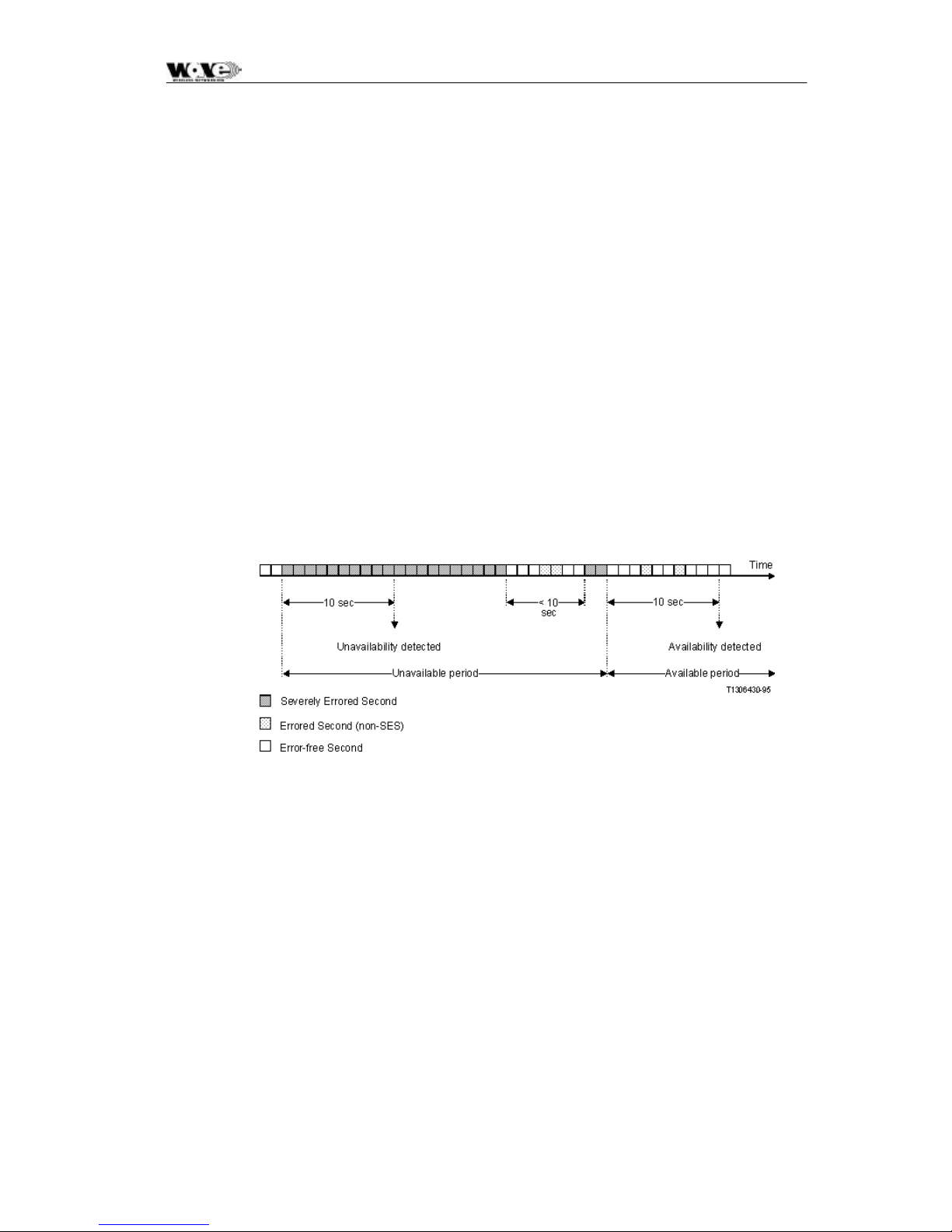
SPEEDCOM SC5800 User Manual
6.7.2.1 G.826 Thresholds
Three G.826 thresholds are provided for each monitored link. Each of these ratios is
calculated once every second and will trigger a fault condition if the ratios exceed the
programmed thresholds that are:
• Errored Second Ratio Threshold – this threshold which defaults to 4 X 10 -2
triggers an alarm if the calculated ESR exceeds this value over the measurement
period (Report Time).
• Severely Errored Second Ratio Threshold – this threshold which defaults to 2
X 10-3 triggers an alarm if the calculated SESR exceeds this value over the
measurement period (Report Time).
• Background Block Error – this threshold which defaults to 6.25 X 10 - 2 triggers
an alarm if the calculated BBER exceeds this value over the measurement period
(Report Time).
6.7.2.2 Link Availability
A period of unavailable time begins at the onset of ten consecutive SES events.
These ten seconds are considered to be part of unavailable time. A new period of
available time begins at the onset of ten consecutive non-SES events. These ten
seconds are considered to be part of available time. The figure below illustrates this
definition.
6.7.3 RF Link Error Monitor
The Link Error Monitor screen provides the user with detailed Packet Error Rate
(PER), G.826 and link availability monitoring for the RF link. There is a status field,
Total Seconds, which applies to the link. Total Seconds is the total number of
seconds since the counts were last cleared. It is used to determine available and
unavailable seconds on a link.
6.7.3.1 General
Figure 7. Link Availabity
• Errored Blocks Counter - containing the number of blocks containing errors
accumulated until cleared.
• Errored Seconds Counter - containing the number of seconds containing
errored blocks since the counters were last cleared.
55
Page 58

SPEEDCOM SC5800 User Manual
• Severely Errored Seconds Counter - a counter containing the number of
seconds containing more than 30% errored blocks since the counters were
last cleared.
• Background Block Errors Counter - a counter containing the number of
blocks received in error excluding those contributing to severely errored
seconds since the counters were last cleared.
• Error Second Ratio – a ratio of the number of errored seconds to the total
number of seconds since the counters were last reset.
• Severely Error Second Ratio – a ratio of the number of Severely errored
seconds to the total number of seconds since the counters were last reset.
• Background Block Error Ratio – a ratio of the number of Background
Blocks in errors to the total number of blocks received since the counters
were last reset.
• Corrected Symbols field shows the number of symbols that have been
corrected by the FEC device within the Indoor Unit.
6.7.3.2 Packet Error Rate
• Instantaneous Ratio - This is the number of errored blocks as determined by
the FEC on the RF Link, divided by the total number of blocks per second for
that link. If the instantaneous PER exceeds the minor or major PER
thresholds, a fault is triggered and a RF Link error is indicated on the Indoor
Unit Front Panel.
• Maximized Ratio - The highest Packet error rate reached since the errors
were last cleared.
6.7.3.3 Link Availability
• Available Seconds – the number of seconds the link has been available
since counts were last cleared.
• Unavailable Seconds – the number of seconds the link has been unavailable
since counts were last cleared.
56
Page 59

SPEEDCOM SC5800 User Manual
7 MAINTENANCE INFORMATION
1. The user is advised to refer to the Technical Data section for details on IU/OU
interconnection cables (customer-furnished).
2. The “Ordering Information” paragraph in the Technical Data section provides details on
part numbers for items that can be ordered.
3. Section 4 of this manual lists customer furnished equipment that should be used for
installing the SC5800 product.
4. There are two options to control the SC5800 product via SNMP.
a. One uses any open-standard-compliant SNMP Management package (HP
OpenView, SNMPc etc): in this case, one has access to the full compliment of
the product's MIB elements.
b. The NMS application package supplied with the product accesses a subset of
the MIB. It has a graphical user interface carefully designed to assist installation
and maintenance staff.
57
Page 60

SPEEDCOM SC5800 User Manual
58
Page 61

SPEEDCOM SC5800 User Manual
8 TECHNICAL DATA
8.1 Environmental Requirements
8.1.1 Outdoor Equipment
Operating temperature: -30°C to +60°C
Relative humidity: 8-100%
Atmospheric pressure: 0.7 to 1.06 kPa
Lightning protection ITU-T K.20
8.1.2 Indoor Equipment
Operating temperature: 0°C to +50°C
Relative humidity : 5-90%
Lightning protection: ITU-T K.20
8.2 Mechanical Information for Outdoor Equipment
8.2.1 SC5800 Outdoor Unit
Dimensions (HxWxD):
Weight:
335mm x 231mm x 124mm
5.9 Kg
8.3 Mechanical Information for Indoor Equipment
Dimensions (HxWxD): 45mm x 480 mm x 265mm
Mounting: 19” Rack, 1U high or Table top
Weight: 2.9 Kg
8.4 Power Supply Requirements
DC power supply: 21 to 56 VDC
DC power supply grounding: Positively or negatively grounded
Power consumption: 35 W typical, 45 W maximum.
59
Page 62

SPEEDCOM SC5800 User Manual
8.5 Electrical Performance
8.5.1 General Characteristics
Frequency Range: 5725 to 5850 MHz
Data Capacity: E1 (2.048 Mbps), T1 (1.544 Mbps/s)
RF Channel Bandwidth: 17 MHz
Go/Return spacing: Can be adjusted, as fixed go -return spacing is
Modulation: CCK
Processing Gain: 11 dB
Frequency Channel Plan A: 5735 and 5804 MHz
Frequency Channel Plan B: 5753 and 5822 MHz
Frequency Channel Plan C: 5771 and 5840 MHz
2E1 : 2T1
4E1 : 4T1
NOT mandatory in the ISM license-free bands.
Transmission Delay: 600 us maximum for radios only (one - way)
8.5.2 Transceiver Characteristics
8.5.2.1 Frequency Band: Low-band Outdoor Units
Transmit band: 5725 – 5787 MHz
Receive band: 5787 – 5850 MHz
8.5.2.2 Frequency Band: High-band Outdoor Units
Transmit band: 5787 – 5850 MHz
Receive band: 5725 – 5787 MHz
60
Page 63

SPEEDCOM SC5800 User Manual
8.5.3 RF Interface
Transmitted Power +2 to +24 dBm, software adjustable (incl. mute)
Receiver Sensitivity: 4E1/4T1: -88dBm for PER = 10
Maximum Receive Level: -30dBm
8.5.4 Payload Data Interfaces
8.5.4.1 1, 2 or 4 (i.e., nE1) Interface
Data Rate: Full duplex E1 (2.048Mbit/s), 2E1 or 4E1
Digital Interface: ITU-T G.703
Connectors: Balanced 110 ohm on DB25
Line code: HDB3 or AMI selectable
-6
Jitter and Wander: ITU-T G.823
8.5.4.2 1, 2 or 4 (i.e., nT1) Interface
Data Rate: Full duplex T1 (1.544Mbit/s), 2T1 or 4T1
Digital Interface: DSX-1, G.70 3 compliant
Connectors: Balanced 110 ohm on DB25
Line code: AMI or B8ZS selectable
Jitter and Wander: ITU-T G.823
61
Page 64

SPEEDCOM SC5800 User Manual
8.5.5 Auxiliary Input Interface (CONTACT CLOSURE)
Number of Inputs: 2
Maximum voltage: 12V
Logical zero: Short from input to return pin
Lo gical one: Open input to return pin
8.5.6 Auxiliary Output Interface
Number of outputs: 2
States: Normally-open and normally-closed
Contact rating: DC: 220 V, 1 A, 60 W
AC: 250 V, 1 A, 125 VA
8.5.7 Wayside channel interface
Interface standard: RS232, DCE
Handshaking: None, Hardware
Port rate: 115,200 bps
8.5.8 Element Manager Port Interface
Interface standard: RS232, DTE
Handshaking: Hardware
Data rate: 115,200 bps
8.5.9 Indoor/Outdoor Unit Interface
The physical interface between the Indoor and Outdoor Unit is IEEE802.3 Ethernet.
As such, the same considerations that apply between standard
routers/switches/hubs and PC LAN cards should be adhered to when selecting
lengths of cables between the OU and the IU. Cable lengths of up to 120 meters
have been tested in a laboratory environment.
62
Page 65

SPEEDCOM SC5800 User Manual
The following table lists information to assist the user to select cables to be used
between the Indoor and Outdoor Units.
Interconnecting cable
Data
General Requirements
STP (FTP) 4 Pairs Solid Cat 5, PVC FR UV protected Polifin H2/J263/904
Outer Black. Outer diameter of cable: 7.3mm ± 0.5mm. (This is an
“upjacketed” STP 4 Pair cable.)
Examples:
1. Mohawk CAT5 P/N 57041
2. Superior Essex BBDN CAT 5 cable P/N 04-0010-34 (7.8mm)
3. Superior Essex CAT 5 P/N 18-241-31 18-241-11 (5.1mm)
4. General Cable CAT 5 P/N 2137113 2137114 (5.6mm)
5. Belden CAT 5 P/N BC1002 (6.0mm)
For the cables that have diameters less the required OD, one can use one
or two pieces of heatshrink on the cable where it passes through the
gasket.
This is a standard FTP
Cat 5 cable that is
‘upjacketed’ with suitable
plastic for FR/UV (Flame
retardant/Ultra Violet)
protection.
Interconnecting cable
Power
General Requirements
Power 1.5mm sq stranded PVC Insulated, PVC FR UV protected Polifin
H2/J263/904 Outer Black 300/500V Temp -20°C to +85°C. Cable outer
diameter: between 7.4mm and 9mm i.e. 8.2mm ± 0.8mm.
Examples:
Superior Essex type SJOOW flexible cable P/N 441821* (7.4mm)
Carol Cable (General Cable) SJOW/SJO P/N 02001 18 gauge 2 conductor
(7.8mm)
63
Page 66

SPEEDCOM SC5800 User Manual
8.6 Ordering Information
Terminal Information
Product
Terminals*
D1-58-HB-5800 651-03853ET1HB SPEEDCOM SC5800 1x T1/E1 (High Band)
D1-58-LB-5801 651-03853ET1LB SPEEDCOM SC5800 1x T1/E1 (Low Band)
D2-58-HB-5802 651-03853ET2HB SPEEDCOM SC5800 2x T1/E1 (High Band)
D2-58-LB-5803 651-03853ET2LB SPEEDCOM SC5800 2x T1/E1 (Low Band)
D4-58-HB-5804 651-03853ET4HB SPEEDCOM SC5800 4x T1/E1 (High Band)
D4-58-LB-5805 651-03853ET4LB SPEEDCOM SC5800 4x T1/E1 (Low Band)
Notes:
• Complete link requires two radios: one must be High Band (HB) and the other a Low
Band (LB).
• SC5800 operates from 21 - 56 VDC. For operation using AC power, please order item #
651-03864 (Bench AC Power Supply).
• Each radio includes a 10Base-T Ethernet interface in addition to the primary payload and
provides a 2 Mb wayside Ethernet channel.
Description
Accessories & Upgrades
Part Number Description
651-03864 Bench Power Supply 110-220VAC to 48VDC
651-03865 SC5800 Upgrade 1xE1/T1 to 2xE1/T1
651-03866 SC5800 Upgrade 2xE1/T1 to 4xE1/T1
651-03867 SC5800 Upgrade 1xE1/T1 to 4xE1/T1
The SC5800 uses standard CAT5 Ethernet cable and RJ -45 connectors for connecting the Indoor
Unit to the Outdoor Unit. A two-wire power cable is also required between the Indoor Unit and the
Outdoor Unit. Note Screened Cat5 cable and UV resistant cables are recommended for long -term
outdoor use.
64
Page 67

SPEEDCOM SC5800 User Manual
Microwave Digital Radio System Spare Parts for SC5800
Part Number Description
651-03810ET1 SC5800 Indoor Unit 1xE1/T1 - Spare Part
651-03810ET2 SC5800 Indoor Unit 2xE1/T1 - Spare Part
651-03810ET4 SC5800 Indoor Unit 4xE1/T1 - Spare Part
651-03806LB SC5800 Low Band Outdoor Unit - Spare Part
651-03806HB SC5800 High Band Outdoor Unit - Spare Part
651-03868 SC5800 NMS Software Disk - Spare Part
651-03809 SC5800 ODU Pole Mounting Kit - Spare Part
862-01881 SC5800 Digital Radio System User Manual - Spare Part
660-03405 SC5800 Cable Assembly: RSSI Test Loom - Spare Part
65
Page 68

SPEEDCOM SC5800 User Manual
SC5800 Ordering Information:
Note: For Terminal part numbers, see page 64.
Each SC5800 radio includes the following:
Part No Description QTY
651-03810ET1 or
651-03810ET2 or
651-03810ET4
651-03806HB
or
651-03806LB
651-03809 SC5800 ODU Pole Mounting Kit 1
862-01881 SC5800 Digital Radio System User Manual 1
651-03868 NMS Software Disks 1
660-03405 RSSI Cable 1
It is possible to purchase upgrades for E1/T1 Indoor Units (upgrades to 2E1/T1 or
4E1/T1). The user contacts the factory and provides the Indoor Unit Bar Code
number details. The factory then supplies a “Tributary Code”, unique to the Indoor
Unit, which is entered using the MIB (Version 2 product) or using the NMS (Version
2 product).
Note: SC5800 only comes in Version 2.
SC5800 Indoor Unit: 1xE1/T1or 2xE1/T1 or 4xE1/T1 1
SC5800 Outdoor unit 1
66
Page 69
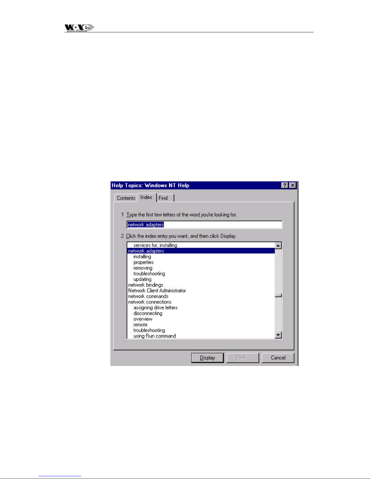
SPEEDCOM SC5800 User Manual
9 APPENDIX A: ELEMENT MANAGER PORT POINT-TO-
POINT SERIAL COMMUNICATIONS SETUP
This appendix summarizes how to set up a network connection (using PPP) between a computer
and the SC5800 Indoor Unit’s Element Manager port. It lists how the connection can be setup
and configured to allow data transfer and SNMP-based control of the SC5800 Indoor Unit.
Note: For both NT and Win 95 or 98 machines, check that a Network Adapter is installed.
The following screen capture shows the Windows help available to assist setting up
a serial comms network adapter. This screen appears when the Help function is
activated.
67
Page 70
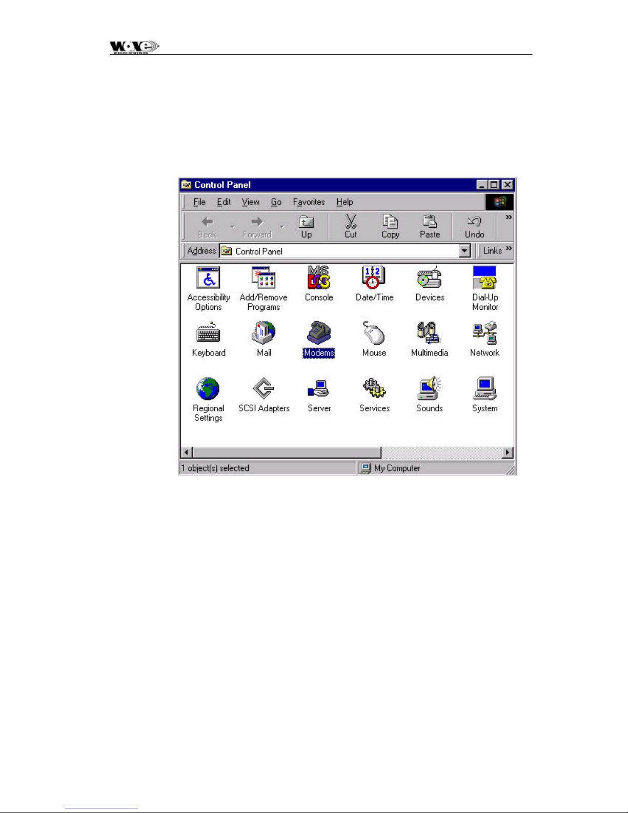
SPEEDCOM SC5800 User Manual
9.1 Adding a Modem: Windows NT
1. When working with a PC running a Windows NT, add a modem using the following
screen as a guideline. Click the Modems icon.
2. Verify your modem, or click Add to include another modem.
68
Page 71
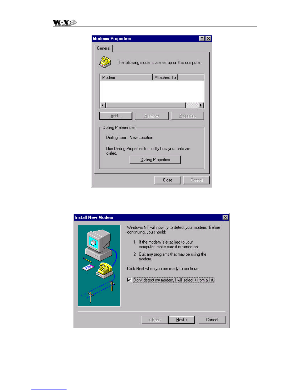
SPEEDCOM SC5800 User Manual
3. Follow the directions in the screen capture below and click Next.
4. Locate the manufacturer and model of your modem and click Next.
69
Page 72
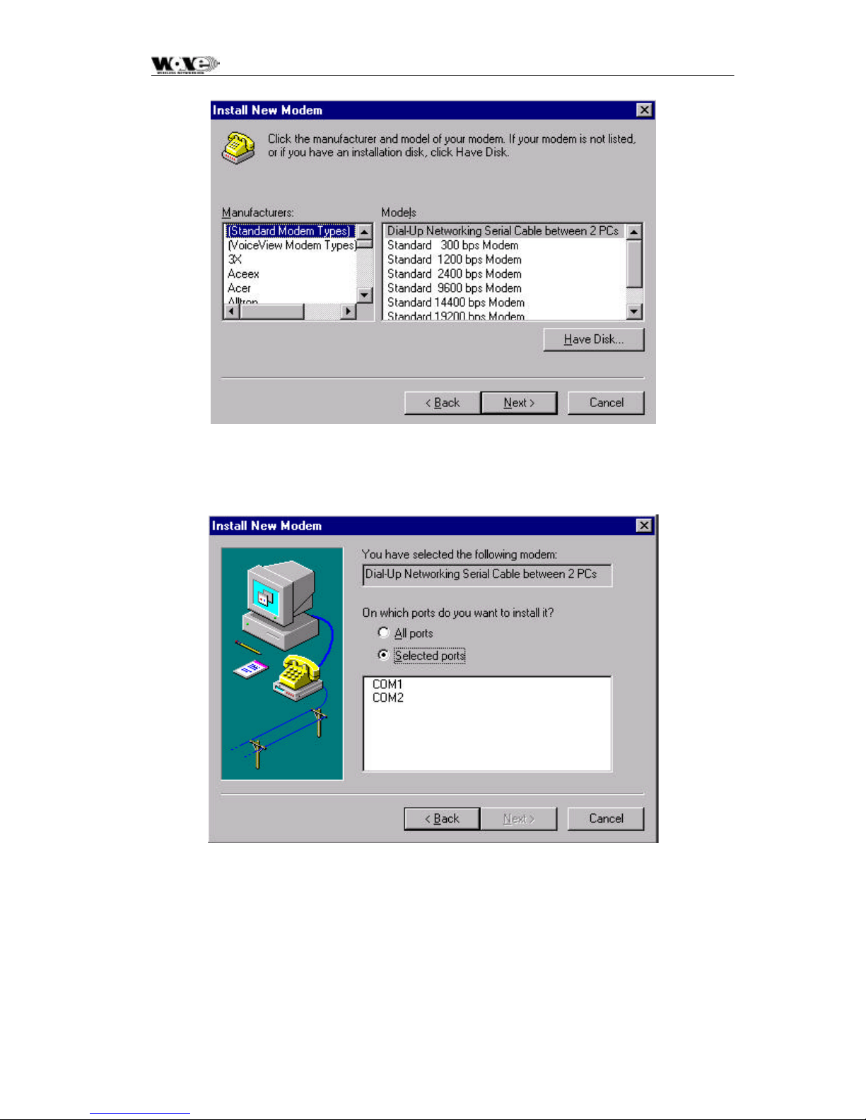
SPEEDCOM SC5800 User Manual
5. Windows verifies the modem selected. Select the option on which you want to install
the port (i.e., Selected ports option).
When the COM port has been selected, click Next. When completed, click Finish.
70
Page 73
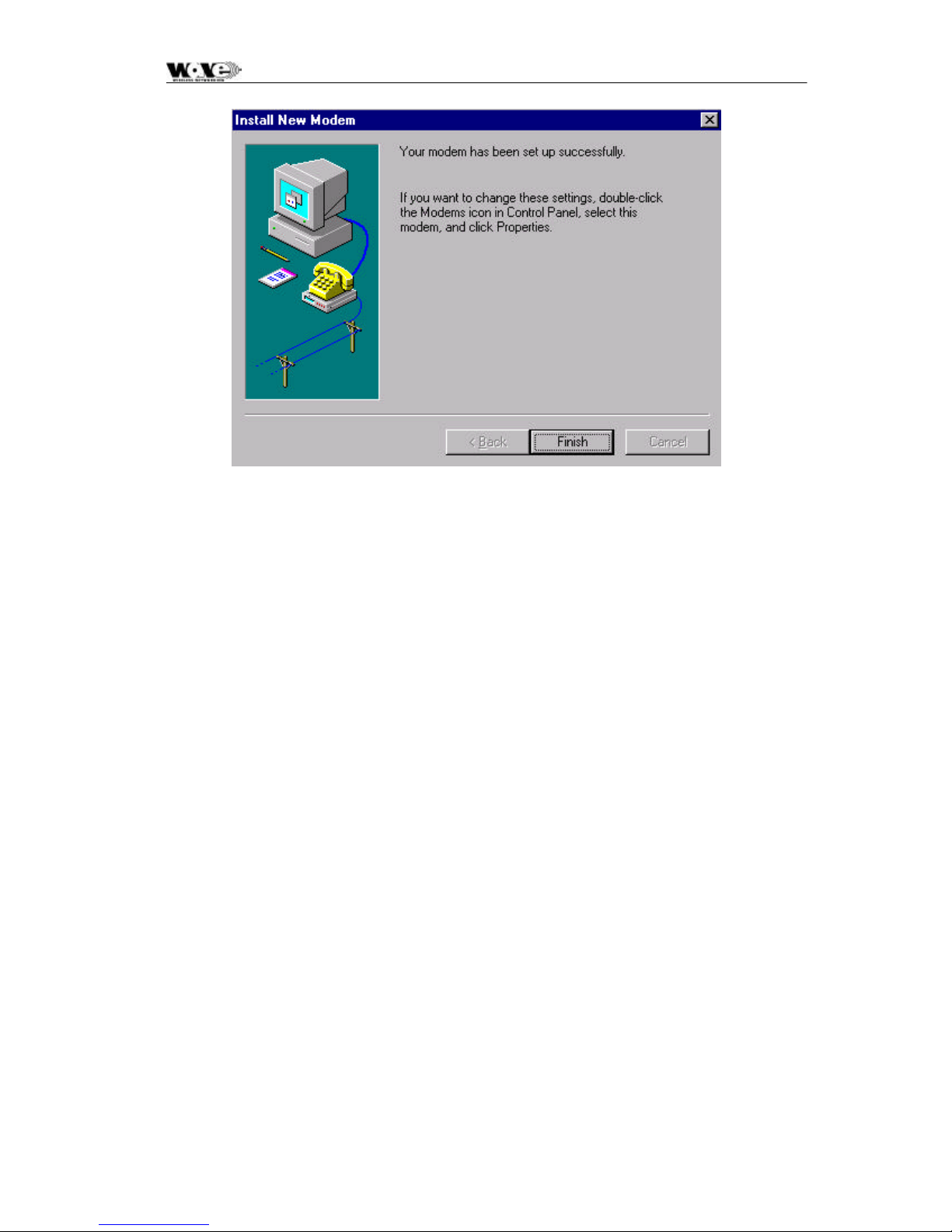
SPEEDCOM SC5800 User Manual
71
Page 74
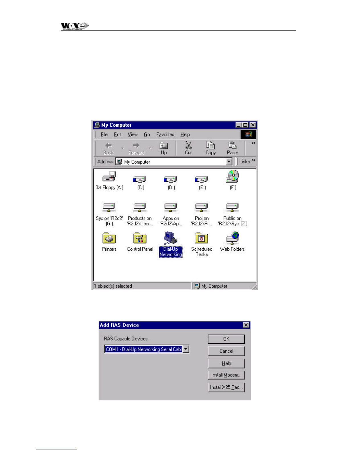
SPEEDCOM SC5800 User Manual
9.2 Adding Dial-up Networking: Windows NT
9.2.1 To add dial-up networking
1. From the desktop, double-click the My Computer icon. The following screen will be
displayed. Next, double-click the Dial-up Networking icon (as displayed in the screen
capture below).
2. The following windows are displayed:
72
Page 75
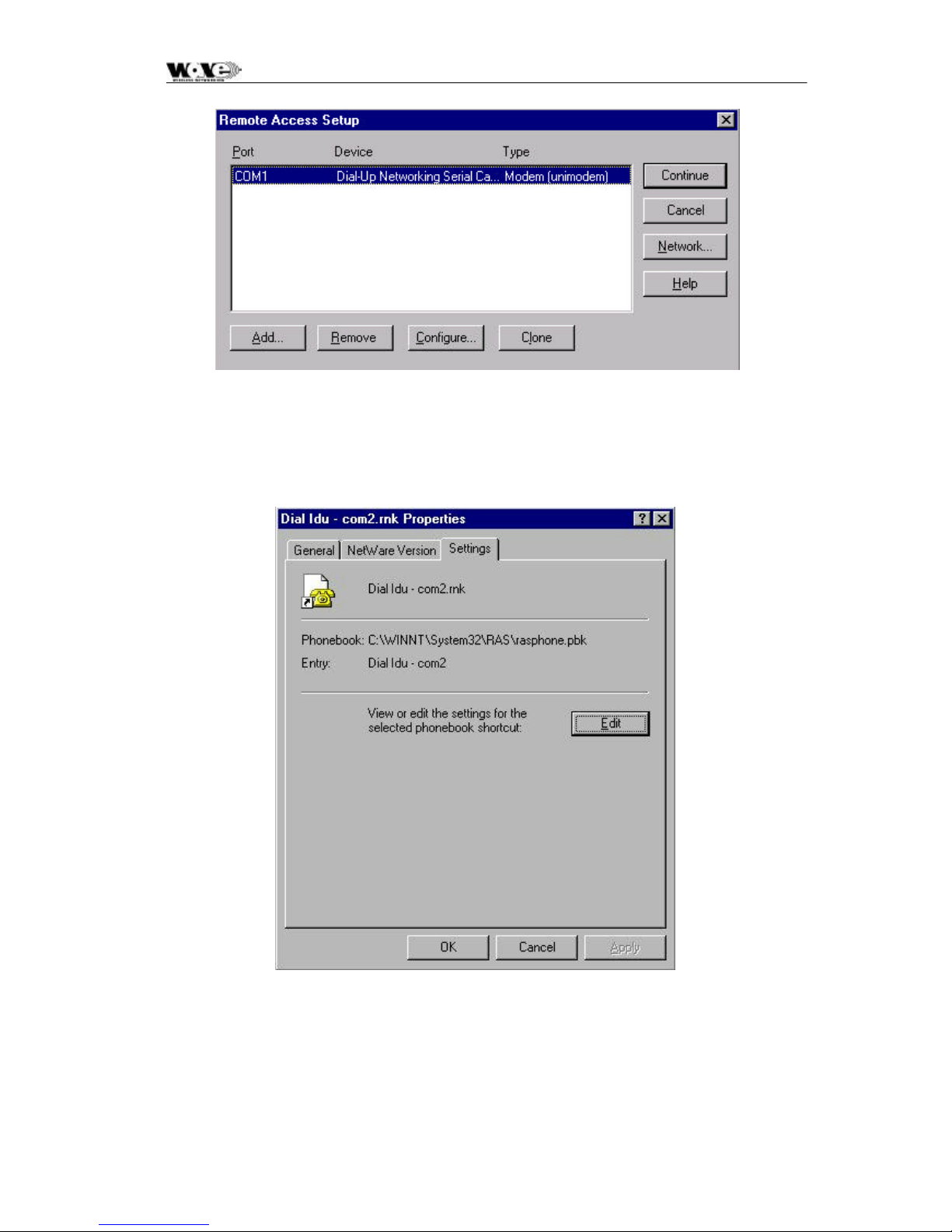
SPEEDCOM SC5800 User Manual
3. Whether COM1 or COM2 is selected from the RAS Capable Devices drop-down list
(see previous screen, setup the connection using the following screens as a guideline.
This allows establishment of a PPP connection between the computer and the SC5800
Indoor Unit’s Element Manager port.
73
Page 76
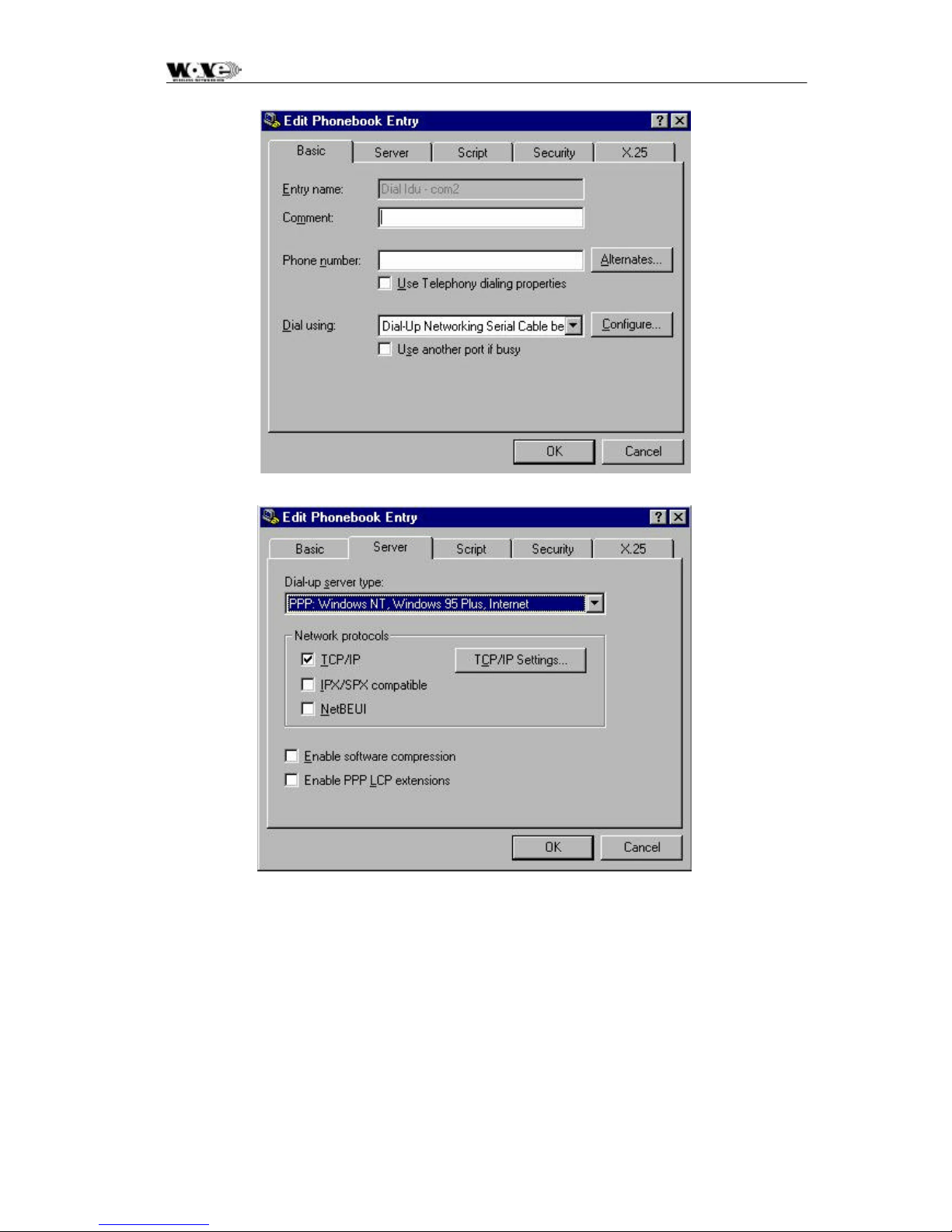
SPEEDCOM SC5800 User Manual
74
Page 77
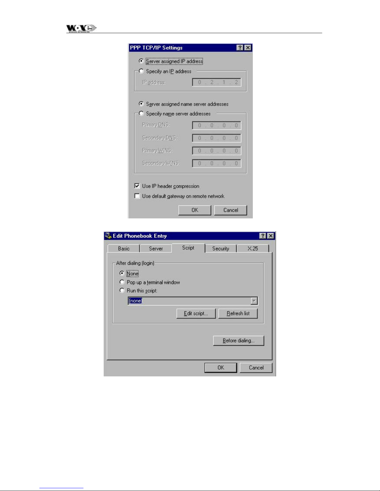
SPEEDCOM SC5800 User Manual
75
Page 78
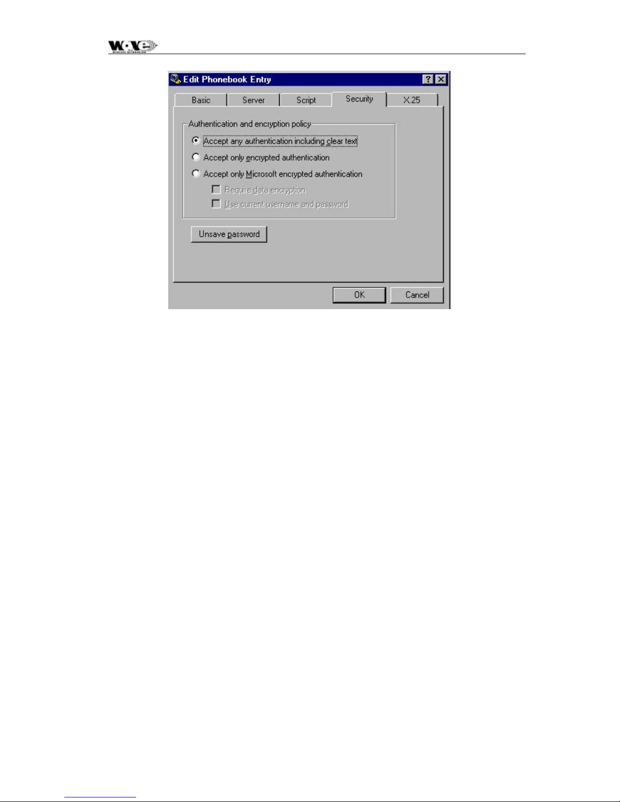
SPEEDCOM SC5800 User Manual
76
Page 79
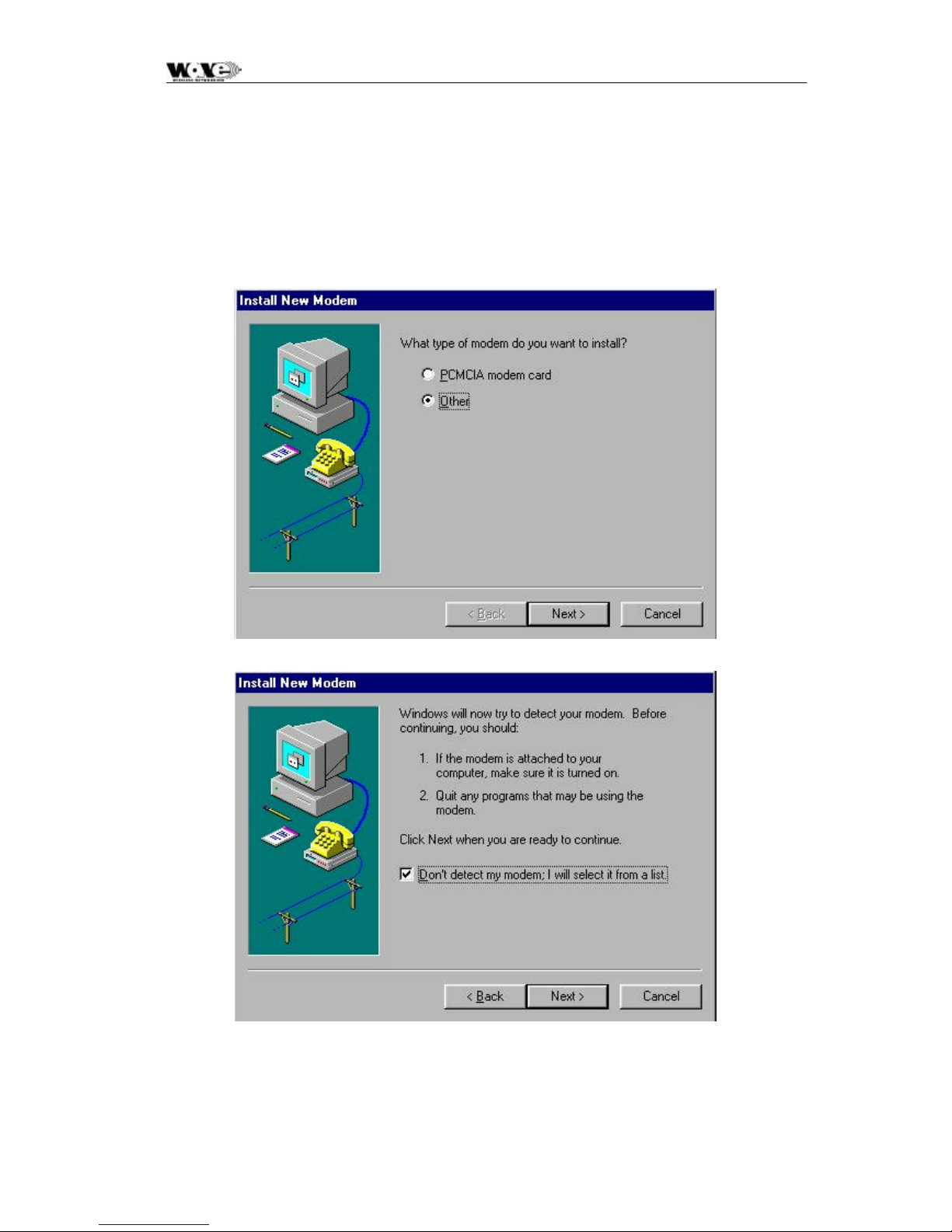
SPEEDCOM SC5800 User Manual
9. 3 Adding a Modem: Windows 95/98
1. When working with a PC running a Windows 95/98, add a modem using the following
screens as a guide.
2. Use the mdmnull.inf to add a serial cable modem connection capability to the PC or
laptop.
77
Page 80
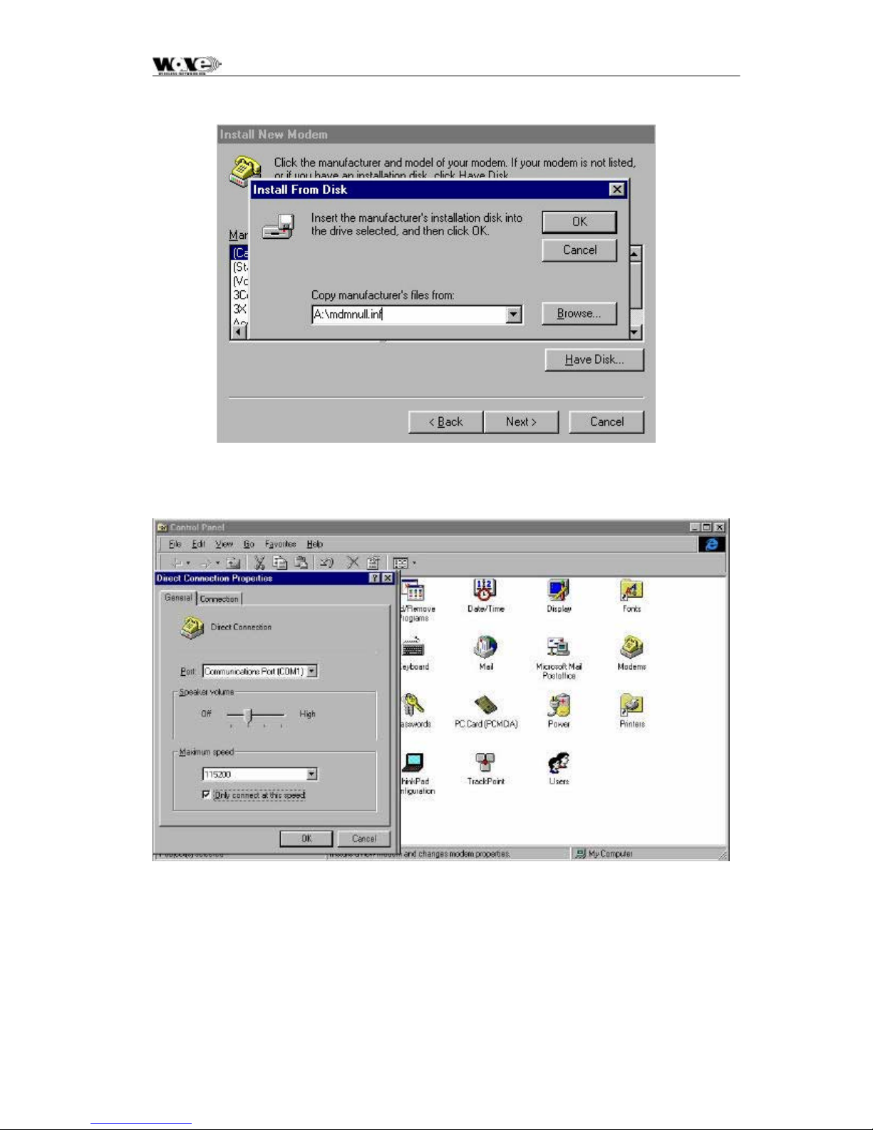
SPEEDCOM SC5800 User Manual
3. Once setup, use the following screens to set up the COM port’s parameters.
78
Page 81
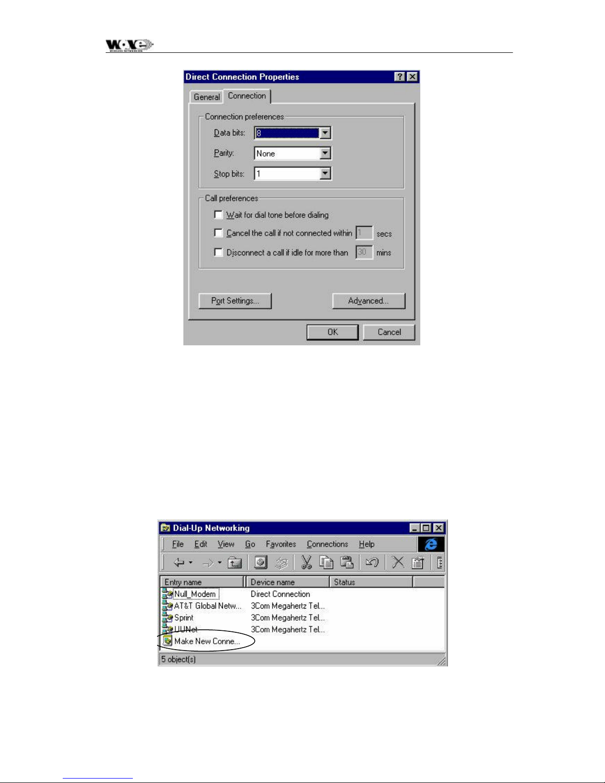
SPEEDCOM SC5800 User Manual
9.4 Adding Dial-up Networking: Windows 95/98
1. After adding the modem, set up the connection properties using the following screens as
a guide. This will allow establishment of a PPP connect ion between the computer and
the SC5800 Indoor Unit’s Element Manager port. A Null_Modem connection option as
shown below will be created. If one doesn’t exist, double-click the Make New
Connection icon (as circled below).
79
Page 82
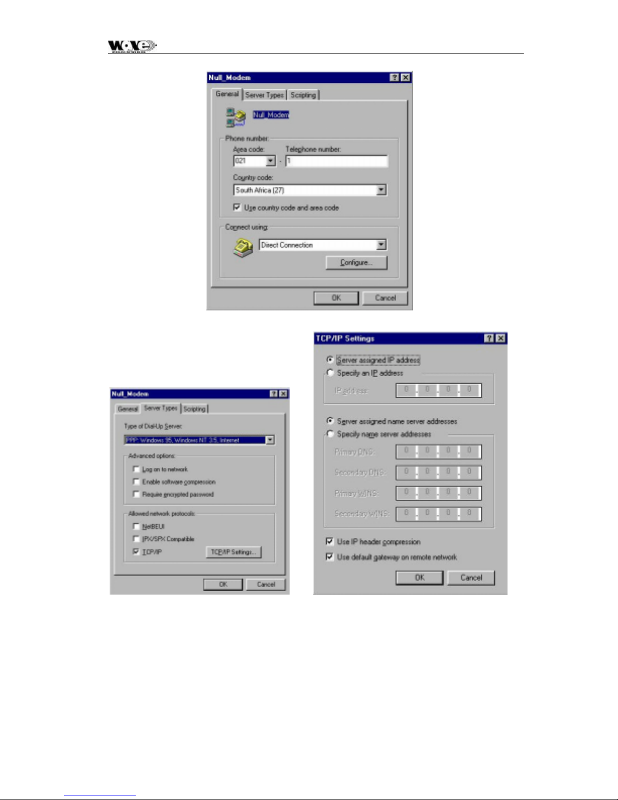
SPEEDCOM SC5800 User Manual
80
Page 83

SPEEDCOM SC5800 User
Manual
10 APPENDIX B: MANAGEMENT OF THE SC5800
All management of the SC5800 product is implemented using SNMP (Simple Network
Management Protocol), an open standard. The SC5800 product can be managed by:
1. Standard SNMP managers such as HP OpenView or SNMPc (i.e., there is Open Network
Management compatibility).
2. For rapid product installation, the NMS GUI Application (hereafter referred to as the NMSGA) provides extensive management functions on site and, via the microwave radio link,
can be used to access the SC5800 station on the opposite side of the link. The SC5800
NMS -GA is a software application that runs on a PC workstation such as a laptop or
notebook computer that is connected to an SC5800 Indoor Unit (IU) serial port (DB9 DTE)
or an Ethernet connection (10BaseT DTE) (both accessed via the IU front -panel).
10.1 SNMP and the SC5800
Use of SNMP within the product allows remote: configuration, monitoring of performance,
notification of alarms and firmware upgrades via an IP-network. Within an IP network supporting
routing of IP data, the radios can be supported from any remote location. The product can be
accessed via the Internet if the necessary gateways are provided. A GSM/PCS modem dial-up
capability provides another remote management option.
The SPEEDCOM (SC) Indoor Units have built-in SNMP agents and an extensive MIB
(Management Information Base). The SC5800 product uses SNMP V1 (RFC1155, 1157). The
user has access to an Enterprise MIB (obtainable though customer services) and MIB II (RFC
1213).
Access to the MIB via the IU SNMP agent is via Ethernet (10BaseT interface on the product's
front panel) or PPP (RFC 1661) via the product's serial channel Element Manager port. The use
of SNMP provides flexibility for operators with central equipment monitoring. It provides
management access to radio configuration (all data interfaces), interface status and statistics,
fault and maintenance information.
SNMP security (if enabled) is ensured by using a login and password to give th e user
administrator or basic user rights (a standard user rights option limits the ability to SET MIB
variables).
The product has threshold-based alarm generation (there is an extensive SNMP trap list with a
trap filter that is adjustable via SNMP). Network access (wired or wireless (i.e., GSM/PCS
Modem) allows over-the-air remote firmware uploading (FTP) with a load verification (and reversion)
capability.
81
Page 84

SPEEDCOM SC5800 User
Manual
There are three principle requirements to use SNMP with the SC5800 Radio Stations.
1. A Management Station that runs a SNMP Management Software package that is
installed on a networked or stand-alone PC that can be connected to an Indoor Unit either
using a serial connection or an Ethernet connection. From the Management station, the
agents within the SC5800 Indoor Units can be configured or polled for information.
2. Agent: The agent accepts SNMP GET, SET or GET-NEXT commands from the
Management Application software and collects or adjusts information from the Indoor
Unit's MIB.
3. Management Information Base (MIB): the MIB is a database that is accessed based on
the OID (object ID) the SNMP Manager has chosen. The SPEEDCOM (SC) Indoor Unit
used an Enterprise MIB and a standard MIB (MIB II) to store or allow access to
information relevant to the SPEEDCOM (SC) Link.
82
Page 85
SC5800 User Manual
10.2 The MIB Elements – OID (Object ID) DESCRIPTIONS
Object ID Group Object Type Access Description
1 Iso
1.3 Org
1.3.6 dod
1.3.6.1 internet
1.3.6.1.4 private
1.3.6.1.4.1 enterprises
1.3.6.1.4.1.1316 Wave Wireless
1.3.6.1.4.1.1316.1 products
1.3.6.1.4.1.1316.1.1 digitalradio
1.3.6.1.4.1.1316.1.1.1 mdrmte
1.3.6.1.4.1.1316.1.1.1.1 mdrmtePerformance
1.3.6.1.4.1.1316.1.1.1.1.1 mdrmtePayloadPerf
1.3.6.1.4.1.1316.1.1.1.1.1.1 mdrmtePpTable SEQUENCE
1.3.6.1.4.1.1316.1.1.1.1.1.1.1 mdrmtePpEntry SYNTAX
1.3.6.1.4.1.1316.1.1.1.1.1.1.1.1 mdrmtePpIndex INTEGER
1.3.6.1.4.1.1316.1.1.1.1.1.1.1.2 MdrmtePpLOS INTEGER read-only A Loss of Signal has been
1.3.6.1.4.1.1316.1.1.1.1.1.1.1.3 MdrmtePpAIS INTEGER read-only An Alarm Indication Signal has
1.3.6.1.4.1.1316.1.1.1.1.1. 2
1.3.6.1.4.1.1316.1.1.1.1.1.3
1.3.6.1.4.1.1316.1.1.1.1.1.4
1.3.6.1.4.1.1316.1.1.1.1.1.5 MdrmteCrcEbit† INTEGER read-only "Reflects the status of the 'E'
1.3.6.1.4.1.1316.1.1.1.1.2 mdrmteRFLinkPerf
1.3.6.1.4.1.1316.1.1.1.1.2.1 mdrmteCarrierDetect INTEGER read-only Indicates if a RF Carrier has
mdrmteCrcErrors† INTEGER read-only "The number of CRC4 or CRC6
mdrmteCrcTribSelect† INTEGER Rd-Write "The tributary selected for CRC
mdrmteCrcLock† INTEGER read- only "Indication of whether the CRC
detected on the input to a
tributary - there are four, one
for each tributary.
been detected on the input to a
tributary - there are four, one
for each tributary.
errors seen on the selected
tributary since the last time
errors were cleared."
checking."
checking algorithm has locked
onto a CRC frame signature in
the payload data."
bits in the frame."
been detected by Outdoor Unit
– if so, the header in the RF
Packet has been identified as a
potential valid packet - note
however, that it could be
received from another
transmitter that uses the same
83
Page 86

SC5800 User Manual
Object ID Group Object Type Access Description
1.3.6.1.4.1.1316.1.1.1.1.2.2 MdrmteRSSI †2 Gauge read-only A dBm value representative of
1.3.6.1.4.1.1316.1.1.1.1.2.3 mdrmteCurrentPER DisplayString read-only This is the current Packet Error
1.3.6.1.4.1.1316.1.1.1.1.2. 4 mdrmteMaximizedPER DisplayString read-only This is the maximum Packet
1.3.6.1.4. 1.1316.1.1.1.1.2.5 mdrmteLinkUnavailable INTEGER read-only Based on G.826 criteria, this
1.3.6.1.4.1.1316.1.1.1.1.2.6 mdrmteFrameUnlock INTEGER read-only The data that is transmitted
1.3.6.1.4.1.1316.1.1.1.1.2.7
1.3.6.1.4.1.1316.1.1.1.1.2.8 MdrmteErrSecRatioExceeded INTEGER read-only The ESR is a ratio of the
1.3.6.1.4.1.1316.1.1.1.1.2.9 mdrmteSevErrSecRatioExceeded INTEGER read-only The SESR is a ratio of the
mdrmteRemoteFrameUnlock†
INTEGER read-only Frame-lock
header format.
the received signal level. The
value detected is representative
of the level that would be
measured should a CW signal
be input at the Outdoor Unit's
Diplexer RF Port - a Spread
Spectrum signal will appear to
be 20 dB lower. The NMS
makes an adjustment for this
by using a 20 dB offset
(addition to the Indoor Unit MIBindicated value).
Rate and is based on the
number of uncorrectable
packets/blocks being detected
by the FEC (Forward Error
Correction) circuitry within the
Indoor Unit (based on the
number of errored packets
divided by the total number of
packets transmitted in a
measurement period of
250msec).
Error Rate detected during the
last measurement period, based
number of maximum number of
uncorrectable packets/blocks
detected by the FEC circuitry
within the Indoor Unit.
MIB element indicates RF Link
Availability/Non-availability.
across the RF Link is conveyed
in a frame, compiled within the
Indoor Unit's FPGA. The
received data frame is
examined to see that the frame,
with a suitable format has been
received.
(mdrmteFrameUnlock) as seen
by the other end of the link is
fed back here.
number of Errored seconds (one
second periods within which
uncorrectabl e packets were
counted by the FEC IC) to the
total time in seconds.
number of Severely Errored
seconds (one second periods
within which 30% of packets
ove r the RF Link had
uncorrectable errors) to the total
time in seconds.
2
† indicates Version 2.00 MIB additions/name changes
84
Page 87

SC5800 User Manual
Object ID Group Object Type Access Description
1.3.6.1.4.1.1316.1.1.1.1.2.10 mdrmteBkgrndBlkErrRatioExceeded INTEGER read-only The BBER is a ratio of the
1.3.6.1.4.1.1316.1.1.1.1.2.11 MdrmteMinorPERExceeded INTEGER read-only This parameter indicates if the
1.3.6.1.4.1.1316.1.1.1.1.2.12 mdrmteMajorPERExceeded INTEGER read-only This parameter indicates if the
1.3.6.1.4.1.1316.1.1.1.1.2.13 mdrmteCriticalPERExceeded INTEGER read-only This parameter indicates if the
1.3.6.1.4.1.1316.1.1.1.1.2.14 mdrmtePrevParamsRestored INTEGER read-only Indicates if “auto recovery” for
1.3.6.1.4.1.1316.1.1.1.1.2.15 Deprecated1 INTEGER write-only Deprecated
1.3.6.1.4.1.1316.1.1.1.1.3 mdrmteG826
1.3.6.1.4.1.1316.1.1.1.1.3.1 mdrmteStatus INTEGER read-only Indicates if 'G.826-like' errored,
1.3.6.1.4.1.1316.1.1.1.1.3.2 mdrmteTotalSeconds Counter read-only Indicates the total number of
1.3.6.1.4.1.1316.1.1.1.1.3.3 mdrmteAvailableSeconds Counter read-only A period of unavailable time
number of uncorrectable
blocks/packets received to the
total number of packets
received.
minor packet (uncorrectable by
FEC) error rate has been
exceeded based on the defined
threshold listed in the
mdrmteFAULT mdrmtePerfTrapThreshold
group. A GH filter is applied to
the calculation. This GH filter
functions as a weighted average
where the GH Average Filter
Fraction is the proportion of the
instantaneous PER used in the
current seconds calculation.
The remainder (1-Fraction(0.7))
is taken from the previous 250
milli-second calculation.
major packet (uncorrectable by
FEC) error rate has been
exceeded based on the defined
threshold listed in the
mdrmteFAULT mdrmtePerfTrapThreshold
group.
critical packet (uncorrectable by
FEC) error rate has been
exceeded based on the defined
threshold listed in the
mdrmteFAULT mdrmtePerfTrapThreshold
group.
the Outdoor Unit settings had to
be invoked due to an unsuitable
choice of frequency or power
settings for the RF link.
severely errored and
unavailable conditions have
been monitored on the RF Link.
seconds, both available and
unavailable.
begins at the onset of ten
consecutive SES events.
These ten seconds are
considered to be part of
unavailable time. A new period
of available time begins at the
onset of ten consecutive nonSES ev ents. These ten
seconds are considered to be
part of available time.
85
Page 88
SC5800 User Manual
Object ID Group Object Type Access Description
1.3.6.1.4.1.1316.1.1.1.1.3.4 mdrmteUnavailableSeconds Counter read-only A period of unavailable time
1.3.6.1.4.1.1316.1.1.1.1.3.5 mdrmteErroredSeconds Counter read-only A one second period with one or
1.3.6.1.4.1.1316.1.1.1.1.3.6 mdrmteSeverelyErroredSeconds Counter read-only A one-second period which
1.3.6.1.4.1.1316.1.1.1.1.3.7 mdrmteErroredBlocks Counter read-only A packet that has been
1.3.6.1.4.1.1316.1.1.1.1.3.8 mdrmteBackgroundBlockErrors Counter read-only An errored block not occurring
1.3.6.1.4.1.1316.1.1.1.1.3.9
1.3.6.1.4.1.1316.1.1.1.1.3.10 mdrmteSeverelyErroredSecondsRatio DisplayString read-only The ratio of SES to total
1.3.6.1.4.1.1316.1.1.1.1.3.11 mdrmteBackgroundBlockErrorRatio DisplayString read-only The ratio of Background Block
1.3.6.1.4.1.1316.1.1.1.1.3.12 Deprecated2 INTEGER write-only Deprecated
1.3.6.1.4.1.1316.1.1.1.1.3.13 mdrmteCorrectedSymbols INTEGER read-only This parameter lists the number
1.3.6.1.4.1.1316.1.1.1.1.4 Counters†
1.3.6.1.4.1.1316.1.1.1.1.4.1
1.3.6.1.4.1.1316.1.1.1.1.4.2 MdrmteLostLinkRxPkts† COUNTER read-only Indicates the total number of
1.3.6.1.4.1.1316. 1.1.1.1.4.3 MdrmteLostWaySideTxPkts † COUNTER read-only Indicates the total number of
1.3.6.1.4.1.1316.1.1.1.1.4.4 mdrmteEtherRetries † COUNTER read-only Indicates the total number of
1.3.6.1.4.1.1316.1.1.1.1.4.5
mdrmteErroredSecondsRatio DisplayString read-only The ratio of ES to total seconds
mdrmteLostEthRxPkts† COUNTER read-only Indicates the total number of
mdrmteScc1FullCnt † COUNTER read-only Indicates the total number of
begins at the onset of ten
consecutive SES events.
These ten seconds are
considered to be part of
unavailable time. A new period
of available time begins at the
onset of ten consecutive nonSES events. These ten
seconds are considered to be
part of available time.
more errored packets
(uncorrectable packets) or at
least one defect.
contains > 30% errored blocks
or at least one defect. SES is a
subset of ES.
identified as containing
uncorrectable bits by the FEC
circuitry.
as part of a SES.
in available time during a fixed
measurement interval.
seconds in available time during
a fixed measurement interval.
Errors (BBE) to total blocks in
the available time during a fixed
measurement interval. The
count of total blocks excludes
all blocks during SESs.
of corrected symbols i.e. those
corrected by the FEC.
times an ethernet packet could
not be buffered
times a link packet could not be
buffered
times a wayside packet could
not be buffered
(collisions) packets that were
retransmitted on Ethernet
times SCC1 was full to capacity
86
Page 89
SC5800 User Manual
Object ID Group Object Type Access Description
1.3.6.1.4.1.1316.1.1.1.1.4.6
1.3.6.1.4.1.1316.1.1.1.1.4.7 mdrmteScc1UnderrunCnt† COUNTER read-only Indicates the total number of
1.3.6.1.4.1.1316.1.1.1.1.4.8
1.3.6.1.4.1.1316.1.1.1.1.4.9
1.3.6.1.4.1.1316.1.1.1.1.4.10 mdrmteScc2RxBdNonOctCnt† COUNTER read-only Indicates the total number of
1.3.6.1.4.1.1316.1.1.1.1.4.11 mdrmteScc2RxBdCrcCnt† COUNTER read-only Indicates the total number of
1.3.6.1.4.1. 1316.1.1.1.1.5 mdrmteResetAllPerfData INTEGER write-only Reset all parameters associated
1.3.6.1.4.1.1316.1.1.1.2 mdrmteConfiguration
1.3.6.1.4.1.1316.1.1.1.2.1 MdrmtePayloadConf
1.3.6.1. 4.1.1316.1.1.1.2.1.1 MdrmteDataRate INTEGER read-write Configure the tributary data
1.3.6.1.4.1.1316.1.1.1.2.1.2 mdrmteLineCodeType INTEGER read-write Defines the line code types for
1.3.6.1.4.1.1316.1.1.1.2.1.3 mdrmtePcTable SEQUENCE
1.3.6.1.4.1.1316.1.1.1.2.1.3.1 mdrmtePcEntry SYNTAX
1.3.6.1.4.1.1316.1.1.1.2.1.3.1.1 mdrmtePcIndex INTEGER
mdrmteScc2FullCnt † COUNTER read-only Indicates the total number of
times SCC2 was full to capacity
times SCC1 ran out of BDs
mdrmteScc2UnderrunCnt † C OUNTER read- only Indicates the total number of
times SCC2 ran out of BDs
mdrmteScc2RxBdAbortCnt † COUNTER read-only Indicates the total number of
times SCC2 received an
aborted frame
times SCC2 received a Non
octet aligned frame
times SCC2 received
with Packet Error and G.826
measurements for the RF Link.
interface rate - either E1 or T1.
the tributaries, either HDB3 or
AMI for E1 tributaries or B8ZS
or AMI for T1 tributaries.
1.3.6.1.4.1.1316.1.1.1.2.1.3.1.2 mdrmtePcLabel DisplayString read-write E1/T1 Payload configuration
1.3.6.1.4.1.1316.1.1.1.2.1.3.1.3 mdrmtePcActive INTEGER read-write Defines whether tributaries are
1.3.6.1.4.1.1316.1.1.1.2.2 mdrmteRFLinkConf
1.3.6.1.4.1.1316.1.1.1.2.2.1 mdrmteTxPower INTEGER read-write Allows setup of the output power
1.3.6.1.4.1.1316.1.1.1.2.2.2 mdrmteBandPlan INTEGER read-write The SC5800 Outdoor Units
1.3.6.1.4.1.1316.1.1.1.2.2.3 mdrmteTxFrequencyPlanD INTEGER read-write Frequency plan D allows
tributary label.
active or inactive.
available at the diplexer port of
the Outdoor Unit.
operate in the 5.725 GHz to
5.850 GHz ISM frequency band.
The SC5800 has predefined
frequency channel plans
(termed A, B, C and D). Refer
to the User's manual for details
on defined frequencies.
independent control of transmit
and receive frequencies. This
enables a very flexible
frequency plan and can be used
to overcome interference in the
5.8 GHz ISM band. The
frequencies that can be used in
the lower or upper sub-bands
can be selected in 1 MHz
increments. Performance
87
Page 90

SC5800 User Manual
Object ID Group Object Type Access Description
1.3.6.1.4.1.1316.1.1.1.2.2.4 mdrmteRxFrequencyPlanD INTEGER read-write Refer to the
1.3.6.1.4.1.1316.1.1.1.2.2.5 mdrmteTransmitBand INTEGER read-only This value is read from the
1.3.6.1.4.1.1316.1.1.1.2.2.6 MdrmteReserved2 INTEGER
1.3.6.1.4.1.1316.1.1.1.2.2.7 mdrmteRegulations INTEGER This parameter is read from the
1.3.6.1.4.1.1316.1.1.1.2.2.8 mdrmteAutoRecovery INTEGER read-only This feature is used if the user
1.3.6.1.4.1.1316.1.1.1.2.2.9 mdrmteOURateOverride INTEGER read-write Deprecated
1.3.6.1.4.1.1316.1.1.1.2.2.10 mdrmteOUDataRate INTEGER read-write A settable rate that allows a
1.3.6.1.4.1.1316.1.1.1.2.2.11 mdrmteTxFrequencyCurrent INTEGER read-only This value [MHz] is read back
1.3.6.1.4.1.1316.1.1.1.2.2.12 mdrmteRxFrequencyCurrent INTEGER read-only This value [MHz] is read back
degradation can be expected
when operating using channel
plan D mode and the chosen
frequencies are close to the
sub-band edges i.e. a choice of
one of the high frequencies in
the lower sub-band and one of
the lower frequencies in the
upper sub-band. The allocation
of Channel plan D frequencies
is Lower Sub-band - 5735-5771
MHz, Upper Sub-band - 58045840 MHz. The user must take
note of whether the radio is a
high or low band unit before
choosing a set of transmit and
receive frequencies. Note also
that THE TX AND RX
FREQUENCIES MUST BE
SELECTED BEFORE BAND
PLAN D OPTION IS SELECTED
VIA THE MIB.
mdrmteTxFrequencyPlanD
description.
Outdoor Unit via the Indoor Unit
and defines whether it transmits
in the Lower Sub-band - 57355771 MHz or Upper Sub-band 5804-5840 MHz.
Outdoor Unit via the Indoor Unit
and defines regulatory
compliance of the Outdoor Unit.
is installing a link from one side
and there is no assistance on
the opposite side of the link. It
mitigates against the link failing
and not being able to be reestablished. If “auto recovery”
is enabled, the required
operational RF parameters are
programmed into the Outdoor
Units by the local and remote
Indoor Units. If communication
between the two Indoor Units
has not reactivated within 5
seconds, the previous (working)
'default' RF parameters are
programmed into the respective
Outdoor Units.
reduced transfer data rate over
the RF Link.
from the Outdoor Unit and
defines the transmit frequency
of the Outdoor Unit.
from the Outdoor Unit and
88
Page 91

SC5800 User Manual
Object ID Group Object Type Access Description
1.3.6.1.4.1.1316.1.1.1.2.2.13 mdrmteNonAutoBandPlan INTEGER read-write Same as mdrMTEBandPlan
1.3.6.1.4.1.1316.1.1.1.2.2.14 mdrmteNonAutoTxFreqPlanD INTEGER read-write Same as mdrTxFrequencyPlanD
1.3.6.1.4.1.1316.1.1.1.2.2.15 mdrmteNonAutoRxFreqPlanD INTEGER read-write Same as mdrTxFrequencyPlanD
1.3.6.1.4.1.1316.1.1.1.2.2.16 mdrmteNonAutoTxPower INTEGER read-write Same as mdrTxPower setting in
1.3.6.1.4.1.1316.1.1.1.2.3 mdrmteServiceChannel
1.3.6.1.4.1.1316.1.1.1.2.3.1 mdrmteScDataRate†3 INTEGER read-write Bit rate used across the
1.3.6.1.4.1.1316.1.1.1.2.3.2 mdrmteScDataBits†4 INTEGER read-write The data width - can be 7 or 8
1.3.6.1.4.1.1316.1.1.1.2.3.3 MdrmteScParity INTEGER read-write Serial channel - set to none, odd
1.3.6.1.4.1.1316.1.1.1.2.3.4 MdrmteScStopBits INTEGER read-write The number of stop bits can be
1.3.6.1.4.1.1316.1.1.1.2.3.5 mdrmteScFlowControl INTEGER read-write Either hardware or no f low
1.3.6.1.4.1.1316.1.1.1.2.3.6 mdrmteScStatusDump INTEGER read-write Allows the wayside service
1.3.6.1.4.1.1316.1.1.1.2.4 MdrmteGeneral
1.3.6.1.4.1.1316.1.1.1.2.4.1 MdrmteStationName DisplayString read-write The station name is stored in
defines the receive frequency
of the Outdoor Unit.
setting in this MIB group except
“auto recovery” is not enabled this allows control of the
Outdoor Unit frequencies
without the “auto recovery”
feature attempting to intervene
and re-establish setup of an
operational RF Link.
setting in this MIB group except
“auto recovery” is not enabled this allows control of the
Outdoor Unit Plan D frequencies
without the “auto recovery”
feature attempting to intervene
and re-establish setup of an
operational RF Link.
setting in this MIB group except
“auto recovery” is not enabled this allows control of the
Outdoor Unit Plan D frequencies
without the “auto recovery”
feature attempting to intervene
and re-establish setup of an
operational RF Link.
this MIB group except “auto
recovery” is not enabled - this
allows control of the Outdoor
Unit power level setting without
the “auto recovery” feature
attempting to intervene and reestablish setup of an operational
RF Link.
wayside service channel link.
bits.
or even.
set to 1 or 2.
control is used.
(serial) channel to be used as a
diagnostics port [deprecated].
the Indoor Unit in non-volatile
3
Fixed at 115.2kbps in Version 1.00 and 2.00, 2.01, 2.02 IU firmware releases.
4
Serial setting – 8 bits, no parity, 1 stop bit
89
Page 92

SC5800 User Manual
Object ID Group Object Type Access Description
1.3.6.1.4.1.1316.1.1.1.2.4.2 mdrmteIUSerialNumber DisplayString read-only An electronic serial number is
1.3.6.1.4.1.1316.1.1.1.2.4.3 mdrmteIUFirmwareVersion DisplayString read-only The Indoor Unit firmware
1.3.6.1.4.1.1316.1.1.1.2.4.4 mdrmteIUBootkernelVersion DisplayString read-only The Indoor Unit bootkernel
1.3.6.1.4.1.1316.1.1.1.2.4.5 mdrmteOUSerialNumber INTEGER read-only The Outdoor Serial Number is
1.3.6.1.4.1.1316.1.1.1.2.4.6 MdrmteOUPICFirmwareVersion DisplayString read-only The Outdoor Unit PIC firmware
1.3.6.1.4.1.1316.1.1.1.2.4.7 mdrmteOUPayloadSupport INTEGER Deprecated.
1.3.6.1.4.1.1316.1.1.1.2.4.8 mdrmteDate DisplayString read-write This is a date record that is
1.3.6.1.4.1.1316.1.1.1.2.4.9 mdrmteTime DisplayString read-write This is a time record that is
1.3.6.1.4.1.1316.1.1.1.2.4.10 mdrmteNOVRAMInit INTEGER read-write If activated, the Nonvolatile
1.3.6.1.4.1.1316.1.1.1.2.4.11 mdrmteFECBypass INTEGER read-write This is primarily a laboratory
1.3.6.1.4.1.1316.1.1.1.2.4.12 mdrmteFECCorrectableSymbols INTEGER read-write This is primarily a laboratory
1.3.6.1.4.1.1316.1.1.1.2.4.13 mdrmteTribCode DisplayString read-write This is a text entry code (16
1.3.6.1.4.1.1316.1.1.1.2.4.14 mdrmteIndoorUnitBarCodeNumber† DisplayString read-write This is a text entry code used to
memory - limited to 14
characters in length.
read from the Indoor Unit - this
number is unique for each IU
and is derived from an IC that
is used within the product.
version is the version of
application firmware that loaded
into the product's application
Flash.
version is the version of boot
firmware that loaded into the
product's Boot Flash.
programmed into the OU at time
of manufacture and is read via
the Indoor Unit.
number is programmed into the
OU at time of manufacture and
is read via the Indoor Unit.
recovered from the Indoor
Unit's Real Time Clock.
recovered from the Indoor
Unit's Real Time Clock.
memory is initialised to a set of
default parameters.
test entry used to control
whether the FEC circuitry within
the Indoor Unit is activated. By
default the FEC is not
bypassed i.e. FEC is active.
test entry used to control the
FEC correction power - 20 parity
symbols are appended to the
transmit packet - 10 is the
maximum number of symbols
the FEC circuitry can correct.
At a maximum, 20 symbols in
error can be detected but only
10 can be corrected - the higher
the correction power selected,
the greater the improvement in
system gain.
characters) used to allow
activation of tributaries on the
Indoor Units. It is unique to the
Indoor Unit based on a
hardware-dependent serial
number in the IU.
90
Page 93

SC5800 User Manual
Object ID Group Object Type Access Description
1.3.6.1.4.1.1316.1.1.1.2.4.15
1.3.6.1.4.1.1316.1.1.1.2.5 mdrmteFirmware
1.3.6.1.4.1.1316.1.1.1.2.5.1 mdrmteFTPServerStatus† INTEGER read-write This allows
1.3.6.1.4.1.1316.1.1.1.2.5.2 mdrmteFlashNewFirmware† INTEGER read-write This entry determines the time
1.3.6.1.4.1.1316.1.1.1.3 mdrmteFault
1.3.6.1.4.1.1316.1.1.1.3.1 mdrmteInfo
1.3.6.1.4.1.1316.1.1.1.3.1.1 mdrmteLEDTable SEQUENCE A group of LEDs on the front
1.3.6.1.4.1.1316.1.1.1.3.1.1.1 mdrmteLEDEntry SYNTAX A LED entry containing objects
1.3.6.1.4.1.1316.1.1.1.3.1.1.1.1 mdrmteLED Index INTEGER A unique value for each LED in
1.3.6.1.4.1.1316.1.1.1.3.1.1.1.2 mdrmteLEDLabel DisplayString read-only SYSTEM Green OK, Orange
1.3.6.1.4.1.1316.1.1.1.3.1.1.1.3 mdrmteLEDState INTEGER read-only The current state of the LED -
1.3.6.1.4.1.1316.1.1.1.3.1.1.1.4 mdrmteLEDColour INTEGER read-only The current colour of the LED -
1.3.6.1.4.1.1316.1.1.1.3.1.2 mdrmteOutdoorUnitComms INTEGER read-only Describes the state of
mdrmteIndoorUnitPCBrevision† DisplayString read-write "This is a numeric entry code
allow storage of the Indoor
Unit's bar code serial number
(as seen on the outside of the
on the outside of product's
housing).
used to reflect the PCB revision
number and modification
status."
activation/deactivation of the
FTP server that runs in the
Indoor Unit and is used to
upload new revisions of
firmware via a routed IP
network.
when the new version of
firmware will be activated.
panel of the Indoor Unit.
describing a particular LED.
the Indoor Unit. Its value
ranges from 1 to the number of
LEDs on the front panel of the
Indoor Unit.
(OU/IU Comms Error), Red
(OU/IU Comms Down)
PAYLOAD Green OK, Orange
(AIS Detected), Red (LOS
Detected)RF LINK Green OK,
Orange (FEC Correcting Errors),
Red (FEC unable to correct
errors)In ALL cases flashing red
and orange LEDs imply historic
alarm conditions (The alarm can
be cleared using the front panel
button 'position 1': see next
paragraph).
for a detailed description of
functionality, see the
mdrmteLEDLabel entry.
for a detailed description of
functionality, see the
mdrmteLEDLabel entry.
communication with the Outdoor
unit in terms of whether it is up
or down completely.
Alternatively, if there were
errors, these are identified as
comms errors (based on a CRC
check) or content errors (i.e.
91
Page 94
SC5800 User Manual
Object ID Group Object Type Access Description
1.3.6.1.4.1.1316.1.1.1.3.1.3 mdrmteOutdoorUnitResetType INTEGER read-only This message is read from the
1.3.6.1.4.1.1316.1.1.1.3.1.4 mdrmteOutdoorUnitLockDetect INTEGER read-only The transmit RF synthesizer,
1.3.6.1.4.1.1316.1.1.1.3.2 mdrmteSelfTest
1.3.6.1.4.1.1316.1.1.1.3.2.1 mdrmteFlash INTEGER read-only Identifies pass/fail status of the
1.3.6.1.4.1.1316.1.1.1.3.2.2 mdrmteDRAM INTEGER read-only Identifies pass/fail status of the
1.3.6.1.4.1.1316.1.1.1.3.2.3 mdrmteSRAM INTEGER read-only Identifies pass/fail status of the
1.3.6.1.4.1.1316.1.1.1.3.2.4 mdrmteLineInterface INTEGER read-only Identifies pass/fail status of the
1.3.6.1.4.1.1316.1.1.1.3.2.5 mdrmteFPGA INTEGER read-only Identifies pass/fail status of the
1.3.6.1.4.1.1316.1.1.1.3.2.6 mdrmteFEC INTEGER read-only Identifies pass/fail status of the
1.3.6.1.4.1.1316.1.1.1.3.2.7 mdrmteRealTimeClock INTEGER read-only Identifies pass/fail status of the
1.3.6.1.4.1.1316.1.1.1.3.2.8 mdrmteIndoorUnitResetType INTEGER read-only This message is read from the
1.3.6.1.4.1.1316.1.1.1.3.2.9 mdrmteLoopbackMode INTEGER read-write Entry defines the loopback
1.3.6.1.4.1.1316.1.1.1.3.2.10 mdrmteLoopbackTimeOut INTEGER read-write This is the number of seconds
1.3.6.1.4.1.1316.1.1.1.3.3 mdrmteTrapManagement
1.3.6.1.4.1.1316.1.1.1.3.3.1 mdrmteTrapFilter INTEGER read-write Alarms within the MDR product
1.3.6.1.4.1.1316.1.1.1.3.3.2 mdrmteNumberTrapManagers INTEGER read-only This entry shows the number of
1.3.6.1.4.1.1316.1.1.1.3.3.3 mdrmteTrapManagerTable SEQUENCE
1.3.6.1.4.1.1316.1.1.1.3.3.3.1 mdrmteTrapManagerEntry SYNTAX
1.3.6.1.4.1.1316.1.1.1.3.3.3.1.1 mdrmteTrapManagerIndex INTEGER
undeclared, unused messages).
Outdoor Unit and identifies the
last reason for a reset within the
OU.
receive RF synthesizer and IF
phased locked loop lock detect
signals are monitored and
reported via this MIB element.
Indoor Unit's application flash.
Indoor Unit's Dynamic RAM.
Indoor Unit's Static RAM.
Indoor Unit's Line Interface IC.
Indoor Unit's FPGA interface
registers to the microprocessor.
Indoor Unit's FEC IC electrical
interface.
Indoor Unit's Real Time Clock.
Indoor Unit and identifies the
last reason for a reset wi thin the
IU.
mode of a radio station in terms
of loopback at either the
payload line interface level,
baseband processor level in an
OU or RF loopback in the OU.
the loopback will run for until it
times out.
are classified as critical, major,
minor or informational. The trap
filter allows screening of alarms
before they are dispatched as
traps.
trap managers allowed.
1.3.6.1.4.1.1316.1.1.1.3.3.3.1.2 mdrmteTrapManagerIP IpAddress read-write This is the IP address of the
92
management station that is set
up to detect and act upon
Page 95
SC5800 User Manual
Object ID Group Object Type Access Description
1.3.6.1.4.1.1316.1.1.1.3.3.3.1.3 mdrmteTrapManagerComm DisplayString read-write This is t he “ SNM P co mmun ity
1.3.6.1.4.1.1316.1.1.1.3.3.3.1.4 mdrmteTrapManagerActive INTEGER read-write Defines whether a particular
1.3.6.1.4.1.1316.1.1.1.3.4 mdrmtePerfTrapThreshold
1.3.6.1.4.1.1316.1.1.1.3.4.1 mdrmteMinorPERThreshold DisplayString read-write Defines the threshold used as a
1.3.6.1.4.1.1316.1.1.1.3.4.2 mdrmteMajorPERThreshold DisplayString read-write Defines the threshold used as a
1.3.6.1.4.1.1316.1.1.1.3.4.3 mdrmteCriticalPERThreshold DisplayString read-write Defines the threshold used as a
1.3.6.1.4.1.1316.1.1.1.3.4.4 mdrmteErrSecRatioThreshold DisplayString read-write Defines the threshold used as a
1.3.6.1.4.1.1316.1.1.1.3.4.5 mdrmteSevErrSecRatioThreshold DisplayString read-write Defines the threshold used as a
1.3.6.1.4.1.1316.1.1.1.3.4.6 mdrmteBkgrndBlkErrRatioThreshold DisplayString read-write Defines the threshold used as a
1.3.6.1.4.1.1316.1.1.1.3.5 mdrmteEventLogTable SEQUENCE
1.3.6.1.4.1.1316.1.1.1.3.5.1 mdrmteEventLogEntry SYNTAX
1.3.6.1.4.1.1316.1.1.1.3.5.1.1 mdrmteEventIndex INTEGER
1.3.6.1.4.1.1316.1.1.1.3.5.1.2 mdrmteEventDate DisplayString read-only Lists the date on which the
1.3.6.1.4.1.1316.1.1.1.3.5.1.3 mdrmteEventTime DisplayString read-only Lists the time when the event
1.3.6.1.4.1.1316.1.1.1.3.5.1.4 mdrmteEventType INTEGER read-only Lists the type of event -
1.3.6.1.4.1.1316.1.1.1.3.5.1.5 mdrmteEventDescription DisplayString read-only Textual description of the logged
1.3.6.1.4.1.1316.1.1.1.3.6 mdrmteClearEventLog INTEGER write-only This entry is used to clear the
1.3.6.1.4.1.1316.1.1.1.3.7 mdrmteResetAllFaults INTEGER write-only
1.3.6.1.4.1.1316.1.1.1.3.8
1.3.6.1.4.1.1316.1.1.1.3.9
1.3.6.1.4.1.1316.1.1.1.4 mdrmteAccess
1.3.6.1.4.1.1316.1.1.1.4.1 mdrmteEthernetIPAddress IpAddress read-write The IP address associated with
mdrmteEnableDebug INTEGER read-write This entry is used to enable test
mdrmteErrorWindow INTEGER read-write This entry is used to set the
received traps.
name” used for dispatch of
traps.
Trap Manager is active or
inactive.
checking criterion for the Minor
PER (Packet Error Rate).
checking criterion for the Major
PER (Packet Error Rate).
checking criterion for the Critical
PER (Packet Error Rate).
checking criterion for the
Errored Second Ratio.
checking criterion for the
Severely Errored Second Ratio.
checking criterion for the
Background Block Error Ratio.
event occurred.
occurred.
informational, minor, major or
critical.
event.
Event Log.
and debugging features
time period in minutes during
which errors are counted, but
not logged.
product's Ethernet port (NOTE :
USE A POWER -ON RESET OR
RESET BUTTON POSITION ‘3’
TO ALLOW ACCEPTANCE OF
THE NEW IP ADDRESS – I.E.
93
Page 96

SC5800 User Manual
Object ID Group Object Type Access Description
1.3.6.1.4.1.1316.1.1.1.4.2 mdrmteEthernetNetMask IpAddress read-write The netmask associated with
1.3.6.1.4.1.1316.1.1.1.4.3 mdrmteMaxNumUsers INTEGER read-only If the firmware is complied with
1.3.6.1.4.1.1316.1.1.1.4.4 mdrmteMaxNumActiveUsers INTEGER read-only If the firmware is built with the
1.3.6.1.4.1.1316.1.1.1.4.5 mdrmteNumActiveUsers Gauge read-only If the firmware is built with the
1.3.6.1.4.1.1316.1.1.1.4.6 mdrmteUserTable SEQUENCE
1.3.6.1.4.1.1316.1.1.1.4.6.1 mdrmteUserEntry SYNTAX
1.3.6.1.4.1.1316.1.1.1.4.6.1.1 mdrmteUserIndex INTEGER
1.3.6.1.4.1.1316.1.1.1.4.6.1.2 mdrmteUserName5 DisplayString read-write If the firmware is built with the
1.3.6.1.4.1.1316.1.1.1.4.6.1.3 mdrmteUserPassword DisplayString write-only If the firmware is built with the
1.3.6.1.4.1.1316.1.1.1.4.6.1.4 mdrmteUserAccessLevel INTEGER read-write If the firmware is built with the
1.3.6.1.4.1.1316.1.1.1.4.6.1.5 mdrmteUserActive INTEGER read-write Indicates if a user is active or
1.3.6.1.4.1.1316.1.1.1.4.6.1.6 mdrmteUserAdd INTEGER write-only In security-enabled mode,
IT IS UPDATED IN NON VOLATILE MEMORY AND GETS
ACCEPTED BY THE INDOOR
UNIT’S IP STACK AS A VALID
ADDRESS).
the Ethernet port.
the security feature switched
on, users can log into an IU.
This value is read back from the
IU and indicates the maximum
number of users that can
connect to an Indoor Unit.
security feature switched on,
users can log into an IU. This
entry defines the maximum
number of active users that can
be connected to an Indoor Unit
using IP.
security feature switched on,
users can log into an IU. This
entry defines the number of
active users logged into an IU.
security feature switched on,
users can log into an IU. This
entry allows the user to enter a
password associated with their
sign-on name.
security feature switched on,
users can log into an IU – this
entry allows password entry.
security feature switched on,
users can log into an IU. The
access entries that are used are
“read_only” and “administrator”.
An administrator can add and
delete new users, assign
passwords, initialise NOVRAM
via SNMP, enter tributary
codes, adjust FTP server
status, initiate new flash
updates after an FTP upload.
Read_only prevents the ability
of the user to adjust the
SETable variables in the MIB.
not based on password entry.
allows an administrator to add
5
The default build for firmware DOES NOT include a SECURE LOGIN option.
94
Page 97
SC5800 User Manual
Object ID Group Object Type Access Description
1.3.6.1.4.1.1316.1.1.1.4.6.1.7 mdrmteUserDelete INTEGER write-only In security-enabled mode,
1.3.6.1.4.1.1316.1.1.1.4.7 mdrmteRFLinkIPAddress IpAddress read-write PPP IP address for the RF Link.
1.3.6.1.4.1.1316.1.1.1. 4. 8 mdrmteRFLinkNetMask IpAddress read-write PPP IP netmask for the RF
1.3.6.1.4.1.1316.1.1.1.4.9 mdrmteRemoteIPAddress IpAddress read-write Default PPP IP address for the
1.3.6.1. 4.1.1316.1.1.1.4.10 MdrmteElementManagerIPAddress IpAddress read-write Default PPP IP address for the
1.3.6.1.4.1.1316.1.1.1.4.11 MdrmteElementManagerNetMask IpAddress read-write IP netmask for the Element
1.3.6.1.4.1.1316.1.1.1.4.12 MdrmteIPNegotiable INTEGER read-write Determines if the local PPP IP
1.3.6.1.4.1.1316.1.1.1.4.13 MdrmtePPPisDefaultRoute INTEGER read-write Determines if PPP interface is
1.3.6.1.4.1.1316.1.1.1.4.14 MdrmteStaticRouteTable SEQUENCE
1.3.6.1.4.1.1316.1.1.1.4.14.1 MdrmteStaticRouteEntry SYNTAX
1.3.6.1.4.1.1316.1.1.1.4.14.1.1 MdrmteStaticRouteIndex INTEGER
1.3.6.1.4.1.1316.1.1.1.4.14.1.2 MdrmteStaticRouteIPAddressDestination IpAddress read-write Ultimate destination.
1.3.6.1.4.1.1316.1.1.1.4.14.1.3 MdrmteStaticRouteIPAddressMask IpAddress read-write net mask, 255.255.255.255 if
1.3.6.1.4.1.1316.1.1.1.4.14.1.4 mdrmteStaticRouteIPAddressNextHop IpAddress read-write Where to forward.
1.3.6.1.4.1.1316.1.1.1.4.14.1.5 mdrmteStaticRouteInterfaceForNextHop INTEGER read-write Interface (net) for nexthop.
1.3.6.1.4.1.1316.1.1.1.4.15 mdrmteBridgeEnable† INTEGER read-write Determines if the system is to
1.3.6.1.4.1.1316.1.1.1.4.16 mdrmteEthernetFullDuplex† INTEGER read-write Determines if the Ethernet
1.3.6.1.4.1.1316.1.1.1.5 mdrmteRelayOutputs
1.3.6.1.4.1.1316.1.1.1.5.1 mdrmteRelay1
1.3.6.1.4.1.1316.1.1.1.5.1.1 mdrmteRelay1Label DisplayString read-write A short, descriptive name
1.3.6.1.4.1.1316.1.1.1.5.1.2 mdrmteRelay1OpenStateLabel DisplayString read-write A short, descriptive name
1.3.6.1.4.1.1316.1.1.1.5.1.3 mdrmteRelay1ClosedStateLabel DisplayString read-write A short, descriptive name
users.
allows an administrator to delete
users.
The user need not adjust this
parameter.
Link. The user need not adjust
this parameter.
other end of the RF link.
the element manager port -
10.13.1.1 for a 'local IU' and
10.12.1.1 for a 'remote IU'.
Manager PPP port.
address is negotiable or not does not need to be adjusted
by the user.
the default route - does not
need to be adjusted by the user.
destination is host address.
act as a transparent bridge for
all Ethernet packets received.
interface is full- or half-duplex.
indicating the primary function
of the relay, most probably in
terms of the equipment
connected to it.
indicating the primary function
of the relay in the open state,
most probably in terms of the
equipment connected to it.
indicating the primary function
of the relay in the closed state,
most probably in terms of the
equipment connected to it.
95
Page 98
SC5800 User Manual
Object ID Group Object Type Access Description
1.3.6.1.4.1.1316.1.1.1.5.1.4 mdrmteRelay1Reserved INTEGER
1.3.6.1.4.1.1316.1.1.1.5.1.5 mdrmteRelay1CurrentState INTEGER read-write The current state of the relay.
1.3.6.1.4.1.1316.1.1.1.5.1.6 mdrmteRelay1ScriptTable SEQUENCE
1.3.6.1.4.1.1316.1.1.1.5.1.6.1 mdrmteRelay1ScriptEntry SYNTAX
1.3.6.1.4.1.1316.1.1.1.5.1.6.1.1 mdrmteRelay1ScriptIndex †6 INTEGER
Used to activate/deactivate a
relay.
1.3.6.1.4.1.1316.1.1.1.5.1.6.1.2 mdrmteRelay1ScriptID INTEGER read-write Defines which of the listed
1.3.6.1.4.1.1316.1.1.1.5.1.6.1.3 mdrmteRelay1ScriptActiveLocal INTEGER read-write Defines if the script is active or
1.3.6.1.4.1.1316.1.1.1.5.1.6.1.4 mdrmteRelay1ScriptActiveRemote INTEGER read-write Defines if the script is active or
1.3.6.1.4.1.1316.1.1.1.5.2 mdrmteRelay2
1.3.6.1.4.1.1316.1.1.1.5.2.1 mdrmteRelay2Label DisplayString read-write A short, descriptive name
1.3.6.1.4.1.1316.1.1.1.5.2.2 mdrmteRelay2OpenStateLabel DisplayString read-write A short, descriptive name
1.3.6.1.4.1.1316.1.1.1.5.2.3 mdrmteRelay2ClosedStateLabel DisplayString read-write A short, descriptive name
1.3.6.1.4.1.1316.1.1.1.5.2.4 mdrmteRelay2Reserved INTEGER
1.3.6.1.4.1.1316.1.1.1.5.2.5 mdrmteRelay2CurrentState INTEGER read-write The current state of the relay.
1.3.6.1.4.1.1316.1.1.1.5.2.6 mdrmteRelay2ScriptTable SEQUENCE
1.3.6.1.4.1.1316.1.1.1.5.2.6.1 mdrmteRelay2ScriptEntry SYNTAX
1.3.6.1.4.1.1316.1.1.1.5.2.6.1.1 mdrmteRelay2ScriptIndex INTEGER
alarms can cause a relay to
activate.
not for local relay activation.
not for remote relay activation.
indicating the primary function
of the relay, most probably in
terms of the equipment
connected to it.
indicating the primary function
of the relay in the open state,
most probably in terms of the
equipment connected to it.
indicating the primary function
of the relay in the closed state,
most probably in terms of the
equipment connected to it.
Used to activate/deactivate a
relay.
1.3.6.1.4.1.1316. 1.1.1.5.2.6.1.2 mdrmteRelay2ScriptID INTEGER read-write Defines which of the listed
1.3.6.1.4.1.1316.1.1.1.5.2.6.1.3 mdrmteRelay2ScriptActiveLocal INTEGER read-write Defines if the script is active or
1.3.6.1.4.1.1316.1.1.1.5.2.6.1.4 mdrmteRelay2ScriptActiveRemote INTEGER read-write Defines if the script is active or
1.3.6.1.4.1.1316.1.1.1.6 mdrmteOptoInputs
1.3.6.1.4.1.1316.1.1.1.6.1 mdrmteOptoInput1
1.3.6.1.4.1.1316.1.1.1.6.1.1 mdrmteOptoInput1Label DisplayString read-write A short, descriptive name
6
Relay scripting is not activated in Versions 1.00 & 2.00, 01, 02 of the IU firmware release.
96
alarms can cause a relay to
activate.
not for local relay activation.
not for remote relay activation.
indicating the primary function
of the contact-closure input in
Page 99
SC5800 User Manual
Object ID Group Object Type Access Description
1.3.6.1.4.1.1316.1.1.1.6.1.2 mdrmteOptoInput1State INTEGER read-only Indicates if the opto input
1.3.6.1.4.1.1316.1.1.1.6.2 mdrmteOptoInput2
1.3.6.1.4.1.1316.1.1.1.6.2.1 mdrmteOptoInput2Label DisplayString read-write A short, descriptive name
1.3.6.1.4.1.1316.1.1.1.6.2.2 mdrmteOptoInput2State INTEGER read-only Indicates if the opto input
the closed state, most probably
in terms of the equipment
connected to it.
contact-closure input is active
(on) or not (off).
indicating the primary function
of the contact-closure input in
the closed state, most probably
in terms of the equipment
connected to it.
contact-closure input is active
(on) or not (off).
10.3 The MIB elements – TRAP DESCRIPTIONS
1 MdrmteTrapUndefined: Informational
2 MdrmteTrapPayloadLOS: Critical Indicates a Loss of Signal identified on the INPUT
TO a tributary.
3 MdrmteTrapPayloadAIS: Critical Indicates an Alarm Indication Signal ' all 1's '
identified/sensed on the INPUT TO a tributary.
4 MdrmteTrapLinkUnavailable: Critical Indicates, based on G.826 criteria if the RF Link
has become unavailable.
5 MdrmteTrapLinkFrameUnlock: Critical Indicates a Frame Unlock condition identified in
the Indoor Unit.
6 MdrmteTrapLinkOuSynthUnlock: Critical Indicates if a synthesizer unlock condition was
identified in the Outdoor Unit.
7 MdrmteTrapLinkMinorPERExceeded: Minor Indicates the minor packet error rate threshold
was exceeded.
8 MdrmteTrapLinkMajorPERExceeded: Major Indicates the major packet error rate threshold
was exceeded.
9 MdrmteTrapLinkCriticalPERExceeded: Critical Indicates the critical packet error rate threshold
was exceeded.
10 MdrmteTrapLinkESRExceeded: Minor Indicates the Link Errored Second Ratio
Threshold limit was exceeded.
11 MdrmteTrapLinkSESRExceeded: Critical Indicates the Link Severely Errored Second Ratio
threshold limit was exceeded.
12 MdrmteTrapLinkBBERExceeded: Minor Indicates the Link Background Block Error Rate
threshold limit was exceeded.
13 MdrmteTrapFTPUploadDone: Informational Indicates FTP Upload done.
97
Page 100
SC5800 User Manual
14 MdrmteTrapFlashEraseFail: Informational Indicates failure to erase Application flash.
15 MdrmteTrapFirmwareUpgradePass:
Informational
16 MdrmteTrapFirmwareUpgradeFail:
Informational
17 MdrmteTrapInterstationCommsTimeOut: Major Indicates an interstation communications timeout.
18 MdrmteTrapInterstationCommsInvalidRespons
e: Minor
19 MdrmteTrapOUCommsTimeOut: Major Indicates an Outdoor Unit communications
20 MdrmteTrapOUCommsInvalidResponse: Minor Indicates an Outdoor Unit communications error -
21 MdrmteTrapOUCommsTxFail Indicates Outdoor Unit communications transmit
22 MdrmteTrapSSPCRCError: Minor Simple Serial Protocol CRC error identified.
23 MdrmteTrapSSPLengthError: Minor Simple Serial Protocol Length error identified.
24 mdrmteTrapOptoInput1Off: Major Contact closure input off state detected - Opto 1.
25 mdrmteTrapOptoInput1On: Major Contact closure input off state detected - Opto 1.
26 mdrmteTrapOptoInput2Off: Major Contact closure input off state detected - Opto 2.
27 mdrmteTrapOptoInput2On: Major Contact closure input on state detected - Opto 2.
Indicates that firmware was uploaded
successfully.
Indicates that there was a firmware upload failure.
Indicates a communications error on the
interstation overhead link.
timeout.
an invalid response was received.
failure.
28 mdrmteTrapUserLoginFailed: Informational With se curity MODE ON - indicates a user
attempted to log on and the attempt failed.
29 mdrmteTrapUserLogoutFailed: Informational With security MODE ON - indicates a user
attempted to log out and the attempt failed.
30 MdrmteTrapUserAddFailed: Informational With security MODE ON - indicates there was an
attempt to add a user, but the attempt failed.
31 mdrmteTrapUserDeleteFailed: Informational With security MODE ON - indicates there was an
attempt to remove/delete a user, but the attempt
failed.
32 MdrmteTrapUserLogIn: Informational With security MODE ON - indicates a user logged
in.
33 MdrmteTrapUserLogOut: Informational With security MODE ON - indicates a user logged
out.
34 MdrmteTrapUserAdd: Informational With security MODE ON - indicates a user was
added successfully.
35 MdrmteTrapUserDelete: Informational With security MODE ON - indicates a user was
deleted successfully.
36 MdrmteTrapOUSetBandPlan: Informational Indicates the Outdoor Unit channel/band plan was
changed.
37 mdrmteTrapOUSetTxChannel: Informational Indicates the Outdoor Unit transmit frequency was
changed.
38 mdrmteTrapOUSetRxChannel: Informational Indicates the Outdoor Unit receive frequency was
changed.
98
 Loading...