

Page 1

Package: 82296-00B
HOME
Release Date: February, 1997
Installer’s Guide
CYLINK CORPORATION
910 Hermosa Court
Sunnyvale, California 94086, USA
(408) 735-5800
CYLINK LIMITED U.K.
Tel: +44-1256-841919
Fax: +44-1256-24156
CYLINK CORPORATION (Singapore)
Tel: +65-297-6196
Fax: +65-297-6195
CYLINK CORPORATION (New Delhi)
Tel/Fax: +91-11-617-6913
CYLINK CORPORATION (Beijing)
Tel: +81-10-6467-1905
Fax: +86-10-6467-1906
CYLINK CORPORATION (Karachi)
Tel: +92-21-5840743
Fax: +92-21-5840727
CYLINK CUSTOMER SUPPORT
1-800-545-6608 (USA - California)
1-800-814-5587 (USA - New Jersey)
1-408-735-5822 (International - California)
1-201-333-3400 (International - New Jersey)
+44-1256-58122 (Cylink Limited - U.K.)
AirLink Pro 64S
¤
Page 2

COPYRIGHT © 1994 - 1997 Cylink Corporation World Rights Reserved.
Cylink Corporation provides this Manual “as is,” without warranty of any kind, either express or implied,
including, but not limited to, the implied warranties of merchantability and fitness for a particular purpose.
Cylink Corporation may make improvements and changes to the product described in this Manual at any
time and without any notice. Cylink Corporation assumes no responsibility for its use, nor any infringements
of patents or other rights of third parties that would result.
This Manual could contain technical inaccuracies or typographical errors. Periodic changes are made to the
information contained herein; these changes will be incorporated in new editions of the Manual.
No part of this publication may be stored in a retrieval system, transmitted, or reproduced in any way,
including but not limited to photocopy, photograph, magnetic or other records, without the prior written
permission of Cylink Corporation.
CYLINK is a registered trademark of Cylink Corporation; AirLink is a trademark of Cylink Corporation.
Windows™ is a trademark of Microsoft Corporation. ProComm is a registered trademark of Datastorm
Technologies, Inc.
All other brand and product names are the trademarks of their respective holders.
PRODUCT COMPATIBILITY
While every effort has been made to verify operation of this product with many different communications
products and networks, Cylink Corporation makes no claim of compatibility between its products and other
vendors’ equipment. It is assumed that users have thoroughly evaluated this product’s performance in the
communications environment in which it will be used.
SAFETY
The following general safety precautions must be observed during all phases of operation and service of this
product. Failure to comply with these precautions or with specific warnings elsewhere in this Manual willfully
violates standards of design, manufacture, and intended use of the product. Cylink Corporation assumes no
liability for the customer’s failure to comply with these requirements.
This product must be grounded. In the event of a short circuit, grounding reduces the risk of electrical shock
by providing an escape wire for the current.
Do not install or operate this product in the presence of flammable gases or fumes. Operation of any
electrical instrument in such an environment constitutes a definite safety hazard.
No user maintained or adjustable components are present within this product. The covers should not be
removed by anyone other than authorized Cylink service personnel. The potential for electrical shock exists
within the enclosure at all times unless it is unplugged.
Do not install substitute parts or perform any unauthorized modification to the AirLink Pro 64S. Return the
product to Cylink Corporation for service and repair to ensure that safety features are maintained. Prior to
returning any product(s) for repair, contact Cylink at the telephone numbers or address located on the front
of this Manual, and obtain a Return Material Authorization (RMA) number.
Changes or modifications not expressly approved by Cylink Corporation can void the user’s authority to
operate the equipment.
Page 3

LITHIUM BATTERY
The digital module in the AirLink Pro 64 contains a lithium battery molded into the real-time clock component
(see Appendix B for the life span of the battery). The lithium battery is NOT a customer-replaceable part. The
lithium battery could explode if mistreated. Do not attempt to expose the battery by opening the real-time
clock component. Do not attempt to recharge the battery. Do not dispose of the component by fire.
SYSTEM GROUNDING
Direct grounding of the antenna, mast, and tower serves as protection from lightning strikes and static
buildup. A direct electrical connection should be made to a suitable grounding rod at the base of the tower or
mast using at least one-inch wide copper grounding strap, or its equivalent, and non corrosive hardware.
For details and safety standards, consult the appropriate local Electrical Codes or a similar document. Use
lightning arrestors in appropriate places.
TOWER CONSTRUCTION
Compliance with local zoning and tower construction regulations is recommended when AirLink Pro 64
systems require a tower. These regulations generally mandate that permits be obtained before any tower
construction begins. Check with local zoning and aviation authorities for more information.
FCC NOTICE TO USERS
The AirLink Pro 64S complies with Part 15 of the FCC rules. Operation is subject to the condition that this
device does not cause harmful interference.
Federal Communications Commission (FCC) Rules on spread spectrum devices, such as the AirLink Pro
64S, require that you be notified of the following:
FCC regulations require that this device be professionally installed by a person knowledgeable in electronics
and trained in the correct installation of this device.
All interface cables must be shielded.
Operation of this device is subject to the following two conditions:
(1) This device may not cause harmful interference.
(2) This device must accept any interference that may cause undesired operation.
CANADIAN NOTICE TO USERS
This class B digital apparatus meets all the requirements of the Canadian Interference-Causing Equipment
Regulations.
Cet appareil numérique de la classe B respecte toutes les exigences du Règlement sur le matériel brouilleur
du Canada.
Changes or modifications not expressly approved by Cylink Corporation can void the user’s authority to
operate the equipment.
Page 4

STATEMENT OF WARRANTY
CYLINK products, except as stated otherwise in an applicable price list, are warranted against defects in
workmanship and material for a period of one (1) year from date of delivery as evidenced by CYLINK’s
packing slip or other transportation receipt.
CYLINK’s sole responsibility under this warranty shall be to either repair or replace, at its option, any
component which fails during the applicable warranty period because of a defect in workmanship and
material, provided PURCHASER has promptly reported same to CYLINK in writing. All replaced Products or
parts shall become Cylink’s property.
CYLINK shall honor the warranty at CYLINK’s repair facility in Sunnyvale, California. It is PURCHASER’s
responsibility to return, at its expense, the allegedly defective Product to CYLINK. PURCHASER must
obtain a Return Materials Authorization (RMA) number and shipping instructions from CYLINK prior to
returning any Product under warranty. Transportation charges for the return of the Product to PURCHASER
shall be paid by CYLINK within the United States. For all other locations, the warranty excludes all costs of
shipping, customs clearance and other related charges. If CYLINK determines that the Product is not
defective within the terms of the warranty, PURCHASER shall pay CYLINK all costs of handling,
transportation and repairs at the then prevailing repair rates.
All the above warranties are contingent upon proper use of the Product. These warranties will not apply (i) if
adjustment, repair or parts replacement is required because of accident, unusual physical, electrical or
electromagnetic stress, negligence of PURCHASER, misuse, failure of electric power environmental
controls, transportation, not maintained in accordance with CYLINK specifications, or abuses other than
ordinary use (ii) if the Product has been modified by PURCHASER or has been repaired or altered outside
CYLINK’s factory, unless CYLINK specifically authorizes such repairs or alterations; (iii) where CYLINK
serial numbers, warranty data or quality assurance decals have been removed or altered.
CYLINK also reserves the right to make product improvements without incurring any obligation or liability to
make the same changes in Products previously manufactured or purchased. In no event shall CYLINK be
liable for any breach of warranty in an amount exceeding the net selling price of any defective Product. No
person, including any dealer, agent or representative of CYLINK is authorized to assume for CYLINK any
other liability on its behalf except as set forth herein. Nonpayment of any invoice rendered within the stated
payment terms automatically cancels any warranty or guarantee stated or implied. If any payment is due
CYLINK for services performed here under, it shall be subject to the same payment terms as the original
purchase.
CYLINK HEREBY DISCLAIMS ALL IMPLIED WARRANTIES ON PRODUCTS INCLUDING WITHOUT
LIMITATION, ALL IMPLIED WARRANTIES OF MERCHANTABILITY OR FITNESS FOR A PARTICULAR
PURPOSE. The warranties expressly stated herein are the sole obligation or liability on the part of CYLINK
arising out of or in connection with the sale or performance of the products.
Products Manufactured by Others - For products not manufactured by CYLINK the original manufacturer’s
warranty shall be assigned to PURCHASER to the extent permitted and is in lieu of any other warranty,
express or implied. For warranty information on a specific product, a written request should be made to
CYLINK.
IN NO EVENT WILL CYLINK BE LIABLE TO PURCHASER FOR (i) REPROCUREMENT COSTS; (ii) SPECIAL,
INDIRECT OR CONSEQUENTIAL DAMAGES; (iii) ANY DAMAGES WHATSOEVER RESULTING FROM LOSS
OF USE, DATA OR PROFITS ARISING OUT OF OR IN CONNECTION WITH THIS AGREEMENT, OR THE
USE OF PERFORMANCE OF CYLINK PRODUCTS, REGARDLESS OF WHETHER THE CAUSE OF ACTION
IS IN CONTRACT, TORT, INCLUDING NEGLIGENCE, OR ANY OTHER FORM.
No action, whether in contract or tort, including negligence, arising out of or in connection with this
Agreement, may be brought by either party more than eighteen (18) months after the cause of action has
accrued, except that an action for nonpayment may be brought within eighteen (18) months of the date of
last payment.
Page 5

Table of Contents
Preface ......................................................................................................xiii
Who Should Read This Guide.............................................................. xiv
Prerequisite Knowledge ....................................................................... xiv
Guide Organization ............................................................................. xiv
Guide Conventions ................................................................................ xv
Typographic Conventions .............................................................. xvi
Keyboard Usage..............................................................................xvi
Notes, Cautions, and Warnings ..................................................... xvii
Customer Support ............................................................................... xvii
Reader Response ............................................................................... xviii
Chapter 1: Product Description................................................................... 1-1
Introduction to the AirLink Pro 64S....................................................... 1-2
Features and Capabilities ................................................................... 1-3
AirLink Pro 64S Antenna.................................................................1-4
Network Management Ports.............................................................1-4
Programmed Configuration Parameters .......................................... 1-5
Monitoring and Diagnostic Capabilities ......................................... 1-5
AirLink Pro/AirLink One Compatibility.........................................1-6
Chapter 2: Installation.............................................................................. 2-1
Overview............................................................................................ 2-2
Unpacking ........................................................................................... 2-2
Identifying Physical Features.............................................................. 2-3
Front Panel.................................................................................... 2-3
Rear Panel..................................................................................... 2-5
Site Preparation...................................................................................2-5
General Physical and Environmental Characteristics.......................2-5
Lightning Protection........................................................................2-6
Power Requirements....................................................................... 2-6
Setting Up the System.......................................................................... 2-6
Installing the Antenna ................................................................... 2-6
v
Page 6

Installing the AirLink Pro 64S.........................................................2-8
Batch File Handling.....................................................................2-16
Burst Synchronization .................................................................. 2-17
Checking Operation ........................................................................... 2-28
Power-Up LED Sequence................................................................2-28
Initial Unit Configuration ............................................................ 2-29
Aligning the Antenna ................................................................... 2-31
Chapter 3: Configuration ........................................................................... 3-1
Overview ............................................................................................ 3-2
Using the ASCII Terminal Interface ..................................................... 3-2
Command Line Interface................................................................. 3-2
Command Keyword List ................................................................. 3-4
Administrative Parameters ................................................................. 3-7
Site Name ..................................................................................... 3-7
Date and Time ............................................................................... 3-8
Password ....................................................................................... 3-9
Setting Link Parameters ..................................................................... 3-10
Application ................................................................................. 3-12
Configuring the DTE Interface.............................................................3-15
DTE Mode.....................................................................................3-15
DTE Protection..............................................................................3-16
Data Rate..................................................................................... 3-17
Comm Mode..................................................................................3-17
RTS Source....................................................................................3-18
RTS Delay....................................................................................3-18
Configuring for Different Synchronous Data Clock Modes.....................3-18
AirLink One Clock Mode Emulation.....................................................3-21
DCE/ST........................................................................................3-21
DCE/TT........................................................................................3-21
DTE/TT........................................................................................3-22
HUB/ST.......................................................................................3-22
Independent Network Clocks...............................................................3-22
Independent Clocks in a Point-to-Point Link...................................3-23
Independent Clocks In a Hub..........................................................3-24
vi
Page 7

Configuring the RF Link......................................................................3-24
PN................................................................................................3-25
Range...........................................................................................3-25
RF Plan.........................................................................................3-26
RF Power......................................................................................3-26
RF Sleep.......................................................................................3-26
Setting Alarm Control Parameters.......................................................3-26
Alarm Reporting .......................................................................... 3-26
Alarm Level ................................................................................. 3-27
Alarm Holdoff..............................................................................3-27
HUB_SYNC.................................................................................3-27
Threshold RSSI ............................................................................ 3-27
Threshold RSQ ............................................................................ 3-27
Threshold 1HR ES........................................................................ 3-27
Threshold 1HR UAS .................................................................... 3-28
Threshold 24 HR ES......................................................................3-28
Threshold 24 HR UAS...................................................................3-28
Other Command Keywords and Operands ........................................... 3-28
Setting Modem Parameters..................................................................3-29
Connection and Configuration........................................................3-30
Functions.......................................................................................3-33
RS-232 Modem Port Interface.........................................................3-36
User Interface Additions...............................................................3-38
Chapter 4: Operations and Maintenance ..................................................... 4-1
Overview ............................................................................................ 4-2
Acquiring Status Information ............................................................... 4-2
Viewing Status Information ........................................................... 4-2
Acquiring Alarm Information ............................................................... 4-7
The Event Queue ............................................................................ 4-8
Acquiring Performance Information ..................................................... 4-10
Viewing Performance Information ................................................. 4-10
Resetting Performance Counters ..................................................... 4-12
Diagnostic Tools..................................................................................4-13
vii
Page 8

Appendix A: Messages .............................................................................. A-1
General Information ........................................................................... A-2
Major Alarm Messages ........................................................................ A-3
Minor Alarm Messages ........................................................................ A-3
Status Messages .................................................................................. A-4
Appendix B: Specifications ........................................................................ B-1
General Specifications ......................................................................... B-2
Operating and Environmental Specifications..................................B-2
Mechanical Specifications.............................................................B-3
Power............................................................................................ B-3
Interface Specifications ....................................................................... B-3
DTE Specifications......................................................................... B-3
Radio Interface ............................................................................. B-5
Signal-to-Pin Assignments ................................................................... B-8
Network Management.................................................................... B-8
AC Power.......................................................................................B-6
Antenna Connector..........................................................................B-9
Burst Sync Connector......................................................................B-10
DTE Connectors.............................................................................B-10
Crossover Data Cable Specifications............................................ B-13
Code of Federal Regulations................................................................B-14
viii
Appendix C: Worksheets ........................................................................... C-1
Appendix D: Commands.............................................................................D-1
Appendix E: Glossary..................................................................................E-1
Index ................................................................................................... Index-1
Page 9

Figures
1-1 AirLink Pro 64S - Full View.............................................................1-2
1-2 Point-to-Point Application Showing Master/Slave Configuration....1-4
1-3 Point-to-Multipoint Application.....................................................1-4
2-1 AirLink Pro 64S Front Panel.............................................................2-3
2-2 AirLink Pro 64S Rear Panel.............................................................2-5
2-3 Typical Antenna Mounts..................................................................2-7
2-4 Terminal Connection........................................................................2-9
2-5 Terminal Emulation......................................................................2-11
2-6 Terminal Preferences.....................................................................2-12
2-7 Communications............................................................................2-13
2-8 Ports.............................................................................................2-14
2-9 Settings for Com 1..........................................................................2-14
2-10 Advanced Settings for Com 1..........................................................2-15
2-11 Modem Connection to the AirLink Pro 64S......................................2-16
2-12 Burst Synchronization Structure.....................................................2-18
2-13 TDD Burst Structure......................................................................2-19
2-14 Burst Sync Wiring.........................................................................2-20
2-15 Burst Sync Backup.........................................................................2-21
2-16 Burst Sync Compatibility .............................................................2-25
2-17 Burst Sync Compatibility..............................................................2-27
3-1 Point-to-Point Application............................................................3-11
3-2 Point-to-Multipoint Application...................................................3-12
3-3 Hub Application...........................................................................3-13
3-4 AirLink Pro 64S Two Part Repeater Link........................................3-14
3-5 Independent Network Clocks.........................................................3-23
4-1 AirLink Pro 64S Loopback Tests.....................................................4-14
4-2 AirLink Pro 64S in Test Loopback Local..........................................4-15
4-3 AirLink Pro 64S in Remote Test Loopback Local..............................4-16
4-4 AirLink Pro 64S in Test Loopback Remote.......................................4-17
4-5 AirLink Pro 64S in Remote Test Loopback Remote...........................4-18
4-6 Asserted RTS in Multipoint Configuration......................................4-20
B-1 DB9 Female Network Management Connector.................................B-9
B-2 DB25 Female DTE Connector..........................................................B-10
ix
Page 10

Tables
2-1 AirLink Pro 64S Front Panel Indicators.............................................2-4
2-2 AirLink Pro 64S Rear Panel Connectors.............................................2-5
2-3 Voltage Requirements.....................................................................2-6
2-4 Normal Burst Sync Activity..........................................................2-23
2-5 Bus A Activity Lost.......................................................................2-23
2-6 Bus B Activity Lost.......................................................................2-24
2-7 Bus A and Bus B Activity Lost........................................................2-24
2-8 LED Indicators..............................................................................2-28
2-9 Error Codes...................................................................................2-29
2-10 Signal Quality..............................................................................2-32
3-1 Voltage Requirements DTE Protect Configuration...........................3-17
3-2 Applications with Clock Modes.....................................................3-19
3-3 Terminal Commands of the Modem (Port) Interface........................3-32
3-4 Modem Response Definitions.........................................................3-37
3-5 Modem Commands.........................................................................3-38
3-6 Dial Out Parameters.....................................................................3-39
4-1 Receive Signal Quality...................................................................4-6
A-1 Major Alarm Messages....................................................................A-3
A-2 Minor Alarm Messages...................................................................A-3
A-3 Status Messages.............................................................................A-4
B-1 Operating and Environmental Specifications..................................B-2
B-2 Mechanical Specifications.............................................................B-3
B-3 Power Specifications......................................................................B-3
B-4 DTE Specifications.........................................................................B-4
B-5 General Specifications...................................................................B-5
B-6 Transmitter....................................................................................B-6
B-7a Channel Plan 1...............................................................................B-6
B-7b Channel Plan 2...............................................................................B-7
B-8 Receiver........................................................................................B-7
B-9 Data Interface Standards...............................................................B-8
B-10 Terminal Connection.......................................................................B-9
B-11 RS-232 Pin Assignments.................................................................B-11
B-12 EIA-530 and V.35 Pin Assignments.................................................B-12
x
Page 11

B-13 EIA 530 25-Pin Male Connectors.....................................................B-13
B-14 RS-232 25-Pin Male Connectors......................................................B-13
B-15 Point-to-Point Maximum Delay.....................................................B-14
xi
Page 12

P
REFACE
REFACE
P
About This Guide
About This Guide
The AirLink Pro 64S Installer’s Guide covers the information needed
to unpack, install, configure, and operate the AirLink Pro 64S system.
Begin by reading this preface for more information about how this
guide supports your use of the AirLink Pro 64S system.
Inside this chapter:
Who Should Read This Manual...............................................xiv
Prerequisite Knowledge .......................................................xiv
Guide Organization..................................................................xiv
Conventions Guide....................................................................xv
Customer Support ............................................................... xvii
Reader Response ................................................................. xviii
Rev. B - 2/97 xiii
Page 13

AirLink Pro 64S Installer’s Guide
About This Guide
Who Should Read This Manual
This is an installation guide for persons who must perform or coordinate the
tasks associated with unpacking and installing the AirLink Pro 64S.
Prerequisite Knowledge
Throughout this guide are explanations and procedures that presume working
familiarity with basic telephone trunking and transmission concepts and
practices, as well as basic digital data communications concepts and practices.
If you are not familiar with the concepts and practices involved in these
disciplines, we recommend that you familiarize yourself with them before
proceeding.
Also, this guide does not attempt to provide any detailed system planning or
installation information on radio frequency (RF) antenna assemblies or Path
analysis. For details about these topics, please refer to the AirLink Site
Planning Guide .
Guide Organization
Each of the chapters and appendices in this guide begins by introducing the
contents of that chapter or appendix. Before beginning the installation process,
read the introductions to all of the guide portions so that you have a sense of
what each portion provides.
When you come to a procedure, skim through the entire procedure before you
begin performing the step-by-step instructions. By doing this, you will be
prepared with the appropriate information, equipment, or tools.
The information in this guide is organized according to the sequence of tasks
necessary to plan for unpacking, installing, and configuring, as well as operating
and maintaining the AirLink Pro 64S system.
xiv Rev. B - 2/97
Page 14

The guide is divided into the following sections:
Guide Section Description
AirLink Pro 64S Installer’s Guide
About This Manual
Chapter 1:
Product Description
Chapter 2:
Installation
Chapter 3:
Configuration
Chapter 4:
Operations and
Maintenance
Appendix A:
Messages
Appendix B:
Specifications
Appendix C:
Worksheets
Appendix D
Commands
Appendix E:
Glossary
Index Provides a quick reference to assist you in locating
Describes the features and capabilities of the AirLink
Pro 64S system.
Outlines the procedures for unpacking and installing
the AirLink Pro 64S system hardware, connecting the
antenna, and performing initial operation checks.
Provides instructions for configuring the AirLink Pro
64S.
Contains information on the operation and
maintenance of the AirLink Pro 64S system.
Lists the system alarm, status, and error messages.
Contains a quick reference to the AirLink Pro 64S
system specifications.
Worksheets are provided to help the user write down
configuratin parameters for reference.
Contains list of the Commands needed to configure
and operate the AirLink Pro 64S.
Provides definitions for the terms commonly used
throughout this guide.
important topics in the guide.
Guide Conventions
The procedures and instructions in this guide use the following conventions:
❚ Typography that highlights information within text, including screen
displays, figures, and tables.
❚ Keyboard usage conventions.
❚ Notes that add information, point to other important considerations, or
alert you to possible risks to yourself, your equipment, or your data.
Rev. B - 2/97 xv
Page 15

AirLink Pro 64S Installer’s Guide
About This Guide
Typographic Conventions
❚ Terminal displays are shown as text in the Courier font ( this is just an
example, your configuration will probably be different):
AIRLINK PRO > Get Configuration
Site Name:
Application: 2. Master Unit in a Point-to-Point Link
PN Code: 1
RF Channel Plan: 20 channels
RF Channel: 1
RF Frequency: 2404.468
RF Power: 0 dBm
RF sleep: NO
Comm Mode: Synchronous
Data Rate: 4.8 Kbps
Burst Timing: Receive sync
Tx Clock Source: Internal
Tx VCXO Ref Free Run
Hub Sync: Single
RTS Source: Internal
RTS delay: 0 msec
DTE mode: RS-232
DTE Protect: Disabled
Alarm Reporting: Request
Alarm Level: Status
Date/Time: 01 Sept 1996 10:35:00
❚ Bold Courier font indicates a command keyword or operand that you
are expected to type exactly as shown.
❚ Italic Courier font indicates a command operand that you must
replace with a selected value when you type the command.
❚ Named keys in text are shown enclosed in angle brackets. The notation
<Return> is used to indicate either the Return key or the Enter key.
Keyboard Usage
❚ All command examples shown in text are executed by typing the command
and then pressing <Return>.
❚ Two or more keys that must be pressed simultaneously are shown in text
linked with a plus (+) sign: <Ctrl>+C.
xvi Rev. B - 2/97
Page 16

Notes, Cautions, and Warnings
NOTE The standard text note highlights important or additional
CAUTION These notes warn you of situations that could result in damage
WARNING These notes warn you of situations that could endanger your
Customer Support
AirLink Pro 64S Installer’s Guide
About This Manual
information for you to consider.
to your equipment or loss of data if you do not heed the
instructions.
personal health if you do not heed the instructions.
If after reading this guide you encounter any trouble installing or using the
AirLink Pro 64S, please contact your local distributor. Cylink
distributors are authorized local service providers and are responsible for
immediate support. If problems are not resolved, you can call Cylink’s
Customer Service for assistance. A 24 hour answering service is maintained for
after hours emergency telephone technical support. Emergency requests for
phone support are dispatched by the answering sevice. Cylink Technical
support responses to emergency calls consist of over the phone troubleshooting
and assistance in obtaining distribution support. The telephone numbers are:
Domestic (USA)
1-800-545-6608 Sunnyvale, CA
International
1-408-735-5822 Sunnyvale, CA
+65-297-6196 Singapore
+44-1256-58122 United Kingdom
+91-11-301-0090 India
+92-21-215-7264 Pakistan
Rev. B - 2/97 xvii
Page 17

AirLink Pro 64S Installer’s Guide
About This Guide
Domestic and International Customer Service Fax
1-408-735-6641 Sunnyvale, CA
+65-297-6195 Singapore
+44-1256-24156 United Kingdom
+91-11-379-3584 India
+92-21-587-0065 Pakistan
You can also contact Cylink’s Tech Support through the Internet at the
following address:
If you need to return equipment, call Customer Service to obtain a Return
Material Authorization (RMA) number prior to returning the equipment. The
RMA number must be placed on the outside of the shipping carton. Please be
prepared to provide the unit serial number, software version, and a detailed
description of the problem. Return all equipment to:
support@cylink.com
Cylink Corporation
910 Hermosa Court
Sunnyvale, CA 94086
Attn: Repair and Return Department
Reader Response
Cylink’s Technical Publications Department wants its documents to meet your
requirements. To this end, your ideas about the documentation are valuable.
After you have had a chance to read and use the guide, we encourage you to
submit your comments to
You may also submit your comments through the Internet at the following
address:
Cylink may use or distribute any of the information you supply in any way it
believes appropriate without incurring any obligations whatsoever.
RMA No: xxxxxxxxxx
Manager, Technical Publications
Cylink Corporation
910 Hermosa Court
Sunnyvale, CA 94086
techpubs@cylink.com
xviii Rev. B - 2/97
Page 18

C
HAPTER
HAPTER
C
Product Description
Product Description
This chapter introduces the AirLink Pro 64S and provides an overview
of the features and capabilities.
1
1
Inside this chapter:
Introduction to the AirLink Pro 64S................................1-2
Features and Capabilities ...................................................1-3
Rev. B - 2/97 1-1
Page 19
AirLink Pro 64S Installer’s Guide
Product Description
Introduction to the AirLink Pro 64S
The AirLink Pro S-Band family of digital microwave radios are spreadspectrum transceivers that operate in the 2400 - 2483.5 MHz Industrial
Scientific Medical (IS) band. The AirLink Pro 64S uses a Spread Spectrum
modulation technique to create high-quality, point-to-point and point-tomultipoint radio links between itself and other AirLink Pro 64S modems
located at distant sites.
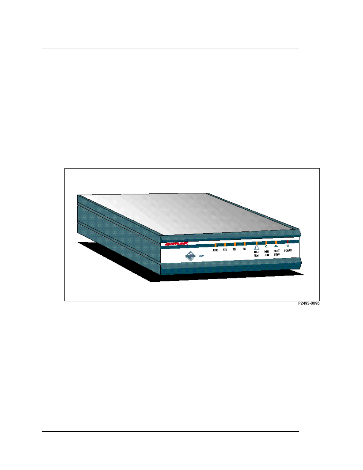
The AirLink Pro 64S is a compact table top unit (see Figure 1-1), which can also
be rack mounted.
1-2
Figure 1-1
AirLink Pro 64S- Full View
Rev. B - 2/97
Page 20

Features and Capabilities
The AirLink Pro 64S supports a range of sophisticated control capabilities and
options, including:
❚ Flexible, interactive user interface through an ASCII terminal
❚ Easily modified configuration parameters
❚ Software configuration
❚ Built in testing
❚ Operating range up to 30 miles (50 km) between units (subject to local radio
regulations)
❚ Local and remote monitoring, diagnostic, and maintenance capabilities
❚ Every radio-frequency (RFD) burst verified by an error-checking algorithm
AirLink Pro 64S Installer’s Guide
Product Description
❚ Modem dial-in/dial-out control at the network management ports
❚ RS-232, V.35, and EIA-530 interfaces supported with one unit
❚ Burst sync compatibility with AirLink One S-Band modems
❚ Redundant burst sync
❚ Optional Rugged Enclosure
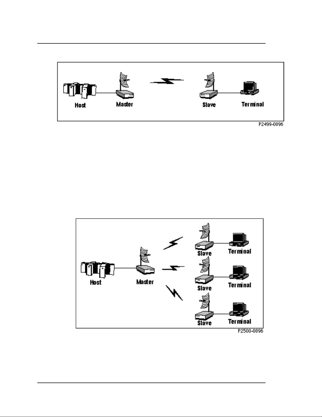
In a typical redundant installation, an AirLink Pro 64S operates in a point-topoint or point-to-multipoint environment. In a point-to-point setup, there is one
master and one slave modem linked by radio. The master modem is the bursttiming synchronizer of the radio link. The master sends a timing code to the
slave with transmission bursts. Once the slave receives a complete burst, it
turns on its transmitter and transmits its burst. This scheme provides a fullduplex, radio-to-radio communication that follows a Ping-Pong analogy.
Rev. B - 2/97
1-3
Page 21
AirLink Pro 64S Installer’s Guide
Product Description
Figure 1-2
Point-to-Point Application Showing Master/Slave Configuration
In a point-to-multipoint setup, the Pro 64S modems provide a radio link
between a host computer and two or more remote terminals. The terminals are
controlled by the host with a poll-select communication protocol that is
transparent to the AirLink modems. In this case, polling is the process of
addressing the remote terminals by the host computer’s software. The master
modem is the burst-timing synchronizer of the radio link. The master sends a
timing code to the slave with transmission bursts. The slave synchronizes to
this timing reference and sends transmission bursts back. This scheme provides
a full-duplex, point-to-point session within a point-to-multipoint application.
As shown in Figure 1-3, the host computer can poll one terminal via the
AirLinks while transferring data to another.
1-4
Figure 1-3
Point-to-Multipoint Application
Rev. B - 2/97
Page 22

AirLink Pro 64S Antenna
The antenna choices can include an 8 dBi Omnidirectional antenna or a 24 dBi
semi-parabolic Directional antenna. Refer to the AirLink Site Planning Guide
for different antenna options.
Network Management Ports
The AirLink Pro 64S ASCII terminal user interface is an RS-232 interface that
allows a terminal device or personal computer to control and monitor AirLink
Pro 64S operation at either end of the link. The connection to the RS-232
interface can be either a direct connection (device to port), or an indirect
connection (device to modem to port).
Programmed Configuration Parameters
The AirLink Pro 64S operation is governed by user-selectable configuration and
control parameters that reside in the non-volatile memory of the unit. These
parameters are displayed and controlled through a terminal device that can
access both the local and remote unit. When power is lost and then restored,
the system reconfigures itself from its protected configuration database.
AirLink Pro 64S Installer’s Guide
Product Description
Refer to Chapter 3, Configuration, for more information on changing
configuration parameter settings.
A long-life lithium battery protects all system configuration settings during
power losses. The battery is integrated into the non-volatile memory /realtime clock circuitry on the digital module in the AirLink Pro 64S. It has a 10year storage life (in the absence of Power to the AirLink Pro 64S). However, a
battery about to expire will result in loss of all configured parameters and
revert back to the default configurations.
WARNING The component containing the lithium battery is NOT a customer-replaceable part. Do not
expose the lithium battery cell by opening the component. Do not attempt to recharge the
battery. Do not dispose of the component by fire. The lithium battery could explode if
mistreated.
Monitoring and Diagnostic Capabilities
The AirLink Pro 64S system constantly monitors the quality of the wireless
link, checking the receive RFD signal level, bit errors, and many other critical
factors. This information goes into an internal database of status and
performance information that the AirLink Pro 64S uses, in part, to derive the
Rev. B - 2/97
1-5
Page 23

AirLink Pro 64S Installer’s Guide
Product Description
events that are stored in the event queue. As alarm events occur, they are
signaled through indicators on the front panel of the modem and are entered in
the event queue.
Using the terminal user interface, you can query either the local unit or the
remote unit for status, performance and alarm information, and make
configuration changes for either the local or remote end of the link.
The AirLink Pro 64S also provides built-in bit error testing and loopback tests
that may be used to isolate problems. You can initiate tests in the local unit or
in the remote unit through the terminal user interface.
Refer to Chapter 4, Operations and Maintenance, for information on monitoring
operation and using diagnostic tools and procedures.
AirLink Pro/AirLink One Compatibility
AirLink Pro 64S modems are designed to operate in the same environments as
AirLink One modems. They are compatible in the sense that adjacent links
emanating from a Hub Site can be implemented using different generations of
AirLink modems. However, due to different burst structures in the TDD overthe-air protocol, an AirLink Pro 64S modem cannot communicate in the same
link with an AirLink One 64S modem.
There are compatibility issues to consider when AirLink Pro 64S and AirLink
One modems are configured together to avoid mutual interference.
❚ Burst Synchronization
❚ Radio Frequency Environment
The considerations necessary for Burst Synchronization are discussed in
Chapter 2, Installation and System Administration in the Burst
Synchronization Section.
The AirLink Pro 64S has two commands, RF Plan and Range, that must be
configured for AirLink One compatibility. These commands are discussed in
Chapter 3, Configuration in the Configuring the RF Link section.
1-6
Rev. B - 2/97
Page 24

C
HAPTER
HAPTER
C
Installation
Installation
This chapter outlines general planning and the procedures for
unpacking, and installing the AirLink Pro 64S hardware, connecting
cables, and performing power-up checks. This chapter also contains
important instructions regarding safety in setting up the AirLink Pro
64S system.
2
2
Inside this chapter:
Overview .................................................................................2-2
Unpacking ...............................................................................2-2
Identifying Physical Features ............................................2-3
Site Preparation...................................................................2-5
Setting Up the System .......................................................2-6
Checking Operation ...........................................................2-28
Rev. B - 2/97 2-1
Page 25

AirLink Pro 64S Installer’s Guide
Installation and System Administration
Overview
This chapter touches briefly on the general technical requirements of antenna
and RF transmission line installation, but mainly focuses on the task of
installing the AirLink Pro 64S system at each end of the communication link,
integrating all of the equipment, and performing a system check and alignment
before turning the system over to normal customer traffic.
A typical AirLink Pro 64S system is made up of the following components:
❚ AirLink Pro 64S
❚ antenna
❚ optional system components
Depending upon your system plan, you will be installing all or some of these
AirLink Pro 64S system components at each end of a link. The following sections
describe both required and optional system components.
Unpacking
The first step in the installation process is to take all of the materials out of
the shipping carton(s) and make sure that you have everything shown on the
packing list(s). If something is missing, contact your local distributor. Inspect
the unit for any possible damage. If you discover shipping damage, repack the
unit and notify the shipping representative.
NOTE Save the shipping cartons and packing materials. You will need the carton and materials if
you ever need to ship your equipment elsewhere.
After unpacking and confirming the contents of the shipment, place the AirLink
Pro 64S system components on a flat surface that allows enough space to work
around them.
2-2
Rev. B - 2/97
Page 26
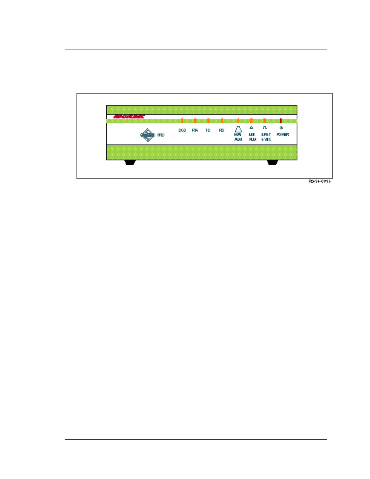
Identifying Physical Features
Figure 2-1
AirLink Pro 64S Front Panel
AirLink Pro 64S Installer’s Guide
Installation and System Administration
Front Panel
The AirLink Pro 64S front panel (Figure 2-1) consists of a metal panel that
contains two clusters of indicators identified with graphical icons and labels.
The two clusters have four indicators each. Table 2-1 lists the front panel LEDs
and describes their functions.
Rev. B - 2/97
2-3
Page 27

AirLink Pro 64S Installer’s Guide
Installation and System Administration
Table 2-1
AirLink Pro 64S Front Panel Indicators
Name Color Function
DCD Green When ON, indicates that a good data communications
RTS Green Indicates that RTS is asserted internally or externally.
TD Green Indicates that the unit is transmitting data (in the form
RD Green Indicates that the unit is receiving data (in the form of
Major Alarm Red When ON, indicates that one or more of the following
Minor Alarm Yellow When ON, indicates that one or more of the following
Burst Sync Green When ON, indicates that the unit is the burst sync
Power Green Indicates that primary power is supplied to the
channel has been established
of ones) to the far-end unit.
ones) from the far-end unit.
events has occurred:
-Transmit Power Below Threshold
- DTE Interface Voltage Error
- Radio Sync Loss
- System Reset
- No Burst Sync Source
events has occurred:
- RSSI Below Threshold
- VSWR Above Threshold
- RSQ Below Threshold
- Primary Burst Sync Source Loss
- Backup Burst Sync Source Loss
- 1-HR Errored Seconds Threshold Exceeded
- 1-HR Unavailable Seconds Threshold Exceeded
- 24-HR Errored Seconds Threshold Exceeded
- 24-HR Unavailable Seconds Threshold Exceeded
source.
equipment.
2-4
Rear Panel
The AirLink Pro 64S rear panel (Figure 2-2) consists of a metal panel containing
two external equipment connectors, one terminal block, an AC power connector
and an N-type antenna connector. Table 2-1 lists the rear-panel connectors and
describes their functions.
Rev. B - 2/97
Page 28
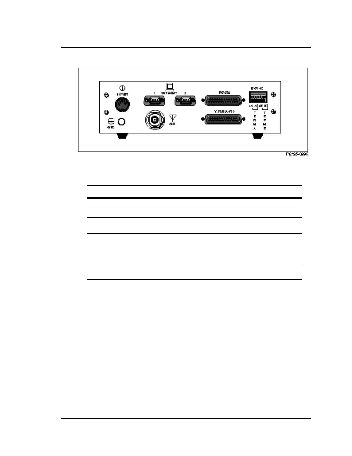
Figure 2-2
AirLink Pro 64S Rear Panel
Table 2-2
AirLink Pro 64S Rear Panel Connectors
Connector Type Function
AirLink Pro 64S Installer’s Guide
Installation and System Administration
Power 5-pin DIN female Power connection.
Antenna N-type female Antenna connection
Network Management
Ports
DTE DB 25 female for
Burst Sync 6-Pin Captive Wire
Site Preparation
Because of the special planning requirements associated with installing a
microwave system, you should review some of the general guidelines regarding
installation preparation to ensure that the site you are considering is suitable
to the purpose. For details on Site Planning, refer to the AirLink Site Planning
Guide.
General Physical and Environmental Characteristics
DB 9 male
connectors
RS-232 interface
DB 25 female for
V.35 and EIA-530
Terminal
For connecting a modem or terminal to the
AirLink Pro 64S.
DTE connection
(Note: These are DCE emulating ports.)
Burst Sync Connection
Rev. B - 2/97
The AirLink Pro 64S radio unit measures 8.3 inches wide (21.083cm), 2.6 inches
high (6.60cm), and 10 inches deep (25.4cm), and weighs approximately 5 pounds
(2.3 kilograms).
2-5
Page 29

AirLink Pro 64S Installer’s Guide
Installation and System Administration
Lightning Protection
If the AirLink Pro 64S system is being installed in an area where lightning is a
problem, primary protection, such as gas tubes or spark gaps, is required (Cylink
distributors can provide these). For more details on lightning protection refer to
the AirLink Site Planning Guide.
Power Requirements
The AirLink Pro 64S Power Specifications are listed in the table below.
Table 2-3
Voltage Requirements
Parameter Specifications
External AC power Supply
Input
Output
100-250 VAC @ 50/60 Hz
+5, +/- 12 VDC, cable terminated with 5-pin
male DIN Connector
Maximum Power consumption
(Power Supply plus AirLink)
NOTE Power supplies are available as options from Cylink and distributors.
AC Power Supply - 23W
DC Power Supply - 21W
Setting Up the System
The following sections outline the procedures for installing, cabling, and
bringing up an AirLink Pro 64S system. Some of the steps require special
knowledge, experience, and tools; some of the installation steps may require
help from another person.
Installing the Antenna
Antennas are generally installed by persons who have the knowledge,
experience, and tools to handle the somewhat specialized task. The following
sections are intended as a general summary of the process, and not as a complete
description. A successful antenna installation effort is the culmination of site
and route preparation and path analysis. For a detailed description of Path
Analysis and antenna options refer to the AirLink Site Planning Guide .
2-6
Rev. B - 2/97
Page 30
AirLink Pro 64S Installer’s Guide
Installation and System Administration
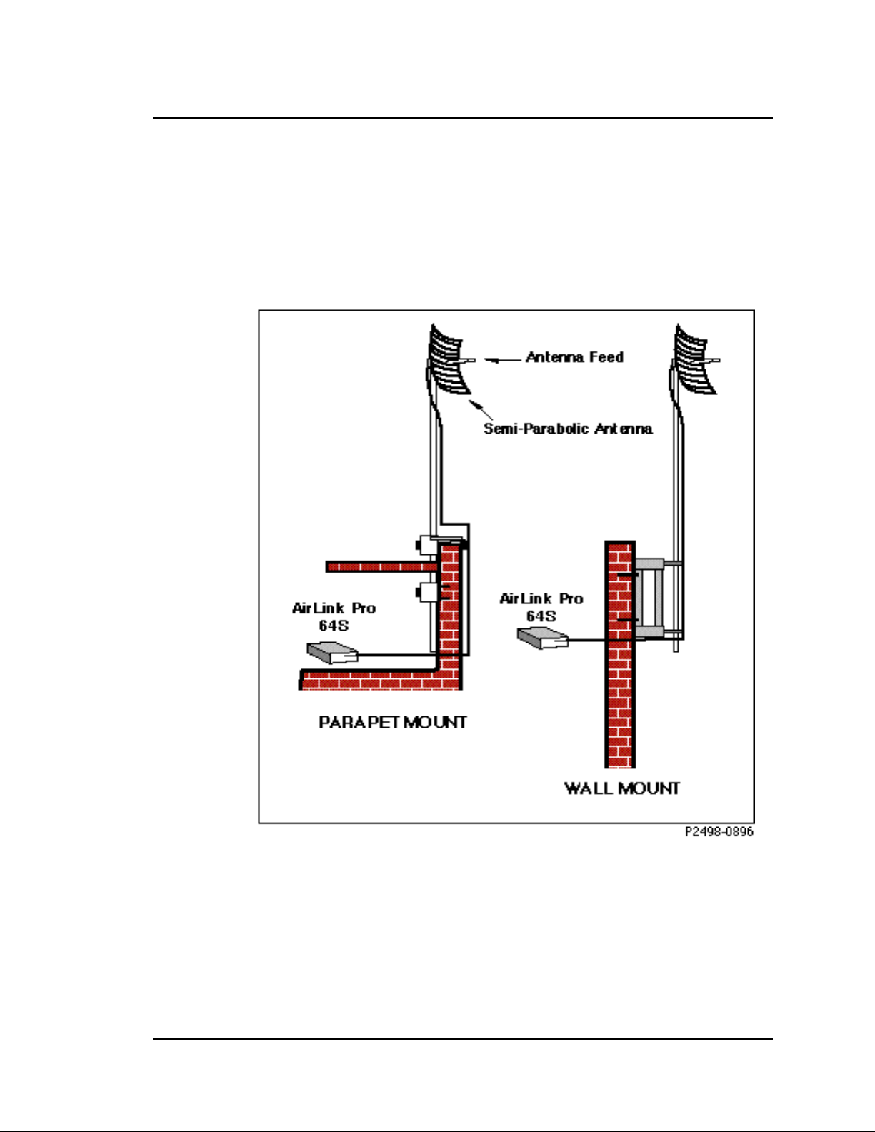
Typical Antenna Mounts
An antenna for a microwave system such as the AirLink Pro 64S is typically
equipped with mounting hardware that allows the antenna to be attached to a
length of pipe (or stub mast) that can then be mounted in several ways,
depending upon user requirements, site conditions, and local building codes (see
Figure 2-3).
Rev. B - 2/97
Figure 2-3
Typical Antenna Mounts
System Grounding
Direct grounding of the antenna, mast, and tower provides some protection
against lightning strikes and static buildup. A direct electrical connection
should be made to a suitable grounding rod at the base of the tower or mast using
2-7
Page 31

AirLink Pro 64S Installer’s Guide
Installation and System Administration
at least one-inch wide copper grounding strap, or its equivalent, and noncorrosive hardware. For details and safety standards, consult the appropriate
electrical code or a similar document. Use lightning arrestors in appropriate
places.
Aligning the Antenna
In order for an AirLink Pro 64 pair to operate correctly, the local antenna and
the remote antenna must be aligned so that the signals from one antenna are
aimed directly at the center of the other antenna. Correct antenna alignment
maximizes the signal received at both ends of the radio link. The antenna
alignment procedure is outlined at the end of this chapter.
WARNING The AirLink Pro 64S should be grounded before any other connections are made to it. This
includes power, DTE, and Network Management port connections.
Installing the AirLink Pro 64S
Connecting the Antenna Cable
To connect the antenna cable to the AirLink Pro 64S:
1. Locate the N-type connector on the rear panel of the AirLink Pro 64S (see
Figure 2-2).
2. Plug the RF cable connector firmly into the N-type jack connector and handtighten the cable connector shell onto the jack connector collar.
3. Verify that the cable connector is seated securely and that the cable is not
kinked.
DTE Line Connection
1. The AirLink Pro 64S supports RS-232, EIA-530, and V.35/V.11 interfaces.
Two separate DB 25 female connectors are provided on the rear panel for
the three interfaces.
NOTE Cable/connectors are available from Cylink and Cylink distributors.
2. Locate the DTE connectors on the AirLink Pro 64S rear panel (see Figure 2-2)
and use a shielded cable to secure the hold-down hardware.
2-8
3. Ensure that the cable is securely held by the connector.
Rev. B - 2/97
Page 32

AirLink Pro 64S Installer’s Guide
Installation and System Administration
Connecting the Power
The AirLink uses an external power supply that is provided with the modem.
1. Locate the power connector on the rear panel of the modem.
2. Plug the 5-pin DIN connector of the power supply cable into the modem.
3. Plug the AC power cord into the power supply and then into the grounded
electrical outlet.
WARNING To avoid the danger of electrical shock or power loss, ensure that the power cord is
securely seated in the receptacle on the modem. This equipment is designed to work with
electrically grounded systems. The product’s AC power cord ends in a three-pole
grounding plug. Do not use a three-pole to two-pole adapter with the plug. Verify that
the outlet you intend to use is properly installed and grounded; the outlet used must
comply with the local electrical code for the country it is installed in. To ensure your
safety, only connect the power cable to a properly grounded outlet.
Network Management (Terminal Connection)
On the rear panel of the AirLink Pro 64S are two Network Management ports
(DB 9 male). Modems can be connected via Network Management port #1 and a
simple ASCII terminal or personal computer can be connected via port #2 to
monitor and configure the AirLinks operation.
Figure 2-4
Terminal Connection to the AirLink Pro 64S
Rev. B - 2/97
2-9
Page 33

AirLink Pro 64S Installer’s Guide
Installation and System Administration
NOTE The Network Management ports are “wired” as DTE (Data Terminal Equipment). This
allows for a standard “straight through” cable connection for any modem (modems are
wired as DCE Data Communications Equipment). Since the terminal or PC and the Network
Management ports are “wired” as DTE, the user must supply a “null modem” cable when
connecting a PC or a terminal to the AirLink Pro 64S.
Terminal Setup Requirements (ASCII Terminal)
The following information describes the simple steps neccessary to configure a
terminal in order to perform antenna alignments. Further information on
terminal usuage for setting each link parameter will be discussed in later in
this Chapter.
Before connecting the ASCII terminal to the unit, configure the terminal with
the following parameters:
Terminal Mode = VT100
Column = 80
Autowrap = ON
Monitor Mode = OFF
Cursor Keys = Normal
Newline Mode = ON
Character Set = DEC Supplemental
Key Code = ASCII
Break key = ON
Minimum Break Length = 2 character times (17 msec.)
Data/Parity = 8/No Parity
Stop Bits = 1
Transmit Rate = 19200, 9600, 4800, 2400, or 1200 bps
Auto Answerback = OFF
Comm = FDX (No Echo)
RS232 Data Leads
Local Echo = OFF
2-10
To connect the terminal, follow these steps:
1. Connect the terminal (or a computer in terminal emulation mode) to the
Network management port as described in Chapter 2.
2. Turn on the terminal; adjust contrast and brightness as required.
The AirLink Pro 64S terminal interface software contains an autobaud feature
that automatically attempts to detect the operating baud rate of the attached
terminal device.
3. Press <Break> then <Return> on the terminal keyboard.
Rev. B - 2/97
Page 34

Installation and System Administration
11
Pressing <Break> at the terminal puts the AirLink Pro 64S terminal interface
software in “hunt” mode, where it looks for carriage return (<Return>)
characters from the attached terminal. If the terminal is set for 19200, 9600,
4800, 2400, or 1200 bps, the terminal interface software learns the operating
baud rate by starting at 19200 bps and dropping to the next lower speed in the
sequence for each press of the <RETURN> key until it recognizes a <Return>
character. When the software detects a <Return> character, it displays the
AirLink Pro command-line prompt:
AIRLINK PRO 64S>
NOTE Lap top computers do not support the break function.
Pressing <Break> puts the terminal interface software back into hunt mode. If
the prompt does not appear, press <Break>once, then press <Return>
repeatedly at one second intervals until the AirLink Pro 64S prompt appears. If
the prompt doesn’t appear after pressing <Return> six times, press <Break>
and try again.
AirLink Pro 64S Installer’s Guide
Terminal Setup Requirements (for personel computers with Windows™)
A personal or laptop computer can be used as a dummy terminal to configure,
status, and acquire information from the AirLink Pro 64S radio. The serial
communication port (com1 or com2) of the computer must be connected to either of
the two Network Management Ports on the rear panel of the unit. There are
other communication software packages like Procomm™ that can be used to
emulate a dummy terminal. The instructions given below are a guide to using
the Microsoft Windows terminal emulation software.
Using the mouse buttons double click on the ACCESSORIES icon under the
Program Manager of Windows. Double click on the TERMINAL icon. Pull down
the menu under Settings near the top of the screen, and single click on Terminal
Emulation. Select DEC VT-100 [ANSI] (see Figure 2-4 ) then single click on OK.
Figure 2-5
Terminal Emulation
Now go back to settings and single click on Terminal Preferences, and set up the
terminal parameter as follows:
Rev. B - 2/97
2-
Page 35

AirLink Pro 64S Installer’s Guide
Installation and System Administration
Figure 2-6
Terminal Preferences
Single click on OK to enter any changes made to these settings or click on Cancel
to exit without change. While remaining under Settings, select Communications
and set up the serial port as follows:
2-12
Rev. B - 2/97
Page 36

AirLink Pro 64S Installer’s Guide
13
Installation and System Administration
Figure 2-7
Communications
This software works best at data rates of 4800 baud or lower. To change the
baud rate hold down the Control and Break key simultaneously for 10 seconds.
This will send a command to the AirLink Pro 64S radio to search through and
match the baud rate of interface with the baud rate of the terminal.
Configuration of the Serial Communication Port
Go to the Program Manager in Windows by typing “WIN” at the C: >\ prompt.
Single click on the MAIN icon, then single click on the CONTROL PANEL icon
which shows the normal or default settings for the mouse, keyboard, and serial
communication ports. Double click on the PORT icon, then select the
communication port number that will be displayed (See Figure 2-7).
Rev. B - 2/97
2-
Page 37

AirLink Pro 64S Installer’s Guide
Installation and System Administration
Figure 2-8
Ports
For example: Single click on COM1 (communications port 1), then click on
Settings. The current settings of baud rate, data bits, parity, stop bits, and flow
control are displayed for com1.
2-14
Figure 2-9
Settings for Com1
A single click on ADVANCED will display the advanced settings of the
communication port which are Base I/O Port Address and IRQ Line (Interrupt
setting).
Rev. B - 2/97
Page 38

AirLink Pro 64S Installer’s Guide
15
Installation and System Administration
Figure 2-10
Advanced Settings for Com1
For most applications the default settings for both the COM1 and COM2 are as
follows.
Serial Port Base address Interrupt Request Line (IRQ)
COM1 0X3F8 4
COM2 0X2F8 3
Single click on OK to enter any changes made to these settings or click on Cancel
to exit without change.
Usually these settings are not changed unless changes are made to the system,
such as the addition of a high speed I/O card or internal modem. When the
computer is running an application software it is very important that all the
interfaces and communication ports be set up correctly. If a laptop or a personal
computer does not have a mouse you can choose or select specific settings within
each menu by pressing the tab key repetitively to move through each option.
Pressing <TAB> + < CURSOR> keys will allow you to step through each
option and make changes as required.
A terminal device or a personal computer may have specific data cabling
requirements (refer to Appendix B, Specifications, for connector pin
assignments), and usually requires a grounded alternating current power outlet.
In a hub installation involving a number of AirLink Pro 64S pairs, the terminal
device can be “shared” across all the AirLink Pro 64S systems by using a
terminal switching device.
Remote Modem Connection
A remote terminal or personal computer can be connected to Network
Management Port #1 on the rear panel of the AirLink Pro 64S unit through a
modem (see Figure 2-11). A modem typically requires a dedicated telephone
line with a modular RJ-11 jack as well as a source of power, usually a standard
115 VAC or 230 VAC grounded outlet.
Rev. B - 2/97
2-
Page 39

AirLink Pro 64S Installer’s Guide
Installation and System Administration
NOTE AirLink power cords are available to match the power outlets in most countries.
NOTE To avoid ground loops, use the same power outlet for the AirLink Pro 64S and any auxiliary
equipment, like a terminal or computer.
Figure 2-11
Modem Connection to the AirLink Pro 64S
Batch File Handling
The user can configure the unit by executing commands through a batch file. The
user needs a Windows terminal emulator or a serial communications package
such as Procomm. The batch file can be used to execute local SET commands only
(user cannot issue remote commands via a batch file). It is important that the
user verify the proper execution of GET and SET commands manually before
executing the batch file. This indicates that the unit is functional.
Procomm:
1. Power up the unit. Log in and verify that the GET and SET commands work.
2. Choose Alt-S option in order to select the upload parameters.
3. Select option # 4...delay between characters...suggested value: 25.
2-16
Rev. B - 2/97
Page 40

AirLink Pro 64S Installer’s Guide
17
Installation and System Administration
4. Select option # 5...delay between lines...suggested value: 100 (Esc gets you
out of the setup menu).
5. Press the PageUp key to bring up a menu that gives you several options.
6. Choose Option 6 (ASCII Upload). Procomm prompts you for the filename.
7. Enter the name of the batch file holding the configuration commands.
NOTE Procomm Plus software does not work with the AirLink Pro 64S at this time.
Windows Terminal Emulator:
1. Power up the unit and wait for the POST messages.
2. Login and verify that the GET and SET commands work.
3. From the Setting menu, select the Text Transfer option.
4. Set the following parameters:
Delay between characters : 1/10 sec
Delay between lines : 25/10 sec
5. From the Transfer menu select Send Text File. Enter the name of the text
file that contains the configuration commands.
NOTE The delay between character values are dependant upon the speed of your PC.
You should see each command being executed on the local unit. The command
will be followed by the unit’s response based on whether the command was
executed. If the terminal program sends a command to the local unit before the
local unit is ready for the next command, the command may be dropped.
Burst Synchronization
When you have either a hub configuration or a repeater site (more than one
AirLink unit operating from the same central site), one of the units must be set
up as the source for burst synchronization. Refer to Chapter 3, Configuration,
for Hub and Repeater settings.
Rev. B - 2/97
2-
Page 41

AirLink Pro 64S Installer’s Guide
Installation and System Administration
Burst Sync Signal Description
The Burst Synchronization signal is used by AirLink Modems in Hub and
Repeater applications to synchronize two or more modems to a common
reference. Two types of synchronization are required: transmit burst and bit
timing synchronization. These two components are necessary to align the
transmit bursts, and to ensure that an exact number of user data bits are
generated every 8.5 millisecond Time-Division-Duplex (TDD) frame. If this
were not the case, data would be lost when the internal buffers overflowed.
The TDD over-the-air protocol used in AirLink modems is characterized by a
transmit burst followed by a receive burst, in an 8.5 millisecond frame. In order
to minimize interference between adjacent links, it is necessary to ensure that
all of the transmit bursts emanating from the hub site occur simultaneously.
This is accomplished by providing a bussed burst synchronization signal (see
Figure 2-12) to all modems at the hub site. The signal has a complex structure
that has two components. The first component is characterized by wide pulses,
which occur at 8.5 millisecond intervals. They are used by the AirLink modems
to trigger the transmit bursts and ensure the necessary time alignment. The
second component is characterized by short pulses, which occur at an 8 kHz
frequency. The pulses serve as phase reference for the AirLink modem internal
oscillator, which ensures bit timing synchronization between the modems.
2-18
Figure 2-12
Burst Synchronization Structure
Time-Division-Duplex (TDD) Burst Structure Description
The TDD over-the-air protocol used by the AirLink Pro 64S modem is designed
to provide the transport mechanism for the full-duplex user data, as well as a
separate communication channel for the remote command and status capability
(see Figure 2-13). The burst structure is shown in the figure below. This figure
Rev. B - 2/97
Page 42

AirLink Pro 64S Installer’s Guide
19
Installation and System Administration
depicts the format of a single burst, however two such bursts, a transmit and a
receive burst, are required to form a complete TDD frame. Each burst is
approximately 4 milliseconds long, which is about 40% of the TDD frame
time. The two bursts together take up 80% of the frame time, and the unused
20% is called the guard time, which is necessary to allow for the two-way
propagation delay between the two modems that form a link.
The burst is shown to be composed of five components. The Preamble (PA) is the
first part of the burst. It is necessary to allow the receiving modem circuitry to
re-acquire synchronization to the transmitting modem. The receiver must reacquire sync for each burst since it will drift in frequency slightly during the
time that no signal is present. The second component is the Unique Word (UW).
This is a unique bit pattern that is used by the transmitter to mark the start of
the payload data to the receiver. Once the receiver detects this pattern, it can
immediately begin recovering the remaining three components. The third
component is the inter-processor communication channel (COMM). This channel
provides a 1 kbps full duplex communication link between the embedded
microprocessors in the AirLink Pro modems. The channel is used to communicate
commands and to request and receive status information over the RF link. The
fourth component is the data payload (DATA), which provides a maximum 64
kbps full duplex communication channel for the user’s data. The user’s data is
carried unmodified in this burst structure, making the AirLink modem’s DTE
interface protocol-independent. Finally, the fifth component is the CyclicRedundancy Check error detection code. This 16-bit code is computed on the
transmit side, and checked on the receive side, once for every burst. When block
errors are detected they are counted, and are reported by the microprocessor.
Rev. B - 2/97
Figure 2-13
TDD Burst Structure
2-
Page 43

AirLink Pro 64S Installer’s Guide
Installation and System Administration
Installing Burst Sync Wiring
Burst synchronization minimizes near-end inter-channel interference among the
units in a hub configuration; all the hub units are synchronized in order to
transmit and receive at the same time. The burst synchronization system is
implemented with a dual external bus. Each bus consists of a differential pair
of wires, driven by a tri-stateable RS-485-type device. When multiple modems
are to be synchronized, they should be interconnected via a color coded fourwire cable. Each modem has six jacks that are electrically identical to
facilitate this interconnection.
The equipment should be physically located as shown in Figure 2-14. The
Reference and backup masters should be the first units in the chain. Figure 2-14
illustrates the connections needed for Burst synchronization at a hub site where
the A bus is used. The Reference master is the burst sync signal source, providing
it for the three Subordinate master units. If the distance between the Reference
master and the last Subordinate master is greater than 100 ft, the burst sync
bus(es) should be terminated at the last subordinate master. The termination is
done with a 100 ohm resistor (internal to AirLink) as shown in Figure 2-15. You
should ensure that that the Termination is at one end of the daisy chain and
the Burst sync source is at the opposite end. Care should also be taken not to use
multiple terminations.
2-20
Figure 2-14
Burst Sync Wiring
Burst Sync Fail-Safe Feature
The AirLink Pro provides for a burst synchronization backup scheme which uses
two buses. These are referred to as the "A" bus and the "B" bus. Use of the
backup burst synchronization bus is optional. To use the backup feature, one of
the two buses is designated as the primary burst synchronization bus and the
other is designated as the backup burst synchronization bus. One of the units at
a hub site is selected as the "Reference Master", and a second unit is selected as
Rev. B - 2/97
Page 44

AirLink Pro 64S Installer’s Guide
21
Installation and System Administration
the "Backup Master." All other units at the hub are designated as
"Subordinate Master." The burst synchronization signal on the primary bus is
provided by the Reference Master unit. When activity is lost on the primary
bus, implying that the Reference Master has failed to provide the burst
synchronization signal, the modems will use the backup burst synchronization
signal provided by the Backup Master unit. When activity is again detected on
the primary bus, the burst synchronization signal on this bus is used.
Figure 2-15
Burst Sync Backup
The Burst Sync LED is ON for the unit providing the burst synchronization
signal; this will always be either the Reference Master or the Backup Master.
Subordinate Master units never provide the burst synchronization signal.
The AirLink Pro modem unit monitors for loss of the burst synchronization
signal. When only a single burst synchronization bus is used, the loss of the
burst synchronization signal triggers a Major Alarm. The Major Alarm LED is
turned ON, and an alarm message is generated in the event log. When both
burst synchronization buses are being used, and both primary and backup burst
synchronization signals are lost, a Major Alarm is generated. The Major Alarm
LED is turned ON, and an alarm message is generated in the event log. If either
the primary or backup burst synchronization signal is lost, a Minor Alarm is
generated. The Minor Alarm LED is turned ON, and an alarm message is
generated in the event log.
To configure all the units at a primary hub site to use the primary burst
synchronization bus only, follow these steps:
1. Designate one unit to be the Reference Master unit. Type
Rev. B - 2/97
2-
Page 45

AirLink Pro 64S Installer’s Guide
Installation and System Administration
AIRLINK PRO 64S > set application 4
2. Designate all the other units to be Subordinate Master units. For each unit,
type
AIRLINK PRO 64S> set application 6
3. To designate a single burst sync system, at each unit in the hub, type
AIRLINK PRO 64S > SET HUB_SYNC SINGLE
4. Wire the units as shown in Figure 2-14.
To configure all the units at a primary hub site to use the backup burst
synchronization feature, follow these steps:
1. Designate one unit to be the Reference Master unit. For this unit, type
AIRLINK PRO 64S > Set Application 4
2. Designate a second unit to be the Backup Reference Master unit. For this
unit, type
AIRLINK PRO 64S > Set Application 5
3. Designate all the other units to be Subordinate Master units. For each unit,
type
AIRLINK PRO 64S > Set Application 6
4. To designate a dual burst sync system, at each unit in the hub, type
AIRLINK PRO 64S> SET HUB_SYNC DUAL
5. Wire the units as shown in Figure 2-15.
To configure units in a secondary hub site, all the above steps apply except that
either a Slave modem in a point-to-point link or a Slave modem in a point-tomultipoint link is used in place of the Reference Master unit.
Normal Operation of Backup Burst Synchronization
The Backup Burst synchronization scheme is used in hub and repeater
configurations. The burst synchronization signal is provided on two buses, Bus A
and Bus B. The primary burst sync signal is provided by the Reference Master
unit on Bus A. The Backup Burst Synchronization signal is provided by the
Backup Master unit on Bus B.
2-22
Rev. B - 2/97
Page 46

AirLink Pro 64S Installer’s Guide
23
Installation and System Administration
Table 2-4
Normal Burst Sync Activity
Source Reaction
Reference Master Provides burst sync signal on Bus A
Uses own burst sync signal
Burst Sync Source LED is ON
Backup Master Provides burst sync signal on Bus B
Uses burst sync signal from Bus A
Burst Sync Source LED is OFF
Subordinate Master(s) Uses burst sync signal on Bus A
Burst Sync Source LED is OFF
Activity Lost on Bus A Only
This condition occurs if the Reference Master unit malfunctions or the burst sync
connection on Bus A is broken. It is detected by all units at the hub except for the
Reference Master unit. The Reference Master unit cannot monitor its own burst
sync status. The technician should power down the Reference Master Unit or
remotely enable its “RF Sleep” command, until the problem is located. It may
still be transmitting and can cause near-end inter-channel interference since all
other units are using a different burst sync signal.
Table 2-5
Bus A Activity Lost
Source Reaction
Reference Master Uses own burst sync signal
Burst Sync Source LED is ON
Backup Master Provides burst sync signal on Bus B
Uses own burst sync signal
Burst Sync Source LED is ON
Minor Alarm LED is ON
Event Queue contains “Primary Burst
Sync Source Loss” message
Subordinate Master(s) Uses burst sync signal on Bus B
Burst Sync Source LED is OFF
Minor Alarm LED is ON
Event Queue contains “Primary Burst
Sync source loss” message
Activity Lost on Bus B Only
This condition occurs if the Backup Master unit malfunctions or the burst sync
connection on Bus B is broken. It is detected by all units at the hub except for the
Backup Master unit. The Backup Master unit cannot monitor its own burst sync
status.
Rev. B - 2/97
2-
Page 47

AirLink Pro 64S Installer’s Guide
Installation and System Administration
Table 2-6
Bus B Activity Lost
Source Reaction
Reference Master Provides burst sync signal on Bus A
Backup Master Uses burst sync signal on Bus A
Subordinate Master(s) Uses burst sync signal on Bus A
Activity Lost on Bus A and Bus B
Table 2-7
Bus A and Bus B Activity Lost
Uses own burst sync signal
Burst Sync Source LED is ON
Minor Alarm LED is ON
Burst Sync Source LED is OFF
Burst Sync Source LED is OFF
Minor Alarm LED is ON
Event Queue contains “Backup Burst
Sync Source Loss” message
Source Reaction
Reference Master Uses own burst sync signal
Burst Sync Source LED in ON
Minor Alarm LED is ON
Event Queue contains “Backup Burst
Sync Source Loss” message
Backup Master Uses own burst sync signal
Burst Sync Source LED is ON
Minor Alarm LED is ON
Event Queue contains “Primary Burst
Sync Source Loss” message
Subordinate Master(s) Burst Sync Source LED is OFF
Major Alarm LED is ON
Event Queue contains “No Burst Sync
Source” message
2-24
Rev. B - 2/97
Page 48

AirLink Pro 64S Installer’s Guide
25
Installation and System Administration
Burst Synchronization Compatibility with AirLink One Modems
The AirLink Pro 64S uses a burst synchronization signal that is compatible with
the signal used in the AirLink One S-band 64kbps, 128kbps, and 256kbps models
and AirLink One L-band models. A hub configuration may contain both AirLink
Pro and AirLink One units. AirLink One units, however, cannot take advantage
of the backup burst synchronization feature. For the burst synchronization
signal, the AirLink One models use a different connector and cable than those
used on the AirLink Pro 64S. The following section describes the procedure to
successfully connect AirLink Pro and AirLink One units for burst synchronization
in a hub configuration. You will need an RS232 DB25 (Female) to BNC (Male)
converter, RS232 DB25 (Male) to RS422 terminal block converter (see Figure 2-
14) and a pair of single wires (converters can be ordered from Cylink
distributors).
The RS232 and RS422 terminal block converter, Telebyte Model number 285M,
must be properly configured before use. A two position switch accessible from
the top of the unit should be set to the “DCE” position. Also, the five position
dip switch next to the terminal block should have the following settings: SW1
through SW4 open, and SW5 closed.
Figure 2-16
Burst Sync Compatibility (AirLink One unit providing Burst Sync)
Rev. B - 2/97
2-
Page 49

AirLink Pro 64S Installer’s Guide
Installation and System Administration
AirLink One Unit Providing Burst Synchronization Signal
1. Connect the BNC cable marked “SEND” of the RS232-to-BNC converter to
the "SYNC" connector of the AirLink One.
2. Connect the DB25 female end of the RS232-to-BNC converter to the DB25
male end of the RS232-to-RS422 converter.
NOTE The cable and connectors are available for purchase from Cylink or Cylink distributors.
On the terminal block end of the RS232 to RS422 converter, there are provisions
for two pairs of wires. One pair is used when the AirLink One unit is generating
the burst synchronization signal to the other units in the hub. The other pair is
used when an AirLink Pro unit is providing the burst synchronization signal
(See the next section).
3. Connect one end of a single wire to the designated "T+" terminal of the
terminal block and the other end to the AirLink Pro unit's "+A" terminal.
Connect one end of a second single wire to the designated "T-" terminal of the
terminal block and the other end to the AirLink Pro unit's "-A" terminal.
AirLink Pro Unit Providing Burst Synchronization Signal
1. Connect the BNC cable marked "RECEIVE" of the RS232-to-BNC converter
to the "SYNC" connector of the AirLink One.
2. Connect the DB25 female end of the RS232-to-BNC converter to the DB25
male end of the RS232-to-RS422 converter.
3. Connect one end of a single wire to the designated "R+" terminal of the
terminal block and the other end to the AirLink Pro unit's "+A" terminal.
Connect one end of a second single wire to the designated "R-" terminal of
the terminal block and the other end to the AirLink Pro unit's "-A"
terminal (see Figure 2-15).
2-26
Rev. B - 2/97
Page 50

AirLink Pro 64S Installer’s Guide
27
Installation and System Administration
Figure 2-17
Burst Sync Compatibility (AirLink Pro unit providing Burst Sync)
Rev. B - 2/97
2-
Page 51

AirLink Pro 64S Installer’s Guide
Installation and System Administration
Checking Operation
At start-up an AirLink Pro 64S pair will attempt to:
❚ establish the radio link between the two radio units, and
❚ begin transferring data
When each radio unit is powered up, it performs a power-on self-test that
determines whether the unit’s hardware and software are operating within
the required limits. When the test succeeds, the designated master unit begins
transmitting, in an attempt at establishing an RF link with the slave unit.
Power-up LED Sequence
The boot-up process consists of the unit performing several self-tests (described
below). All LEDs will light at one time or another, so this is a visual check
that they are all working. The boot-up time, defined as the time for the unit to
complete the boot-up process, is 15 seconds.
All the LEDs light up when Xilinx is loaded successfully.
Table 2-8
LED Indicators
Indicator Signifies
RD EPROM Checksum
TD Xilinx EPROM Checksum
RTS LED NVRAM
DCD Configuration databases are
checked
Hardware initialization
Power LED Power is on
Burst Sync Source Boot up is successful
Minor Alarm LED RAM test in progress
Major Alarm LED Xilinx loading in progress
If a unit is powered up with the factory default configuration, the following
LEDs are ON when the unit successfully completes the boot-up process: Power,
2-28
Rev. B - 2/97
Page 52

AirLink Pro 64S Installer’s Guide
29
Installation and System Administration
Burst Sync Source, RD and TD. A few seconds later, the Major Alarm LED comes
ON, followed by the Minor Alarm LED.
Error Codes
When an error code is detected, a message is entered into the AirLink Pro 64S
Error Code Queue. If the RAM Test fails then the Minor Alarm LED stops
flashing and the Burst Sync LED lights up. If Xilinx loading fails, the Major
Alarm LED remains lit while the other LEDs are off. If the EPROM Checksum
test, the Xilinx EPROM test or the NVRAM test fails, then the corresponding
LED remains lit. Refer to Table 2-7 for Error Code Definitions. In such
situations you are advised to call your local distributor or Cylink Customer
Support.
Table 2-9
Error Codes
Message Description
Minor Alarm LED is OFF
Burst Sync LED is ON
Major Alarm LED is ON Xilinx loading failed.
RD LED is ON EPROM checksum test failed.
TD LED is ON Xilink EPROM test failed.
RTS LED is ON NVRAM test failed.
CAUTION The AirLink Pro 64S is not field repairable! Attempting to replace components will
automatically void the warranty. For out of warranty situations this usually increases the
cost of repair significantly.
RAM test failed.
Initial Unit Configuration
Because all AirLink Pro 64S units leave the factory configured as slave units in
a point-to-point configuration, be sure to configure one of the units as a master.
In a new point-to-point link installation, the configuration on one end must be
Master Unit in a Point-to-Point Link.
In a new hub installation, the units at the hub must all be masters, and the
corresponding remote units must be slaves. At a hub, set up each individual link
first as a point-to-point link and then align each link separately with all the
other AirLink Pro 64S units turned off. After all the link pairs have been
Rev. B - 2/97
2-
Page 53

AirLink Pro 64S Installer’s Guide
Installation and System Administration
configured and aligned as point-to-point links, you can then change
configurations for hub operation.
In a new repeater installation, treat each link segment as a point-to-point link,
progressing from the near-end to the far-end sites. After all the link pairs
have been configured and aligned as point-to-point links, you can then change
configuration for repeater operation.
Each type of application has been assigned a specific number for configuration
purposes. For more information about Applications and Burst Synchronization,
refer to “Application” in the ‘Setting Link Parameters’ section of Chapter 3,
Configuration.
Because there is no radio link until the AirLink Pro 64S pairs have been
configured and the antennas aligned, all system configuration must be done
individually at each unit. Once there is a radio link between the units of an
AirLink Pro 64S pair, the remote unit can be configured from the local site across
the radio link.
To configure one end of the link as a master:
1. Connect a terminal to the Terminal port on one of the two AirLink modems .
The terminal must be set up to operate according to the attributes described
in “ Terminal Connection,” earlier in this chapter.
2. Type the following command at the prompt:
AIRLINK PRO 64S> set application 2
The text you type is shown in boldfaced type; be sure to include spaces as
shown.
3. To verify the configuration change, type the following command at the
prompt:
AIRLINK PRO 64S> get configuration
The terminal displays the configuration of the unit, similar to the
following:
AIRLINK PRO 64S> Get Configuration
Site Name:
Application: 2. Master Unit in a Point-to-Point Link
PN Code: 1
RF Channel Plan: 20 channels
RF Channel: 1
RF Frequency: 2404.468
2-30
Rev. B - 2/97
Page 54

AirLink Pro 64S Installer’s Guide
31
Installation and System Administration
RF Power: 0 dBm
RF sleep: NO
Comm Mode: Synchronous
Data Rate: 64 Kbps
Burst Timing: Free Run
Tx Clock Source: Internal
Tx VCXO Reference Free Run
Hub Sync: Single
RTS Source: Internal
RTS delay: 0 msec
DTE mode: RS-232
DTE Protect: Disabled
Alarm Reporting: immediate
Alarm Level: Status
Date/Time: 10 Sept 1996 10:35:00
NOTE Depending upon your AirLink Pro 64S installation, you may need to alter more
configuration values in order to ensure correct operation. Refer to Chapter 3 for more
information on configuring the AirLink Pro 64S.
Aligning the Antenna
After the link pair has been turned on and configured, the antennas must be
aligned. Because most AirLink Pro 64S paths will be line-of-sight paths, the
initial antenna alignment can be done visually. In most cases, this rough
alignment will be sufficient to allow the radio units to acquire radio
synchronization lock.
To “fine tune” the antenna alignment, perform the following procedure:
1. Insert the probes of a DC voltmeter into test points (the test points are on
Pins 1 and 25 of the RS232 DTE interface connector) on the rear panel of
AirLink Pro 64S .
2. Swing the antennas on both ends of the link horizontally and vertically
(but not at the same time!) until the observed voltage peaks.
Swing the antennas through the main lobe and both side lobes to be sure
that the antenna is aligned on the main lobe, not one of the side lobes.
After you align the antenna, use the terminal get status and get performance
commands to check the receive signal quality (RSQ). You should be able to
obtain an RSQ value of 7 or 8 or more. Compare the receive signal (RSSI)
level as measured from the DC voltmeter to the expected signal level based
on the path calculations. (For more information about the RSSI value, see
page 3 of Chapter 4). See the table below for correspondence between
Rev. B - 2/97
2-
Page 55

AirLink Pro 64S Installer’s Guide
Installation and System Administration
measured voltages and receive signal quality (see Table 4-1 in Chapter 4 to
view the Receive Signal Quality table).
Table 2-10
Signal Quality
Signal Quality RSSI Voltage Range
Good 8.5 - 10.0 V
Bad < 6.0
3. Type the following command at the AirLink Pro 64S prompt:
AIRLINK PRO 64S> get status
The system displays a list of status information similar to the following:
AIRLINK PRO 64S> get status
Site Name:
Test in Progress: None
DTE Status: RS-232
Radio Sync Loss: No
Burst Sync Loss: No
RSSI: -60.0 dBm
RSQ: 9.0
VSWR N/A
Date/Time: 10 Sept 1996 10:37:09
2-32
4. Type the following command at the AirLink Pro 64S prompt:
AIRLINK PRO 64S> get performance
The system displays a list of status information similar to the following:
AIRLINK PRO 64S> get performance
Site Name: Sunnyvale 2
QRSS BER: Unavailable
1HR ES: 1
1HR UAS: 1
24 HR ES: 2
24 HR UAS: 3
RSQ: 9.0
Date/Time: 10 Sept 1996 10:38:00
The Receive Signal Quality (RSQ) is a figure of merit that is normalized on a
scale of 1 to 10, and is a function of the receive signal-to-noise and signal-tointerference ratio. A very strong signal that is severely corrupted with
Rev. B - 2/97
Page 56

AirLink Pro 64S Installer’s Guide
33
Installation and System Administration
interference results in a normal receive signal level indication (RSSI) and a low
RSQ number.
Assuming that the path to and from the AirLink Pro 64S unit is okay, the
AirLink One is prepared to pass data. If you need to alter other configuration
values, refer to Chapter 3, Configuration,
Rev. B - 2/97
2-
Page 57

C
HAPTER
HAPTER
C
Configuration
Configuration
This chapter describes how to use the AirLink Pro 64S command line
terminal user interface to set and change configuration parameters.
The information in this chapter includes descriptions of all the
AirLink Pro 64S configuration commands and options, and lists the
default configuration settings.
3
3
Inside this chapter:
Overview .................................................................................3-2
Using the ASCII Terminal Interface .................................3-2
Setting Administrative Parameters ..............................3-10
Setting Link Parameters ..................................................3-12
Setting Alarm Control Parameters ..............................3-22
Setting Modem Parameters.............................................3-2?
Other Command Keywords and Operands....................3-2?
Rev. B - 2/97 3-1
Page 58

AirLink Pro 64S Installer’s Guide
Configuration
Overview
You configure the AirLink Pro 64S by connecting an ASCII terminal or a personal
computer to the Terminal port of the AirLink Pro 64S.
The AirLink Pro 64S ASCII terminal interface provides a command line
interface that consists of a body of commands for manipulating the operation of
the AirLink modem. This includes configuring operational parameters,
monitoring operation, and responding to alarm conditions. The command line
interface (CLI) also provides an on-line help facility to aid you in entering
commands.
You can type a question mark (?) at the end of any command field, and the
command interpreter will display the next valid keyword or operand that you
can enter. If you press <Return> before the command is complete, the command
interpreter displays the next valid keyword or operand that you can enter. If
the command is complete, the system will execute the command. Keywords do
not have to be fully typed out if enough letters are provided to eliminate
ambiguity.
You can also type in a help request for a particular command combination, to see
what comes next.
The command line interface is described in more detail in the following
sections.
Using the ASCII Terminal Interface
Command Line Interface (CLI)
The command line interface consists of a body of commands for manipulating the
operation of the AirLink Pro 64S, including configuring operational parameters,
monitoring operation, and responding to alarm conditions.
3-2
Rev. B - 2/97
Page 59

AirLink Pro 64S Installer’s Guide
Configuration
Command Line Interface Syntax
1. A command line consists of a basic command keyword. This basic command
keyword must be the first word of the command. More specific keywords
and operands follow this basic command keyword. For example:
AIRLINK PRO 64S> get RSSI
2. Each token (basic keyword, specific keyword, operand) must be separated
from another with either an ASCII comma, ASCII space, or ASCII tab.
More than one space may be used as extra spaces are ignored. Comma,
space, and tab characters may never be used inside keywords or operands.
3. All operands relating to a command keyword must follow that key word in
the prescribed order (always allow for a space between commands).
Keywords relating to a different command keyword must follow that
command keyword. However, if several keywords relate to the same
command keyword, the ordering of those keywords does not matter.
4. Keywords do not have to be fully typed out if enough letters are provided to
eliminate ambiguity. For example:
AIRLINK PRO 64S> set alar repo imme
instead of
AIRLINK PRO 64S> set alarm reporting immediately
5. Maximum command length is 250 characters, including comments, spaces,
and carriage return. Any command that exceeds this is rejected with an
appropriate error message.
6. Keywords may be entered in either lower case, upper case, or a combination
of both.
Editing Capability
1. Network Management Ports 1 and 2 are Network Management and ASCII
terminal ports. When they are in the command mode, the system will echo
characters back to these ports.
2. Network Management 1 and 2 handle both Backspace and Delete key
strokes from a VT100 terminal. When either key is entered, the function
invoked is to blank out current cursor location and to move the cursor one
character to the left. If the buffer is empty, no action is taken when either
key is typed.
Rev. B - 2/97 3-3
Page 60

AirLink Pro 64S Installer’s Guide
Configuration
3. When the escape key <Esc> is struck during the typing of a command line,
all characters typed are deleted, and the system is then ready to accept
another command.
4. When <Control> R is pressed, at the prompt, the previously issued
command is displayed. This command can be edited by backspacing to
delete characters from the end, and/or by augmenting the command with
additional characters. This is particularly helpful when the user types an
incomplete command; all the user needs to type is the remaining word(s).
5. A limited help facility is available for the command mode. In command
line, the user may type a question mark ( ? ) at a position where a keyword
should be entered. The Controller displays the available keywords along
with their explanation. When the user types a question mark at a position
where an operand should be entered, the Controller displays the available
operands and their input range (for instance, 1 to 30, or Yes, No) along with
the explanation of the operands. After printing the help text, the
Controller reprints the command that the user typed without the question
mark and gets ready for the user to type the next operand.
6. The same help facility described above is provided when the user enters a
carriage return instead of a question mark before the end of a command.
There is a difference in response between the termination with a carriage
return and termination with a question mark. When a question mark is
entered, the system always prints the help text for the next token. When a
carriage return is entered, the help text is displayed only if the command is
not properly terminated. Otherwise, the system treats it as a complete
command and continues with execution.
Command and Operand Description Syntax
1. A description syntax is used to show operand ranges and keyword choices.
This syntax is used for description purposes only and not for the command
itself.
2. [ x1 | x2 | ... | xn] indicates that one of the elements in the set may be
selected.
3. “ - “ ( a hyphen) indicates a range of numbers explicitly put into the
command.
Command Keyword List
Command keywords and operands can be used to set or request
configuration parameter values, or status information. For keywords
longer than four letters, only the first four letters of each keyword are
necessary and case is not checked (all strings are converted to upper
case). White space characters are required between keywords but the
3-4
Rev. B - 2/97
Page 61

AirLink Pro 64S Installer’s Guide
Configuration
type (i.e. space or tab) and the number are not checked. Keywords in
parentheses are optional; such words need not be typed for the command
to execute. Refer to Appendix D for a complete list of keywords.
Power-Up Messages
Following power up, the system displays a series of successfully passed tests
similar to the following:
Waiting for Xilinx Init
Loading Xilinx
Xilinx loaded OK!
RAM test passed
EPROM passed checksum test
Xilinx EPROM passed checksum test
NVRAM Test Passed
Passed Database checksum test
RTC Test: Passed
Passed CFG DB Checksum test
Event Queue test: Passed
Initializing Xilinx registers
CYLINK Corporation, Sunnyvale, CA 94086
AirLink Pro Software, Copyright (C) 1996
Logging into the System
After the tests results are displayed, the user should type LOGIN:
AIRLINK PRO 64S> LOGIN
The user is now in the Login Mode. Press <RETURN> and enter the Password
when prompted. If you issue any command without logging in first, the system
reminds you to log in:
AIRLINK PRO 64S> TYPE LOGIN FIRST
NOTE When the unit is prepared for shipment, it is configured with a null password as a default.
To gain access to the system the first time, press <Return> in response to the log in
prompt for the Password. This password will remain in effect until changed.
If you wish to change the Password, issue the command SET
PASSWORD at the prompt (see the section on PASSWORD later in this
chapter for setting a new password). If the Password is accepted, the
system displays an OK response and you gain access to the commands.
The LOGIN command exists only at the local unit. There is no remote LOGIN.
When logged in to the local unit, you have access to the other unit in a point-topoint system.
Rev. B - 2/97 3-5
Page 62

AirLink Pro 64S Installer’s Guide
Configuration
Logout
This command is used to exit the system. It should be done when all
configuration and setup is completed to prevent unauthorized use of the system.
AIRLINK PRO 64S> logout
Help
This command is a request for the on-line help facility. If the HELP keyword
is not followed by any additional parameter, a command summary is
displayed. If a specific command follows the HELP keyword, a list of all the
possible parameters for the specified command is displayed. You can also type
in a help request for a particular command combination, to see what comes next:
AIRLINK PRO 64S> help set
The system displays a list of command keywords similar to the following:
Next available Keywords or Operand:
ALARM
APPLICATION
COMM
CONNECTION
DATA
DATE
APPLICATION
SITE
PN CODE
TX CLOCK
TX VCXO
Local, Remote and Both Operations
The Command Line Interface allows the user to configure and monitor
both ends of a point-to-point link. To configure the local end only, the
"LOCAL" keyword may be used, but it is optional. To configure the far
end only, the "REMOTE" keyword must be used. To configure both ends
of the link, the "BOTH" keyword must be used. These keywords, when
used, must precede the command keyword to be invoked.
The syntax is as follows:
3-6
(LOCAL) <command>
REMOTE <command>
Rev. B - 2/97
Page 63

AirLink Pro 64S Installer’s Guide
BOTH <command>
For example, if you type SET SITE NAME Sunnyvale at the prompt, the
site name is changed to Sunnyvale for the local unit. At the Prompt type
AIRLINK PRO 64S> remote Get status
to query the status of the remote unit. To configure both ends of the link
use the BOTH command.
AIRLINK PRO 64S> both Set pn code 4
NOTE REMOTE and BOTH commands apply only to point-to-point configuration.
Administrative Parameters
Site Name
Configuration
The site name identifies the role or location of the specified AirLink Pro 64S.
This parameter is optional and can be any convenient description of up to 60
alphanumeric characters.
To set the site name for the local AirLink Pro 64S, type the following command
at the AirLink Pro 64S prompt:
AIRLINK PRO 64S> set site name
where name is a description of up to any 60 alphanumeric characters. For
example, to set the site name of the local AirLink Pro 64S to Sunnyvale 2, type
the following command at the AirLink Pro 64S prompt:
AIRLINK PRO 64S> set site Sunnyvale 2
To set the site name of the remote AirLink Pro 64S, use the command:
AIRLINK PRO 64S> remote set site name
It is important to select a site name that will distinguish the unit from others in
the network. This allows conformation that changes are being made to the
desired link. The site name is also saved when the Alarm Log is saved as a file
on a PC.
Rev. B - 2/97 3-7
Page 64

AirLink Pro 64S Installer’s Guide
Configuration
Date and Time
The date and time are used in system operations as well as to provide a
reference in time-stamping status, performance and alarm information.
To set the date for the local AirLink Pro 64S, type the following command at
the AirLink Pro prompt:
AIRLINK PRO 64S> set date date
The operand date is the calendar date, and takes the form mm/dd/yy, where
mm is a number from 1 to 12, dd is a number from 1 to 31, and yy is the last two
digits of the current year. For example, to set the date of the local AirLink Pro
64S, type the following command at the AirLink Pro 64S prompt:
AIRLINK PRO 64S> set date 9/30/96
To set the time for the local unit, type the following command at the AirLink
Pro 64S prompt:
AIRLINK PRO 64S> set time time
The operand time is a 24-hour clock value that takes the form hh:mm:ss, where
hh is a number from 0 to 23, representing the hour, mm is a number from 0 to 59
representing the minute, and ss is a number from 0 to 59, representing the second.
Seconds are optional; if you don’t enter a value for seconds, the system assumes a
setting of 00 seconds. For example, to set the time of the local AirLink Pro 64S,
type the following command at the AirLink Pro 64S prompt:
AIRLINK PRO 64S> set time 10:35:00
To set the time of the remote unit, use the command:
AIRLINK PRO 64S> remote set time time
or save a step by using the BOTH command
AIRLINK PRO 64S> both set time 14:26:00
NOTE The additional time required to access the remote end of the link is a fraction of a second
and need not be taken into account.
3-8
Rev. B - 2/97
Page 65

AirLink Pro 64S Installer’s Guide
Password
The password is needed when the unit is powered on, or after the operator logs
off the system and wants to enter it again. The operator must provide the
correct password to use the GET, SET, RESET, TEST and REMOTE commands.
When the unit is prepared for shipment, it is configured with a null password
as a default. To gain access to the system the first time, press <Return> in
response to the log in prompt for the password.
To protect the system, you should change the password at the earliest
opportunity. The new password should also be written down and stored in a
safe place. After changing the password, you should test the new password by
logging out and in again.
NOTE If you lose your password, contact Cylink Customer Service for assistance.
A password can be any convenient combination of up to 16 alphanumeric
characters from the set a-z, A-Z, and 0-9. The Password is case sensitive.
Configuration
To set or change the password for the local unit, type the following command at
the AirLink Pro 64S prompt:
AIRLINK PRO 64S> set password
The system prompts you to enter the old password, prompts you to enter the new
password, and then prompts you to enter the new password again, for
confirmation. If the second instance of the new password matches the first
instance of the new password, the new password is accepted. A password can be
any convenient combination of up to 16 alphanumeric characters.
For example, the local AirLink Pro 64S is new and currently has no password.
To set the password to 1Awombat, you would type the following commands at
the AirLink Pro 64S prompt:
AIRLINK PRO 64S> set password
Old Password: <Return>
New Password: 1Awombat
Retype New Password: 1Awombat
Setting Link Parameters
NOTE These are service-affecting configuration parameters. Changing any of these parameter
values disrupts the radio link for the time it takes to set compatible parameter values for
both ends of the link. Do not initiate Simplex (test) BURST MODE for the remote unit, or
you will be forced to travel to the remote site to reconfigure the unit.
Rev. B - 2/97 3-9
Page 66

AirLink Pro 64S Installer’s Guide
Configuration
Application
The APPLICATION parameter specifies the role of the unit in a specific system
configuration. Figures 3-1 to 3-4 show the various valid configurations. The
APPLICATION parameter has the following valid options:
1. Slave Unit in Point-to-Point Link
2. Master Unit in Point-to-Point Link
3. Master Unit at Repeater Site
4. Reference Master Unit at Hub
5. Backup Master Unit at Hub
6. Subordinate Master Unit at Hub
7. Master Unit in Multipoint Link
8. Slave Unit in Multipoint Link
To set the application for the local AirLink Pro 64S, type the following
command at the AirLink Pro 64S prompt:
AIRLINK PRO 64S> set application operand
where operand is a number in the range 1 to 11, corresponding to the options
listed above. If you do not specify a value, the system assumes the default
value: 1 (slave unit in a point-to-point link). For example, to set the
application for the local AirLink Pro 64S to 4 (reference master at a hub), type
the following command at the AirLink Pro 64S prompt:
AIRLINK PRO 64S> set application 4
To set the application of the remote AirLink Pro 64S, use the command:
AIRLINK PRO 64S> remote set application operand
All units are shipped from the factory configured as slave units in a point-topoint link. You must configure one of the units in the pair as a master so that
the system alignment procedures can be performed. Use your application plan
(discussed above) to determine how each unit will be configured.
The following sections describe the use of these applications in point-to-point
and multipoint links, hubs, and repeaters.
3-10
Point-to-Point Link (Applications 1 and 2)
Rev. B - 2/97
Page 67

In a point-to-point link ( See Figure 3-1), where one AirLink Pro 64S modem
pair consists of a master unit (Application 2) and a slave unit (Application 1),
the master unit provides the burst synchronization signal source for the link
when transmitting data. The slave unit synchronizes to this timing reference
when it transmits data back to the master unit.
Figure 3-1
Point-to-Point Application
AirLink Pro 64S Installer’s Guide
Configuration
Point-to-Multipoint Link (Application 8 and 7)
In a Point-to-Multipoint link (Figure 3-2), one master unit (Application 7)
communicates with two or more slave units (Application 8). In this
configuration, the host DTE may receive a response from a remote DTE while
broadcasting a poll or transmitting data to a second remote DTE. All the slave
units receive when the master unit transmits. The master unit receives when a
slave transmits. Only one slave unit transmits at a time and this is determined
at the DTE interface level, transparent to the AirLink modems via the
assertion of the DTE interface signal “RTS”. The master unit provides the burst
synchronization signal source for the link to each slave unit in the system. Each
slave unit synchronizes to this timing reference when it transmits data back to
the master unit.
Rev. B - 2/97 3-11
Page 68

AirLink Pro 64S Installer’s Guide
Configuration
Figure 3-2
Point-to-Multipoint Application
Hub Application (Applications 4, 5, and 6)
A hub application is used when two or more full-duplex links emanate from a
single centralized location. In a hub configuration, two or more units are colocated at the hub site. One of the units is the synchronizing unit, the
Reference Master (Application 4), which generates the burst timing reference
for the other units. This burst synchronization minimizes near-end interchannel interference among the units and all the units transmit and receive at
the same time. Should the Reference Master unit fail, a second unit, Back up
master at a Hub (Application 5), is designated to provide the burst
synchronization signal to the rest of the units at the Hub. All other units are
configured as Subordinate Master units (Application 6) [ See the section “Burst
Synchronization” in Chapter 2].
3-12
Rev. B - 2/97
Page 69

AirLink Pro 64S Installer’s Guide
Configuration
Figure 3-3
Hub Application
Repeater (Application 3)
When either the range is too great for a single hop installation between master
and slave, or line of sight can’t be achieved due to physical obstacles, one
solution is to use a repeater configuration. Repeater mode extends the range of
remote slave units. As shown in Figure 3-4 , this is accomplished by connecting a
slave unit to a master unit in a repeater mode. A repeater is a special case of a
secondary hub in which the burst sync signal source is a slave modem. This
allows communication with remote slave units that otherwise could not be
reached. In a repeater, the two AirLink Pro 64S units that form the cross-over
point between the previous segment of the entire repeater link and the next
segment of the repeater link are referred to as the repeater site .
Rev. B - 2/97 3-13
Page 70

AirLink Pro 64S Installer’s Guide
Configuration
Figure 3-4
AirLink Pro 64S Two Part Repeater Link
At a repeater site, there are two modems: the slave modem (Application 1 or
Application 8) for the previous hop, and the master modem (Application 3) for
the next hop. To avoid interference, these modems must be burst synchronized,
and since the slave's burst synchronization signal is defined by the received
signal from the originating master, it must provide a burst synchronization
signal to the repeater master modem for the next hop. A crossover cable must
connect the DTE interfaces of the two modems at the repeater site.
The burst synchronization signal pair of the slave unit at the repeater site is
wired to the burst synchronization signal pair of the master unit at the repeater
site so that the slave at the repeater site provides the burst synchronization
signal for the master unit of the next segment of the link.
3-14
Rev. B - 2/97
Page 71

AirLink Pro 64S Installer’s Guide
Configuration
Repeater Variations
If other AirLink Pro 64S units are located at the repeater site, the repeater site
is treated as a hybrid hub, where the added units are wired to the burst
synchronization signal pairs of the slave at the repeater site and synchronize
their transmit bursts to the burst synchronization signal from the slave at the
repeater site. These units should be configured as master units at a repeater
site (Application 3) for the next hop of the repeater link, or as secondary
masters at a hub (Application 6) for all other links.
If the entire repeater link is set up as a point-to-point link, the AirLink Pro 64S
unit that serves as the near-end unit in the entire repeater link can be
configured as a master unit in a point-to-point link (Application 2). The
AirLink Pro 64S unit that serves as the far-end unit for the entire repeater link
is configured as a slave unit in a point-to-point link (Application 1).
Each Repeater hop has a master and a slave modem. The master in the first
hop is set up as a point-to-point master or a Hub master depending on the
application. The masters for all other hops are set up as Master unit at a
repeater site (Application 3). All slaves are set up as slave units in a point-topoint link (Application 1).
Configuring the DTE Interface
The AirLink Pro 64S DTE port is the physical interface by which user data is
transported into and out of the modem. The DTE port consists of two physical
connectors, only one of which can be active at any particular time. One
connector is used for RS-232 interfaces, and the other is used for V.11/V.35 and
EIA-530 interfaces. The DTE interface emulates DCE operation and should be
connected to a DTE. Configuration of the DTE interface consists of setting the
interface mode, the data stream parameters, and the flow control parameters to
match the user’s Data Terminal Equipment, using the following appropriate
commands
DTE Mode
This command is used to choose the DTE interface standard. The values are
Disabled, RS-232, EIA-530 and V.35. The DTE interface incorporates a
protection circuit which helps to prevent damage to customer equipment and
the modem interface circuitry. Since the interface standards specify different
voltage levels, damage can occur if the AirLink Pro 64S is configured for an
interface standard different from the one being delivered via the cable going
into the DTE connector. The actual interface available on the connector used for
Rev. B - 2/97 3-15
Page 72

AirLink Pro 64S Installer’s Guide
Configuration
the V.35 and the EIA-530 standards is configurable using the “SET DTE MODE”
command.
When the unit is powered up for the first time, all three interfaces are
disabled. The drivers to each of the two connectors are tri-stated. Before the
DTE interface can function, the SET DTE MODE must be issued to select the
desired DTE interface standard.
A DTE interface protection circuit is included in the AirLink Pro 64S modem.
See the command below for the use of this feature.
DTE Protection
The DTE ports support three different interface standards, which use different
voltage levels for the interface signals. As a result, there is a possibility of
damaging the internal interface circuitry if a DTE device using one of the three
standards is connected to an AirLink 64S modem configured for a different
standard. Both of the connectors provided are in DB-25 format, one used for RS232 connections, and the other for V.35 or EIA-530 connections. Only one
interface standard can be enabled at any one time. To minimize the potential
for damage, a protection circuit has been included in the modem to sense voltage
levels of certain signals and disable the interfaces when an incorrect voltage is
detected.
In order for the protection circuit to function properly, certain interface signals
must be present. The RS-232 interface uses the TXD (Transmit Data) signal
exclusively for voltage detection, but the V.35 and EIA-530 interfaces use both
TXD and DTR (Data Terminal Ready). Depending on the user’s equipment, the
lack of interface signals may be caused by the inadvertently disabled interface.
To avoid this, a command has been provided to enable or disable the protection
circuit. It is important to bear in mind that if this circuit is disabled, or if the
proper interface signals are not active, protection of the interface cannot be
guaranteed.
To set up the DTE protection circuit, type the following command at the
AirLink Pro 64S prompt:
AIRLINK PRO 64S> set DTE Protection operand
where operand is enabled or disabled.
NOTE When the DTE Protection feature is enabled, the user’s DTE equipment must provide RS-
232 signal voltage levels greater than 7 volts for the interface to activate. This is
necessary to discriminate between a proper RS-232 connection and an improper V.35 or
EIA-530 connection.
3-16
Rev. B - 2/97
Page 73

Data Rate
AirLink Pro 64S Installer’s Guide
Configuration
Therefore, if the DTE equipment is supplying an RS-232 signal using voltage
levels less than 7 volts, the AirLink Pro modem will not operate correctly unless
the DTE Protection circuit is disabled.
Table 3-1
Voltage Requirements DTE Protect Configuration
DTE Interface Voltage Requirements
RS-232 on TXD>7.0 or <-7V
V.35 on DTR >7.0V or <-7V and
on TXD <7.0V or >-7.0V
EIA-530 on DTR <7.0V and >-7V
and on TXD <7.0V and >-7V
This command specifies the data rate for synchronous and asynchronous
data transmission. For asynchronous data rates up to 16.0 kbps that are
not specifically listed, 64 kbps synchronous mode should be selected.
Comm Mode
To set the data rate for the local unit, type the following command at the
AirLink Pro 64S prompt:
AIRLINK PRO 64S> set data rate operand
where operand is 64, 56, 19.2, 9.6, or 4.8 for synchronous and 19.2, 9.6, or 4.8 for
synchronous or asynchronous. If you do not specify a value, the system assumes
the default value: 64 kbps.
This command specifies the communications mode of the unit. For asynchronous
mode, it specifies the character lengths of the data. Total character length
includes the start, stop, parity, and data bits; all are in accordance with CCITT
V.14 standard and ITV standard V.14. The values are Synchronous, 8-bit, 9-bit,
10-bit, and 11-bit, where the last four are all asynchronous modes. To set the
Comm Mode for the local or remote unit, type the command followed by the
operand after the command line prompt:
AIRLINK PRO 64S> set comm mode operand
Asynchronous data of rates up to 16 kbps can also be handled via oversampling.
This is accomplished by setting the Comm Mode to Synchronous, the data rate
to 64 kbps, and the TX Clock Source to Internal. In this case, the asynchronous
Rev. B - 2/97 3-17
Page 74

AirLink Pro 64S Installer’s Guide
Configuration
data bits are sampled by a 64 kHz clock in the transmitter, which means that
there are at least four samples per bit. The asynchronous bits are then
reconstructed on the other side of the link by the receiver. For all asynchronous
data applications, if the DTE is providing a clock signal on the TT pin, the
command “Set TT Clock Detect Off” should be issued to avoid confusing the
AirLink unit’s automatic detection circuit.
RTS Source
The RTS Source is the Request-to-send signal source for the unit. It takes
the values Internal and External. Internal is selected when data flow
control is not needed (for instance, in a point-to-point link). The unit
ignores the RTS lead and activates the RTS internally. External is selected
when data flow control is needed (for instance, in multipoint application
or point-to-point repeater extensions to or from multipoint system). The
unit responds to RTS lead and CTS signal follows RTS to CTS delay as
specified with the RTS DELAY parameter.
RTS Delay
This command is used to specify the maximum RTS to CTS delay time in
milliseconds. This delay time has an effect on the polling frequency.
(Applies only when RTS SOURCE parameter is set for EXTERNAL).
The values the command takes are 0, 17, 34, and 127.5.
Configuring for Different Synchronous Data Clock
Modes
The AirLink Pro 64S synchronous data clock mode is determined by two
parameters: the internal clock oscillator phase reference and the transmit data
sample clock source. The commands that set these parameters are described
below. These commands are used to configure the modem for one of the four
clocking configurations (DCE/ST, DCE/TT, DTE/TT, or HUB/ST) described in
the AirLink Site Planning Guide in the chapter entitled “System Planning”.
The command sequences required to emulate these AirLink One clocking modes
can be found after the command descriptions.
The use of these commands is optional and will not be needed for most
installations, as these parameters are set to defaults depending on which
application is selected by the “Set Application” command. The default values
3-18
Rev. B - 2/97
Page 75

for all the applications are shown in the table below. Although there is not
necessarily an exact one-to-one correspondence between AirLink One and
AirLink Pro 64S clocking modes, the equivalent clock mode from the AirLink
Site Planning Guide that most closely matches is shown in the table. In
general, the default values assume that the modem clock will be used by the
DTE as a reference to clock out its data.
Table 3-2
Applications with Clock Modes
AirLink Pro 64S Installer’s Guide
Configuration
Application
Number
1 Slave Unit in a P-P Link Receive_Clock Internal DCE/ST
2 Master Unit in a P-P Link Free_Run Internal DCE/ST
3 Master Unit at a Repeater Site Burst_Sync_Clock External DTE/TT
4 Reference Master at a Hub Free_Run Internal DCE/ST
5 Backup Master at a Hub Burst_Sync_Clock Internal HUB/ST
6 Subordinate Master at a Hub Burst_Sync_Clock Internal HUB/ST
7 Master Unit in a MP Link Receive_Clock Internal DCE/ST
8 Slave in a MP link Free_Run Internal DCE/ST
Application TX VCXO Source TX Clock
Source
Clock
Mode
TX Clock (Source)
This command sets the Transmit (TX) clock source. The values are either
internal or external. When set to internal, the modem uses its internal
oscillator to clock in the transmit data. If a clock signal is detected on the “TT”
(Terminal Timing) pin of the DTE interface, this clock is used instead, and it
should be a looped back version of the clock supplied by the modem on the “ST”
(Send Timing) pin. When set to external, the modem uses the clock supplied by
the user on the “TT” pin of the DTE interface. If no clock is provided, the
modem will not function properly.
To set the TX Clock for the local unit, type the following command at the
AirLink Pro 64S prompt:
AIRLINK PRO 64S> set TX Clock operand
where operand is internal or external. The default value is internal.
TX VCXO Source
This command sets the phase reference for the AirLink Pro 64S modem internal
transmit clock oscillator. Normally it is desirable for an entire data network to
Rev. B - 2/97 3-19
Page 76

AirLink Pro 64S Installer’s Guide
Configuration
be synchronized to a single, stable frequency reference. The various network
configurations that AirLink Pro supports require four choices for the phase
reference: no reference (the oscillator freeruns), the externally-supplied TT
clock from the DTE interface, a clock derived from the received RF signal, and a
clock supplied on the burst sync bus.
To set the transmit VCXO phase reference source, type the following command
at the AirLink Pro 64S prompt:
AIRLINK PRO 64S> set tx vcxo operand
where operand is free_run, tt_clock, burst_sync_clock, or receive_clock.
Generally, the source of synchronization will be either an AirLink modem’s own
internal oscillator or an oscillator residing in the DTE equipment. If the
modem’s oscillator is the source, it does not need a phase reference (Free_Run).
If an external oscillator is the source, the modem VCXO must be synchronized to
a phase reference derived from the externally-provided clock signal from the
DTE port (TT_Clock). All other modems in the network must also be
synchronized to this source. Other AirLink Master units at a hub are
synchronized via the Burst Sync Bus, which provides a phase reference
(Burst_Sync_Clock) for the VCXO. AirLink Slaves are typically synchronized
with a phase reference derived from the received RF signal (Receive_Clock).
TT Clock Detect
A sensing circuit is provided in the AirLink Pro 64S modem to detect the
presence of an externally-provided clock on the “TT” (Terminal Timing)
interface pin. Normally, if the modem is the source of the transmit clock
(command: Set TX Clock Source Internal), the modem sends this clock to the
DTE via the “ST” (Send Timing) interface signal, and also uses the local version
of the clock to sample the incoming transmit data from the DTE. In some cases,
long cables may introduce enough delay between the local clock and the data
that errors develop in the data stream. This can be avoided if the received ST
clock is “looped-back”, or wired to, the TT clock pin of the DTE interface. The
TT clock detector circuit will recognize this, and provides automatic selection of
the TT clock when the modem clock is used for timing.
If the data clock source is external (command: Set TX Clock Source External),
this circuit is disabled, and the clock is always received on the TT pin of the
DTE port.
To override these default conditions, the following command can be used.
To set up the TT Clock Detect circuit, type the following command at the
AirLink Pro 64S prompt:
AIRLINK PRO 64S> set TT clock detect operand
3-20
Rev. B - 2/97
Page 77

where operand is on (to activate the circuit) or off (to de-activate the circuit).
The system displays auto-detect mode by issuing the following command:
AIRLINK PRO 64S> get TT clock detect operand
AirLink One Clock Mode Emulation
The following sections describe how to set up AirLink Pro 64S modems to
emulate AirLink One clock modes. See the AirLink Site Planning Guide for
more information on this topic.
DCE/ST
This mode requires that the internal oscillator provide the frequency reference,
and therefore it can freerun since it doesn’t need to be locked to an external
reference. Furthermore, the transmit data is sampled by the local version of
the data clock.
AirLink Pro 64S Installer’s Guide
Configuration
DCE/TT
AIRLINK PRO 64S> set tx vcxo free_run
AIRLINK PRO 64S> set tx clock source internal
If the TT clock detector is enabled, the AirLink modem will sense and use a
clock that is looped back from the “ST” pin to the “TT” pin on the DTE
interface.
This mode is again using the internal oscillator in a freerunning mode, and in
this case it is expected that the ST clock will be looped back. The previous
configuration (DCE/ST) will handle this condition if the TT clock detector is
enabled, but if the user desires to force this mode, the following commands will
accomplish this:
AIRLINK PRO 64S> set tx vcxo free_run
AIRLINK PRO 64S> set tx clock source external
In “external” transmit clock source mode, the TT clock detector is always
disabled, and the modem will be forced to use the clock arriving on the “TT” pin
of the DTE interface. Be aware that if no clock is present, the modem will not
function properly.
Rev. B - 2/97 3-21
Page 78

AirLink Pro 64S Installer’s Guide
Configuration
DTE/TT
This mode is used when it is desired to synchronize the AirLink Modem to an
external reference. Generally, only one modem in a network will be configured
in this mode, and the rest will be synchronized to the master oscillator via the
RF signal or the burst sync signal.
In this mode, the internal oscillator is synchronized to the incoming clock on the
“TT” pin of the DTE interface, which in this case is NOT a looped back version
of the “ST” clock, but is instead an independent reference frequency. The
transmit data is also sampled by the TT clock. The following commands will
emulate this mode.
AIRLINK PRO 64S> set tx vcxo tt_clock
AIRLINK PRO 64S> set tx clock source external
HUB/ST
This mode is required when multiple AirLink modems are present in a single
location, known as a hub. One of the modems, the primary or synchronizing
master, must act as the frequency reference for the entire network, and the other
modems at the hub, referred to as secondary or synchronized masters, must be
operated in this mode. The following commands are used for this purpose.
AIRLINK PRO 64S> set tx vcxo burst_sync_clock
AIRLINK PRO 64S> set tx clock source internal
In this case, the internal oscillator is synchronized to the clock signal arriving
via the burst sync cable. A local version of the data clock is derived from this
oscillator, and sent to the DTE via the “ST” pin. The modem will use the local
version of the clock to sample the arriving transmit data, unless of course the
clock is looped back onto the “TT” pin, and the TT clock detector is enabled.
Independent Network Clocks
It is generally desirable for all of the data clocks within a communication
network to be synchronized to a common frequency reference. This results in all
of the network data clocks being frequency-locked, that is, they do not drift
with respect to each other. In some cases, it may be desirable for some of the
data clocks to be independent. In a full-duplex point-to-point link, for example,
the transmit clock (TT) and the receive clock (RT) are usually synchronized to a
frequency reference at one end of the link. With AirLink Pro 64S, the Master
3-22
Rev. B - 2/97
Page 79

AirLink Pro 64S Installer’s Guide
Configuration
modem transmit oscillator acts as the frequency reference, whether it is
freerunning or locked to an external reference from the DTE. However, there
may be other applications where the transmit and receive data streams need to
maintain synchronization with clocks that originate from independent
oscillators at either end of a link.
Figure 3-5
Independent Network Clocks
When two or more wireless links are networked together, such as a hub
configuration, the entire network is usually synchronized to a single frequency
reference. In some cases, it may be desirable for some of the individual links to
operate with independent clocks, and again, within a single full-duplex link, it
is sometimes desirable for the transmit (TT) and receive (RT) clocks to be
independent. In the past, AirLinks have required that all clocks be
synchronized to a single Master modem at the Hub Site, but AirLink Pro 64S
provides the flexibility to allow some of the clocks to be independent.
If independent clocks are to be utilized in a network, it is crucial to ensure that
their frequencies are within a specified tolerance for the AirLink modems to
operate without loss of data. All of the data clocks must be accurate within ±75
ppm of their nominal data rate. For example, if the data rate is 64 kbps, the
clock frequencies must be in the range of 63.9952 to 64.0048 kHz.
Independent Clocks in a Point-to-Point Link
In a default point-to-point link (Master modem set to Application 2, and Slave
modem set to Application 1), the Master modem’s internal oscillator provides
the frequency reference for all data clocks. The Master can also be set up to
synchronize to an external clock (DTE/TT) as described above. Either way, the
slave modem will derive its transmit (and receive) data clock from the
received RF signal.
Rev. B - 2/97 3-23
Page 80

AirLink Pro 64S Installer’s Guide
Configuration
In order to operate the slave modem with an independent transmit clock that is
externally provided by the DTE, issue the following commands at the AirLink
prompt:
AIRLINK PRO 64S> set tx vcxo tt_clock
AIRLINK PRO 64S> set tx clock source external
This will change the frequency reference for the transmit oscillator from
“Receive_Clock”, which is derived from the received signal, to “TT_Clock”,
which arrives via the DTE interface port. Also, the transmit data will be
clocked into the modem with the DTE clock, versus the local modem clock.
Independent Clocks in a Hub
At a Hub Site, the Master modem designated as Reference Master (application
4) will act as the synchronizing reference in the default configuration. Its own
slave is synchronized via the RF signal, the same as in a Point-to-Point link.
The other Master modems (applications 5 and 6) are synchronized to a
component of the signal on the Burst Sync Bus.
The links that use a Backup or Subordinate Master modem (application 5 or 6)
must be burst synchronized with the Reference Master, but they can be operated
with an independent data clock. Since burst synchronization is necessary, the
Burst Sync Bus must remain connected even if independent data clocks are used.
Issue the following commands to each Master modem where independent clock
operation is desired:
AIRLINK PRO 64S> set tx vcxo tt_clock
AIRLINK PRO 64S> set tx clock source external
This command sequence changes the frequency reference for the transmit
oscillator from the “Burst_Sync_Clock” to the “TT_Clock”, which arrives via
the DTE interface port. Also, the transmit data will be clocked into the modem
with the DTE clock, versus the local modem clock.
Configuring the RF Link
The following set of commands are used to set up the parameters that describe
the RF communications link. These parameters are particularly important in
installations where two or more links will be operating in the same vicinity. In
such installations, it is important to manage the use of the limited number of RF
channels available, as well as the radiated RF power, in order to minimize the
3-24
Rev. B - 2/97
Page 81

PN
AirLink Pro 64S Installer’s Guide
Configuration
potential for interference between adjacent links. See the AirLink Site
Planning Guide for more information on this topic.
The AirLink Pro 64S has a set of Pseudo-random noise (PN) codes. No PN code
is “better” or “worse” than another. Using a different code helps the AirLink
Pro 64S separate the desired incoming signal from undesired signals from other
AirLink Pro 64S links. The PN codes have been carefully engineered to provide
the best separation of desired and undesired signals. These are factory set
values and cannot be changed by the user. The user can select any of the eight
preset sequences.
The master unit and the slave unit of an AirLink Pro 64S pair must be set to the
same PN code (pseudo-random noise code). That setting is then stored in the
protected system configuration memory of both units in the pair.
To set the PN code for the local unit, type the following command at the
AirLink Pro 64S prompt:
Range
AIRLINK PRO 64S> set pn code operand
where operand is a number from 1 to 8. If you do not specify a value, the system
assumes the default value: 1.
AirLink Pro 64S is designed to be compatible with AirLink One modems so that
their links can be operated side-by-side in a Hub application. The Master
Units at the Hub Site must be burst synchronized (described in the Burst
Synchronization section of Chapter 2) and the protocol range limit must be set
to the same value. The AirLink Pro 64S has a programmable Range Limit that
can be set to 46 miles (approximately 74 km) (AirLink One compatible) or 71
miles (approximately 114 km) (AirLink Pro 64S compatible).
To set the protocol range limit for AirLink Pro, type the following command at
the AirLink Pro 64S prompt:
AIRLINK PRO 64S> set range operand
where operand is airlink_1 for a 46 mile limit, and extended for a 71 mile limit.
Please note that the protocol range limit is merely an upper bound on range, and
does not take into account other factors such as line-of-sight, multipath fade
margin requirements, transmit power level, and so forth.
Rev. B - 2/97 3-25
Page 82

AirLink Pro 64S Installer’s Guide
Configuration
RF Plan
This command specifies the radio channel plan. The AirLink Pro 64S may
be configured for one of the two sets of channels. The values are Channel
Plan 1 (Channels 1-15) and Channel Plan 2 (channels 1-20). Channel
Plan 1 consists of 15 channels used in a network consisting of both
AirLink Pro 64S and AirLink One 64SMP units. Channel Plan 2 consists
of 20 channels that are selected when the AirLink Pro 64S unit is not used
in a network containing AirLink One 64SMP units. Refer to Tables 6A
and 6B in Appendix B for center frequencies to each channel plan.
RF Power
When there are a number of AirLink Pro 64S pairs in a hub arrangement,
the received signal levels are dependent on the distances to the remote
sites. You may need to adjust the transmit power level to minimize crosschannel interference and ensure that the received levels at the hub are of
equal power. You may also need to set this to comply with applicable
regulations.
RF Power sets the transmit power level. The values it takes are from 0 to
+28 (dBm) in 1 dB increments.
RF Sleep
The RF section can be powered down into “sleep” mode to conserve
power when not in use. You can use this command to power down the
RF section. The values are Yes (to power down) and No ( to restore
power). If the RF Sleep mode is enabled, the entire RF section is powered
OFF.
Setting Alarm Control Parameters
Alarm Reporting
This parameter determines whether alarm events are displayed as they
happen or are held until you query for them. The operands are Request and
Immediate. If you choose Request, then alarm events are displayed only when
queried. When Immediate is chosen, alarm events are displayed as soon as
they occur.
3-26
Rev. B - 2/97
Page 83

Alarm Level
Alarm Holdoff
HUB_SYNC
AirLink Pro 64S Installer’s Guide
Configuration
This parameter sets the severity level for reporting alarms: Status, Minor, and
Major. Status messages are the least severe and all events are reported, while
the Major messages are the most severe and only fault events are reported.
Refer to Tables A-1 to A-3 in Appendix A.
This command specifies the amount of time for which an alarm condition
must persist before a dialout attempt is made. One or more events may
occur and overlap during this interval; there must always be at least one
event occurring for the duration of the interval. The value ranges between
0 and 600 seconds.
This parameter specifies the burst sync activity type for a hub
application. The values it takes are Single and Dual. If you choose Single,
then the activity on the primary burst sync bus is reported; loss of
activity on the backup burst sync bus is ignored. The loss of activity on
primary burst sync bus generates a Major alarm. If Dual is chosen then
activity on primary and backup busses are reported. Loss of activity on
either bus generates a Minor alarm; loss of activity on both busses
generates a Major Alarm.
Threshold RSSI
The Threshold RSSI command indicates the minimum acceptable Receive
Signal Strength indicator value before an entry is made in the event queue.
The values range from -95 to -50 dBm.
Threshold RSQ
The Threshold RSQ command indicates the minimum acceptable Receive
Signal quality value before an entry is made in the event queue. The
values range from 1 to 10 .
Rev. B - 2/97 3-27
Page 84

AirLink Pro 64S Installer’s Guide
Configuration
Threshold 1 HR ES
This parameter specifies the number of errored seconds (ES) events that
must occur in a 1-hour interval before an entry is made into the event
queue. One errored second is a 1-second interval in which a CRC-16 error
is detected in the data payload. The operand is between 1 and 999.
Threshold 1 HR UAS
1 HR UAS threshold sets the number of unavailable seconds (UAS)
events that must occur in a 1-hour interval before an entry is made into
the event queue. One unavailable second is a 1-second interval during
which Radio Sync Loss has occurred. The value must be in the range
from 1 to 99.
Threshold 24 HR ES
This command sets the number of errored seconds (ES) events that must
occur in a 24-hour interval before an entry is made into the event queue.
The value must be in the range from 1 to 999.
Threshold 24 HR UAS
This command specifies the number of unavailable seconds (UAS) events
that must occur in a 24-hour interval before an entry is made into the
event queue. The values must be in the range from 1 to 99.
Other Command Keywords and Operands
Besides the SET and GET command keywords, the terminal user interface also
provides command keywords for resetting. The Reset command controls the
following parameters.
RESET
QRSS
ALARMS
TEST
DEFAULTS
3-28
QRSS
Rev. B - 2/97
Page 85

AirLink Pro 64S Installer’s Guide
Configuration
You can use this command to reset the QRSS error register and restart a test.
Alarms
This command resets the alarm events in the event queue.
Test
If you need to terminate a test, issue the command RESET TEST and the system
terminates the current test. Only one test can be active at a time. If you attempt
to start up a second test while a test is running, the system terminates the first
test and activates the second.
Defaults
This command resets the unit to factory default configuration. When a
unit is new, or the software revision has been upgraded, the unit's
configuration memory will not contain valid, recognizable values. At
power-up, the software will sense this to be the case, and set the values
to a set of factory defaults.
These default values are:
General Default Configuration:
Site Name: (blank)
Application: 1. Slave Unit in a Point-toPoint
PN Code: 1
RF Channel: 1
RF Frequency: 2404.468
RF Power: 0 dBm
RF Channel Plan: 20 channels
RF Sleep: No
Comm Mode: Synchronous
Data Rate: 64 kbps
Burst Timing: Receive Sync
Tx Clock Source: Internal
Tx VCXO RF RX clock
Hub Sync: Single
RTS Source: External
RTS Delay: 0 msec
DTE Mode: RS-232
DTE Protect: Disabled
Alarm Reporting: Request
Alarm Level: Status
Date/Time: 23 MAY 1997 10:02:53
Rev. B - 2/97 3-29
Page 86

AirLink Pro 64S Installer’s Guide
Configuration
Setting Modem Parameters
Introduction
The AirLink Pro 64S ASCII terminal and Network Management ports are
EIA/TIA-232 interfaces that allow terminal devices or personal computers to
control and monitor AirLink Pro 64S operation at either end of a point-to-point
link. Each EIA/TIA-232 connection can be either a direct connection (device to
port), or an indirect connection (device to modem to port) for dial-up operation.
When the Network Management Port #1 is connected (and dialed-up, in the
case of a modem link), commands issued from that port, along with the
responses from the terminal port, are duplicated at Network Management port
#2.
The modem support may be configured to work in any of these five modes:
DISABLED The port is completely disabled and it will not
respond to user commands or connection
indications from the modem.
DEDICATED The port behaves exactly as the Terminal
port; all commands and responses taking place
on that port are duplicated on the modem port.
ANSWER The modem port remains idle (does not respond
to user commands) until it receives a dial-in
indication from the modem.
DIALOUT ONLY The modem port is used only for dialing-out to
report alarms.
DIALOUT/ANSWER Combines the functionality of the ANSWER
and DIAL-OUT modes.
After the completion of a dial-out, a connection announcement is printed at the
remote end. This announcement identifies the unit type, the site name as
configured by the user, the date and time, plus a copy of the alarm text message.
For example:
>>> AIRLINK PRO 64S> Sunnyvale Engineering Unit 1
12 APR 95 14:33:59 Receive Power Below Threshold
3-30
Rev. B - 2/97
Page 87

AirLink Pro 64S Installer’s Guide
Configuration
NOTE The particular alarm message chosen is the highest-priority alarm condition in effect when
dialing commences.
Connection and Configuration
The unit is shipped with a default configuration of DISABLED and 9600 bps.
Any changes to the default values can be made using the command line
interface. To change the settings, use the command line interface. Each of the
configuration items is stored in the configuration database. In addition, the
state of the connection is maintained so that recovery from a power failure will
re-initiate the connection.
Multidrop configuration (multiple units sharing a modem) is supported only by
the use of an external port-sharing device.
Modem Setup Procedures
A pair of Hayes-compatible “external” modems, 1200 bps or higher is required.
Configure each modem according to the following procedure. Note that not all
so-called smart modems are identical. Please check your modem user’s manual.
Configuring the Modem
1. To reset modem to its factory defaults (for most modems):
a. Connect the modem to a terminal using a standard EIA/TIA-232 modem
cable.
b. Wait one second then type +++ on the terminal. Pause one second again
and then type AT&F<RETURN>.
c. Cycle power on the modem.
2. Configure the modem to ignore DTR, by typing AT&D<RETURN>, or
selecting a DIP switch on some modems.
3. Configure the modem to ignore RTS, by typing AT&K0<RETURN> (Hayes
compatible modems), or AT&H0<RETURN> (US Robotics modems), or by
selecting a DIP switch on some modems.
4. Configure the modem for error correction, if the modem is so equipped
(newer modems). This is generally the factory default, but can be invoked
by typing AT&Q5<RETURN> on Hayes compatible modems, or
AT&M4<RETURN> on US Robotics modems.
Rev. B - 2/97 3-31
Page 88

AirLink Pro 64S Installer’s Guide
Configuration
5. Set the number of rings you want the modem to answer on, by typing
ATS0=X<RETURN> where x is a digit from 1 to 9 (the number of rings), or
0 (zero) for no answer.
6. Save the new configuration in the modem’s non-volatile memory by typing
AT&W<RETURN>.
7. Cycle power on the modem.
Connecting the Modem
Connect the modem at the AirLink Pro 64S end as follows:
1. Configure the AirLink Pro 64S modem port speed by issuing the following
command at the Terminal port SET MODEM RATE XXXX <RETURN>
where XXXX is the speed in bits per second, for instance 1200, 2400, 4800, or
9600.
2. Connect the unit’s modem port to the modem using a standard EIA/TIA-232
modem cable, with a 9-pin male DB-9 connector at the unit end and an
appropriate connector (typically male DB-25) at the modem end.
3. Connect the modem’s phone port to the phone line using an appropriate
cable (usually supplied with the modem).
Connecting the Modem to the Remote Terminal
Connect the modem to the remote terminal as follows:
1. Connect the terminal’s modem port to the modem using a standard
EIA/TIA-232 modem cable.
2. Connect the modem’s phone port to the phone line using an appropriate
cable (usually supplied with the modem).
Testing the Modem Link
1. Issue the following commands at the Terminal port:
Table 3-3
Terminal Commands of the Modem (Port) Interface
Command Definition
SET DIAL LEVEL MAJOR <RETURN> Prevents dialing of most alarms while the link
testing
SET ALARM HOLDOFF 600 <RETURN> Prevents any alarms from being dialed for at least
3-32
Rev. B - 2/97
Page 89

AirLink Pro 64S Installer’s Guide
Configuration
10 minutes
SET MODEM MODE BOTH <RETURN> Enables dial-in and dial-out
SET DIAL TONE <RETURN> TONE (touch-tone) or PULSE (rotary)
SET PHONE 1 XXX-XXXX <RETURN> XXX-XXXX is the remote modem phone number
SET PHONE 2 XXX-XXXX <RETURN> Optional backup phone number
GET MODEM CONFIG <RETURN> To view and verify the modem configuration
CALL 1 Manually dial the phone number programmed by
the SET PHONE 1 command above
2. Type characters at the terminal port; they should appear on the terminal
connected to the remote modem. Type characters at the remote terminal.
They should appear on the local terminal.
3. Type DISCONNECT <RETURN> on the unit’s terminal to terminate the
manual dial-out connection. The modem link is now operational.
Functions
Port Duplication
During a manual connection (dial-in or dial-out), the modem and Command Line
Interface (CLI) ports appear as one at the character level. Any character typed
by either party is echoed on both terminals and entered into the ensuing
command. For example, if the CLI port user types "GET" and the modem port
user types "<blank>CONFIG" and presses RETURN, both users will see "GET
CONFIG" and the GET CONFIG screen.
Login
When first dialing in, the remote user has to enter a password even if the local
user is already logged in.
Auto Answer Function
If Auto Answer mode is selected, the unit sends an automatic answering
command to the modem to answer incoming calls after a designated number of
rings. Otherwise, the modem will be configured not to answer.
Events
Rev. B - 2/97 3-33
Page 90

AirLink Pro 64S Installer’s Guide
Configuration
Events are defined in the AirLink Pro 64S as Major Alarm, Minor Alarm, or
Status. These are the three levels of severity, with Major Alarm being the
highest. The user may select a dial-out threshold as one of these levels by
issuing the SET DIAL LEVEL command, in much the same way as selecting the
event reporting level with the SET ALARM LEVEL command. The Dial-out
function will dial out when there is a condition at or above that level. For
proper operation, the dial-out severity level must be equal to or greater than
the event queuing level.
Dialout Function
During an event, the modem is directed to dial the telephone number(s) in the
configuration database and send a brief descriptive announcement. The
connection is then terminated. Up to two numbers can be selected; a primary
number that will always be dialed first, and a backup number in case the unit
cannot reach the primary number. Also, the unit will make repeated attempts
to dial if the first attempt is unsuccessful.
Operation
There are two user-configurable thresholds for alarms. An alarm threshold
establishes the point when the unit begins to dial-out. In addition, to prevent
excessive dialing in the presence of repetitive events, a dial holdoff time is
defined.
Alarm Holdoff Time (0 - 600 seconds; default = 10)
One or more events must persist between 0 - 600 seconds before a dial-out
attempt is made. When set to zero, the unit dials out immediately.
One qualifying event must be present although Alarm Holdoff does not require
the same condition for the entire interval.
Repeat Alarm Count (2 - 1000 counts; default = 10)
Events are alternately declared and cleared for cyclical alarm conditions and
must be declared between 2 - 1000 counts during the period defined by Alarm
Holdoff Time. The event does not have to be the same one each time. Dial-out
is not attempted until the end of the alarm holdoff time, even if the Repeat
Count is reached before then.
Dial Holdoff Time (3 - 5000 minutes; default = 15)
Dial Holdoff Time is the length of time to wait between successive dial-outs
when alarms are repetitive. This alarm timer operates independently of the
3-34
Rev. B - 2/97
Page 91

AirLink Pro 64S Installer’s Guide
Configuration
alarm holdoff time and repeat alarm count. After a dial-out, any persistent or
repeated alarm conditions will wait until the end of the dial holdoff time.
Dial Holdoff does not apply in the case of failure to connect; instead, the Dial
Retry time is applied.
If any of the above parameters is changed, or if the event queue is reset with
the RESET ALARMS command, the holdoff counters and timers will be
reinitialized. This is to prevent spurious dial-outs.
Repeat Dialing and Prioritization
During dial-out, an alarm text message is sent according to a prioritization
scheme (the highest-severity alarm condition in effect is sent first). If there
are multiple alarms present at that level, the text is for the first-occurring
event.
Alarm conditions of a persistent nature, that do not clear themselves, will
result in repeated dial-outs. Alarms of this class include all the conditions at
the Major Alarm levels, such as Radio Sync Loss and No Burst Sync. One-time
events, such as Errored-second threshold exceeded, and fault-cleared
conditions, result in only a single dial-out.
Telephone Numbers and Dial Format
The primary telephone number is the first number dialed. Ringing will continue
for a user-specified period (default is 30 seconds) before giving up as
unanswered. When the connection to the primary telephone number is not
successful, then the secondary number is attempted.
If neither the primary nor the secondary number is successful, then the AirLinkPro 64S waits for a Dial Retry period before retrying. In this case, an advisory
event is logged stating the reason for the failed dial-out. In addition, if the
unit is unable to communicate with the modem, it will continuously retry (no
holdoff period is imposed), and log an advisory. Only one advisory message of
each type will be logged per dialing session (from the first failed attempt until
dial-out is successful) in order to prevent the event queue from becoming flooded
with dial-out failures. No busy or no-answer advisory event will cause a dialout.
The telephone numbers are entered as 40 characters, including the "ATDT"
prefix. If there is no primary number, the secondary number is never attempted.
The following characters may be used in the telephone number fields:
0-9 Dial numbers
, (comma) Pause 1 second each before processing next char
(to wait for second dial tone after dialing '9')
Rev. B - 2/97 3-35
Page 92

AirLink Pro 64S Installer’s Guide
Configuration
! Flash (0.5 second ON-HOOK signal)
@ causes the modem to wait 30 seconds for one or more rings
followed by 5 seconds of silence before processing
the next character. This is used when the system
being called does not provide a dial tone.
# # key on touch-tone telephone keypad
* * key on touch-tone telephone keypad
- (dash) No meaning; provided for user convenience
( ) No meaning; provided for user convenience
' ' Blank spaces are ignored.
User-Directed Connections
To troubleshoot, enter the command to dial a specific telephone number and
hold the connection. The syntax for this command is:
CALL 1
CALL 2
CALL telephone-number
When the parameter is given as 1 or 2, the unit will dial the stored primary or
backup phone number respectively. Otherwise, the modem will dial the
number supplied on the command line. The telephone number must follow the
syntax of the configured telephone numbers.
CALL does not automatically retry upon dial-out failure; this is strictly a
manual operation. To redial, use the control-R key to repeat the last command.
When this command is used, the connection remains in effect until the user
issues a DISCONNECT command, the remote modem hangs up, or (if
configured), a Connection Timeout timer expires.
Manual or automatic connections can be terminated immediately by using the
following command:
DISCONNECT
This immediately hangs up the telephone connection and returns the dial-out
function to IDLE. RTS is returned to its configured state and DTR is released.
DISCONNECT also abandons any dial-out attempt in progress but does NOT
prevent future dial-outs. For this reason, the mode should be set to DISABLED
before performing any maintenance functions.
3-36
Rev. B - 2/97
Page 93

RS-232 Modem Port Interface
Data Rate and Port Parameters
The Data Rate is part of the port configuration. The available rates are 1200,
2400, 4800, and 9600 bits per second.
So-called "smart modems" of the type commonly in use, "auto-baud" or adjust
their RS-232 bit rate to that of the DTE.
Before using an unknown modem, it is a good idea to reset its configuration to the
factory defaults, then configure the three-wire operation if desired. For most
modems, this can be accomplished by issuing the following commands:
AT&F<RETURN> Reset to factory defaults
AT&K0<RETURN> Ignore RTS
AT&D0<RETURN> Ignore DTR
The remaining unchanging port parameters are:
1 start bit
1 stop bit
8 data bits
no parity
AirLink Pro 64S Installer’s Guide
Configuration
Protocol Modems
Protocol modems support MNP or other data compression. Since protocol
modems introduce unneeded complications for flow control, and the AirLink Pro
64S modem data rate needs are modest, such protocols should be turned off.
However, error correction should be enabled if available; it will prevent
garbage characters from appearing on the remote terminal when the unit hangs
up the modem. This option is normally enabled by factory default on modems
equipped with it.
Responses
All numeric responses are followed by <CR> (ASCII 13 decimal). All “word”
responses are followed by <CR> and <LF> (ASCII 10 decimal).
Table 3-4
Modem Response Definitions
Modem Response Definition
0 (zero) Numeric version of "OK"
Rev. B - 2/97 3-37
Page 94

AirLink Pro 64S Installer’s Guide
Configuration
OK Successful execution of non-dial command
CONNECT [XXXX] carrier detected; XXXX = numeric bit rate
RING Ringing detected
NO CARRIER No connection established, or connection lost
ERROR Error in command line
NO DIALTONE No dial tone present
BUSY Busy signal
NO ANSWER 5 seconds of silence not detected if '@' dial modifier was used.
User Interface Additions
Table 3-5
Modem Commands
Parameter Specification
SET ALARM HOLDOFF 0-600 (seconds)
SET CONNECTION 0 - 43200 (seconds; 0 means no time-out)
SET DIAL {TONE | PULSE}
SET DIAL HOLDOFF 3-5000 (minutes, repeat dial holdoff)
SET DIAL LEVEL MAJOR | MINOR | STATUS
SET DIAL RETRY 15-3600 (seconds)
SET MODEM MODE {DISABLED | DEDICATED DIAL_OUT | ANSWER | BOTH}
SET MODEM RATE {1200 | 2400 | 4800 | 9600}
SET PHONE 1 (XXX) XXX-XXXX
SET PHONE 2 (XXX) XXX-XXXX
SET REPEAT COUNT 0-99
SET RINGCOUNT 0-9
The GET MODEM configuration command retrieves all of the Modem Command
parameters. This command produces a screen displaying all of the settings, the
dial-out status, and the date and time. In addition, all the SET and GET
commands are available via the REMOTE prefix.
The following commands are also supported:
CALL 1 manual connect
CALL 2 manual connect
3-38
Rev. B - 2/97
Page 95

AirLink Pro 64S Installer’s Guide
Configuration
CALL telephone-number manual connect
DISCONNECT manual disconnect
GET MODEM view modem and dial-out parameters
GET RS232 status of RS-232 handshaking lines
Responses and Alerts
Each of the following messages is an advisory. These advisories will not
trigger a dial-out, but they are entered into the Event Queue.
"Modem Busy"
"No Modem"
"No Answer"
"No Dialtone"
Default Parameters
Table 3-6
AirLink Pro 64S Dialout Parameters
Parameter Default
ALARM HOLDOFF 10 seconds
CONNECTION 3600 seconds (1 hour)
DIAL FORMAT TONE
DIAL HOLDOFF 5 minutes
DIAL LEVEL ALARM
MODEM MODE DISABLED
MODEM RATE 9600
PHONE 1 (blank)
PHONE 2 (blank)
REPEAT COUNT 10 events
RINGCOUNT 1
Alarm Holdoff
This is the period of time between the onset of the first alarm condition, and
the unit dialing out to report the alarm. During this period, an alarm condition
must have existed continuously, or a minimum number of events must have
Rev. B - 2/97 3-39
Page 96

AirLink Pro 64S Installer’s Guide
Configuration
occurred. The minimum number of events is defined by Repeat Count. The alarm
events must be all be at or above the severity level, as defined by Dial Level.
To set this value, type the command:
SET ALARM HOLDOFF XXX <RETURN>
where XXX is the time period in (0 - 600) seconds. The default is 10.
Repeat Count
The number of alarm events occurring at or above the Dial Level, during the
Alarm Holdoff period, before an Alarm Dialout is initiated.
To set this value, type the command:
SET REPEAT COUNT XX <RETURN>
where XX is the number of (2 - 1000) events. The default is 10.
Dial Level
The severity level that alarm events must be to contribute to an Alarm Dialout.
To set this level, type the command:
SET DIAL LEVEL {MAJOR | MINOR | STATUS} <RETURN>
The default level is MAJOR.
Dial Holdoff
The period of time between alarm dial-outs. This time period is independent of
the alarm holdoff and dial retry time periods. To set this value, type the
command:
SET DIAL HOLDOFF XXX <RETURN>
where XXX is the period in (3 - 5000) minutes. The default is 5.
Dial Format
To set the Dial format to TONE or PULSE, type:
SET DIAL TONE <RETURN>
3-40
or
SET DIAL PULSE <RETURN>
Rev. B - 2/97
Page 97

AirLink Pro 64S Installer’s Guide
Configuration
The default setting is TONE.
Dial Retry
If the unit dials an alarm and reaches a busy or no answer signal, the unit will
dial a second number if one is specified. Both numbers are dialed before a
holdoff period is imposed. There is no automatic retry when the unit is
configured for manual dialing.
To set the holdoff period before the unit dials the first number again, type the
command:
SET DIAL RETRY XXX <RETURN>
where XXX is the period in (15 - 3600) seconds. The default is 60.
Modem (Enabling) Mode
This is the modem operation mode that is described in the section Using the
Network Management (Modem) Port. To set this mode, type the command:
SET MODEM MODE {DISABLED | DEDICATED | DIAL_OUT | ANSWER | BOTH}
The default is DISABLED.
Modem Rate
This is the bit rate of the modem port. To set this parameter, type the
command:
SET MODEM RATE {1200 | 2400 | 4800 | 9600}
The default is 9600.
Phone Numbers 1 and 2
Phone number 1 is the phone number that the unit will dial first when trying to
send out an alarm message. The phone number must be specified if a dial-out
mode is chosen. Phone number 2 is an optional second phone number that the
unit will dial if Phone number 1 is busy or does not answer.
To set phone numbers, type the command:
SET PHONE 1 XXX-XXXX <RETURN>
or
SET PHONE 2 XXX-XXXX <RETURN>
Rev. B - 2/97 3-41
Page 98

AirLink Pro 64S Installer’s Guide
Configuration
where XXX-XXXX is the phone number. Any string of up to 20 characters is
acceptable, provided the modem can interpret it. This string is preceded by the
letters ATDT or ATDP depending on whether tone or pulse dialing is selected.
Any special dialing prefixes should precede the number entered here, such as
“9," for dialing out from a PBX, or any special sequences for disabling Call
Waiting. For example:
SET PHONE 1 9, 555-5555 <RETURN>
Ring Count
This mode determines the number of rings the modem at the unit end will
answer. In order to use this command, the modem must be connected to the unit
and preferably be on hook. To set this value, type the command:
SET RINGCOUNT X <RETURN>
where X is the number of ( 0 - 9) rings. Zero (0) means Do Not Answer. The
default is 1.
Connection
This mode determines the time period the unit will terminate a manual
connection, either dial-in or dial-out. To set this value, type the command:
SET CONNECTION XXXX <RETURN>
where XXXX is the time period in (300 - 43200) seconds. The default value is
3600 (one hour).
3-42
Rev. B - 2/97
Page 99

C
HAPTER
HAPTER
C
Operations and Maintenance
Operations and Maintenance
This chapter contains information on the operation and maintenance
of the AirLink Pro 64S. It includes procedures for monitoring the
alarm queue and describes how the AirLink Pro 64S responds to
particular alarm conditions.
4
4
Inside this chapter:
Overview.................................................................................4-2
Acquiring Status Information............................................4-2
Acquiring Alarm Information..............................................4-7
Acquiring Performance Information...............................4-10
Diagnostic Tools.................................................................4-13
Rev. C - 1/97 4-1
Page 100

AirLink Pro 64S Installer’s Guide
2
Operations and Maintenance
Overview
This chapter focuses on monitoring system operation by querying for status,
performance, and alarm information through the terminal user interface. This
chapter also includes descriptions of the Major and Minor alarm LEDs on the
AirLink Pro 64S digital module. Finally, this chapter describes the diagnostic
tests and procedures used to isolate and resolve errors occurring during radio unit
operation.
Acquiring Status Information
Each AirLink Pro 64S system maintains an internal database of status and
performance information that it uses, in part, to derive the events that are
stored in the event queue. The status information categories include:
❚ DTE Status
❚ Radio Synchronization Loss
❚ Burst Synchronization Loss
❚ Test in Progress
DTE Status is available from both the local and the remote AirLink Pro 64S
units.
Viewing Status Information
To view the status information for the local unit, type the following command
at the AirLink Pro 64S prompt:
AIRLINK PRO 64S> Get status
The system displays a list of status information similar to the following:
AIRLINK PRO 64S> Get status
Site Name :
Test in progress: None
DTE Status: Disabled
Radio Sync Loss: NO
Burst Sync Loss: No
RSSI: -62.3dBm (typical value)
4-
Rev. C - 1/97
 Loading...