

Page 1
SmartSensor Matrix
INSTALLER QUICK-REFERENCE GUIDE
Introduction
Complete the steps below to integrate the Wavetronix SmartSensor Matrix system into a signalized intersection. If you need technical support, please contact Wavetronix Technical Services at 801.764.0277. For more
information, see the SmartSensor Matrix User Guide.
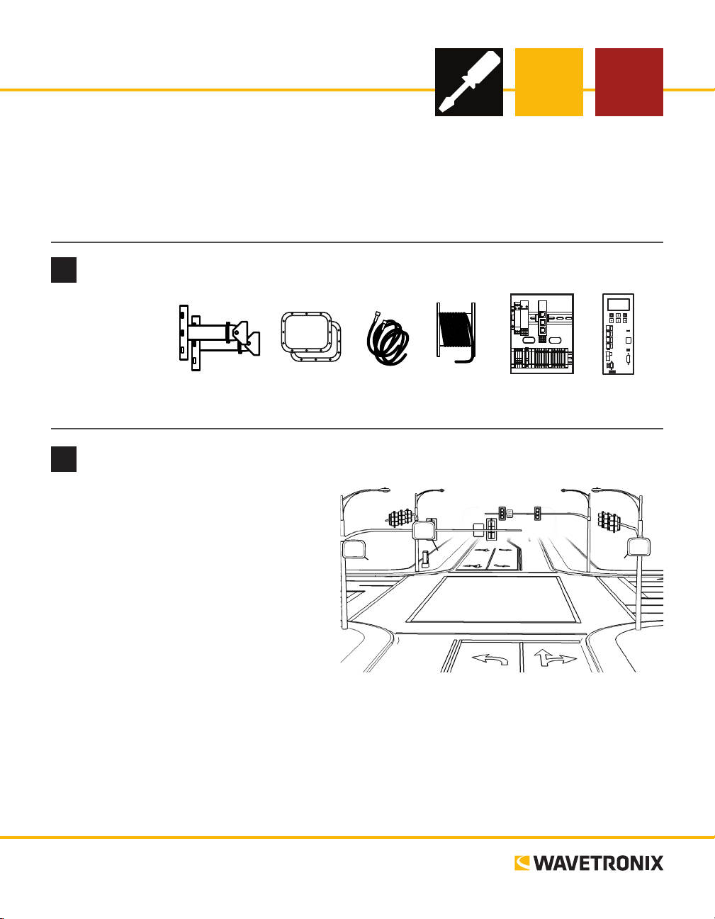
Ensure that all necessary components are available
1
ese components,
all available from
Wavetronix, may
be needed to install
your SmartSensor
Matrix.
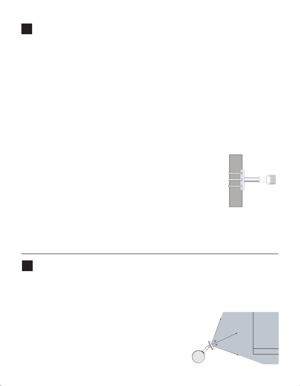
Select the sensor’s location
2
Mount
Brackets
Sensors
Accessory
Cables
6-conductor
Cable
Preassembled
Backplate
Click 650
e following are the suggested Matrix mounting locations:
1 The back side of mast arm – Allows the
sensor to be placed near the lanes of interest
and may be the best location option for
wide approaches. Mount the sensor toward
the end of the arm, to avoid occlusion from
passing vehicles, but make there’s at least
6 . (1.8 m) lateral seperation between the
sensor and the rst lane of interest.
2 The far side of approach – Usually mount-
ed on a corner vertical mast pole or strain
pole. If the sensor is mounted on a vertical pole with a mast arm, you can usually avoid occlusion by
mounting the sensor away from or below the mast arm.
3 The near side of approach – Typically best if detecting the le turn lane is less important; also allows
you to mount the sensor high enough to avoid occlusion.
Note. e sensor must be at least 6 . (1.8 m) from the rst lane of interest—that is, if you drew a line from
the sensor to the ground, that line should hit the ground at least 6 . from the rst lane you need to detect.
www.wavetronix.com
801.734.7200
➋
➊
➌
Page 2
Determine the height and mount the sensor
45°
45°
3
Use the following guidelines to determine the best mounting height:
˽ e sensor should be placed at a height of roughly 20 ., give or take 5 . (6.1 ± 1.5 m).
˽ e maximum recommended mounting height is 60 . (18.2 m). e minimum recommended mount-
ing height is 12 . (3.6 m). (e farther you install the sensor from the rst lane of interest, the higher
the sensor should be mounted.)
˽ Take into consideration the sensor’s footprint, which reaches 140 . (42.7 m) from the sensor. Place the
sensor so that the footprint covers all the areas of interest. Be aware that in certain conditions, lanes that
have stop bars or detection zones placed at extended range may show some loss in performance, even
with a proper mounting height.
˽ e mast arm is frequently a good place to mount the sensor.
˽ e mounting position should have a clear view of the detection area. Poles, mast arms, signal heads or
other objects should not block the view of the detection area.
˽ Placing the sensor higher will result in less occlusion. Placing it lower could result in more occlusion.
However, if the nearest detection area is less than about 20 . (6.1 m) away, the sensor may perform bet-
ter with a lower mounting position.
To attach the mount bracket to the pole:
1 Insert the stainless steel straps through the slots in the mount bracket.
2 Position the mount on the pole so the mount head points toward the lanes of
interest at a 45° angle.
3 Tighten the strap screws.
To securely fasten the sensor to the mount bracket:
1 Align the bolts on the sensor’s backplate with the holes in the mount bracket. e eight-pin connector
receptacle on the bottom of the sensor should be pointing towards the ground.
2 Place the lock washers onto the bolts aer the bolts are in the mount bracket holes.
3 read on the nuts and tighten.
Align sensor to roadway
4
e sensor’s eld of view fans out 45° to both sides. You will usually want to position the radar beam so that
its 90° footprint covers all lanes approaching the stop bar.
Also, the eld of view’s front edge must be aligned to provide some coverage beyond the stop bar so you can
detect vehicles that don’t stop at or behind the stop line, as well as vehicles exiting queues.
1 Adjust the side-to-side angle so the front edge of the eld of view
provides a view downstream of the stop bar.
2 Tilt the sensor down to aim it at the center of the lanes of interest.
3 If necessary, rotate the sensor so that the bottom edge of the
sensor is parallel with the roadway. is is necessary where the
intersection approach has a signicant grade.
Pan sensor towards
stop bar
Stop Bar
Edge of First Lane of Interest
Page 3
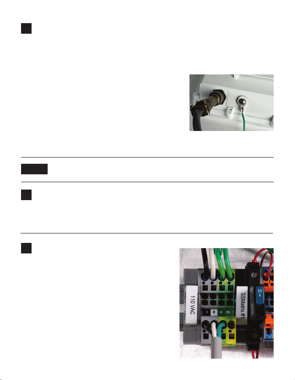
Attach the 6-conductor cable and ground the sensor
5
1 Tear the tab o the silicon dielectric compound and squeeze about 25% of it into the connector at the
base of the sensor. Wipe o any excess compound.
2 Insert the cable into the connector and twist clockwise until you hear it click into place.
3 To avoid undue movement from wind, strap the cable to the pole or run it through a conduit, but leave
a small amount of slack at the top of the cable to reduce strain.
e SmartSensor Matrix provides its own surge protection, so there is
no need for a pole-mount box on the sensor side of the cable. Instead,
the cable should run straight to the main trac cabinet; landing the
cable in the cabinet will be covered later in this document.
It is necessary, however, to ground the sensor:
1 Connect a grounding wire to the grounding lug on the bottom of
the sensor.
2 Connect the other end of the grounding wire to the earth ground for the pole that the sensor is
mounted on. Do not attempt to run the grounding wire back to the main trac cabinet.
Note
6
e SmartSensor Matrix preassembled backplate must be installed in the main trac cabinet. To do so,
locate the area planned for mounting the backplate; it can usually be mounted on the side panel of a NEMAstyle cabinet. en attach the backplate with the U-channel mounting screws.
7
Use the following steps to connect power to the AC terminal
block on the bottom DIN rail:
1 Connect a line wire (usually a black wire) to the bottom of
the “L” terminal block.
2 Connect a neutral wire (usually a white wire) to the bottom
side of the “N” terminal block.
3 Connect a ground wire (usually a green wire) to the bottom
of the “G” terminal block.
4 Turn on AC mains power.
5 Press the circuit breaker switch on the le side of the top
DIN rail to switch power to the backplate.
6 Verify power is regulated by seeing that the DC OK LEDs
are illuminated on the Click 201/202/204.
If you’re using a Click 650 with your Matrix, consult the 650 quick reference guide for the rest
of your installation. If you’re using a preassembled backplate, complete the steps below.
Mount the preassembled backplate in the main trac cabinet
Wire power to backplate
Page 4
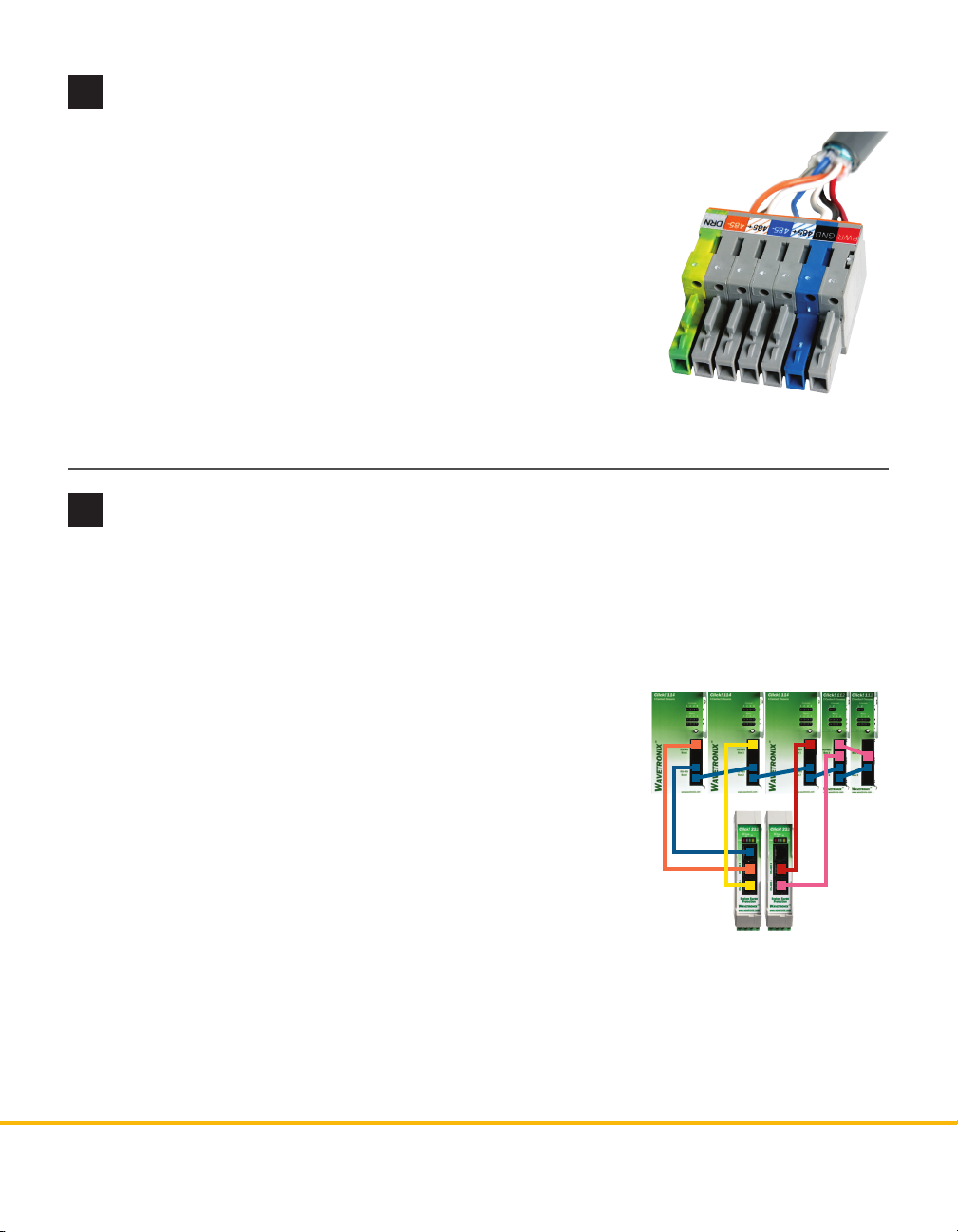
Terminate the SmartSensor 6-conductor cable
8
To land the 6-conductor cable into the terminal block section:
1 Aer routing your SmartSensor 6-conductor cable into the cabinet, carefully strip
back the cable jacket and shielding on the service end of the cable.
2 Open the insulation displacement connectors on the plug by inserting a
small screwdriver into each square slot and rocking it back.
3 Insert the wire leads into the bottom side of the plug-in terminal accord-
ing to the colors of the wires and the labels on the plug. Make sure the
wires are completely inserted in the terminal.
4 Close the insulation displacement connector by reinserting the screw-
driver into the square slot and rocking it forward. e plug-in terminals
will automatically complete the electrical connection. ere is no need
to manually strip the insulation on the end of each wire.
5 If you removed the plug to wire it, insert it back into the terminal block section.
Connect to the detector rack cards
9
Finally, connect to detector rack cards. You can use the Click 104, which mounts on a DIN rail, but these
instructions refer specically to the Click 112/114 detector rack cards.
e Click 222 has three RJ-11 jacks on the faceplate; these jacks have the following functions:
˽ RS-485 A – Connects the data bus from sensor 1 to the detector rack cards.
˽ RS-485 B – Connects the data bus from sensor 2 to the detector rack cards.
˽ RS-485 Bridge – Connects the conguration buses from sensors 1 and
2 to the control bridge, to the detector rack cards, and to the T-bus.
is jack combines the input from ports C and D.
Note. For information about how to congure the Click 112/114, see the
Click 100-400 Series User Guide or the Click 112/114 Quick-Reference Guide.
To connect to the detector rack cards:
1 Make sure the DIP switches are set.
2 Connect from the Click 222 RS-485 A port to a bus 1 port on the ap-
propriate rack card. Connect from the Click 222 RS-485 B port to a bus
1 port on another rack card.
3 If you are using Click 112 cards, use a patch cord to share bus 1 between cards dedicated to the same
sensor. If you have more than two sensors in your system, repeat steps 1–3 to connect bus 1 for all
remaining rack cards.
4 Connect from a Click 222 bridge port to bus 2 of the rack cards.
5 Daisy-chain between the bus 2 ports of all of the rack cards for device conguration.
© 2015 Wavetronix LLC. All rights reserved. Protected by US Pat. Nos. 6,556,916; 6,693,557; 7,426,450; 7,427,930; 7,573,400; 7,889,097; 7,889,098; 7,924,170; 7,991,542; 8,248,272; 8,665,113;
and Cdn. Pat. Nos. 2,461,411; 2,434,756; 2,512,689; and Euro. Pat. Nos. 1435036; 1438702; 1611458. Other US and international patents pending. Wavetronix, SmartSensor, Click, Command and all associated logos are trademarks of Wavetronix LLC. All other product or brand names as they appear are trademarks or registered trademarks of their respective holders.
Product specifications are subject to change without notice. This material is provided for informational purposes only; Wavetronix assumes no liability related to its use.
WX-500-0172
 Loading...